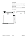
1
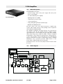
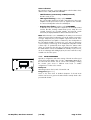
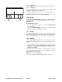
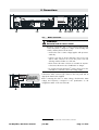
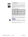
D6 Amplifier
Hardware manual (1.9 EN)
Symbols on the equipment
Please refer to the information in the operating
manual.
WARNING!
Dangerous voltage!
General Information
D6 Amplifier
Hardware manual
Version 1.9 EN, 02/2014, D2017.EN.01
Copyright © 2014 by d&b audiotechnik GmbH; all rights reserved.
Keep this manual with the product or in a safe place so that it is
available for future reference.
When reselling this product, hand over this manual to the new
customer.
If you supply d&b products, please draw the attention of your
customers to this manual. Enclose the relevant manuals with the systems.
If you require additional manuals for this purpose, you can order them
from d&b.
d&b audiotechnik GmbH
Eugen-Adolff-Strasse 134, D-71522 Backnang, Germany
Telephone +49-7191-9669-0, Fax +49-7191-95 00 00
E-mail: [email protected], Internet: www.dbaudio.com
Contents
1. Introduction......................................................................4
1.1. Intended use...............................................................................................4
1.2. Scope of supply.........................................................................................4
1.3. Maintenance/Service...............................................................................5
2. D6 Amplifier.....................................................................6
2.1. D6 based systems.....................................................................................6
2.2. Block diagram............................................................................................6
2.3. Power supply..............................................................................................7
2.3.1. Inrush current limiter.....................................................................7
2.3.2. Mains voltage monitoring...........................................................7
2.4. Fan.................................................................................................................7
2.5. D6 power amplifiers.................................................................................7
2.6. Digital signal processing..........................................................................7
2.7. Remote control...........................................................................................7
3. Controls and indicators....................................................8
3.1. Controls........................................................................................................8
3.1.1. Power switch...................................................................................8
3.1.2. MUTE A/B switch...........................................................................8
3.1.3. LEVEL/PUSH MENU.....................................................................9
3.2. Indicators...................................................................................................10
3.2.1. LC Display.....................................................................................10
3.2.2. ISP LED...........................................................................................10
3.2.3. GR LED...........................................................................................10
3.2.4. OVL LED........................................................................................10
4. Connections....................................................................11
4.1. Mains connector......................................................................................11
4.2. Signal inputs and link outputs.............................................................12
4.2.1. INPUT A/B and LINK A/B.........................................................12
4.2.2. INPUT DIGITAL AES/EBU and LINK......................................12
4.3. Loudspeaker output connectors - OUT A/B...................................13
4.4. REMOTE interface..................................................................................14
4.5. SERVICE.....................................................................................................14
5. Installation and operation............................................15
5.1. Rack mounting and cooling..................................................................15
5.2. Operation.................................................................................................16
5.2.1. Power consumption and power loss......................................16
5.2.2. Mains supply................................................................................17
5.2.3. Operating conditions.................................................................17
6. Technical specifications..................................................18
6.1. Dimensions................................................................................................20
7. Manufacturer's declarations.........................................21
7.1. EU declaration of conformity (CE symbol).......................................21
7.2. WEEE Declaration (Disposal)...............................................................21
D6 Amplifier, Hardware manual
(1.9 EN)
Contents - 1
1. Introduction
This manual describes the facilities and basic functions of the hardware
of the D6 amplifier. A detailed description of the D6 software (firmware)
menu structure and access is given in the D6 Software manual, which is
also provided with the D6.
1.1.
Intended use
The D6 amplifier is a two channel power amplifier and controller unit. It
is designed for use with all current d&b loudspeakers except 2-Way
Active, V-Series and B2-SUB systems. A linear mode is available
allowing the D6 to be used as a linear power amplifier.
NOTICE: The device complies with the electromagnetic compatibility
requirements of EN 55103 (product family standard for audio, video,
audio-visual and entertainment lighting control apparatus for
professional use) for the environments E1 (residential), E2 (business and
commercial), E3 (outdoor use in urban areas) and E4 (outdoor use in
rural areas).
Acoustic interference and malfunctions may occur if the unit is operated
in the immediate vicinity of high-frequency transmitters (e.g. wireless
microphones, mobile phones, etc.). Damage to the unit is unlikely, but
cannot be excluded.
1.2.
Scope of supply
Before starting up please verify the shipment for completeness and
condition of the unit:
Quantity d&b Code
Fig. 1: D6 Amplifier, scope of supply
Description
1
Z2700
D6 Amplifier [1]
1
Z2610.xxx Power cord [2]
D6 CEE (specific to country)
1
K6007.050 RJ45 Patch cable [3]
0.5 m (1.6 ft) CAT 6/AWG 24-STP
(shielded twisted pair) to be used for
daisy chaining multiple amplifiers within a
rack.
1
Z6116
RJ 45 M Terminator [4]
1
D2017.EN
D6 Amplifier, Hardware manual [5]
1
D2018.EN
D6 Amplifier, Software manual [6]
Tab. 1: D6 Amplifier, scope of supply
If there is any sign of obvious damage to the unit and/or the power
cord do not operate the unit. Please contact your local dealer from
whom you received the unit.
D6 Amplifier, Hardware manual
(1.9 EN)
Page 4 of 24
1.3.
Maintenance/Service
Do not open the unit. No user serviceable parts inside. In case of any
damage do not operate the unit under any circumstances.
Refer servicing only to qualified service personnel authorized by
d&b audiotechnik. In particular if:
- objects or liquids have entered the unit.
- the unit is not operating normally.
- the unit was dropped or the housing is damaged.
CAUTION!
Potential risk of explosion.
The unit incorporates a lithium battery which may cause danger
of explosion if not replaced correctly.
- Refer replacement only to qualified service personnel
authorized by d&b audiotechnik.
- Only replace with the same type of battery.
D6 Amplifier, Hardware manual
(1.9 EN)
Page 5 of 24
2. D6 Amplifier
2.1.
D6 based systems
The D6 Amplifier incorporates:
- universal voltage, switch mode power supply with active power
factor correction (PFC)
- two channel Class D power amplifier
Fig. 2: D6 Amplifier
- digital signal processors (DSP)
- comprehensive protection circuits
- controls and indicators
- analog and digital signal inputs and link outputs
- REMOTE and SERVICE interface
The level control on the front panel incorporates a digital rotary
encoder, which enables selection of all operating modes in conjunction
with a Liquid Crystal Display (LCD).
User definable equalization and delay functions are incorporated in
each channel of the D6. The 4-band parametric equalizer provides
optional Boost/Cut or Notch filtering and the signal delay capability
allows delay settings of up to 340 ms (= 100 m / 328 ft) to be applied
independently to either channel. A signal generator offering pink noise
or sine wave program is also incorporated for test and alignment
purposes. Each unit can be given a unique Device Name to simplify
identification and a password protected LOCK function is also
incorporated to inhibit unauthorized set up changes.
The D6 is housed in a 19" x 351 mm (13.8") 2 rack unit enclosure made
from steel.
2.2.
Block diagram
LC Display
Input
Ch A
Ch B
Link A>B
analog
> LINEAR
> LINEAR
off
Channel A
D6
remote
interface
uC
Channel B
Input
monitoring
Input
routing
Analog A
Analog B
Digital A
Digital B
pilot signals
for load
monitoring
sine wave or
pink noise for
acoustic tests
Signal
generator
Delay
t
User
EQ
System
EQ/XO
Coil temp.
t°
1-/2-
Power
amplifier
1+/2+
Dynamics
1-/2I
Excursion
D6 Amplifier, Hardware manual
1+/2+
Power supply
(1.9 EN)
Information
on headroom,
temperature,
power, mains
voltage
Z analysis
for load
monitoring
Page 6 of 24
2.3.
Power supply
The switch mode mains power supply permits worldwide application
without the need for mains voltage switching or conversion. The power
supply incorporates active Power Factor Correction (PFC) which
provides a clean and highly efficient sinusoidal current draw, thus
providing highest performance under adverse mains conditions or when
very long power cabling is necessary.
2.3.1. Inrush current limiter
A mains inrush current limiter provides a "soft start" and enables
several units to be powered up at the same time without overloading
the mains power supply.
2.3.2. Mains voltage monitoring
The mains voltage and frequency are recorded by the power supply
and can be viewed on the LCD display. Where voltages outside of this
range are present, a self-resetting protective circuit responds quickly to
isolate the internal amplifier power supply leaving only a supervisory
circuit to monitor the mains voltage. The D6 accepts mains voltages of
up to 400 VAC without damage to the unit.
2.4.
Fan
A level and temperature controlled fan is incorporated for cooling the
internal components, which allows greater cooling during louder
program material. The fan speed is consequently reduced during quieter
passages preventing background noise interference. If the D6 heats up
a "Temp. Warning" is given out and the fan will give full cooling power
permanently.
2.5.
D6 power amplifiers
The two power amplifiers fitted to the D6 are utilizing Class D
technology similar to a switch mode power supply. Compared to the
known linear amplifier concept (Class A, AB, G or H) the Class D power
amplifiers produce less heat and allow for a compact and light weight
design.
The rated sine wave output power of each channel is 2 x 600 W into an
4 ohms load, decreasing to 2 x 350 W into a 8 ohms load.
2.6.
Digital signal processing
The digital signal processing provides loudspeaker specific setups that
are selected using the front panel controls. These setups include all
loudspeaker specific equalization and protection functions. The basic
latency of the D6 is 0.3 ms (analog input including AD/DA conversion).
2.7.
Remote control
The REMOTE interface (2 x RJ 45) can be used with the d&b Remote
network (CAN-Bus) to integrate the D6 into a control and monitoring
system.
D6 Amplifier, Hardware manual
(1.9 EN)
Page 7 of 24
3. Controls and indicators
3.1.
Controls
3.1.1. Power switch
The power switch [1] is a rocker switch type. It does not isolate the unit
from the mains power.
- OFF
The unit is switched off. The power consumption is low (1 W typical).
- ON
The unit is switched on and ready for operation.
3.1.2. MUTE A/B switch
When the mains power switch is set to the on position, the MUTE A/B
switches (push buttons) [2] can be used to mute the respective amplifier
channel or place the D6 in Standby mode.
Note: The setting of the MUTE A/B switch is stored in the D6 when the
mains power is turned off or disconnected. After switching on or
reconnecting the unit it will revert to its previous status.
MUTE / STANDBY
- A brief press of the MUTE A or B switch will mute the corresponding
channel A or B. The channel is unmuted by briefly pressing the
corresponding MUTE switch.
- A longer press (approx. 1.5 s) of MUTE A or B places the D6 in
Standby mode. Briefly pressing the MUTE A or B switch again powers
on the D6 ready for use. The D6 may also be powered back on by
remote control from Standby mode.
D6 Amplifier, Hardware manual
(1.9 EN)
Page 8 of 24
Status indication
The switch incorporates a green LED indicator which indicates three
different states – ON, MUTE and STANDBY.
- LED illuminates permanently ⇒ ON (unmuted)
The D6 is ready for use.
- LED regular flashing (1:1 duty cycle): ⇒ MUTE
The corresponding channel of the D6 is muted however the power
amplifiers remain powered but receive no signal from the controller.
A connected loudspeaker is therefore still damped.
- Regular short flashes (1:8 duty cycle): ⇒ STANDBY
In Standby mode the loudspeaker outputs are electronically isolated
and the D6 idles, drawing minimal mains power. Only the most
essential functions are provided. Display and network remain
functional, the display illumination will be switched off after 10 s.
Note: When the D6 is set to STANDBY (or the mains power is turned
off) the movement of the loudspeaker cones in the cabinets connected is
no longer damped by the power amplifier output. This removal of the
damping makes them susceptible to excitation by other loudspeakers in
the surroundings. Audible resonances may occur, and even absorption
of low frequency sound energy as the undamped loudspeakers act like
a "bass trap". To permanently mute single subwoofer cabinets when
others are operated at the same time it is therefore preferable to use
the MUTE function instead of STANDBY. The Standby mode, however,
can be of advantage with mid/high systems, because it will remove any
residual noise from the system.
3.1.3. LEVEL/PUSH MENU
Operation, configuration and status viewing of the D6 are all accessed
via the front panel digital rotary encoder - LEVEL/PUSH MENU [3]. In
the main menu the encoder acts as a level control. Pushing or turning
the encoder gives access to different menu levels or enables
configurations or values to be entered.
Brief press
Alternating between level control of channel A or B.
Long press (approx. 1 s)
Access to the menu level. A detailed description of the D6 menu
structure and access is given in the D6 Software manual, which is also
provided with the D6.
D6 Amplifier, Hardware manual
(1.9 EN)
Page 9 of 24
3.2.
Indicators
3.2.1. LC Display
The LC Display [4] serves as a user interface and display for all
configuration settings and status information.
The display is illuminated and can be set to "on/off/timeout 10 s."
A detailed description of the menu structure and access is given in the
D6 Software manual, which is also provided with the D6.
3.2.2. ISP LED
The ISP LED [5] (Input Signal Present) indication is unaffected by the
setting of the level control and the MUTE function but will not operate in
STANDBY mode.
The ISP LED illuminates green:
- when the analog input signal fed to the D6 analog inputs
exceeds –30 dBu.
- when the D6 digital input is locked to 48 or 96 kHz and the
digital signal exceeds –57 dBFS (FS = Full Scale).
3.2.3. GR LED
The GR LED [6] (Gain Reduction) illuminates yellow depending on the
input signal. The D6 limiter circuit reduces gain by more than 3 dB. This
state is not critical but indicates that the system has reached its limits.
3.2.4. OVL LED
The OVL LED [7] (Overload) illuminates red depending on the input
signal. Either the input signal level is too high or gain reduction exceeds
12 dB.
- If in doubt please reduce the input gain at the D6 level control. If
caused by the gain reduction, the OVL LED stops illuminating. If the
condition does not change, the input signal to the D6 is too high
(greater than +25 dBu).
An overload could also be caused by accumulating the source input
A+B or by high gain settings (boosts) in the single EQ bands, while the
input signal is lower than +25 dBu.
Flashes (1:1 mark space) ⇒ Error
An error message will be displayed altering with the device name.
D6 Amplifier, Hardware manual
(1.9 EN)
Page 10 of 24
4. Connections
D6
CH A
MAINS SUPPLY
VOLTAGE SEE LABEL
~ 50/60 Hz, 1000 W
DIGITAL AES/EBU
OUT
OUT
A
REMOTE
B
4.1.
SERVICE
ANALOG
CH B
Mains connector
WARNING!
Potential risk of electric shock.
The D6 is a protective class 1 unit. A missing earth (ground)
contact may lead to dangerous voltages in the housing and
controls, and may lead to electric shock.
- Connect the unit to mains voltage supplies with protective
earth only.
- If there is any sign of obvious damage to the power cord
and/or mains connector do not use the power cord and
exchange it before further use of the unit.
- Please ensure the mains connector is accessible at any time
to disconnect the unit in case of malfunction or danger.
- Do not disconnect the PowerCon®1 mains connector from the
unit while it is connected to the mains voltage supply.
A PowerCon mains connector [8] is fitted on the rear panel and an
appropriate mains lead is supplied.
D6
D6
100-127V / 220-240V
ÉZ2700.000WË
Z270000000001
D6
WEEE
0615
Before connecting the device to mains voltage, check that the mains
voltage and frequency correspond to the specifications on the
configuration sticker on the rear of the D6.
CH A
MAINS SUPPLY
VOLTAGE SEE LABEL
DIGITAL AES/EBU
~ 50/60 Hz, 1000 W
OUT
A
OUT
B
REMOTE
SERVICE
ANALOG
CH B
1
D6 Amplifier, Hardware manual
PowerCon® is a registered trademark of the Neutrik AG, Liechtenstein
(1.9 EN)
Page 11 of 24
4.2.
Signal inputs and link outputs
NOTICE: To meet the EMC requirements only use shielded cabling and
properly fitted connectors.
4.2.1. INPUT A/B and LINK A/B
A 3 pin female XLR input connector [9] is provided for channel A and B.
The inputs are electronically balanced.
Wired in parallel is a 3 pin male XLR input link connector [10] used to
feed the input signal on to the next device in the system signal chain.
Fig. 3: Pin assignment ANALOG INPUT/LINK
4.2.2. INPUT DIGITAL AES/EBU and LINK
A 3 pin female XLR AES/EBU [11] (AES 3) input and a 3 pin male XLR
LINK output [12] are provided.
The balanced input utilizes a transformer and is electrically isolated.
Fig. 4: Pin assignment DIGITAL INPUT/LINK
Buffer
Digital LINK
Power fail (Bypass)
Digital INPUT
(AES/EBU)
Fig. 5: Digital INPUT Bypass
D6 Amplifier, Hardware manual
The digital LINK output may be used to feed a refreshed input signal to
the next device in the system signal chain. The signal shape (the rising
and trailing edges of the signal) and level are refreshed with an analog
signal amplifier.
A power fail relay is incorporated to prevent interruption of the signal
chain should there be a power failure. In this situation, the digital input
signal bypasses the analog buffer amplifier and is routed directly to the
LINK output.
(1.9 EN)
Page 12 of 24
4.3.
Loudspeaker output connectors - OUT A/B
WARNING!
Potential risk of electric shock.
The amplifier's output pins can carry dangerous voltages.
- Only use isolated loudspeaker cables with correctly fitted
connectors.
- Never connect an amplifier output pin to any other input or
output connector pin or protective earth (ground).
INPUT A
INPUT B
AMP A
AMP B
OUT A
OUT B
The D6 amplifier is supplied with NL4 output connectors [13]. Pins
1+/2+ and 1—/2— are wired in parallel and carry signal.
Pin equivalents of the amplifier's output connectors and the type of
loudspeaker cabinets are listed in the table below.
Fig. 6: NL4 Loudspeaker output
connectors and channel assignment
D6 Output
NL4
Speaker type
NL4
+
1+/2+
TOP +
1+
—
1—/2—
TOP —
1—
SUB +
2+
SUB —
2—
Tab. 2: D6 pin assignment
Tab. 3: Pin assignment
loudspeaker
D6 Amplifier, Hardware manual
(1.9 EN)
Page 13 of 24
4.4.
REMOTE interface
The D6 is fitted with a 2-wire serial remote control interface, (2 x RJ 45
[14]) carrying CAN-Bus signals.
All pins of both connectors are wired in parallel allowing either to be
used as the input or output. Where remote control networking conforms
to a "Bus or Ring topology" one connector is used for the incoming
signal and the second connector allows for direct connection to another
device (daisy chaining) or for terminating the last device at the end of a
CAN-Bus segment.
The reference ground of the CAN-Bus is hard wired to common ground
(protective earth) of the device.
Pin
1
2
3
4
5
6
7
8
Signal
CAN_H
CAN_L
-
Enclosure
GND
Remark
"CAN high bus" signal (active high)
"CAN low bus" signal (active low)
CAN Ground
The "CAN Ground" is routed via the cable shielding. Within the CANBus network, shielded cables and shielded RJ 45 connectors must be
used while the cable shielding must be connected to both sides of the
RJ 45 connector.
A detailed description of remote control via the d&b Remote network
(CAN-Bus) is given in the technical information TI 312 (d&b code
D5312.E.) which can be downloaded from the d&b website at
www.dbaudio.com.
4.5.
SERVICE
The SERVICE interface [15] (USB type B connector) allows operating
software and loudspeaker configuration updates to be loaded into the
unit.
A detailed description of the update procedure is given in the D6
Software manual, which is also provided with the D6.
D6 Amplifier, Hardware manual
(1.9 EN)
Page 14 of 24
5. Installation and operation
NOTICE: Observe the operating conditions and limits as given in the
technical specifications. Please ensure that ...
- no moisture or liquids can enter the unit,
e.g. rain, excessive humidity or steam, oil steam or splashes or
knocked over liquids (e.g. Drinks).
- the unit is not exposed to additional heat,
e.g. excessive heat from additional equipment or direct sunlight
- no dust or other small particles can enter the unit. In combination
with moisture this could lead to malfunction of the unit.
5.1.
Rack mounting and cooling
Rack mounting
D6 amplifier enclosures are designed to fit into a standard 19"
equipment rack or cabinet.
When specifying a rack, be sure to allow extra depth (100 mm / 4" is
usually sufficient) to accommodate the cables and connectors at the rear
of the amplifier.
When mounting amplifiers into a 19" rack cabinet, do not just rely on
fixing and supporting amplifiers by their front panels. Provide additional
support ...
- using shelves fixed to the inner sides of the cabinet or rack
- or the mounting holes provided on the amplifier rear mounted rack
ears. This is particularly important if amplifiers are being racked up
for touring use.
Cooling
Thermal conditions are a vital factor ensuring operational safety of the
power amplifier. The D6 amplifier has an internal fan that draws cool
air into the housing from the rear. It expels heated air through the vents
on the front panel.
- Please ensure that adequate cool airflow is provided to avoid a
build-up of hot air inside the rack leading to overheating. Do not
block or cover the rear panel air intake or the vents on the front
panel of the amplifier.
- If amplifiers are installed in sealed cabinets (e.g. in fixed installations)
use additional fan modules with filters that can be easily replaced
without opening the sealed cabinets.
D6 Amplifier, Hardware manual
(1.9 EN)
Page 15 of 24
5.2.
Operation
5.2.1. Power consumption and power loss
The power required from the mains supply and the waste heat
produced by the amplifiers power loss vary depending on the load
impedance and the signal levels and characteristics (e.g. speech, music).
In practice, the theoretical peak power consumption of a system will
only be sustained for a short period of time. Basing mains current and
air conditioning plant requirements on the peak power consumption of
the sound system would result in a generously over-specified
installation. The key factor in power consumption calculations is the crest
factor (CF) of the music or speech signal - the ratio of peak to
sustainable RMS voltage of the signal.
A crest factor of 2.4 represents 1/3 of the maximum sine output power
and it can be seen as the worst case signal that can be accessed in real
world conditions. A proper power distribution should be able to handle
the current ratings given in the table below referring to CF 2.4. Using
the D6 temporarily with well known signals of higher crest factor, the
power distribution can be downsized within the range given in the table.
The table gives power figures for various types of signal waveforms.
They were measured on a D6 driving a 4 ohm load (both channels) to
the clipping point of both channels using a sine wave burst signal of
24 dBu with a variable duty cycle. The mains power supply used for the
measurements supplied an ideal sine wave with 230 V/50 – 60 Hz at
an internal resistance of 0.5 ohms (0.12/0.1 ohms for 115/100 V)
equivalent to a mains lead of 20 m (65.6 ft) with a cross section of
1.5 mm2 (6 mm2 / 8 mm2 for 115/100 V).
Signal
waveform
CF
Duty
Pout [W]
Pin [W]
Ploss [W]
Iin [A]
Uin [V]
BTU/hr
kCal/hr
Sinus
1.4
1/1
1200
1560
360
6.8
230
1228
310
1645
445
14.3
115
1518
383
1715
515
17.2
100
1757
443
520
120
2.3
230
410
103
550
150
4.8
115
512
129
570
170
5.7
100
580
146
Highly compressed
music*
Music with low
dynamic range
2.4
4.0
1/3
1/8
400
150
215
65
1.0
230
222
56
220
70
2.0
115
239
60
220
70
2.2
100
239
60
Tab. 4: D6 Power balance
Key:
CF: Crest factor, Duty: Duty cycle, Pout[W]: Max. average output power (sum of both channels), Pin[W]: Input power (effective power)
Ploss: Power loss (thermal power), Iin[A]: Resulting current, Uin [V]: Mains voltage
* Maximum practicable operation
D6 Amplifier, Hardware manual
(1.9 EN)
Page 16 of 24
5.2.2. Mains supply
The table below indicates the number of devices per phase conductor
when full output power is required.
Mains supply
Number of devices
230 V / 16 A
Max. 4
115/100 V / 15 A
Max. 2
In the USA and Japan we recommend the use of mains leads with a
high cross section (min. 4 mm2 / AWG 12).
5.2.3. Operating conditions
The following diagram shows the thermal operating range within which
the technical data will be maintained. The operation beyond this range
is possible for a short time and for thermal reasons this will trigger the
amplifier protection circuit into thermal overload.
Fig. 7: Average maximum total output power vs. ambient temperature
As explained in section 5.2.1, a worst case signal with a CF of 2.4 is
producing 1/3 of the rated sine output power or 200 watts at 4 ohms
per channel (400 watts total).
- The thermal management of the D6 is designed to deliver this power
for an unlimited amount of time within an ambient temperature of
up to 40° C (104° F).
- With higher ambient temperatures, the maximum average
output power that can be delivered without entering thermal
protection, is reducing linearly as shown in the diagram above.
- When using the D6 at its upper temperature limit of 45° C
(113° F), the maximum continuous output power is 340 watts total
or 170 watts per channel.
Again referring to section 5.2.1 - Tab. 4 - "D6 Power balance" - the unit
will work properly with e.g. 150 watts total when either
- running 4 ohms loads when the signal has a CF of 4.0
- or running 8 ohms loads if the worst case signal with a CF of 2.4
needs to be handled.
The maximum possible output power of 2 x 600 W at 4 ohms, which for
thermal reasons could only be supplied in short term (within minutes), is
unaffected by the ambient temperature.
D6 Amplifier, Hardware manual
(1.9 EN)
Page 17 of 24
6. Technical specifications
Displays
ISP A/B..................................................................Input Signal Present indicator (green)
GR A/B.........................................................................Gain Reduction indicator (yellow)
OVL A/B...........................................................................Overload/Error indicator (red)
MUTE A/B......................................................................Mute/Standby indicator (green)
Liquid Crystal Display (LCD).....................................Graphic display / 120 x 32 Pixel
Controls
POWER..............................................................................................................Power switch
MUTE A/B........................................................................................Mute /Standby switch
LEVEL/PUSH MENU......................................................................Digital rotary encoder
access to all functions (Channel A /B) including:
Level control..................................–57.5 dB to +6 dB with 0.5 dB detents
Input matrix.........................................................................................A, B, A+B
Functions.......................Loudspeaker specific circuits CUT/HFA/HFC/CPL
4-band equalizer...........................................................Optional PEQ/Notch
Delay setting.........................................0.3 to 340 ms with 0.1 ms detents
Configurations......................Current d&b loudspeakers and linear mode
....................................except 2-Way Active, V-Series and B2-SUB setups
Channel coupling.....................common access to Delay, EQ, Delay+EQ
Protection..............................Operator input inhibit /password protection
Remote control.....................................................................................CAN-Bus
Device name................................................................15 alphanumeric digits
Display illumination......................................................Off/On/Timeout 10 s
Frequency generator..............Pink noise or Sine wave, 10 Hz to 20 kHz
...........with 1 Hz detents, Level: –57.5 dB to +6 dB with 0.5 dB detents
Buzzer.......................................................Audible signal for error messages
Monitoring according to IEC 60849
‘Sound Systems for Emergency Purposes’
Input monitoring................................................................Detecting external Pilot signal
Load monitoring.......................................................Continuous impedance monitoring
..............................................................................using Pilot signal at 10 Hz and 20 kHz
System check..............................................................Manual impedance measurement
...........................................................................to calibrate before, and verify after use
Connectors
INPUT ANALOG CH A / CH B...........................................................XLR 3-pol. female
.........................................Pin assignment: 1 = GND, 2 = pos. signal, 3 = neg. signal
Input impedance.......................................................44 kohms, electronically balanced
Input CMRR, 100 Hz...........................................................................................< – 70 dB
Input CMRR, 10 kHz............................................................................................< – 50 dB
Maximum input level..............................................................................................+25 dBu
LINK ANALOG CH A / CH B................................................................XLR 3-pol. Male
.........................................Pin assignment: 1 = GND, 2 = pos. signal, 3 = neg. signal
.......................................................................................................................parallel to input
INPUT DIGITAL AES/EBU.......................................................XLR 3-pol. female, AES 3
.........................................................Pin assignment: 1 = GND, 2 = Signal, 3 = Signal
Input impedance.........................................................110 ohms, transformer balanced
Synchronization.................................Word-Sync: PLL-locked to source (slave mode)
LINK DIGITAL (Output).............................................................................XLR 3-pol. male
..........................................................................................................electronically balanced
..........................................................................................................analog signal buffering
.......................................................................................................power fail relay (Bypass)
.........................................................Pin assignment: 1 = GND, 2 = Signal, 3 = Signal
D6 Amplifier, Hardware manual
(1.9 EN)
Page 18 of 24
OUT A/B...........................................................................................................................NL4
.....................................................................................Pin assignment: 1+/2+: Output +
.....................................................................................................................1–/2–: Output –
REMOTE...................................................................................................2 x RJ 45 parallel
SERVICE.................................................................................................................USB Typ B
Protection circuits
Mains inrush current limiter............................................................1.5 A RMS at 230 V
........................................................................................................3 A RMS at 115/100 V
Speaker switch on delay..................................................................................Approx. 2 s
Self-resetting overvoltage protection...................................................Up to 400 VAC
Self-resetting overtemperature protection...........................................75 °C / 167 °F
Output short circuit protection......................................................................±40 A peak
Output DC protection.....................................................................................max. ±10 V
Audio data (linear setting with subsonic filter)
Rated output power (THD+N 0.1 %)................................................................................
........................................................2 x 350 W into 8 ohms, both channels are driven
........................................................2 x 600 W into 4 ohms, both channels are driven
Frequency response (–3 dB)...............................................
28 Hz to 24 kHz
THD+N (20 Hz – 20 kHz).....................................................................................< 0.1 %
IM (SMPTE)................................................................................................................< 0.1 %
S / N ratio (unweighted, RMS, analog input)................................................>105 dBr
S / N ratio (unweighted, RMS, digital input)..................................................>110 dBr
Damping factor (20 Hz – 1 kHz / 4 ohms)..............................................................>90
Crosstalk (20 Hz – 20 kHz)..............................................................................< – 65 dBr
Digital Signal Processing
Sampling rate..........................................................96 kHz / 27 Bit ADC / 24 Bit DAC
Basic delay analog input incl. conversion (AD/DA)............................................0.3 ms
Basic delay digital input.....................................0.22 ms (96 kHz) / 0.45 ms (48 kHz)
ADC Dynamic........................................................................................................> 110 dB
Input Dynamic........................................................................................................> 127 dB
DAC Dynamic........................................................................................................> 110 dB
Power consumption (typical values)
Standby.............................................................................................................................4 W
ON, without signal.......................................................................................................48 W
ON, Standard signal* at 4 Ohms (2 x 75 W)...................................................215 W
..........................................................*Standard signal: Pink noise, 1/8 nominal power
Power supply
Switch mode power supply...................................................................................................
.........................................................................with active power factor correction (PFC)
Mains connector....................................................................................PowerCon® (blue)
Operating range (min./nom./max.)................................85/115/130 V, 50 / 60 Hz
low range
..............................................................................................170/230/266 V, 50 / 60 Hz
high range
Mains fuse............................................................................2 x 8 A Time lag (T), internal
5 x 20 mm, high breaking capacity
D6 Amplifier, Hardware manual
(1.9 EN)
Page 19 of 24
Operating conditions
Temperature range*...................................................0° C to 40° C / 32° F to 104° F
.............................................*sum of average output power of 2 x 200 W (400 W)
................................................................................into 4 ohms for continuous operation
Temperature range**.................................................0° C to 45° C / 32° F to 113° F
..........................................................**reduced output power or short term operation
Humidity (rel.), average..........................................................................................< 80 %
Dimensions, weight
Height x width x depth................................................................ 2 RU x 19" x 351 mm
.................................................................................................................2 RU x 19" x 13.8"
Weight............................................................................................................8 kg / 17.6 lb
Dimensions
88 [3.46"]
6.1.
338 [13.31"]
483 [19.00"]
3 [0.12"]
324 [12.56"]
348 [13.70"]
443 [17.44"]
Fig. 8: Dimensions in mm [inch]
D6 Amplifier, Hardware manual
(1.9 EN)
Page 20 of 24
7. Manufacturer's declarations
7.1.
EU declaration of conformity (CE symbol)
This declaration applies to
- D6 Amplifier, Z2700
manufactured by d&b audiotechnik GmbH.
All products of type D6 starting from variant Z2700.000 are included,
provided they correspond to the original technical version and have not
been subject to any later design or electromechanical modifications.
We herewith declare that said products are in conformity with the
provisions of the respective EC directives including all applicable
amendments.
A detailed declaration is available on request and can be ordered from
d&b or downloaded from the d&b website at www.dbaudio.com.
7.2.
WEEE Declaration (Disposal)
Electrical and electronic equipment must be disposed of separately from
normal waste at the end of its operational lifetime.
Please dispose of this product according to the respective national
regulations or contractual agreements. If there are any further questions
concerning the disposal of this product please contact d&b audiotechnik.
D6 Amplifier, Hardware manual
(1.9 EN)
Page 21 of 24
D6 Amplifier, Hardware manual
(1.9 EN)
Page 22 of 24
D6 Amplifier, Hardware manual
(1.9 EN)
Page 23 of 24
D2017.EN.01, 02/2014 © d&b audiotechnik GmbH
d&b audiotechnik GmbH, Eugen-Adolff-Str. 134, D-71522 Backnang, Germany, Phone +49-7191-9669-0, Fax +49-7191-95 00 00_______