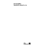
1
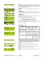
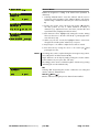
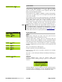
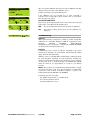
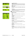
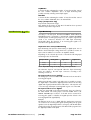
D6 Amplifier
Software manual (1.2 EN)
(Firmware V1.x.x)
General Information
D6 Amplifier
Software manual (Firmware V1.x.x)
Version 1.2 EN, 10/2011, D2018.EN .01
Copyright © 2011 by d&b audiotechnik GmbH; all rights reserved.
Keep this manual with the product or in a safe place so that it is
available for future reference.
When reselling this product, hand over this manual to the new
customer.
If you supply d&b products, please draw the attention of your
customers to this manual. Enclose the relevant manuals with the systems.
If you require additional manuals for this purpose, you can order them
from d&b.
d&b audiotechnik GmbH
Eugen-Adolff-Strasse 134, D-71522 Backnang, Germany
Telephone +49-7191-9669-0, Fax +49-7191-95 00 00
E-mail: [email protected], Internet: www.dbaudio.com
Contents
1. Introduction......................................................................4
1.1 Block diagram of the DSP software......................................................4
2. The D6 operating software.............................................5
2.1 Menu tree.....................................................................................................5
2.2 User interface..............................................................................................6
2.2.1 Conventions for the cursor and menu control........................6
2.3 Boot screen..................................................................................................7
2.4 Main screen.................................................................................................7
2.5 Settings menu..............................................................................................8
Input.....................................................................................................8
Channel A (B)....................................................................................8
Setup Channel A (B).....................................................................9
Source (Input routing)...........................................................9
Speaker.....................................................................................9
Filter_1, Filter_2, Filter_3..................................................10
Equalizer................................................................................10
Delay.......................................................................................11
Levels.......................................................................................12
Channel Name.....................................................................13
System Check.......................................................................14
Load Monitoring..................................................................15
Frequency Generator.........................................................17
Link A»B............................................................................................18
AmpPreset.......................................................................................18
Remote.............................................................................................20
Lock...................................................................................................20
Options............................................................................................21
Device Name...............................................................................22
Display...........................................................................................22
Information...................................................................................23
Log...........................................................................................23
Channel A (B)........................................................................24
Input Monitoring.........................................................................25
Important notes on Input Monitoring.............................25
Input Monitoring menu.......................................................26
Power Supply...............................................................................27
Buzzer............................................................................................27
2.6 Display messages.....................................................................................28
2.6.1 Error messages..............................................................................28
2.6.2 System Check, Load and Input Monitoring...........................29
2.6.3 Error messages during operation.............................................29
2.6.4 Further messages..........................................................................30
2.7 System Reset.............................................................................................30
3. D6 Firmware update.....................................................31
3.1 Firmware Installer....................................................................................31
3.2 D6 Firmware update via D6-D12-dbUpdate..................................31
3.3 D12 Firmware update via CAN-Bus and R10................................31
D6 Software manual (Firmware V1.x.x)
(1.2 EN)
Contents - 1
1. Introduction
This manual describes the structure, access (user interface) and functions
of the firmware of the d&b D6 amplifier. A detailed description of the
D6 hardware and technical specifications is given in the D6 Hardware
manual, which is also provided with the D6.
A number of publications with supplementary information on our
products are available from the documentation section of our website at
www.dbaudio.com. You can either download these directly or use the
online order form to request a printed version. If the document you
want is not detailed on the form, please enter the title in the box after
entering your address information.
1.1
Block diagram of the DSP software
DSP
ADC A
Loudspeaker
System
equalization
Delay
off
Equalizer
function
(PEQ/Notch)
Limiters:
Peak
Displacement
Thermal
DAC A
+
Input routing
Sine-wave
generator
Pink-noise
generator
ADC B
DAC B
Digital
In
Digital
Link
D6 Software manual (Firmware V1.x.x)
(1.2 EN)
Page 4 of 32
2. The D6 operating software
2.1
Menu tree
The menu structure of Channel A is shown in detail. The same structure
applies to Channel B.
The settings for the configuration switches Filter_1/_2/_3 are
dependent on the loudspeaker configuration (please refer to section ⇒
Filter_1, Filter_2, Filter_3 on page 10).
Key:
: Further sub menu
: Direct access within
the resp. level of hierarchy
D6 Software manual (Firmware V1.x.x)
(1.2 EN)
Page 5 of 32
2.2
D6 Stage right
Q-SUB
CUT HFA
EQ
EQ
User interface
The LCD [4] acts as a user interface for all of the menus within the D6.
The cursor is controlled via the digital rotary encoder, LEVEL/PUSH
MENU [3]. In the main menu the encoder acts as a level control. Pushing
or turning the encoder gives access to different menu levels or allows
configurations or values to be entered.
Also refer to the D6 Hardware manual, section 3. Controls and
indicators.
2.2.1
Conventions for the cursor and menu control
Position cursor
Turning the encoder moves the cursor through the menu. Turning to the
right moves the cursor down in the menu tree or to the right. Turning to
the left moves the cursor up in the menu tree or to the left. Pushing the
encoder activates the Edit-Cursor, except for switching functions (e.g.
"on/off"). In these instances pushing the encoder leads directly to a
change in value or condition (toggle).
Edit cursor
The current value is displayed beside the cursor and is changed by
turning the encoder. Turning to the right increases the value, tuning to
the left decreases it. A change is immediately effective, except for the
functions "Speaker Selection", "Lock", "Remote", "Device Name" and
"Backlight" where a confirmation is required. Exit the edit mode by
pushing the encoder and return to the Position-Cursor.
Information cursor
The Information-Cursor indicates fields within the menu tree where the
displayed data cannot be changed.
Menu change
An arrow indicates another menu level. Selecting it with the PositionCursor and pushing the encoder enters the corresponding submenu.
Back
Short click: exits the selected menu by moving back one level.
Long press (approx 1 sec.): navigates back to the main menu.
Scroll bar
Where a menu tree is longer than can be displayed, a scroll bar is
shown on the right hand side of the display for orientation.
Other cursors or signs
Highlight
A highlighted field indicates that the data displayed can be changed in
edit mode (see also Edit-Cursor above).
Pointer
In the submenus "Lock/Code" and "Device-Name" the field for text
input is highlighted and additionally indicated by an arrow.
D6 Software manual (Firmware V1.x.x)
(1.2 EN)
Page 6 of 32
2.3
D6
Boot screen
The boot procedure takes approximately 4 seconds during which the
device name, the manufacturer's name (d&b audiotechnik) and the
firmware version are displayed.
d&b
audiotechnik
D6 V X.xx
The transition to the Main screen is carried out automatically.
Fig. 1: Boot screen
2.4
The main screen displays all important settings and status information in
one view.
D6 Stage right
Q7
Q-SUB
-3.0dB
+0.0dB
CUT HFA
EQ 0.1 CSA 100
Main screen
EQ
In the first line the device name is displayed. If no device name has been
entered, the firmware version is displayed.
Link A B
indication
Fig. 2: Main screen
Device Name
Speaker
Level
Filter_1
D6 Stage right
Q7
Q-SUB
-3.0dB
+0.0dB
CUT HFA C+1 EQ 0.1 CSA 100
D
Delay on
EQ
Filter_2
Filter_3
EQ Master on
Remote on
Starting from the second line the main menu of the D6 is split into
channel A and B and the following settings and information are
displayed:
- loudspeaker setups (Speaker type)
- input gain
- status of the delay and
- Link A»B.
The lowest line shows the status or value of the following settings for
both channels:
- Filter_1, Filter_2, Filter_3 (value)
- EQ
- In the center of this status line the dbCAN-Id (if remote mode dbCAN
is selected) or the remote mode (if not dbCAN) is displayed. Please
refer to the Remote menu section on page 20.
Using the encoder (LEVEL/PUSH MENU) the input gain can be adjusted
in steps of 0.5 dB (–57.5 dB to +6 dB). A brief press on the encoder
changes between level control of channel A and B.
If an error occurs (the red OVL/Err-LED flashes), an error message with
channel information will alternate with the device name in the top line of
the LCD.
In Standby Mode, the display alternates between the device name and
“Standby”.
A long press (1 s) on the encoder enters the Settings menu.
D6 Software manual (Firmware V1.x.x)
(1.2 EN)
Page 7 of 32
2.5
Settings
Back
Input
Ch A
Ch B
Remote
Lock
Options
Id0.01
analog
Q7
Q-SUB
off
off
Press 2s
Settings menu
The Settings menu contains general settings for the device and gives
further access to submenus.
In the first line the dbCAN-Id is displayed on the right hand side. A
detailed description of the dbCAN-Id is given in the Remote section on
page 20 in this manual.
Back
Exits the submenu.
Fig. 3: Settings menu
Input
Settings
Back
Input
Ch A A
Selecting "Input" and pushing the encoder allows the setting of the input
type. Turning the encoder one detent to the right and back toggles
between analog and digital input.
analog
Q7
analog:
The analog input section INPUT A/B and INPUT LINK A/B is active.
digital:
The digital AES/EBU INPUT and LINK is active.
Input
digital 48kHz
Input
digital 96kHz
Fig. 4: Supported sampling rates
Input
digital 44kHz?
Fig. 5: Non supported sampling rate
e.g. 44.1 kHz
Input
ISP
digital sync?
GR OVL
ISP
GR OVL
Notes on the digital AES/EBU input ⇒ Sampling rates:
The input accepts signals with sampling rates of 48 or 96 kHz. The
frequency is detected automatically and is displayed as shown opposite.
Signals with other common sampling rates (32/44.1/88.2 kHz) are
detected but cannot be used by the D6. They are indicated by a
question mark (?) as shown opposite.
The digital inputs are supervised for correct synchronization with the
input signal. Short term interruptions or loss of quality are indicated by
flashing ISP-LEDs together with the message "sync?" instead of the
detected sampling rate.
If no sampling rate is displayed there is either no input signal or signal
with unusable quality or an unknown (non standard) sampling rate.
Input
Input
Ch A
Ch B
digital
A
A B
analog
Q7
Q-SUB
Channel A (B)
For both Channel A and B the functions and submenus (menu structure)
are similar. Therefore "Channel B" is stated in brackets (B).
Selecting "Channel A (B)" and pushing the encoder enters the submenu
"Setup Channel A (B)".
D6 Software manual (Firmware V1.x.x)
(1.2 EN)
Page 8 of 32
Setup Channel
Back
Source
Input A
Speaker
Q7
Source
Ch A
Ch B
A
Source (Input routing)
Input A+B
A
A B
Setup Channel A (B)
Q7
Q-SUB
Within the submenus "Channel A" and "Channel B" the input source for
the respective channel can be selected.
Selecting "Source" and pushing the encoder allows the setting of the
following routings:
Input A
Input B
The respective channel is fed from input A.
The respective channel is fed from input B.
Input A+B
The respective channel is fed from input A+B.
(Input A+B are summed with a 6 dB attenuation)
The status of the selected input source is displayed in the Settings menu
as shown in the graphics opposite.
Notes on the digital AES/EBU input ⇒ Input routing:
According to the AES standard (AES3-2003 - Stereophonic mode) the
AES channels are assigned to the D6 controller as follows:
D6 Channel A: AES left or A channel (subframe 1)
D6 Channel B: AES right or B channel (subframe 2)
Speaker
Speaker Selection
Q7
Ok?
Speaker
Q7
+Clear?
A
V1.01
Cancel
Speaker Selection
Selecting "Speaker" and pushing the encoder enters the submenu
"Speaker Selection" which enables the selection of loudspeaker setups
available within the D6.
On the right hand side the software version of the selected speaker
configuration is displayed.
A change of the loudspeaker type has to be confirmed. This can be
done by selecting "Ok" or "+Clear". Both are marked by a flashing
question mark (?).
Ok
Selecting "Ok" and pushing the encoder confirms the configuration and
exits the submenu "Speaker Selection".
+Clear
Selecting "+Clear" and pushing the encoder confirms the configuration
and exits the submenu "Speaker Selection" and clears the user settings
of this channel. The following operations are executed:
- Reset of configuration switches (Filter_1, Filter_2, Filter_3)
- Reset of Delay (the selected unit will be kept)
- Reset of all EQ settings
- Load and Input Monitoring will be set to off
- The respective channel will be muted
)
Cancel (⇒
⇒ Back
Exits the submenu "Speaker Selection" while the previous configuration
remains active.
D6 Software manual (Firmware V1.x.x)
(1.2 EN)
Page 9 of 32
Speaker
CUT
HFA
CPL
Filter_1, Filter_2, Filter_3
Q7
on
on
off
The name of the filter is displayed on the left of the LCD followed by its
status or value and a pictogram or graphic representation of the filter's
frequency response.
The type of filters available depends on the selected loudspeaker
configuration.
The display [---] indicates that the respective filter is not available for the
loudspeaker type selected.
on/off
The schematic change in response is indicated by the pictogram.
[Value] (Filter_3)
"Filter_3" can be set to different values. The schematic change in
response is indicated by the pictogram.
Filter_1
Filter_2
Filter_3
Configuration of crossover frequencies
for TOP/SUB.
Compensation towards listening
distance. e.g. HFA, HFC.
Array-EQ (compensation of coupling
effects) ⇒ CPL
e.g. CUT, 100 Hz, Infra, +B2
CSA (Cardioid Subwoofer Array)
Range:
–9 dB ... 0 dB Cut (Lo shelf)
0 dB ... +5 dB Boost (65 Hz, Bell)
Tab. 1: Settings Filter_1, _2, _3
A detailed description of the filters available for each loudspeaker is
given in the respective loudspeaker manuals.
Note: A detailed description of the CSA function (Cardioid Subwoofer
Array) is given in the technical information TI 330 (d&b code D5330.E.).
You can either download this TI directly from the d&b website at
www.dbaudio.com or use the online order form to request a printed
version.
Equalizer
off Set
Equalizer
A 4-band parametric equalizer providing optional Boost/Cut (“PEQ”) or
Notch filtering is available for each channel independently in the signal
path before the limiting circuit. The EQ function has a Master on/off
while each of the four bands can be switched independently. In Dual
channel or Mix Top/Sub mode the EQ sections of both channels can be
linked using the "Link A»B" function in the "Settings menu".
Note:
Equalizer
off Set
Fig. 6: Equalizer, Master on/off
D6 Software manual (Firmware V1.x.x)
If several EQ bands are set with a high boost in the same frequency
range, this may cause overflows within the DSP. These errors are
recognized internally and the D6 will mute the channel. The error
message "DSP Error 16" is displayed. The error can be cleared by
changing the filters or by switching off the EQ function.
on/off
Master switch for the EQ function.
(1.2 EN)
Page 10 of 32
Equalizer
Set
on Set
Selecting "Set" enters the submenu and gives access to the four EQ
bands. Turning the encoder to right and pushing the encoder gives
access to the individual EQ bands.
on 1-
2-
3-
4-
A
Fig. 7:
Equalizer, Set menu
F
Q
G
on 1- 2-
3-
4-
A
on 1- 2-
3-
4-
A
1 off
26 Hz
0.99
-18.0dB
A
BW 1.01oct
on 1P 2- 3N 4P
A
on/off
In the submenu "Set" the master switch for the EQ function is also
accessible.
EQ [number]
Turning and pushing the encoder in at least one of the EQs allows direct
access to the individual EQ filters without the necessity to revert to the
"Set menu".
off/PEQ/Notch
Pushing the encoder enables selection of
"PEQ" (Parametric Equalizer) or "Notch" function.
either
the
"off",
The status of the respective EQ band is indicated as follows:
—
P
N
The respective EQ Band is switched "off" (flat)
The respective EQ Band is switched to "PEQ" function
The respective EQ Band is switched "Notch" function
The resulting overall frequency response of all (active) filters is shown at
the bottom of the display.
PEQ / Notch function
F
Q
G
F
Q
G
1 PEQ
A
26 Hz
0.99
BW 1.01oct
-18.0dB
3 Notch
A
3460 Hz
25.00
BW 0.04oct
-------
Delay
off
0.3
ms
Mode
PEQ
(Parametric Equalizer)
Notch
F = Filter frequency
(center frequency)
20 Hz to 20 kHz in 3 % steps
Q = Q of the filter
0.5 ... 25 in 10 % steps
BW = Bandwidth
In addition, the bandwidth (BW) as a result of
the Q is displayed as a value (2.0 ... 0.04
octaves) in a non-editable field.
G = Gain
–18 dB to +6 dB in
0.2 dB steps
Cannot be edited.
The center frequency
is fully attenuated
(⇒ –∞ dB).
Delay
A signal delay is available for each channel independently to allow
delay settings of up to 340 ms (100 m/328.1 ft).
Delay
on
0.3
ms
on/off
Switches the delay on/off without affecting the entered delay value.
Delay
on
10.0
ms
[Value]
Delay time adjustable from 0.3 to 340 ms in steps of 0.1 ms or a
corresponding value depending on the unit selected.
Delay
on
3.4
m
Delay
on
8.9
ft
[Unit]
Enables selection of the delay unit in either milliseconds [ms]; meters [m];
or feet [ft].
D6 Software manual (Firmware V1.x.x)
(1.2 EN)
Page 11 of 32
Levels
Levels
Ch A
Input
Headr.
Power
-3.0dB
Ch B
Input
Headr.
Power
+0.0dB
:
:
:
Input
Headr.
Power
:
:
:
36°C
-80dBu
Z 255
0W
Selecting "Levels" and pushing the encoder enters the submenu.
36°C
-30dBu
Z 7
30W
In the "Levels screen" the following values are displayed as bar graphs
and/or as numeric values:
Turning the encoder one detent to the right and back toggles between
channel A and B.
Pushing the encoder exits the submenu.
Input gain/Temperature of the device
In the first line:
[A]
- the input gain setting of the respective channel is displayed as the
numeric value in dB
[B]
- the temperature of either the amplifier or the power supply
(whichever value is higher).
Fig. 8: Levels monitor bar graphs
Input
Input signal level as bar graph and the numeric value is displayed in
dBu. The small vertical mark [A] represents the threshold of input level
where an input overload occurs (red OVL LED). The colon [B] acts as a
peak hold for 1 s.
Headr. (Headroom)
The bar graph shows the relationship between modulation and gain
reduction (GR). The small vertical mark [A] indicates the gain reduction
threshold (0 dB headroom), the colon [B] acts as a peak hold for 1 s. The
gain reduction (GR) LED (yellow) indicates a gain reduction of more than
3 dB.
Impedance Z
The impedance of the loudspeaker(s) presented to the output of the D6,
displayed only as a numeric value in ohms. The value is measured with
the actual output signal and may therefore vary with its spectral
content. The measurement range reaches from 0 ohms (short circuit) to
255 ohms (open loop, I = 0, Z ⇒ ∞). When the signal is too low the
maximum of 255 ohms is displayed.
Power
The actual output power, displayed as bar graph and as a numeric
value in watts, the colon [B] acts as a peak hold for 1 s.
D6 Software manual (Firmware V1.x.x)
(1.2 EN)
Page 12 of 32
Channel Name
Channel Name
Channel Name
Channel A
Enables the assignment or editing of the channel name (maximum 15
characters):
1. Selecting "Channel Name" enters the submenu and the cursor is
positioned at the beginning of the "Channel Name". The factory
default setting is "Channel" followed by the selected channel (A or
B).
OkCancel
Channel Name
MyChannel
2. Pressing the encoder enters edit mode. The pointer, ( ), indicates
the entry position for new or edited characters. A variety of
characters (e.g. capital and lower case letters, numbers 0-9 and
special characters) is displayed in the bottom line.
efghijklmnopqrst
Channel Name
MyChannel
3. Each character can be highlighted by turning the encoder. Turning
left moves the cursor to the start of the list (A ⇐), turning right to the
end of the list (⇒ @).
STUVWXYZÄÖÜ abcdefgh
4. When you press the encoder, the highlighted letter is entered into
the upper line and the pointer advances by one space.
5. Repeat steps 1 to 4 until the complete device name is entered.
6. Exit edit mode by moving the cursor to the return sign ( ) and
pressing the encoder.
Notes:
An existing entry can be completed using the return sign at any position.
Succeeding letters are deleted automatically.
Single characters can be kept by simply pressing the encoder and the
pointer advances by one space after each entry.
The editing position can be scrolled through the characters by pressing
and turning the encoder simultaneously.
Channel Name
MyChannel
OkCancel
D6 Software manual (Firmware V1.x.x)
Ok
Selecting "Ok" and pressing the encoder confirms the new setting and
exits the submenu "Channel name".
)
Cancel (⇒
⇒ Back
Exits the submenu leaving the previous channel name installed.
(1.2 EN)
Page 13 of 32
System Check
System Check
System Check is a powerful and convenient tool to check the condition
of either a single d&b loudspeaker or a complete d&b sound system
driven by the D6. It is preferably used in conjunction with the d&b
Remote network and the R1 software.
System Check uses the amplifier's capability to measure the impedance
connected to its outputs using a sine wave signal created by the DSP
section of its controller.
System Check is related to the Load Monitoring feature of the D6. Both
functions share the same measuring principle and impedance reference
values. While System Check uses a single measuring run Load
Monitoring supervises continuously by recurring measurements. System
Check creates a detailed report about the connected loads whereas
Load Monitoring is confined to an error message if a fault is detected.
Note:
System
Check Check
Ok
Back
Check
Now
Calibrate
Now
A
Note: This section describes the System Check menus in the D6. A
more detailed description of System Check and its application is given in
the technical information TI 360 (d&b code D5360.E.). You can either
download this TI directly from the d&b website at www.dbaudio.com or
use the online order form to request a printed version.
System Check menu
Check
Note: Before running the procedure, ensure the system has been
calibrated and the respective channel is not muted.
Selecting "Check Now" directly starts the measurement while the
progress of the procedure is displayed. It can be canceled/interrupted
and restarted at any time by pushing the encoder during the procedure.
Check
Now
Check
LF . .
Check
HF . .
Check
Ok
A System Check can be executed while the system is transmitting
program, at high level, however, the accuracy of the measurement will
decrease.
After a successful check run "Ok" appears.
Confirm to get back to the System Check menu.
If the check procedure was not successful, a respective error message
will be given out.
Also refer to section 2.6.2 System Check, Load and Input Monitoring on
page 29.
Calibrate
NowL
Calibrate
Selecting "Calibrate Now" enters the submenu "Calib. Load
Monitoring" and the following message is given as a precautionary
measure:
Calib. Load Monitoring
A
Calibration interrupts
your audio program!
Cancel
Calibrate
Selecting "Calibrate" starts the calibration procedure while the progress
of the procedure is displayed. It can be canceled/interrupted and
restarted at any time by pushing the encoder during the procedure.
D6 Software manual (Firmware V1.x.x)
(1.2 EN)
Page 14 of 32
Calib. Load Monitoring
Pilot Signal LF
+ 0.0dBu
Cancel
A
Calib. Load Monitoring
Finished
LF
9.1
HF 16.0
Ok
A
Chk
Cal
Confirm to get back to the System Check menu.
0.0 ----- 0.0
0.0 ----- 0.0
LF MF
Load Monitoring
After a successful calibration the reference value is displayed and "Ok"
appears in the bottom line of the calibration screen.
HF
off
If the calibration was not successful (e.g. no load connected), a
respective error message will be given out. Also refer to section 2.6.1
Error messages on page 29.
Last Check/Calibration
Further down in the System Check menu a report about the connected
loads is given for both the LF, MF and HF section.
Chk:
The current values derived from the last check are displayed.
Cal:
The reference values derived from the last calibration are
displayed.
Load Monitoring
Features
d&b Load Monitoring is designed to identify a possible loudspeaker
malfunction. It is especially designed to fulfill the requirements of the
European
Standard
EN 60849
"Elektroakustische
Notfallwarnsysteme" (equivalent to international standard IEC 60849
"Sound Systems for Emergency Purposes").
Function
A Calibration process carried out with the completely set up system
determines the impedance for each channel and calculates the related
upper and lower impedance limits.
While the system is operating d&b Load Monitoring continuously checks
the load impedance separately for both frequencies detecting any
changes in loudspeaker impedance and reporting an error if the limits
are exceeded. To do so, Load Monitoring uses inaudible Pilot Signals,
which are faded in for approximately 2 seconds in user defined
intervals.
Notes: The resolution of Load Monitoring regarding failures of single
components depends on the type and the number of loudspeakers
connected to each channel. A detailed description is given in the
technical information TI 360 (d&b code D5360.E.).
Load Monitoring does not work if:
- the amplifier is switched off or to standby mode
- the respective channel is muted.
- the pilot signal level is too low.
D6 Software manual (Firmware V1.x.x)
(1.2 EN)
Page 15 of 32
Load Monitoring menu
Load Monitoring
A
Back
Mode
off
Detection Time
99s
Detection Time
1s
Detection Time
99s
LF Driver
HF Driver
Calibrate
Mode
Selecting "Mode" within the "Load Monitoring menu" and pushing the
encoder activates "Load Monitoring". The on/off status is indicated as
" L " in the Main screen.
Detection Time
The maximum time in which a loudspeaker malfunction will be detected
by the system. The interval of the pilot signals is derived from this
parameter.
Driver menu
The LF Driver menu serves as an example. The same menu is also
available for the HF and/or MF Driver.
Now
Note:
LF Driver
Back
Z Min
Z Max
Cal
Last Mon
Chk
Last Error
Pilot Freq
Pilot Level
Threshold
A
- 20%
+30%
0.0
0.0
0.0
0.0
10Hz
-24.5dBu
15V
All settings (except for "Last-Err") are determined during the Calibration
process. Only experienced users should edit the following settings.
Definition of values:
Min
Lower limit of the impedance window which is set to –20 % by default.
Max
Upper limit of the impedance window which is set to +30 % by default.
Calibration
The impedance reference values derived from the calibration.
Last Mon
Impedances detected during the last measurement.
Last Check
Impedances detected during the last System Check (see also section
System Check on page 14).
Last Error
Last impedance values determined that led to an impedance error.
These values will be kept even after acknowledgment of the error
message. They are only overwritten when another error occurs. A
calibration resets them to 0.
Pilot Freq.
Test frequency of the pilot signal for the respective driver.
Pilot Level
Reference level of the pilot signal derived during the calibration
procedure.
Threshold
Large signal threshold. If the output signal exceeds this voltage level
during the measurement, the tolerance limits for this particular
measurement are increased in order to compensate for the reduced
accuracy.
D6 Software manual (Firmware V1.x.x)
(1.2 EN)
Page 16 of 32
Calibrate
NOTICE:
Ensure that all components of the system are wired and working
correctly before executing the calibration!
Selecting "Calibrate Now" enters the submenu "Calib. Load
Monitoring" and the following message will be given as a precautionary
measure:
Calib. Load Monitoring
A
Calibration interrupts
your audio program!
Cancel
Calibrate
Calib. Load Monitoring
Pilot Signal LF
+ 0.0dBu
Cancel
A
Calib. Load Monitoring
Finished
LF
9.1
HF 16.0
Ok
A
Selecting "Calibrate" starts the calibration procedure while the progress
of the procedure is displayed. It can be canceled/interrupted and
restarted at any time by pushing the encoder during the procedure.
After a successful calibration the reference values are displayed and
"Ok" appears in the bottom line of the calibration screen.
Confirm to get back to the Load Monitoring menu.
If the calibration was not successful a respective error message will be
displayed. Also refer to section 2.6.2 System Check, Load and Input
Monitoring on page 29.
Reset of Load Monitoring errors
To reset error indications either:
- Power Off/On on the device or remotely.
- Switch Load Monitoring Off/On on the device or remotely.
Freq. Generator
off
Frequency Generator
Each amplifier channel is equipped with an independent signal
generator offering pink noise or a sine wave signal.
Frequency Generator
A
Back
Mode off
Level
-42.0dBu
Frequency
1000Hz
The generator can be used to check the connected loudspeakers or to
identify room resonances, for example. The generator is inserted in the
signal path after the delay and before the loudspeaker equalization.
The test tone will sum with any input signal present.
Frequency Generators
are used by
Load Monitoring
Ok
As a precautionary measure the frequency generator will always be off
(Mode = off) after the D6 is powered on. The frequency generator
provides the Pilot Signals for the "Load Monitoring" function. When
using "Load Monitoring" the frequency generator function is not
available and a message is given as shown in the graphic opposite.
Mode
Selecting "Mode" and pushing the encoder allows the following settings:
off:
Sine:
Pink:
generator off.
sine wave generator (indicated as " " on the main screen).
pink noise generator (indicated as " " on the main screen).
Level
Level of the frequency generator in dBu covering a 63.5 dB range from
–57.5 dB to +6 dB in 0.5 dB steps. The level value corresponds to the
level at the controller signal input. The actual output voltage depends on
the channel input gain, the frequency dependent gain of the selected
loudspeaker configuration and EQ settings if used.
Frequency
Frequency adjustable in the range of 10 Hz to 20 kHz in 1 Hz steps.
D6 Software manual (Firmware V1.x.x)
(1.2 EN)
Page 17 of 32
Link A B
off
Link A»B
D6 Stage right
L
Q7
Q-SUB
-3.0dB
+0.0dB
CUT HFA
EQ 0.01 CSA 100
The EQ and/or Delay settings of both channels can be linked using the
"Link A»B" function. These functions are then controlled in the Channel
A menu, in the Channel B menu the linked functions cannot be edited.
L
EQ
Fig. 9: Link A»B indication on the Main
screen
On the "Main screen" the "Link A»B" function is indicated by altering
the center line to arrows as shown in the graphic opposite.
Selecting "Link A»B" and pushing the encoder allows the setting of the
following modes:
AmpPreset
1
off
Both controller channels are operated independently.
EQ
The EQ function of controller Channel B is linked to
controller Channel A.
Delay
The Delay function of controller Channel B is linked to
controller Channel A.
EQ+Delay
Both the EQ and Delay function of controller Channel
B are linked to controller Channel A.
AmpPreset
D6 amplifiers provide AmpPresets which contain all important user
settings of the entire device such as input, output and channel
configurations, EQ and delay settings.
Using the AmpPresets a sound system can be operated in different
configurations (e.g. "Conference", "Music" or "Emergency Call") without
the need of transmitting all detailed settings of the devices used.
There are three types of AmpPreset memories:
User
Nine Presets which can be accessed locally or via the d&b Remote
network (R10 Service software from V1.0.6). These Presets are used to
set the complete D6 to a previously defined configuration for a
particular application and can be named individually.
Alarm
Three Presets which can only be accessed via the d&b Remote network
(R10 Service software from V1.0.6). Intended for use in alarm systems
to protect the system settings against local modifications.
Backup
Three Presets which can only be accessed the d&b Remote network (R10
Service software from V1.0.6). Intended for temporary use to back up
the current system settings when another Preset is loaded.
AmpPreset
Last1 *
Back
Select1
Preset Name
RecallStoreClear Ok?
The AmpPreset menu item indicates the last Preset number loaded and
is marked by a " " if any setting has been modified since loading. The
menu below provides the functions Select, Recall, Store, Clear and a
name field to manage the Presets.
D6 Software manual (Firmware V1.x.x)
(1.2 EN)
Page 18 of 32
Preset
Last
1 *
Back
Select9
Preset Name
RecallStoreClear
Preset
Last
1 *
Back
Select9
MyPreset
RecallStore Clear Ok?
AmpPreset
Last1 *
Back
Select9
(empty)
- - - - StoreClear
Load Save Clear
Name of Preset
(empty)
Ok
Name of Preset
MyPreset
Ok!
9
Cancel
9
jklmnopqrstuvwxyzäöüß01
Select
Turning and pushing the encoder provides access to the nine user preset
memories to be loaded, saved or cleared.
To recall, store or clear the selected Preset first scroll to the respective
menu item (Recall, Store or Clear) and press the encoder to select the
desired function.
Recall
Recall the settings of a stored Preset.
Store
Store the current amplifier settings in the selected preset memory and
name it.
Clear
The selected Preset memory is cleared and "empty" is displayed.
Ok?
"Ok?" appears (flashing). Select "Ok?" and press the encoder to
confirm the selected function ⇒ "Ok!".
Preset Name
Enables the assignment or editing of a Preset Name (maximum 15
characters).
Single characters can be kept by simply pressing the encoder and the
pointer advances by one space after each entry. The editing position
can be scrolled through the characters by pressing and turning the
encoder simultaneously.
1. Selecting the "Preset Name field" enters the submenu and the cursor
is positioned at the beginning of the field.
2. Pressing the encoder enters edit mode. The pointer, ( ), indicates
the entry position for new or edited characters. A variety of
characters (e.g. capital and lower case letters, numbers 0-9 and
special characters) is displayed in the bottom line.
3. Each character can be highlighted by turning the encoder. Turning
left moves the cursor to the start of the list (A ⇐), turning right to the
end of the list (⇒ @).
4. When you press the encoder, the highlighted letter is entered into
the upper line and the pointer advances by one space.
5. Repeat steps 1 to 4 until the complete device name is entered.
Name of Preset
MyPreset
9
STUVWXYZÄÖÜ abcdefgh
Name of Preset
MyPreset
Ok
9
Cancel
D6 Software manual (Firmware V1.x.x)
6. Exit edit mode by moving the cursor to the return sign ( ) and
pressing the encoder. An existing entry can be completed using the
return sign at any position. Succeeding letters are deleted
automatically.
Ok
Selecting "Ok" and pressing the encoder confirms the new setting and
exits the submenu.
)
Cancel (⇒
⇒ Back
Exits the submenu leaving the previous name installed.
(1.2 EN)
Page 19 of 32
Remote
off
Remote
Remote
BLxxx%
Back
Mode off
dbCAN Id 0. 01
All functions of the D6 can be remotely interrogated via the dbCAN
(CAN-Bus).
The menu header contains information regarding the actual bus load
(BL in %).
Fig. 10: Remote menu
Mode
Selecting "Mode" the following modes for remote control are available:
Sub net 0 to 7
dbCAN Id
off:
no remote control.
dbCAN:
remote control via dbCAN (CAN-Bus).
The on/off status is indicated by the "dbCAN Id"
in the main screen (e.g. 7.63 ).
0. 01
dbCAN Id
7. 01
dbCAN Id
7. 01
dbCAN Id
7. 63
dbCAN Id
Setting the "dbCAN identifiers [n].[nn]". The first digit represents the
CAN subnet. Eight subnets can be defined (values 0 to 7). Using the
two-digit device ID for each subnet 63 devices can be defined (values
01 to 63).
Device Id 01 to 63
Note:
A detailed description of remote control via dbCAN (CAN-Bus) is given
in the technical information TI 312 (d&b code D5312.E.). You can either
download this TI directly from the d&b website at www.dbaudio.com or
use the online order form to request a printed version.
Lock
Selecting "Lock" and pressing the encoder enters the submenu.
Lock
Back
Lock now
Mode
Lock now
Pressing the encoder switches the device into "Lock" mode according to
the mode selected below and exits the submenu "Lock".
Press 2s
Fig. 11: Lock menu
Show
Main Screen
Mode
Selecting "Mode" and pushing the encoder toggles between two
options to protect the device against unintentional operation.
Press 2s
prevents accidental operation by locking the front
panel controls.
Password
password protection that prevents operation by
unauthorized persons.
Show
Selecting "Show" and pressing the encoder allows two different screens
to be displayed when the device is locked.
Main Screen Switch to the "Main screen".
Levels Screen Switch to the "Levels screen".
Password
Selecting "Password" and pressing the encoder enters the submenu
"Edit Password".
D6 Software manual (Firmware V1.x.x)
(1.2 EN)
Page 20 of 32
Edit Password
Enables the input of a new password or editing of an existing password
(maximum 7 characters). Factory (default) password DBAUDIO.
Edit Password
DBAUDIO
Ok
Cancel
Single characters can be kept by simply pressing the encoder and the
pointer advances by one space after each entry.
Edit Password
MASTER
The editing position can be scrolled through the characters by pressing
and turning the encoder simultaneously.
LMNOPQRSTUVWXYZ
1. Selecting "Password" enters the "Edit Password" mode and the
cursor is positioned at the beginning of the "Password".
2. Pressing the encoder enters edit mode. The pointer ( ), indicates the
entry position for new or edited characters. The selection of
characters (Capital letters) is displayed in the bottom line.
3. Each character can be highlighted by turning the encoder. Turning
left moves the cursor to the start of the list (A ⇐), turning right to the
end of the list (⇒ Z).
4. When you press the encoder, the highlighted letter is entered into
the password line and the pointer advances by one space.
5. Repeat steps 1 to 4 until the complete password is entered.
Edit Password
MASTER
6. Exit edit mode by moving the cursor to the return sign ( ) and
pressing the encoder. An existing entry can be completed using the
return sign at any position. Succeeding letters are deleted
automatically.
ABCDEFGH
Ok
Selecting "Ok" and pressing the encoder confirms the new setting and
exits the submenu "Password".
Edit Password
MASTER
Ok
Cancel
)
Cancel (⇒
⇒ Back
Exits the submenu leaving the previous password installed.
Unlocking the device
An attempt to change the status of the device in "Lock" mode is met by
the message "Unlock: Press knob 2s" being briefly displayed. Unlock the
device as follows:
Press 2s
Press and hold the encoder for a minimum of 2 seconds until the
message "Unlock: Press knob 2s" disappears from the first line of the
LCD.
Password
Press and hold the encoder for a minimum of 2 seconds until "Please
Enter Password" is displayed. The password is entered as described
above under "Password". An incorrectly entered password will revert
the device to the screen selected for "Lock" mode.
Note:
Options
If the password has been lost, a protected D6 can be released by a
System Reset (See Section 2.7 System Reset on page 30).
Options
The "Options" menu allows further settings and status retrieval in
addition to the operational configurations and parameters of the
device.
D6 Software manual (Firmware V1.x.x)
(1.2 EN)
Page 21 of 32
Options
Back
Device Name
Display
Device Name
Device Name
D6 Xn.n.nn
The editing position can be scrolled through the characters by pressing
and turning the encoder simultaneously.
Ok
Enables the assignment or editing of a device name (maximum 15
characters):
Single characters can be kept by simply pressing the encoder and the
pointer advances by one space after each entry.
1. Selecting "Device Name" enters the submenu and the cursor is
positioned at the beginning of the "Device Name". As a factory
preset "D6" followed by the firmware version is entered.
Cancel
Device Name
Stage right
righ
2. Pressing the encoder enters edit mode. The pointer, ( ), indicates
the entry position for new or edited characters. A variety of
characters (e.g. capital and lower case letters, numbers 0-9 and
special characters) is displayed in the bottom line.
jklmnopqrstuvwxyzäöüß01
3. Each character can be highlighted by turning the encoder. Turning
left moves the cursor to the start of the list (A ⇐), turning right to the
end of the list (⇒ @).
4. When you press the encoder, the highlighted letter is entered into
the upper line and the pointer advances by one space.
5. Repeat steps 1 to 4 until the complete device name is entered.
Device Name
Stage right
6. Exit edit mode by moving the cursor to the return sign ( ) and
pressing the encoder. An existing entry can be completed using the
return sign at any position. Succeeding letters are deleted
automatically.
TUVWXYZÄÖÜ abcdefgh
Ok
Selecting "Ok" and pressing the encoder confirms the new setting and
exits the submenu "Device name".
Device Name
Stage right
Ok
Cancel
)
Cancel (⇒
⇒ Back
Exits the submenu leaving the previous device name installed.
Display
Display
Selecting "Display" and pressing the encoder enters the submenu
"Display Options".
Display Options
Display Options
Back
Contrast
5
Backlight on
Contrast
Enables adjustment of the display contrast.
Backlight
Enables the following settings:
Fig. 12: Display Options
off
On
timeout 10s
Note:
D6 Software manual (Firmware V1.x.x)
display illumination permanently off.
display illumination permanently on.
display is illuminated when the encoder or a MUTE
switch is pressed and switches off 10 seconds after
the last operation.
In "Standby mode" the display illumination reverts to "timeout 10s".
(1.2 EN)
Page 22 of 32
Information
Information
Selecting "Information" and pressing the encoder enters the submenu.
Information
Back
Temp.Amp.
35°C 38°C
Temp.PS.
36°C
Hardware
t.vvv cn
Firmware D6 Xn.n.nn
DSP-Ver Xn.nn Xn.nn
S/N Z2700nnnnnnnn
Log
Temp. Amp.
The temperature of the D6 heat sink for both channel A and channel B.
Fig. 13: Information menu
DSP-Ver
The version of active software installed in the D6 DSPs.
Temp. PS
The temperature of the D6 Power Supply.
Hardware
Hardware type and variant [t.vvv] and identification [cn].
Firmware
The software version installed in the D6.
S/N
Serial number of the device.
Log
Log
Selecting "Log" and pressing the encoder enters the submenu.
Log
Back
On Time
Starts
Standby
...
The log book contains information relating to the use and environmental
conditions experienced throughout the operating life of the D6.
647h
887x
The bar graphs indicate the time the D6 has been in a certain condition
in relation to the total time the device has been connected to a mains
power supply and switched on.
For example, a half filled "Standby bar graph" indicates that the D6 has
been in "Standby mode" for half its operating life.
The following information will be recorded:
On time
Hours counter. Indicating the amount of time the D6 has been
connected to a mains power supply and switched on.
Starts
How often the device has been switched on.
Standby
Proportion of the "On Time" the D6 has been in Standby mode.
SysErr
A numerical value indicating the number of times the D6 has entered
the error condition "SysErr".
RemoteErr
A numerical value indicating the number of times the D6 has entered
the error condition "RemoteErr".
DSP Halt
A numerical value indicating the number of times the D6 has entered
the error condition "DSP Halt" due to an internal fault.
D6 Software manual (Firmware V1.x.x)
(1.2 EN)
Page 23 of 32
PS Log
PS Log
Selecting "PS Log" (Power Supply Log) and pressing the encoder
enters the submenu.
PS Err
A numerical value indicating the number of times the D6 has entered
the error condition "PS Err".
Log Power Supply
Back
PS Err
1x
Overvolt.
0x
Temp Off
0x
<40°C
...
Overvolt.
A numerical value indicating the number of times the D6 has entered
the error condition "Overvoltage".
Temp Off
A numerical value indicating the number of times the D6 has switched
off with the error condition "Overtemperature" due to overheating.
Temp. (Temperature Log)
Proportionate temperature ranges. They display the proportion of "On
Time" the D6 has been operated within the temperature ranges listed.
Channel A
Channel A (B)
Selecting "Channel A (B)" and pressing the encoder enters the submenu.
Channel B
Log Amp. Channel
Back
Mute
ISP
...
A
Mute
Proportion of the "On Time" the D6 was muted.
ISP
Proportion of the "On Time" an input signal was present at the D6.
GainRed
Proportion of the "On Time" the D6 has been operated with gain
reduction.
Overload
Proportion of the "On Time" the D6 has been operated with too high
input level or output current.
Amp Prot
A numerical value indicating the number of times the D6 has entered
the error condition "Amp Protect", possibly due to a current overload
caused by a low impedance or short circuit connected to the output.
Amp Err
A numerical value indicating the number of times the D6 has entered
the error condition "Amp Error" due to an internal fault.
Temp Off
A numerical value indicating the number of times the D6 has switched
off with the error condition "Overtemperature" due to overheating.
ImpErrLf
A numerical value indicating the number of times the D6 has entered
the error condition "ImpErrLf" due to a Load Monitoring fault.
ImpErrHf
A numerical value indicating the number of times the D6 has entered
the error condition "ImpErrHf" due to a Load Monitoring fault.
D6 Software manual (Firmware V1.x.x)
(1.2 EN)
Page 24 of 32
InpMonErr
A numerical value indicating the number of times the D6 has entered
the error condition "InpMonErr" due to an Input Monitoring fault,
possibly caused by a missing external pilot signal.
DSP Halt
A numerical value indicating the number of times the D6 has entered
the error condition "DSP Halt" due to an internal fault.
Temp. (Temperature Log)
Proportionate temperature ranges.
They display the proportion of "On Time" the D6 has been operated
within the temperature ranges listed.
Input Monitoring
off
Input Monitoring
According to the European Standard EN 60849 "Elektroakustische
Notfallwarnsysteme" (equivalent to international standard IEC 60849
"Sound Systems for Emergency Purposes") the complete signal chain
needs to be monitored. Therefore the "d&b Input Monitoring"
functionality allows the detection of an incoming pilot signal to be
inserted into the signal chain in front.
Important notes on Input Monitoring
Input Monitoring can supervise the D6 analog or digital inputs. It is not
linked to the channel input routing, therefore it is possible to monitor an
input connector while it is not routed to an amplifier channel.
Depending on the selected input mode of the D6 the following Input
Monitoring modes are functional:
D6 Input mode
Analog Pilot
Digital Pilot
Digital Lock
analog
Yes
No
No
digital
Yes
Yes
Yes
Tab. 2: Input Monitoring modes depending on D6 Input mode
The submenus "Input A" and "Input B" within the "Input Monitoring"
menu are related to the D6's input connectors according to the
following conventions:
D6 input mode is set to "analog"
The analog input connectors INPUT A/B of the D6 can be monitored for
incoming pilot signals.
When setting the D6 to input mode analog it is not possible to monitor
the digital input or whether the digital input has locked to the incoming
digital audio signal (as indicated in the table above - Tab. 2) In this case
a error message "A/B: Input monitoring Fault” is given out on the LCD.
D6 input mode is set to "digital"
In this case "Input A/B" in the "Input Monitoring" menu are related to
the AES channel. The analog input connectors INPUT A/B or the
DIGITAL AES/EBU input connector of the D6 can be monitored for
incoming pilot signals or whether the digital input has locked to the
incoming digital audio signal (Clock).
Example:
The D6 input mode is set to digital while the analog input connectors
are monitored for incoming pilot signals (Analog Pilot). The program
signal is fed to the digital input while for emergency calls the D6 will be
switched (routed) to the analog inputs of the D6 and the program fed to
the digital input will be interrupted.
D6 Software manual (Firmware V1.x.x)
(1.2 EN)
Page 25 of 32
MUTE A/B
Note:
Input
CheckMonitoring
Ok
Mode
Analog Pilot
Input A
off
Input B
off
As the MUTE A/B switches isolate the D6 digital controller from the
power amplifiers the MUTE A/B switches do not affect the input
connectors of the D6 and therefore "Input Monitoring" remains working
(also refer to the D6 Hardware manual in section "Controls and
indicators – MUTE A/B").
Input Monitoring menu
Mode
Selecting "Mode" and pressing the encoder allows the setting of the
following functions:
Analog Pilot
Digital Pilot
Digital Lock
Input Monitoring Input A
Back
Mode
on
...
Detection Time
1s
Detection Time
99s
Detection
Notch Filter
Time
99s
on
monitor incoming pilot signal at the analog inputs
monitor incoming pilot signal at the digital input
monitor whether the digital input has locked
Input A / Input B
Selecting either "Input A" or "Input B" and pressing the encoder allows
the following settings for each channel independently.
Mode
Selecting "Mode" in the "Input A or B" submenu and pressing the
encoder activates "Input Monitoring" (indicated as "P " in the main
screen). An error message will be generated if no signal is detected.
Detection Time
The maximum time interval an interruption of the monitored pilot signal
or digital clock is accepted without generating an error message.
Notch on/off
A notch filter is available to remove the pilot signal from the program
signal. However, if activated, the Notch filter remains active even if the
Input Monitoring is set to off (Mode off) indicated as " n " in the Main
screen.
Frequency
1Hz
Frequency
20000Hz
Freq. Fine
+0.99Hz
Freq. Fine
- 0.99Hz
Quality
4
Quality
42
Detected? no
Threshold
- 94dBu
- 42dBu
Detected? yes
Threshold
- 42dBu
- 42dBu
D6 Software manual (Firmware V1.x.x)
Frequency
Center frequency of the notch filter adjustable from 1 Hz to 20 kHz in
1 Hz steps.
Freq. Fine
Fine tuning of the center frequency ± 1 Hz, 1/100 Hz steps.
Quality
The Q of the filter is adjustable from 4 ... 42 in 1 detent steps. The
center frequency is fully attenuated (⇒ –∞ dB).
Detected? no (yes)
The signal level in dBu detected at the set pilot frequency is displayed
on the right hand side. "Detected?" is followed by the message ("yes" or
"no") depending on the threshold level (see "Threshold" below).
Threshold
Detection threshold for an external Pilot Signal of the set frequency,
adjustable in a range of –122 dBu to +21 dBu in 1 dB steps.
(1.2 EN)
Page 26 of 32
Power Supply
Power Supply
Selecting "Power Supply" and pressing the encoder enters the submenu.
Mains
The currently measured mains voltage to which the device is connected
in volts. The typical accuracy is 2 %.
Power Supply
Back
Mains
230V
Frequency 50Hz
Buzzer
Frequency
The detected mains frequency.
off
Buzzer
An additional acoustical signal for error messages.
on/off
Turning the buzzer on or off.
D6 Software manual (Firmware V1.x.x)
(1.2 EN)
Page 27 of 32
2.6
Display messages
2.6.1
Error messages
Error messages can be related either to the device ("Device") or to a
single or both channels of the device ("Channel"). Channel related error
messages are supplemented by the channel information.
Device
System Error [nnn]: an internal fault has occurred. Switch the device
off and on again (reboot). The number [nnn] can provide your d&b
service partner with information on the cause of the fault.
Device
Program Error [nnn]: a fault has occurred in the control processor.
Switch the device off and on again (reboot).
Device
PS Overvoltage ([xxx] V): mains overvoltage. The actual voltage
value that causes the message is displayed. The device switches to
standby mode.
Device
PS Undervoltage ([xxx] V): mains undervoltage. The actual
voltage value that causes the message is displayed. The device switches
to standby mode.
Device
PS Error [nnn]: a fault has occurred in the switched mode power
supply. The number [nnn] can provide your d&b service partner with
information on the exact cause of the fault.
Device
PS Temp. Warn. ([xx] °C): the temperature of the Power Supply is
very high, the air flow should be checked or the load should be
reduced.
Device
PS Overtemp. ([xx] °C): the temperature of the Power Supply is too
high and the device is muted and the loudspeaker output is switched off.
After cooling down to a permitted operating temperature the device will
switch on automatically.
Device
Remote Error [nnn]: a fault has occurred in the remote control
connection. This error message may appear if remote control is selected
but no network is connected or no other device is found on the network.
Channel
Invalid DSP Program: the operating software for the DSP(s) is not
present or contains errors. The device switches to mute. Switch the
device off and on again (reboot). If the fault recurs, consult your d&b
service partner.
Channel
Invalid Speaker Data: the DSP data of the loudspeaker
configuration selected is not present or contains errors. The device
switches to mute.
Channel
DSP Error [nnn]: an error has occurred in the digital signal
processor(s) (DSP(s)), the device switches to mute. Switch the device off
and on again (reboot). The number [nnn] can provide your d&b service
partner with information on the cause of the fault.
Channel
Amp. Error: an internal fault has occurred in the amplifier(s), the
device switches to mute and the loudspeaker output is switched off. The
device does not contain any user serviceable components, the device
must be returned to a d&b service partner.
Channel
Amp. Temp. Warn. ([xx] °C): the temperature of the heat sink is
very high, the air flow should be checked or the load should be
reduced.
D6 Software manual (Firmware V1.x.x)
(1.2 EN)
Page 28 of 32
Channel
Amp. Overtemp. ([xx] °C): the temperature of the heat sink is too
high and the device is muted and the loudspeaker output is switched off.
After cooling down to a permitted operating temperature the device will
switch on automatically.
Channel
Amp. Temp Err. ([xx] °C): the temperature of the heat sink of the
device is too high. The device is muted and the loudspeaker output is
switched off. After cooling down to a permitted operating temperature
the device will switch on automatically.
2.6.2
System Check, Load and Input Monitoring
During the calibration procedure of the System Check and Load
Monitoring function the following error messages may appear:
Device
Power is off: the device is in Standby mode and a calibration is not
possible.
Channel
Amp is muted: the respective channel of the device is muted and a
calibration is not possible.
Channel
Current too low: the pilot signal level was increased to the
maximum, but a sufficient current has not been reached. Check
connections and wiring.
Channel
Current too high: the maximum current was exceeded at minimum
pilot signal level. Check the wiring for short circuits.
Channel
Cancelled (by User): the user has interrupted the calibration either
locally or remotely.
2.6.3
Error messages during operation
During operation the following error messages related to Load
Monitoring (LM) and Input Monitoring (IM) may appear:
Note: If both Load and Input Monitoring are activated and if both
detect an error, Load Monitoring obtains the highest priority and
therefore only the error messages related to Load Monitoring are
displayed.
Channel (LM) SpkrFault ([xxΩ
Ω/xxΩ
Ω]): both LF and HF paths of the connected
loudspeaker have failed or the loudspeaker has been disconnected. The
display shows the value (ohms) that caused the error.
Channel (LM) SpkrFault LF ([xxΩ
Ω]): the LF path of the connected loudspeaker has
failed. The display shows the value (ohms) that caused the error.
Channel (LM) SpkrFault HF ([xxΩ
Ω]): the HF path of the connected loudspeaker
has failed. The display shows the value (ohms) that caused the error.
Channel (IM) Input Monitoring Fault: an Input Monitoring error has occurred,
e.g. the detection of an incoming pilot signal has failed. This message
applies to all operating modes of Input Monitoring.
D6 Software manual (Firmware V1.x.x)
(1.2 EN)
Page 29 of 32
2.6.4
Further messages
The following messages are intended for information on the status of
the D6. They are no error messages.
Standby: indicates that the device is in standby mode.
Unlock: Press knob 2s: indicates that the device has been locked
to protect it against accidental or unauthorized operation. Press and
hold the encoder for a minimum of 2 seconds until "Lock" disappears
from the lower status line of the LCD.
2.7
Note:
System Reset
Following a system reset operation all user settings of the device are
lost except for the "dbCAN Id".
- Switch off the unit.
- Press and hold down the MUTE A switch while switching on the
power supply to the unit again.
The following "Reset screen" is displayed:
All Settings have been
reset to factory defaults
Press A again to reboot
dbCAN active Id 0.01
- Release the MUTE A switch and press the MUTE A switch again.
The unit will restart and is ready for operation.
D6 Software manual (Firmware V1.x.x)
(1.2 EN)
Page 30 of 32
3. D6 Firmware update
Note:
A firmware update erases all user settings of the device. The device
name and the log files are kept.
The operating software – firmware – can be updated in two different
ways.
1.
Firmware update of a single amplifier via serial interface using the
dbUpdate software program.
2.
Firmware update of multiple amplifiers via the d&b Remote network
(CAN-Bus) using the R10 Service software.
In addition, the d&b Firmware Installer is required.
All required software packages can be downloaded from the d&b
website at: www.dbaudio.com.
3.1
Firmware Installer
The Firmware Installer is a software program used to archive the
firmware files for the d&b amplifiers to a desired directory on your
computer. During the update procedure these firmware files are
accessed either by D6-D12-dbUpdate or R10.
3.2
D6 Firmware update via D6-D12-dbUpdate
D6-D12-dbUpdate is a control software for loading new firmware
and/or loudspeaker setups onto the D6 amplifier.
To execute a firmware update the computer has to be connected to the
SERVICE connector on the rear panel of the D6 using a standard USB
cable (connector type A to B).
D6 SERVICE connector (USB type B)
USB connection between D6 and PC
3.3
D12 Firmware update via CAN-Bus and R10
Using the d&b Remote network and the R10 Service software a
firmware update can be carried out via CAN-Bus. R10 allows to update
the firmware of multiple devices connected to the network at one time.
Notes:
For further information on R10 and the firmware update via CAN-Bus
please refer to the R10 manual.
A detailed description of remote control via CAN-Bus is given in the
technical information TI 312 (d&b code D5312.E.).
D6 Software manual (Firmware V1.x.x)
(1.2 EN)
Page 31 of 32
D2018.EN .01, 10/2011 © d&b audiotechnik GmbH
d&b audiotechnik GmbH, Eugen-Adolff-Str. 134, D-71522 Backnang, Germany, Phone +49-7191-9669-0, Fax +49-7191-95 00 00