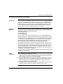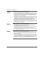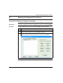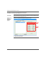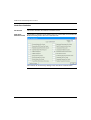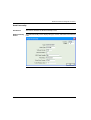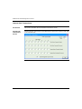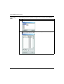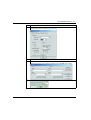
1
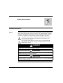
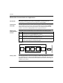
TSXCUSBMBP
USB Modbus Plus
Communications Adapter
User Manual
35011984 eng
2
Table of Contents
Safety Information . . . . . . . . . . . . . . . . . . . . . . . . . . . . . . . . . . . . 5
About the Book . . . . . . . . . . . . . . . . . . . . . . . . . . . . . . . . . . . . . . . 7
Chapter 1
Glossary of Abbreviations and Acronyms . . . . . . . . . . . . . . . . . 9
Glossary of Abbreviations and Acronyms . . . . . . . . . . . . . . . . . . . . . . . . . . . . . . . 9
Chapter 2
Overview . . . . . . . . . . . . . . . . . . . . . . . . . . . . . . . . . . . . . . . . . . . 11
At a Glance . . . . . . . . . . . . . . . . . . . . . . . . . . . . . . . . . . . . . . . . . . . . . . . . . . . . .
Modbus Plus Communication for Applications . . . . . . . . . . . . . . . . . . . . . . . . . .
Modbus Plus Network Diagnostics . . . . . . . . . . . . . . . . . . . . . . . . . . . . . . . . . . .
TSXCUSBMBP Hardware . . . . . . . . . . . . . . . . . . . . . . . . . . . . . . . . . . . . . . . . . .
Chapter 3
Installation. . . . . . . . . . . . . . . . . . . . . . . . . . . . . . . . . . . . . . . . . . 15
At a Glance . . . . . . . . . . . . . . . . . . . . . . . . . . . . . . . . . . . . . . . . . . . . . . . . . . . . .
Installation Requirements . . . . . . . . . . . . . . . . . . . . . . . . . . . . . . . . . . . . . . . . . .
Upgrading From Previous Version . . . . . . . . . . . . . . . . . . . . . . . . . . . . . . . . . . .
Installing the TSXCUSBMBP Driver Software. . . . . . . . . . . . . . . . . . . . . . . . . . .
Installing the TSXCUSBMBP Hardware . . . . . . . . . . . . . . . . . . . . . . . . . . . . . . .
Chapter 4
11
12
13
13
15
16
16
17
17
Establishing a Connection to the TSXCUSBMBP . . . . . . . . . . 19
At a Glance . . . . . . . . . . . . . . . . . . . . . . . . . . . . . . . . . . . . . . . . . . . . . . . . . . . . . 19
Rescan Adapters. . . . . . . . . . . . . . . . . . . . . . . . . . . . . . . . . . . . . . . . . . . . . . . . . 20
Show Interface . . . . . . . . . . . . . . . . . . . . . . . . . . . . . . . . . . . . . . . . . . . . . . . . . . 20
Chapter 5
Configuring the TSXCUSBMBP Driver . . . . . . . . . . . . . . . . . . . 21
At a Glance . . . . . . . . . . . . . . . . . . . . . . . . . . . . . . . . . . . . . . . . . . . . . . . . . . . . .
The TSXCUSBMBP Driver Interface Window . . . . . . . . . . . . . . . . . . . . . . . . . . .
Configuring the Modbus Plus Node Address . . . . . . . . . . . . . . . . . . . . . . . . . . .
Configuring the Slave Response Timeout. . . . . . . . . . . . . . . . . . . . . . . . . . . . . .
Configuring the Virtual Serial (COM) Port . . . . . . . . . . . . . . . . . . . . . . . . . . . . . .
Configuring the Modbus Plus Routing. . . . . . . . . . . . . . . . . . . . . . . . . . . . . . . . .
21
22
23
24
26
27
3
Chapter 6
Connecting to a Modbus Plus Network . . . . . . . . . . . . . . . . . . 33
Modbus Plus Network Status Indicator . . . . . . . . . . . . . . . . . . . . . . . . . . . . . . . . 33
Chapter 7
Using the TSXCUSBMBP with an Application . . . . . . . . . . . . 35
Overview . . . . . . . . . . . . . . . . . . . . . . . . . . . . . . . . . . . . . . . . . . . . . . . . . . . . . . . 35
Start the TSXCUSBMBP Driver . . . . . . . . . . . . . . . . . . . . . . . . . . . . . . . . . . . . . . 36
Configure the Application Software . . . . . . . . . . . . . . . . . . . . . . . . . . . . . . . . . . . 37
Connect!. . . . . . . . . . . . . . . . . . . . . . . . . . . . . . . . . . . . . . . . . . . . . . . . . . . . . . . . 37
Chapter 8
8.1
8.2
8.3
Appendices
Modbus Plus Network Diagnostic Functions . . . . . . . . . . . . . 39
At a Glance . . . . . . . . . . . . . . . . . . . . . . . . . . . . . . . . . . . . . . . . . . . . . . . . . . . . . 39
Starting the Diagnostic Functions . . . . . . . . . . . . . . . . . . . . . . . . . . . . . . . . . . . . 41
Procedure for Starting the Diagnostic Functions . . . . . . . . . . . . . . . . . . . . . . . . . 41
Scanning the Modbus Plus Network . . . . . . . . . . . . . . . . . . . . . . . . . . . . . . . . . . 42
Procedure for Scanning the Modbus Plus Network . . . . . . . . . . . . . . . . . . . . . . . 42
Displaying Diagnostic Information . . . . . . . . . . . . . . . . . . . . . . . . . . . . . . . . . . . . 43
At a Glance . . . . . . . . . . . . . . . . . . . . . . . . . . . . . . . . . . . . . . . . . . . . . . . . . . . . . 43
Procedure for Displaying Diagnostic Information. . . . . . . . . . . . . . . . . . . . . . . . . 44
Node Error Statistics . . . . . . . . . . . . . . . . . . . . . . . . . . . . . . . . . . . . . . . . . . . . . . 46
Node Personality . . . . . . . . . . . . . . . . . . . . . . . . . . . . . . . . . . . . . . . . . . . . . . . . . 47
Internal Path Transactions . . . . . . . . . . . . . . . . . . . . . . . . . . . . . . . . . . . . . . . . . . 48
Token Owner Work Table . . . . . . . . . . . . . . . . . . . . . . . . . . . . . . . . . . . . . . . . . . 49
Active Station Table. . . . . . . . . . . . . . . . . . . . . . . . . . . . . . . . . . . . . . . . . . . . . . . 50
Token Station Table. . . . . . . . . . . . . . . . . . . . . . . . . . . . . . . . . . . . . . . . . . . . . . . 51
Global Data Present Table. . . . . . . . . . . . . . . . . . . . . . . . . . . . . . . . . . . . . . . . . . 52
Read Global Data . . . . . . . . . . . . . . . . . . . . . . . . . . . . . . . . . . . . . . . . . . . . . . . . 53
. . . . . . . . . . . . . . . . . . . . . . . . . . . . . . . . . . . . . . . . . . . . . . . 55
At a Glance . . . . . . . . . . . . . . . . . . . . . . . . . . . . . . . . . . . . . . . . . . . . . . . . . . . . . 55
Appendix A
TSXCUSBMBP Settings for Unity. . . . . . . . . . . . . . . . . . . . . . . 57
TSXCUSBMBP Settings for Unity . . . . . . . . . . . . . . . . . . . . . . . . . . . . . . . . . . . . 57
Appendix B
TSXCUSBMBP Settings for Concept & ProWORX32 . . . . . . . 61
TSXCUSBMBP Settings for Concept & ProWORX32 . . . . . . . . . . . . . . . . . . . . . 61
4
Safety Information
§
Important Information
NOTICE
Read these instructions carefully, and look at the equipment to become familiar with the
device before trying to install, operate, or maintain it. The following special messages
may appear throughout this documentation or on the equipment to warn of potential
hazards or to call attention to information that clarifies or simplifies a procedure.
The addition of this symbol to a Danger or Warning safety label indicates
that an electrical hazard exists, which will result in personal injury if the
instructions are not followed.
This is the safety alert symbol. It is used to alert you to potential personal
injury hazards. Obey all safety messages that follow this symbol to avoid
possible injury or death.
DANGER
DANGER indicates an imminently hazardous situation, which, if not avoided, will
result in death, serious injury, or equipment damage.
WARNING
WARNING indicates a potentially hazardous situation, which, if not avoided, can result
in death, serious injury, or equipment damage.
CAUTION
CAUTION indicates a potentially hazardous situation, which, if not avoided, can result
in injury or equipment damage.
35011984 02/2006
5
Safety Information
PLEASE NOTE
Electrical equipment should be serviced only by qualified personnel. No responsibility is
assumed by Schneider Electric for any consequences arising out of the use of this
material. This document is not intended as an instruction manual for untrained persons.
© 2006 Schneider Electric. All Rights Reserved.
6
35011984 02/2006
About the Book
At a Glance
Document Scope
This document provides an installation, setup and usage guide for the Schneider
Automation TSXCUSBMBP (USB Modbus Plus) communications adapter.
It describes the basic procedures required to
z install the hardware,
It describes the basic procedures required to install the hardware, install and
configure the driver software, access the TSXCUSBMBP from a software application,
and use the Modbus Plus network diagnostics features of the driver software.
z install and configure the driver software,
z access the TSXCUSBMBP from a software application, and
z use the Modbus Plus network diagnostics features of the driver software.
Validity Note
The information in this manual is applicable only for TSXCUSBMBP
communications adapters.
Product Related
Warnings
Schneider Electric assumes no responsibility for any errors that appear in this
document. No part of this document may be reproduced in any form or means,
including electronic, without prior written permission of Schneider Electric.
User Comments
We welcome your comments about this document. You can reach us by e-mail at
[email protected]
35011984 02/2006
7
About the Book
8
35011984 02/2006
Glossary of Abbreviations and
Acronyms
1
Glossary of Abbreviations and Acronyms
Introduction
This glossary provides an expansion of abbreviations and acronyms used in this
documentation.
Glossary of
Abbreviations
and Acronyms
The following table lists all abbreviations and acronyms and their respective
expansions.
35011984 02/2006
Abbreviation/Acronym
Expansion
MBP
Modbus Plus
MB+
Modbus Plus
MODBUS+
Modbus Plus
USB
Universal Serial Bus
VSP
Virtual Serial Port
WinNT
Windows NT
WinXP
Windows XP
SP2
Service Pack 2
Win2k
Windows 2000
9
Abbreviations & Acronyms
10
35011984 02/2006
Overview
2
At a Glance
Subject of this
chapter
The TSXCUSBMBP communications adapter is designed to provide a bridge between a
simple and inexpensive USB connection and a Modbus Plus Network. The device is a
combination of hardware (TSXCUSBMBP) and software drivers (TSXCUSBMBP Driver
and Virtual Serial Port) that operate together as a single entity.
The TSXCUSBMBP has its own Modbus Plus Node Address on the Modbus Plus
network, which is set via the TSXCUSBMBP Driver software.
The TSXCUSBMBP provides two areas of functionality. The first one allows
software applications using serial Modbus RTU communications to communicate on
a highspeed Modbus Plus network. The second one provides diagnostic tools for a
Modbus Plus network.
What's in this
Chapter?
35011984 02/2006
This chapter contains the following topics:
Topic
Page
Modbus Plus Communication for Applications
12
Modbus Plus Network Diagnostics
13
TSXCUSBMBP Hardware
13
11
Overview
Modbus Plus Communication for Applications
Introduction
Most Win32 applications that support serial Modbus communications can
communicate on a Modbus Plus network with the TSXCUSBMBP.
Virtual Serial
Port (VSP)
A Virtual Serial Port (VSP) is used as the mechanism for redirecting communications
from programs such as Concept, Unity, and ProWorx32 to the TSXCUSBMBP
adapter. The VSP presents the same interface as a standard serial port to the
software. As such it is indistinguishable from a physical serial port.
Modbus Plus
CommunicationProcess
The Modbus Plus Communication process is described in the following table:
Stage Description
1
After the VSP is installed, it will create one serial port with the port reference (COM1COM12) defined in the TSXCUSBMBP Driver software.
2
When configuring the Modbus application software, this port reference for the VSP
is selected as the serial port for the application to use.
3
The TSXCUSBMBP Driver will then work like a Bridge Multiplexer to redirect serial
Modbus Plus messages onto a Modbus Plus network, but at a much faster rate since
no serial communications are actually taking place.
Illustration:
Windows XP
Operating System
Routing Table
12
Virtual
Serial Port
Driver
TSX C
USB MBP
Driver
USB-MBP
Driver
USB
Controller
USB
Cable
USB-MBP
Modbus Plus Network
Application
Software
A routing table similar to that used by Modicon's BM85 Bridge Multiplexer is used to
associate Modbus Slave IDs with 5-byte Modbus Plus routing paths. This allows the
application software to communicate with any Modbus Plus device within range on
a Modbus Plus network.
35011984 02/2006
Overview
Modbus Plus Network Diagnostics
TSXCUSBMBP
The TSXCUSBMBP provides a diagnostic tool for Modbus Plus networks. It has the
same basic functionality as the MBPSTAT program but adds the ability to scan a
complete Modbus Plus network.
TSXCUSBMBP Hardware
Description
The TSXCUSBMBP consists of a box with a USB cable extending from one end for
connection to a PC, and a standard Modbus Plus DB9 connector on the other end
for connection to a Modbus Plus network.
LEDs in the top cover of the device indicate the presence of power from the USB port
and the status of the Modbus Plus connection. No external power supply is needed.
35011984 02/2006
USB
MODBUS PLUS
ODBUS PLUS STATUS
Modbus Plus Cable
POWER
Illustration
PC
USB
Port
13
Overview
14
35011984 02/2006
Installation
3
At a Glance
Subject of this
chapter
This section describes the procedures required to install the TSXCUSBMBP Driver
software and the TSXCUSBMBP communications adapter.
Note: Do not attach the TSXCUSBMBP device to a USB port until installation of
the Driver Software is complete.
What's in this
Chapter?
35011984 02/2006
This chapter contains the following topics:
Topic
Page
Installation Requirements
16
Upgrading From Previous Version
16
Installing the TSXCUSBMBP Driver Software
17
Installing the TSXCUSBMBP Hardware
17
15
Installation
Installation Requirements
Installation
Requirements
list
Installation requirements are as follows:
z Microsoft Windows XP Operating System with Service Pack 2 or greater installed
(Windows 2000 with Service Pack 4 or greater can also be used on most
computers),
z 1 MB free disk space,
z at least 256 MB RAM,
z at least one free USB port or a USB Hub supporting USB 1.1 or greater.
Upgrading From Previous Version
Introduction
Currently, if a previous version of the TSXCUSBMBP Driver has been installed, the
Virtual Serial Port component of the driver must be manually uninstalled using
Device Manager before a new version can be installed.
How to uninstall
the Virtual Serial
Port?
These steps must be followed to uninstall the Virtual Serial Port from your system.
16
Step Action
1
Close any software applications using the TSXCUSBMBP Driver.
2
Exit the TSXCUSBMBP Driver by right clicking on the Icon at the bottom then
selecting Exit Driver.
3
Unplug the USB Modbus Plus Device from the USB port on the computer (or USB
Hub if using one).
4
Start up the Windows Device Manager.
On most systems, this is done by the following steps.
z Open Control Panel, System, Hardware, then Device Manager.
z In Device Manager, left click on the + next to ABT Virtual Device. Virtual Serial
Port will now appear underneath ABT Virtual Device.
z Right click on Virtual Serial Port and select Uninstall.
z When prompted, confirm the device removal.
z After ABT Virtual Device disappears from the list, close the Device Manager.
35011984 02/2006
Installation
Installing the TSXCUSBMBP Driver Software
Introduction
The TSXCUSBMBP Driver must be installed before connecting the TSXCUSBMBP
device to the USB port.
How to install the
TSXCUSBMBP
Driver?
Use the following procedure to install the Driver software.
Step Action
1
Insert the CD-ROM labeled TSXCUSBMBP Driver into your CD-ROM drive.
2
The installation should begin automatically. If not, follow the procedure below to start
the installation manually.
z From the Start menu (Start button on Windows XP task bar), select Run
z Type in D:\Setup.exe (if your CD-ROM drive is not D:, substitute the drive letter of
your CD-ROM drive) and press Ok.
3
Follow the on-screen instructions to complete the software installation.
4
The final step of the software installation will display a message window containing
instructions. Please read the instructions carefully.
Installing the TSXCUSBMBP Hardware
Introduction
The TSX C USB MBP can be connected directly to a USB port on the PC or
through a USB Hub. The TSXCUSBMBP acquires power from the USB port or Hub,
therefore no power connection is required.
Note: Do not connect the Modbus Plus network cable to the Modbus Plus port on
the TSXCUSBMBP until after the Modbus Plus Node Address has been configured
in the Driver Software. This will avoid the potential for duplicate Modbus Plus node
addresses on your network.
35011984 02/2006
17
Installation
How to install the
TSXCUSBMBP
Hardware
18
Use the following procedure to install the TSXCUSBMBP hardware.
Step Action
1
After installing the TSXCUSBMBP Driver software, insert the USB cable from the
TSXCUSBMBP into a USB port on the PC or into a USB Hub connected to the PC.
Once the TSXCUSBMBP is connected to the PC or Hub, the Power LED on the
TSXCUSBMBP will light. This indicates that the TSXCUSBMBP is getting power from
the USB port or Hub.
2
If this is the first time the TSXCUSBMBP has ever been connected to the USB port or Hub,
the Found New Hardware message will pop up and the New Hardware Wizard will start
up. If this occurs, follow these steps to complete the hardware installation:
z Select No, not this time when the message Can Windows connect to Windows
Update pops up, then click on Next.
z Select Install the software automatically (Recommended) when the message
What do you want the wizard to do? pops up, then click on Next.
z If the message The software you are installing has not passed Windows Logo
Testing pops up, select Continue Anyway. When finished, click on Finish.
z The Found New Hardware message will pop up again followed by the New
Hardware Wizard.
z Select No, not this time when the message Can Windows connect to Windows
Update pops up, then click on Next.
z Select Install the software automatically (Recommended) when the message
What do you want the wizard to do? pops up, then click on Next.
z If the message The software you are installing has not passed Windows Logo
Testing pops up, select Continue Anyway.
z When the wizard has finished installing the software, click on Finish.
z Wait for the Found New Hardware message to pop up with Your new hardware
is ready to use.
3
Restart the computer.
35011984 02/2006
Establishing a Connection to the
TSXCUSBMBP
4
At a Glance
Subject of this
chapter
The TSXCUSBMBP Driver is added to the Startup group during installation. After restarting
the computer at the end of the hardware installation, the driver will automatically start and will
continue to do so each time the computer is powered up or restarted.
If the TSXCUSBMBP Driver is ever removed from the Startup menu, you will need to
start the driver manually by going to the Programs menu and selecting Schneider Electric
then TSXCUSBMBP then TSXCUSBMBP Driver. The TSXCUSBMBP Driver allows for
only one instance of it to run at any time, so starting it multiple times is not a concern.
Status of the
Driver
When the TSXCUSBMBP Driver is running, an icon will appear in the system tray of
the computer to indicate the status of the driver, as shown in the table below.
Icon
What's in this
Chapter?
35011984 02/2006
Color
Status of the driver
normal
A TSXCUSBMBP was found.
red
No TSXCUSBMBP was found.
yellow
A TSXCUSBMBP was found, and is in the process of initializing and
connecting to a Modbus Plus network.
This chapter contains the following topics:
Topic
Page
Rescan Adapters
20
Show Interface
20
19
Establishing a Connection
Rescan Adapters
Introduction
If the TSXCUSBMBP device was not connected to the PC when the TSXCUSBMBP
Driver started up, it will be necessary to rescan for a connected TSXCUSBMBP adapter
before the driver will detect its presence. A red icon in the system tray will indicate this.
How to rescan?
To rescan, right click on the icon in the system tray and select Rescan Adapters. The
driver should then find the TSXCUSBMBP, and the icon will turn yellow for several
seconds while the TSXCUSBMBP initializes and listens to the Modbus Plus
network. It will then go to normal operation.
If the icon
remains red...
If the icon in the tray remains red following a rescan, check your USB connection and
make sure the appropriate USB drivers are installed and enabled on your computer.
Show Interface
Introduction
As long as the TSXCUSBMBP driver is running, the driver Interface Window can be
displayed to show driver configuration and connection information. It does not matter
if the TSXCUSBMBP driver has established a connection with the TSXCUSBMBP
device or not (the color of the icon in the system tray does not matter).
How to display
the Interface
Window?
To display the Interface Window, right click on the icon in the tray and select
Show Interface.
20
35011984 02/2006
Configuring the TSXCUSBMBP
Driver
5
At a Glance
Subject of this
Chapter
This chapter describes how to configure the TSXCUSBMBP driver.
What's in this
Chapter?
This chapter contains the following topics:
35011984 02/2006
Topic
Page
The TSXCUSBMBP Driver Interface Window
22
Configuring the Modbus Plus Node Address
23
Configuring the Slave Response Timeout
24
Configuring the Virtual Serial (COM) Port
26
Configuring the Modbus Plus Routing
27
21
Configuring the TSXCUSBMBP Driver
The TSXCUSBMBP Driver Interface Window
Introduction
The Interface Window is used to configure the TSXCUSBMBP driver and device. It
also has a message area where status and error information is displayed.
Interface
Window Display
To display the Interface Window:
z right click on the TSXCUSBMBP icon in the system tray and
z select Show Interface.
The Interface Window is displayed hereunder:
22
35011984 02/2006
Configuring the TSXCUSBMBP Driver
Configuring the Modbus Plus Node Address
Address
Assignment
The TSXCUSBMBP communications adapter must be assigned a Modbus Plus
Node Address in order to communicate on the Modbus Plus network.
The Modbus Plus Node Address assignment window is displayed:
Address
Configuration
Address
Changing
Process
To configure the Modbus Plus Node Address of the TSXCUSBMBP device:
Step
Action
1
Select Settings from the top level menu of the TSXCUSBMBP Driver Interface Window
2
Type the new address into the field labeled Modbus+ Node Address
3
Click on the Save button to save the new address.
After the Save button is pressed, the process of changing the Modbus+ Node
address of the TSXCUSBMBP device will begin.
To complete this process, the TSXCUSBMBP device must be reinitialized.
z
z
An information window will pop up, designating that the node address is being
changed, and it will take approximately 10 seconds to complete the process.
Click on OK to exit the information window.
The Settings Menu will remain disabled until the process of changing the node
address is complete.
After the process has completed, the Modbus Plus cable can be connected to the
TSXCUSBMBP device without risk of a duplicate Modbus+ node address on the network.
35011984 02/2006
23
Configuring the TSXCUSBMBP Driver
Configuring the Slave Response Timeout
Introduction
The Slave Response Timeout is used by the TSXCUSBMBP each time it sends a
request from an application out the Modbus Plus network to a slave device.
Slave Response
Timeout
This timeout is variable due to the possibility of a radio link or serial link somewhere
in between the TSXCUSBMBP device and the slave device it is communicating with:
z The interface between the application and the TSXCUSBMBP driver has the
same characteristics of an actual serial port.
z One request must be completed before another request can be sent out.
z If the slave device does not respond to the TSXCUSBMBP, it must time out from
waiting on the response before it can accept another request from the application.
Timeout Value
The value for the Slave Response Timeout needs to be determined by adding
together the following times:
1. The maximum amount of time it can take for a request to be sent to any slave
device that the TSXCUSBMBP will be communicating with. This time must
include any delays induced by modems, RF links, network bridges, etc.
2. The maximum amount of time it can take for any slave device to process a request.
Note: Start operations on certain PLCs can take as long as 4 seconds or more to
process. If the Slave Response Timeout value is lower than this, timeouts may occur.
3. The maximum amount of time it can take for a response to be sent from any slave
device back to the TSXCUSBMBP. This time must include any delays induced by
modems, RF links, network bridges, etc.
4. Some additional time to provide a ‘safety zone’ to allow for the ‘unexpected’. A
value of 500 ms is adequate if all slave devices are connected on the local
Modbus Plus network or through a high-speed bridge. If any slower network
interfaces are in the communication path between the TSXCUSBMBP and any
slave device, an adequate value is usually between 1000 and 2000 ms.
Note: When performing a Modbus network scan using ProWorx or Concept,
changing the Slave Response Timeout value from its default of 5000 ms to
600 ms before the scan will greatly improve performance. However, the Slave
Response Timeout must be set back to the proper value before attaching to a
PLC in programming mode and performing Start operations.
24
35011984 02/2006
Configuring the TSXCUSBMBP Driver
Timeout
Configuration
Once the appropriate value has been determined, the Slave Response Timeout is
configured as follows:
Step
Timeout Saving
Action
1
Select Settings from the top level menu of the TSXCUSBMBP Driver Interface Window.
2
Type the appropriate timeout value into the field labeled Slave Response Timeout.
3
Click on the Save button to save the new Slave Response Timeout.
A new Slave Response Timeout saving window is displayed:
Note: When the Save button is pressed, the new timeout setting will take effect
immediately.
35011984 02/2006
25
Configuring the TSXCUSBMBP Driver
Configuring the Virtual Serial (COM) Port
Introduction
The Virtual Serial Port used by the application to send Modbus requests to the
TSXCUSBMBP Driver will default to COM3 during installation.
COM3
Assignment
If another device is already installed on COM3, the Virtual Serial Port will need to
be changed.:
If...
Then...
another device is already installed on COM3 the Virtual Serial Port will need to be changed
Port Changing
26
To change the port reference for the Virtual Serial Port in the application:
1
If an application is open that is using the Virtual Serial Port to communicate with the
TSXCUSBMBP, it should be closed.
2
Select Virtual Modbus Port from the top level menu on the TSXCUSBMBP Driver
Interface Window.
3
Select the desired COM port from the list of available COM ports.
4
Click on the Save button to save the new setting.
Note: The new setting will take effect immediately upon pressing the Save button.
The application being used with the TSXCUSBMBP must be configured to
communicate using the serial port configured here.
35011984 02/2006
Configuring the TSXCUSBMBP Driver
Configuring the Modbus Plus Routing
Introduction
When interfacing to an application through the Virtual Serial Port, the TSXCUSBMBP
operates as a serial Modbus to Modbus Plus converter, similar to the BM85 Bridge
Multiplexer. The Virtual Serial Port captures serial Modbus RTU messages sent by a
Modbus application and redirects them to the TSXCUSBMBP driver. The driver then
converts each message from the Modbus RTU format into the Modbus Plus format
before sending it out onto the network and waiting for a response.
Addressing
Methods
When converting a Modbus RTU request to Modbus Plus, the driver must convert a
single Modbus ID into a 5-byte Modbus Plus routing path. The TSXCUSBMBP driver
supports three different methods of doing this:
1. Explicit Addressing,
2. Direct Addressing,
3. Implicit Addressing.
The first method, known as Explicit Addressing, uses the TSXCUSBMBP driver's
Modbus Routing Table. A unique Modbus ID (also known as Modbus Slave Address
or Modbus Slave ID) is assigned by the user to each Modbus Plus device that will
be accessed from a Modbus application. An entry is then made into the Modbus
Routing Table that specifies the Modbus Plus Routing path to use whenever a
Modbus application sends a Modbus RTU message to that Modbus ID.
The second and third methods use the value of the Modbus ID to generate the
Modbus Plus routing path according to a predefined set of rules. These methods
include Direct Addressing and Implicit Addressing, where the actual addressing type
used is determined by the range of values that the Modbus ID falls into. Direct
Addressing and Implicit Addressing are only used when an entry does not exist in
the Modbus Routing Table for a Modbus ID.
The Explicit, Direct, and Implicit addressing methods are the same methods used by
the BM85 Bridge Multiplexer.
Before
configuring
Before configuring the Modbus Plus routing
1. make a complete list of all Modbus Plus nodes that will be accessed from Modbus
applications. Do not include any Modbus Plus nodes that will be accessed only
with the Diagnostic functions of the TSXCUSBMBP,
2. determine which nodes can be accessed using Direct Addressing or Implicit
Addressing (see below). The Modbus Routing Table has a maximum size of 64
entries and using Direct or Implicit Addressing where possible will limit the
number of table entries that must be used,
3. assign Modbus IDs to all remaining Modbus Plus nodes before entering them into
the Modbus Routing Table where Explicit Addressing will be used.
35011984 02/2006
27
Configuring the TSXCUSBMBP Driver
1. Explicit
Addressing
The Explicit Addressing process is described as follows:
z Explicit Addressing is used whenever the Modbus ID in a message received
through the Virtual Serial Port is present in the Modbus Routing Table, regardless
of what range of values the Modbus ID falls into. In Explicit Addressing, the
routing path will be the one that was entered into the Modbus Routing Table for
the Modbus ID of the received message.
z Any value can be selected for the Modbus ID as long as it does not conflict with
any Modbus IDs currently used by the application for Direct Addressing or Implicit
Addressing. However, it is helpful for each Modbus ID to have some
correspondence in value to the Modbus Plus node that it will be used to access.
z If no Modbus Plus node addresses are duplicated in the network (same
Modbus Plus node address used on more than one local network if separated by
Bridge Plus devices), the Modbus IDs to use for Explicit Addressing can be the
actual Modbus Plus node addresses.
2. Direct
Addressing
The Direct Addressing process is described as follows:
z If the Modbus ID in a message received through the Virtual Serial Port is not
present in the Modbus Routing Table and it is in the range of 1-64, the
TSXCUSBMBP Driver will use Direct Addressing.
z In Direct Addressing, the Modbus ID of the received message is used directly as
the 1st byte of the routing path, and the remaining 4 bytes are set to 0.
z For example, a Modbus ID of 2 would be routed to [2.0.0.0.0], and a Modbus ID
of 45 would be routed to [45.0.0.0.0]
3. Implicit
Addressing
The Implicit Adressing process is described as follows:
z If the Modbus ID in a message received through the Virtual Serial Port is not
present in the Modbus Routing Table and it is in the range of 80-255, Implicit
Addressing will be used.
z When the TSXCUSBMBP driver uses Implicit Addressing, it divides the Modbus
ID of the received message by 10. The quotient is used as the 1st byte of the
routing path, the remainder is used as the 2nd byte of the routing path, and the
remaining 3 bytes are set to 0. For example, a Modbus ID of 87 would be routed
to [8.7.0.0.0], and a Modbus ID of 230 would be routed to [23.0.0.0.0].
28
35011984 02/2006
Configuring the TSXCUSBMBP Driver
Routing Example
5
TSXCUSB
Routing example:
15
16
23
43
PLC
PLC
Bridge
Plus
5
Bridge
Plus
PLC
6
10 PLC
9
20
1
2
3
20 Bridge
Plus
PLC
PLC
PLC
The following table shows the routing table entries that must be made to route
messages to the PLCs at Modbus Plus Node Addresses 1, 2, 3, 10, 15, and 16.
Modbus +
Node
Address
Slave ID
TSXCUSBMBP
used by
Routing Table
application Entry
Modbus Plus Routing Path
1
231
None Required
23.1.0.0.0 as determined through Implicit Addressing If desired, Explicit
Addressing could be used by selecting an unused Modbus ID and
placing an entry for that Modbus ID into the Routing Table going to
23.1.0.0.0
2
232
None Required
23.2.0.0.0 as determined through Implicit Addressing If desired, Explicit
Addressing could be used by selecting an unused Modbus ID and
placing an entry for that Modbus ID into the Routing Table going to
23.2.0.0.0
3
233
None Required
23.3.0.0.0 as determined through Implicit Addressing If desired, Explicit
Addressing could be used by selecting an unused Modbus ID and
placing an entry for that Modbus ID into the Routing Table going to
23.3.0.0.0
6
26
Modbus ID 26,
Routing Path
23.20.6.0.0
23.20.6.0.0 as determined through Explicit Addressing from the
Modbus Routing Table
10
10
Modbus ID 10,
Routing Path
43.10.0.0.0
43.10.0.0.0 as determined through Explicit Addressing from the
Modbus Routing Table
35011984 02/2006
29
Configuring the TSXCUSBMBP Driver
Modbus +
Node
Address
30
Slave ID
TSXCUSBMBP
used by
Routing Table
application Entry
Modbus Plus Routing Path
15
15
None Required
15.0.0.0.0 as determined through Direct AddressingIf desired, Explicit
Addressing could be used by selecting an unused Modbus ID and
placing an entry for that Modbus ID into the Routing Table going to
15.0.0.0.0
16
16
None Required
16.0.0.0.0 as determined through Direct AddressingIf desired, Explicit
Addressing could be used by selecting an unused Modbus ID and
placing an entry for that Modbus ID into the Routing Table going to
16.0.0.0.0
35011984 02/2006
Configuring the TSXCUSBMBP Driver
Entering Routing
Paths into the
Routing Table
Use the following procedure to change an entry in the Routing Table:
Step Action
1
Select Routing from the top level menu on the TSXCUSBMBP Driver Interface window.
2
Select the entry to be changed in the table by left clicking on it (the entry will become
highlighted)
3
Enter the Modbus ID and the associated Modbus Plus Routing Path in the fields below
the table.
4
Click on the Update button to update that entry in the table. You will see the entry in
the table above change to the new values.
5
Repeat steps 2-4 for each entry to change in the Routing table.
Note: Clicking on the Close button will save all Routing Table entries and return to the
top level menu. The new Routing Table will take effect immediately.
35011984 02/2006
31
Configuring the TSXCUSBMBP Driver
32
35011984 02/2006
Connecting to a Modbus Plus
Network
6
Modbus Plus Network Status Indicator
Introduction
The Modbus Plus Network Status Indicator displays the status of the Modbus Plus
communications on the TSXCUSBMBP device.
During initial monitoring of the network, the Indicator will flash at approximately 1
time/second. If successful Modbus Plus communications are established, it will flash
more rapidly, approximately 6 times/second. Otherwise, it will flash an error code,
indicating that there is a problem with the connection.
Flash Codes
35011984 02/2006
The table below indicates the valid flash codes for the Modbus Plus Network Status
Indicator:
LED Flash Code
Description
6 flashes/second
The TSXCUSBMBP is successfully receiving and passing the token on
the Modbus Plus network. This is the normal operating mode for a node
on a Modbus Plus network.
1 flash/second
The TSXCUSBMBP is offline, and monitoring the Modbus Plus network to
determine which nodes are active prior to attempting to join the network.
2 flashes, then
pause
The TSXCUSBMBP can hear the token being passed, but never
receives the token.
3 flashes, then
pause
The TSXCUSBMBP cannot hear the token being passed. This is the
flash code to expect if the Modbus Plus cable is not connected to the
TSXCUSBMBP.
4 flashes, then
pause
The TSXCUSBMBP has detected another node on the Modbus Plus
network using the same node address as the TSXCUSBMBP. The
TSXCUSBMBP will remain in this state until it has not heard any messages
from any other node with the same node address for at least 5 seconds.
33
Connecting to a Modbus Plus Network
34
35011984 02/2006
Using the TSXCUSBMBP with an
Application
7
Overview
The
TSXCUSBMBP
with an
Application
The TSXCUSBMBP is designed to interface with any Win32 application software
that communicates using serial Modbus RTU over a user-selectable COM port. The
application must be running under Windows XP or in some cases, Windows 2000.
The following general procedure can be used with any applicable application
software.
Note: Refer to the appendix for more detailed instructions on using the
TSXCUSBMBP with Unity, Concept and Proworx32.
What's in this
Chapter?
35011984 02/2006
This chapter contains the following topics:
Topic
Page
Start the TSXCUSBMBP Driver
36
Configure the Application Software
37
Connect!
37
35
Using the TSXCUSBMBP with an Application
Start the TSXCUSBMBP Driver
Introduction
Before an application can communicate through the TSXCUSBMBP, the
TSXCUSBMBP Driver must:
z be running, and
z be connected to a TSXCUSBMBP device.
Note: See Sections 4 and 5 of this User's Guide for more information on installing
and setting up the TSXCUSBMBP Driver.
36
35011984 02/2006
Using the TSXCUSBMBP with an Application
Configure the Application Software
Introduction
Because the software interface to the TSXCUSBMBP uses a Virtual Serial Port, it is
relatively simple to configure an application to use it for communications.
A Typical
Configuration
The following steps illustrate a typical configuration:
Step Action
1
Determine which serial (COM) port the TSXCUSBMBP Driver is using.
This information is displayed automatically whenever the mouse hovers over the
TSXCUSBMBP Driver icon in the system tray, as shown in the example below:
TSXCUSBMBP
(Device Status)
Port: COM3
2
In the application's configuration, select the serial port shown (COM3 in the example
above).
Note: Don't worry about Baud Rate, Parity, etc. - the Virtual Serial Port ignores those
settings.
3
Select standard Modbus RTU for the protocol.
Connect!
Introduction
35011984 02/2006
Tell the application software to connect, just as if it were connecting to a hardware
serial port. The TSXCUSBMBP Driver will handle the rest.
37
Using the TSXCUSBMBP with an Application
38
35011984 02/2006
Modbus Plus Network Diagnostic
Functions
8
At a Glance
Subject of this
Chapter
This chapter describes the Modbus Plus network diagnostic functions.
What's in this
Chapter?
This chapter contains the following sections:
35011984 02/2006
Section
Topic
Page
8.1
Starting the Diagnostic Functions
41
8.2
Scanning the Modbus Plus Network
42
8.3
Displaying Diagnostic Information
43
39
Modbus Plus Network Diagnostic Functions
40
35011984 02/2006
Modbus Plus Network Diagnostic Functions
8.1
Starting the Diagnostic Functions
Procedure for Starting the Diagnostic Functions
Introduction
This section describes how to start the diagnostic functions of the TSXCUSBMBP.
Procedure
To start the diagnostic functions of the TSXCUSBMBP proceed as follows:
Step Action
35011984 02/2006
1
Right click on the TSXCUSBMBP Icon in the system tray.
2
Select Show Interface.
Result: the Interface Window of the TSXCUSBMBP driver opens.
3
Left click on the MB+ Network Diags heading on the top-level menu.
Result: the Modbus Plus Network Diagnostics screen will then be displayed:
41
Modbus Plus Network Diagnostic Functions
8.2
Scanning the Modbus Plus Network
Procedure for Scanning the Modbus Plus Network
Introduction
When the Diagnostics screen is first displayed, the only node that will appear in the
list of Modbus Plus Network nodes is the TSXCUSBMBP device itself. A Scan
function is used to locate other nodes on the network.
Scanning Local
or Complete
Network
A scan can be done on either the local Modbus Plus network or the complete
Modbus Plus network.
z
z
Modbus ID Field
42
When scanning the local network, Bridge Plus devices will be shown in the list but
no scanning will be done on the second network connection on the Bridge Plus.
When the complete Modbus Plus network is scanned, every Modbus Plus device
accessible from the TSXCUSBMBP device will be shown.
Note: The complete network scan is performed as follows:
z The system sequentially queries each address.
z The system sends a query to address 1. If a reponse is obtained, the
information is displayed and the system sends a request to the next address.
If the device is not connected to the network the system waits for a defined
timeout period before moving on to the next address.
z Address polling may be time consuming. For example, depending on the
network arcitecture (number of devices connected or disconnected) identifying
247 devices can take up to 12 minutes.
If a node displayed in the scan list has been entered into the routing table used by
application software to route messages for a specific Modbus ID to that
Modbus Plus node, the Modbus ID used by the application will be shown in the
Modbus ID field for that node.
35011984 02/2006
Modbus Plus Network Diagnostic Functions
8.3
Displaying Diagnostic Information
At a Glance
Introduction
This section describes the diagnostic information that can be displayed for each node.
What's in this
Section?
This section contains the following topics:
35011984 02/2006
Topic
Page
Procedure for Displaying Diagnostic Information
44
Node Error Statistics
46
Node Personality
47
Internal Path Transactions
48
Token Owner Work Table
49
Active Station Table
50
Token Station Table
51
Global Data Present Table
52
Read Global Data
53
43
Modbus Plus Network Diagnostic Functions
Procedure for Displaying Diagnostic Information
Introduction
After the Modbus Plus network has been scanned, the nodes are displayed in the
Modbus Plus Network Diagnostics screen.
Modbus Plus
Network
Diagnostics
Screen
Structure of the Modbus Plus Network Diagnostics screen:
1
2
1
2
44
Node Selected for Display field.
Diagnostic data types buttons.
35011984 02/2006
Modbus Plus Network Diagnostic Functions
Procedure
To display the diagnostic information from a node proceed as follows:
Step Action
35011984 02/2006
1
Select the node to display diagnostic information from by scrolling to it in the list and
clicking the mouse on it.
Results:
z the node is highlighted,
z the routing path for that item is shown in the Node Selected for Display field.
2
Click on the appropriate diagnostic data types button (Node Error Statistics, Node
Personality, Read Global Data, etc.)
Result: the information is read from the selected node and displayed in a new screen.
Note: the data on that screen is continually updated as long as the screen is open.
45
Modbus Plus Network Diagnostic Functions
Node Error Statistics
Introduction
This section describes the Node Error Statistics screen.
Node Error
Statistics Screen
The Node Error Statistics screen displays the error counters that are returned in the
Modbus Plus diagnostics data for the selected node:
The counters can be cleared by clicking on the Clear Error Counters button.
46
35011984 02/2006
Modbus Plus Network Diagnostic Functions
Node Personality
Introduction
This section describes the Node Personality screen.
Node Personality
Screen
The Node Personality screen displays the type, version, and status of the selected
node:
35011984 02/2006
47
Modbus Plus Network Diagnostic Functions
Internal Path Transactions
Introduction
This section describes the Internal Path Transactions screen.
Internal Path
Transactions
Screen
The Internal Path Transactions screen displays the transaction counts for each path
in the selected node:
48
35011984 02/2006
Modbus Plus Network Diagnostic Functions
Token Owner Work Table
Introduction
Clicking on the Token Owner Work Table button displays the Node Token Owner Bit
Map screen. This section describes this screen.
Node Token
Owner Bit Map
Screen
The Node Token Owner Bit Map screen shows a bit map reflecting the current token
status of each path in the selected node. Each position in the bit map will be colored
green when active and gray when inactive:
35011984 02/2006
49
Modbus Plus Network Diagnostic Functions
Active Station Table
Introduction
This section describes the Active Station Table screen.
Active Station
Table Screen
The Active Station Table screen shows a bit map reflecting the status of each node
on the local network of the selected node. Each position in the bit map will be colored
green when active and gray when inactive:
50
35011984 02/2006
Modbus Plus Network Diagnostic Functions
Token Station Table
Introduction
This section describes the Token Station Table screen.
Token Station
Table Screen
The Token Station Table shows a bit map reflecting the token passing status of each
node on the local network of the selected node. Each position in the bit map will be
colored green when active and gray when inactive:
35011984 02/2006
51
Modbus Plus Network Diagnostic Functions
Global Data Present Table
Introduction
This section describes the Global Data Present Table screen.
Global Data
Present Table
Screen
The Global Data Present Table screen shows a bit map reflecting the Global data
status of each node on the local network of the selected node. Each position in the
bit map will be colored green when active and gray when inactive:
52
35011984 02/2006
Modbus Plus Network Diagnostic Functions
Read Global Data
Introduction
Clicking on the Read Global Data button displays the Global Data screen. This
section describes this screen.
Global Data
Screen
The Global Data screen is used to display the Global Data sent by the selected
node. If no Global Data is present for that node, the Global Data Words Read field
will contain a 0 and no data will be displayed in the data area:
35011984 02/2006
53
Modbus Plus Network Diagnostic Functions
54
35011984 02/2006
Appendices
At a Glance
Introduction
The following appendices describe the TSXCUSBMBP settings
z for Unity, and
z for Concept & ProWORX32.
What's in this
Appendix?
The appendix contains the following chapters:
35011984 02/2006
Chapter
Chapter Name
Page
A
TSXCUSBMBP Settings for Unity
57
B
TSXCUSBMBP Settings for Concept & ProWORX32
61
55
Appendices
56
35011984 02/2006
TSXCUSBMBP Settings for Unity
A
TSXCUSBMBP Settings for Unity
Introduction
This section describes how to configure Unity to work the TSXCUSBMBP.
Important
Information
If the serial Modbus driver for Unity comes up before the TSXCUSBMBP driver
during system startup, Unity will not work properly. The following steps will prevent
this situation from occurring:
Step
35011984 02/2006
Action
1
Close the Unity application if it is open.
2
Shut down Unity's serial Modbus driver by right-clicking on the Modbus driver's icon
in the system tray then selecting Close.
3
Start the Unity application. Unity will automatically restart its serial Modbus driver.
57
TSXCUSBMBP Settings for Unity
Configuring
Unity
58
The following steps are required to configure Unity to work the TSXCUSBMBP:
Step Action
1
Configure the USB MBP virtual COM port, as shown in the following window:
2
Set the routing parameters if needed: (With the settings shown I can use 55, 5, or 15
to connect to the same Unity PLC.)
35011984 02/2006
TSXCUSBMBP Settings for Unity
Step Action
35011984 02/2006
3
Install and make sure the Modbus Driver is running for Unity's Modbus
Communication. (This is used by Unity, OFS, etc.)
4
Configure the Modbus Driver to use the USB MBP Virtual port (COM3).
5
Setup Unity's PLC Address setting for Modbus01 (Modbus Driver), and the local
Modbus Plus address or the address as defined in the USB MBP routing table.
6
Make sure both drivers are running:
59
TSXCUSBMBP Settings for Unity
Step Action
7
60
You should now be able to Connect:
35011984 02/2006
TSXCUSBMBP Settings for
Concept & ProWORX32
B
TSXCUSBMBP Settings for Concept & ProWORX32
Introduction
This section describes how to configure Concept & ProWORX32 to work the
TSXCUSBMBP.
Setting the
Optimum Baud
Rate in Concept
When using serial Modbus communications with Concept, a delay of approximately
50 milliseconds occurs before each Modbus request is transmitted.
When using Concept with the TSXCUSBMBP, a serial interface must be selected.
Therefore, the overall throughput of the TSXCUSBMBP with Concept is only slightly
above that of a serial Modbus interface. Setting the baud rate in Concept to 19200
instead of the 9600 default will slightly improve performance.
Setting the
Optimum Baud
Rate in
ProWORX32
35011984 02/2006
When using serial Modbus communications with ProWORX32, there are no delays
inserted and the TSXCUSBMBP runs at the expected USB speed.
61
TSXCUSBMBP Settings for Concept & ProWORX32
Configuring
Concept &
ProWORX32
62
The following steps are required to configure Concept & ProWORX32 to work the
TSXCUSBMBP:
Step Action
1
Configure the USB MBP virtual COM port, as shown in the following window:
2
Set the routing parameters if needed: (With the settings shown I can use 55, 5, or 15
to connect to the same Unity PLC.)
3
Set Concept's or ProWORX 32's Protocol to Modbus.
4
Set the Device or Port to the port USB MBP Virtual port (COM3).
35011984 02/2006
TSXCUSBMBP Settings for Concept & ProWORX32
Step Action
5
Set the PLC Node or Modbus Address to the local Modbus Plus address or the
address as defined in the USB MBP routing table.
ProWORX32
Concept
35011984 02/2006
63