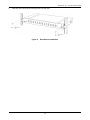
1
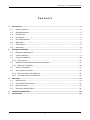
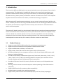
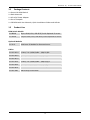
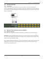
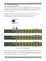
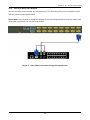
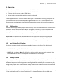
8 Port / 16 Port 1RU Rack Mount KVM Switch – VGA, USB & PS/2 Optional Remote IP Access User Manual Version 2.0.1 29-03-2013 ServerLink 8 / 16 Port KVM Switch Contents 1. Introduction.......................................................................................................................... 3 1.1 Product Features .................................................................................................................. 3 1.2 Package Contents ................................................................................................................. 4 1.3 Product Line ......................................................................................................................... 4 1.4 Front Panel ........................................................................................................................... 5 1.5 Port LED Indicators ............................................................................................................... 5 1.6 BANK LED ............................................................................................................................. 6 1.7 Push Buttons ........................................................................................................................ 6 1.8 Rear Panel ............................................................................................................................ 6 2. Hardware Installation ........................................................................................................... 7 2.1 Desktop or Rack Mount ....................................................................................................... 7 2.2 Cable Installation.................................................................................................................. 9 2.3 Console Installation ............................................................................................................ 10 2.3.1 Local Console ................................................................................................................. 10 2.4 Optional IP Based Remote Console Installation................................................................. 10 2.4.1 KVM over IP Module ...................................................................................................... 10 2.5 Power Up Sequence ........................................................................................................... 11 2.6 Daisy Chain Connection ..................................................................................................... 12 2.6.1 Bus Layer Daisy Chain Method ....................................................................................... 12 2.6.2 Tree Layer Daisy Chain Method ..................................................................................... 13 3. Operation ........................................................................................................................... 14 3.1 DDC function ...................................................................................................................... 14 3.2 Push Button Port Selection ................................................................................................ 14 3.3 Hotkey Function ................................................................................................................. 14 3.4 On-Screen-Display (OSD).................................................................................................... 16 4. Technical Specifications ...................................................................................................... 22 5. Certifications ...................................................................................................................... 23 2 ServerLink 8 / 16 Port KVM Switch 1. Introduction The ServerLink 8/16 port KVM switch can control attached servers and computers from a local or remote console. This KVM switch is loaded with features such as one local console port, one optional IP based remote console port, Daisy Chain function, On Screen Display (OSD) Menu, Password security, Hotkey Control, Push Button selection and Auto Scan control. It has complete keyboard and mouse emulation for flawless, simultaneous booting of computers. With the optional IP based remote console port you can control connected servers locally at the rack or remotely via the Internet using a standard browser. You can securely gain BIOS level access to systems for maintenance, support or failure recovery over the Internet. Communication is secure via SSL encryption. The optional IP based console is a shared console. Both the local console and remote console can access and view the same computer port, but only one console can control the computer at any one time. These two consoles operate on a first come, first served basis. The non-controlling console will mirror the screen from the controlling console. If the controlling console does not have keyboard or mouse activity for 2 seconds, the other console can take control. 1.1 Product Features Supports combo (PS/2 & USB) interface for connecting to computer ports Supports one local console plus one optional IP based remote console Supports MS Windows, Netware, Unix and Linux Supports Mac, Power Mac and Sun Micro Systems with USB connection No Software Required - easy computer selection via On-Screen-Display (OSD) menu, push buttons or keyboard Hotkeys Provides various Hotkey combinations (Caps-Lock / Scroll-Lock / Num-Lock / L-Alt / L-Ctrl / L-Win / R-Alt / R-Ctrl / R-Win) for switching between computer ports and other control functions Support two levels of password security protection Provides ACL (Access Control List) security function and stores up to 8 independent user accounts Hot Plug - add or remove connected computers without powering off the KVM switch or computers Supports DDC function for maximum video compatibility Keyboard status restored when switching computers Supports Daisy Chain function with both Bus (8-layer) and Tree (2-layer) topologies 3 ServerLink 8 / 16 Port KVM Switch 1.2 Package Contents 1 x ServerLink KVM Switch 1 x Rack Mount Kit 1 x AC to DC Power Adapter 1 x Set of Footpads 1 x CD-ROM with User Manuals, Quick Installation Guides and Utilities 1.3 Product Line KVM Switch Models SL-0801H 8 port KVM, VGA, USB & PS/2 with Optional IP access SL-1601H 16 port KVM, VGA, USB & PS/2 with Optional IP access Optional Modules SL-2C-IP KVM over IP Module for Remote Access Cables SL-H15-02-U 1.8mtr 2-in-1 KVM Cable – VGA & USB SL-H15-03-U 3mtr 2-in-1 KVM Cable – VGA & USB SL-H15-05-U 5mtr 2-in-1 KVM Cable – VGA & USB SL-H15-02-P 1.8mtr 3-in-1 KVM Cable – VGA & PS/2 SL-H15-03-P 3mtr 3-in-1 KVM Cable – VGA & PS/2 SL-H15-05-P 5mtr 3-in-1 KVM Cable – VGA & PS/2 SL-DCC-009 90cm Daisy Chain Cable 4 ServerLink 8 / 16 Port KVM Switch Figure 1. Front Panel SL-0801-H SL-1601-H Figure 2. Rear Panel 1.4 Front Panel LED & Push Button for Port Selection LED for Bank Identification Reset Button 1.5 Port LED Indicators There are two LED’s for each port: ■ ONLINE LED: The top LED will be lit Red if a computer is connected and powered on. ■ SELECT LED: The bottom Blue LED will be lit to indicate which port is currently selected. The Blue LED will flash if there is no computer connected to the selected port. 5 ServerLink 8 / 16 Port KVM Switch 1.6 BANK LED When a slave KVM switch has been daisy chained, there are two methods to select the bank (KVM unit) you want to operate: Hotkey and OSD. The BANK LED indicates the selected bank. A maximum of 8 banks can be daisy chained. 1.7 Push Buttons The LED’s on the front panel of the KVM switch also act as push buttons. Simply switch to a port by pressing the corresponding button. After powering on the KVM switch, all console ports (Local or Remote consoles) will be connected to computer port no. 1. RESET: Pressing the RESET button through the small hole will cause the KVM switch to reboot. 1.8 Rear Panel Local Console USB Keyboard & USB Mouse Ports Local Console VGA Port / Daisy Chain IN Port Daisy Chain OUT Port Computer Ports DC Power Jack Optional KVM over IP Module 6 ServerLink 8 / 16 Port KVM Switch 2. Hardware Installation Before installation, please make sure all of peripherals and computers have been turned off. 2.1 Desktop or Rack Mount The KVM switch unit can be placed on a desktop or rack mounted into a standard 19” rack. Desktop Stick the included self-adhesive footpads to the unit’s bottom panel at the four corners. Figure 3. Footpads Installation Rack Mount The KVM switch unit can be mounted in a standard 19”rack. 1. Screw the mounting brackets into the sides of the unit at the front, as shown in the diagram below. Take note of the length of your cables so that your computers, KVM Switch, keyboard, mouse and monitor are distanced properly. Figure 4. Rack Mount Installation 7 ServerLink 8 / 16 Port KVM Switch 2. Slide the unit into the rack and secure it to the rack. Figure 5. Rack Mount Installation 8 ServerLink 8 / 16 Port KVM Switch 2.2 Cable Installation On the back of the 8 or 16 port KVM Switch, each of the computer ports has an HD15 pin female connector. This single HD15 pin connector integrates all VGA, USB & PS/2 signals. The USB cable has a 2-in-1 connector at one end and the PS/2 cable has a 3-in-1 connector at one end. Both the USB cable and the PS/2 cable have a single HD15 pin male connector at the other end. Plug the single connector end of the cable into the KVM and the other end of the cable into the computer’s 15 pin VGA port. (a) PS/2 computer – Plug in the yellow 15 pin male connector to the computer port on the back of the KVM switch. Plug in the blue VGA male connector to the VGA port on the computer. Plug in the green PS/2 mouse connector to the computer mouse port and the purple PS/2 keyboard connector to the computer keyboard port. Figure 6. 3-in-1 VGA & PS/2 cable (b) USB computer - Plug in the yellow 15 pin male connector to the computer port on the back of the KVM switch. Plug in the blue VGA male connector to the VGA port on the computer. Plug in the USB connector to the computer’s USB port. This single USB connector can handle both keyboard and mouse data. Figure 7. 2-in-1 VGA & USB Cable 9 ServerLink 8 / 16 Port KVM Switch 2.3 Console Installation 2.3.1 Local Console Connect a local VGA monitor to the blue 15 pin female port on the back of the KVM unit. Connect a USB keyboard to either one of USB local ports and a USB mouse to the other USB port. These USB ports are special designed for keyboard and mouse, and will not work with other USB devices or peripherals. Figure 8. Local Console Installation 2.4 Optional IP Based Remote Console Installation 2.4.1 KVM over IP Module Please refer to the “ServerLink IP Module User Manual” included on the CD-Rom for details. Installation: Power off the KVM switch. Remove the screw and remove the cover of the add-on slot, slide in the IP Module and make sure the module is fully inserted into the slot. Replace the screw to secure the IP Module in place. The IP Module redirects local keyboard, mouse and video data to a remote administration console. It allows you to control one or many computers locally at the server site or remotely via the Internet using a standard browser. 10 ServerLink 8 / 16 Port KVM Switch Figure 9. IP Module The IP Module comes with a serial port for connecting to any serial device, such as a serial PDU (Power Distribution Unit) to provide remote power control. 2.5 Power Up Sequence The recommended Power Up sequence is as follows: 1. Monitor 2. KVM Switch 3. Connected Computers Verify that all connected computers to the KVM Switch are powered on. If any connected computers have not been powered on, it is okay to do so at this time (computers can be powered on simultaneously). The KVM Switch emulates both a mouse and keyboard on each port and allows your computer to boot normally. After the KVM switch is powered on, you will see the SELECT LED of Port 1 will be lit and you will hear a beep sound. If you encounter an error, check your cable connections for that computer and reboot. 11 ServerLink 8 / 16 Port KVM Switch 2.6 Daisy Chain Connection 2.6.1 Bus Layer Daisy Chain Method Use one end of daisy chain cable to connect to the Daisy Chain port of Master KVM switch and connect the other end of daisy chain cable to the Local Console port of the next Slave KVM switch. Repeat the connection procedure for the next Slave KVM switch. You can daisy chain up to a maximum of eight (8) banks. Please Note: The Daisy Chain cable is NOT supplied with the KVM switch. Please contact your reseller to purchase separately. This daisy chain cable has all 15 pins fully connected. Many VGA cables do not have all 15 pins connected and may not be suitable. Bank 1 (Master) Bank 2 (Slave 1) Bank 3 (Slave 2) Figure 10. Daisy Chain Connection When the Master KVM unit powers up, it will query all daisy chained Slave units and automatically set up the Bank ID for each Slave unit. The BANK LED on the Master unit will display 1, Slave 1 will display 2, Slave 2 will display 3, and so on. If not, please reset the Master unit to update the Bank ID. Hot Plug function is supported in daisy chain connection. 12 ServerLink 8 / 16 Port KVM Switch 2.6.2 Tree Layer Daisy Chain Method You can also daisy chain through any computer port. This Tree Layer daisy chain method can work with any other brand of KVM switch. Please Note: You will need to change the Hotkey of the slave KVM switches so that the master and slave KVM switches do not use the same Hotkey. Figure 11. Daisy Chain Connection through a Computer Port 13 ServerLink 8 / 16 Port KVM Switch 3. Operation There are three methods you can use to control the KVM switch: 1. Push buttons located on the front panel of the KVM Switch 2. Through the On-Screen Display (OSD) Menu 3. Using Hotkey commands through the console keyboard It takes approximately 1-2 seconds for the video signal to refresh after switching computers. Resynchronization of the mouse and keyboard signals also occurs. This is normal operation and ensures proper synchronization is established between the console and connected computers. 3.1 DDC function The KVM Switch supports DDC (Display Data Channel). DDC is a VESA standard for communication between a monitor and a host video adapter. Using DDC, a monitor can inform the video card about its properties, such as maximum resolution and color depth. The video card can then use this information to ensure it outputs the correct display configuration. Please Note: The DDC function of the KVM Switch will dynamically detect and copy the DDC information from the monitor that is connected to the LOCAL console VGA port. This DDC information will be sent to each connected computer during the computer startup. 3.2 Push Button Port Selection To select a computer, simply push the corresponding button on the front of the KVM switch. ■ ONLINE LED: The top LED will be lit Red if a computer is connected and powered on. ■ SELECT LED: The bottom Blue LED will be lit to indicate which port is currently selected. The Blue LED will flash if there is no computer connected to the selected port. 3.3 Hotkey Function You can conveniently control the KVM switch through simple keyboard Hotkey sequences. To send keyboard Hotkey commands to the KVM switch, you must press the Hotkey within 2 seconds. You will hear a beep sound confirming you are entering the Hotkey mode. If you do not press any key during Hotkey mode within 2 seconds, the Hotkey mode will be disabled and return the keyboard back to its normal state. The default Hotkey is Caps Lock + Caps Lock but you can change the Hotkey to an alternate Hotkey if Caps Lock clashes with any existing applications. To change the Hotkey, use the OSD menu. 14 ServerLink 8 / 16 Port KVM Switch The default Hotkey is Caps Lock + Caps Lock, then the keys on the following table list. Command Space bar Function Brings up the On-Screen-Display (OSD) window ↑ Switches to the previous port ↓ Switches to the next port [1, 2...8] bank, [01, 02…16] port ■ The first digit is the KVM Switch bank number in the daisy chain line. A standalone KVM switch is on bank 1 ■ The second & third digits are the KVM switch port numbers starting with “01” PgUp Switches to the previous bank PgDn Switches to the next bank B Turns the beep sound on/off R For SUPERVISORS, this will set the OSD back to the factory default values (except the User Security settings) S For SUPERVISORS, this activates the Auto-Scan function U For SUPERVISORS, this turns the Security function on/off. (Default is Off) Log out - only valid when the security function is on P Example 1 – To bring up the OSD window, press Caps Lock + Caps Lock + Space Bar The OSD overlay screen will appear. This overlay menu screen is generated by the KVM switch and does not affect your computer hardware or software function in any way. CAPS CAPS LOCK LOCK Enter Space Bar key within 2 seconds of the Hotkey sequence SPACE BAR Example 2 – To switch to Bank 1 Port 1, press Caps Lock + Caps Lock and 1 + 0 + 1 CAPS CAPS LOCK LOCK 1 0 1 Enter 1+0+1 keys within 2 seconds of the Hotkey sequence There are two methods to bring up the OSD overlay window. 1. Activate OSD by using Hotkeys - press Hotkey twice then press Space bar. Activate OSD by using your Mouse Press and hold the left button of the mouse and hit the Esc key to show the Status screen. Press and hold the right button of the mouse and hit the Esc key to bring up the Main Menu 15 ServerLink 8 / 16 Port KVM Switch 3.4 On-Screen-Display (OSD) The OSD menu provides a menu-driven interface to control the KVM switch. This OSD menu has four different display screens: 1. Login Window - If the security function is enabled, when powering on the KVM switch, a login window will be displayed and you will be prompted for the username and password. This OSD function can setup one SUPERVISOR and up to eight USERs. SUPERVISOR can access all OSD functions. USER can access only port switching and port search functions. 2. Status Screen - The Status screen will be displayed and show the current port settings and Hotkey type. 3. Port Name - This menu displays the port status and allows switching between ports. 4. Main Menu - There are eight sub-menus to operate. Login Window If the security function is enabled (default is disabled), when powering on the KVM switch, a login window will be displayed and you will be prompted for the username and password. The Login Window The default account is SUPERVISOR Default username is eight zeros - 00000000 Default password is eight zeros - 00000000 The username and password are NOT case sensitive - the OSD will display in upper case. Status Screen After login or port switch by push button, OSD or Hotkey, the Status screen will show up to display the information of current settings - one digit BANK NUMBER, two digit PORT NUMBER, PORT NAME and current Hotkey setting. Pressing any key or moving the mouse will make the Status screen disappear immediately. The selected bank no. The selected port no. Status Screen The selected Hotkey 16 The port name ServerLink 8 / 16 Port KVM Switch AUTO-LOGOUT function At the Login window, if there is no input for the username and password for over 1 minute, the screen will disappear. Hit any key to bring up the Login window again. During normal operation, if there is no input from the keyboard or mouse for over 10 minutes, the KVM switch will turn off the screen and show the Login window prompting for username and password. One more minute of keyboard/mouse inactivity and the monitor will turn off. Port Name Selected Bank Selected Port More Functions User Level Auto-Scan Interval OSD Function Key Firmware Version Description F1 Go to the Main Menu F2 To log out of OSD. If Security function is enabled, it will show the Login window waiting for username and password. If Security function is disabled it will show up the Status window F3 Previous Menu Enter Switch to the selected port ↑/↓ Select the port (press Enter to switch) PgUp Previous Bank PgDn Next Bank Esc Exit 1 Show ports 01 ~ 08 2 Show ports 09 ~ 16 3 Show ports 17 ~ 24 4 Show ports 25 ~ 32 17 ServerLink 8 / 16 Port KVM Switch ■ USER - There are two types of user levels: SUPERVISOR and USER. The default is SUPERVISOR. SUPERVISOR can setup and change the OSD settings in the Main Menu. USER can access only port switching and port search functions. ■ SCAN TIME - This is the time interval for the auto-scan function. When the auto-scan function is enabled, the KVM switch will auto-scan the computer ports one by one. Please note, any ports without a powered on computer/server will be skipped during the scan. ■ While the OSD is activated, the numeric keypad is not supported. Supported keys are the numeric keys across the top of the keyboard, the arrow keys, PgUp, PgDn and the Enter key. Main Menu There are eight sub-menus to choose from. Language The OSD supports eight languages: English, French, German, Italian, Spanish, Simplified Chinese, Japanese, and Russian. The default language is ENGLISH. Move the cursor by keyboard (Up Arrow key or the Down Arrow key ) or mouse to select your preferred language. 18 ServerLink 8 / 16 Port KVM Switch Port Name Edit The first line of the menu is the Bank number. The following lines are the list of port names. Use the keyboard (Up Arrow key , Down Arrow key ) or mouse to select the port. After selecting the port, press the Enter Key to edit the port name. Press the Esc key to cancel the editing without any changes or press the Enter key to save your changes. Press the PgUp key or PgDn key for selecting the previous or next Bank. Port Search Search for a computer by port name. Using the “*” will show the all the port names. User Security There are two types of user levels: SUPERVISOR and USER. SUPERVISOR can access all OSD functions. USER can access only port switching and port search functions. You can have only one SUPERVISOR and up to eight USERs. 19 ServerLink 8 / 16 Port KVM Switch Press the Enter key or right mouse button for editing. The “S” in the left column indicates SUPERVISOR, and “1…..8” indicates USERs. The maximum length for both NAME and PASSWORD is eight characters (A~Z and 0~9). NAME and PASSWORD are not case sensitive. Access List Only the SUPERVISOR can configure the ACCESS LIST. The first column is the port number, followed by the server/computer name list. The last 8 columns are the access rights of each user. Use the Enter key or left mouse button to enable/disable the access rights of each port. “O” means to enable access and “X” means to disable access. Hotkey The default Hotkey is Caps Lock + Caps Lock but you can change the Hotkey to an alternate Hotkey if Caps Lock clashes with any existing applications. 20 ServerLink 8 / 16 Port KVM Switch Time Settings This is the time interval for the auto-scan function. When the auto-scan function is enabled, the KVM switch will auto-scan the computer ports one by one. Please note, any ports without a powered on computer/server will be skipped during the scan. The interval range is 5 ~ 99 seconds and the default interval is 10 seconds. Press the Enter key to save the SCAN TIME setting. OSD Mouse You can change the movement speed of the OSD mouse cursor in this menu. There are three speeds to choose from, “FAST”, “MIDDLE” and “SLOW”. Use the and keys on the keyboard to move the highlight bar to the desired speed. Press the Enter key to go into effect. 21 ServerLink 8 / 16 Port KVM Switch 4. Technical Specifications Feature Computer Type Specifications Combo (PS/2 & USB Support) Computer Port Connector HD15 Pin (Integrated video, keyboard & mouse) No. of Computer Ports 8 / 16 Maximum Distance (KVM to Computer) 5 metres Video Resolution 1920 x 1200 for local VGA monitor Video Resolution (Remote Console) 1600 x 1200 for IP Based remote console Over IP -Based (Optional) Remote Module RJ45 for 10/100 Ethernet DB9 male for modem, null modem and serial power control USB 2.0 Mini B female Daisy Chaining Supports Daisy Chain (Bus layer to 8 levels) & (Tree layer to 2 levels) Computer port selection On Screen Display (OSD) Menu, Hotkey, Push Button Hotkey Provides various Hotkey Combinations (Cap-Lock / Scroll-Lock / Num-Lock / L-Alt / L-Ctrl / L-Win / R-Alt / R-Ctrl / R-Win) LEDs 2 LED’s per port: On Line (RED), Selected (BLUE) Multilingual OSD (On Screen Display) control Provides ACL (Access Control List) security function and stores up to 8 independent controllable computers lists 8 Languages (English, France, German, Spanish, Italian, Russian, Japanese and Simplified Chinese) Auto-Scan Intervals 5 ~ 99 Sec Keyboard Emulation PS/2 or USB Mouse Emulation PS/2 or USB Max. Comp. Connections 1024 Housing Metal Operation Temperature 0 ~ 50℃ Storage Temperature -20 ~ 60℃ Humidity 0~95%, Non-Condensing Mechanical 1RU 19” Rack Mount Power Adapter DC 12V 1A Dimension (mm) 450 (W) x 160 (D) x 44 (H) Security 22 ServerLink 8 / 16 Port KVM Switch 5. Certifications FCC This equipment has been tested and found to comply with Part 15 of the FCC Rules. Operation is subject to the following two conditions: (1) This device may not cause harmful interference (2) This device must accept any interference received. Include interference that may cause undesired operation. CE This equipment is in compliance with the requirements of the following regulations: EN 55 022: CLASS B. C-Tick This equipment is in compliance with ACMA’s Electromagnetic Compatibility (EMC) regulatory arrangements under the Radiocommunications Act 1992. RoHS All contents of this package, including products, packing materials and documentation comply with RoHS. Trademarks All companies, brand names and product names referred to in this manual are the trademarks or registered trademarks belonging to their respective owners. 23