1
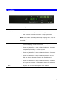
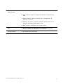
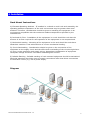
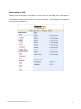
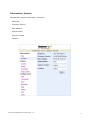
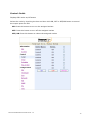
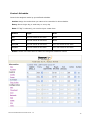
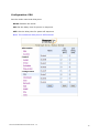
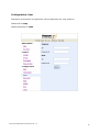
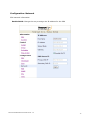
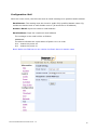
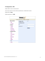
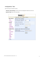
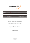
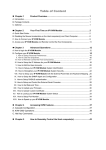
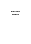
User Manual Per Port Monitoring Models Table of Contents 1. Introduction .............................................................................................................. 1 2. Package Contents ...................................................................................................... 2 3. Function ................................................................................................................... 3 4. Installation ............................................................................................................... 5 5. Web Interface ........................................................................................................... 6 1. Introduction The ServerLink Per Port Monitoring PDU is a network ready device designed and equipped with an Intelligent True RMS Current Meter to indicate the individual power consumption of each outlet or total PDU power consumption. The ServerLink PDU offers an easy to set up and user-friendly interface. The software enables you to remotely monitor power consumption of a single PDU or multiple PDUs. Features: Built-in web server allowing real time monitoring of each individual outlet or total PDU current consumption Built-in True RMS current meter Easy Setup. The meter can display the IP address of the PDU Homepage supports SSL Provides audible alarm when the power consumption exceeds the warning threshold or overload threshold Send email and traps when the power consumption exceeds the warning threshold or overload threshold Utility software can monitor a large amount of ServerLink PDUs at the same time Supports SNMP and provides MIB for the PDU to be monitored by NMS Indicates outlet and circuit status with LED Supports power on sequence Supports user-defined delayed time for power on and power off Scheduled control of outlet power User-defined group outlet control Auto reboots locked devices by pinging their IP address Supports network time protocols Optional probes can support temperature and humidity monitoring Provides power protection via the circuit breaker ServerLink PPM PDU User Manual Ver. 1.0 1 2. Package Contents The standard ServerLink PDU package contains a Power Distribution Unit with supporting hardware and software. Power Distribution Unit Rack Mount Brackets CD-ROM containing: ServerLink PDU User Manual ServerLink PDU Utility User Manual ServerLink PDU Utility Software MIB: Management Information Base for Network (ServerLink.mib) Adobe Acrobat Reader ServerLink PPM PDU User Manual Ver. 1.0 2 3. Function Functions Description Ethernet The Network connection for the built-in web server Audible Alarm PDU exceeds warning threshold - 1 beep per second PDU exceeds overload threshold - 3 beeps per second Note: The audible alarm will not change beeping status until the current drops more than 0.5A below the warning or overload threshold Function Button Press and release to turn off the warning beep. The overload beeping cannot be cancelled Press and hold, after 1 beep, release the button. The meter will display the current information and temperature/humidity in outlet sequence Press and hold, after 2 beeps release the button. The meter will display the IP address of the PDU Press and hold, after 4 beeps release the button and the PDU will change the way to assign the IP address…via DHCP or Fixed IP Press and hold, after 6 beeps release the button. The PDU will reset the power to all outlets and restore all settings to factory default Meter Displays the current consumption or IP Address ID Indicates the outlet number for the meter display ServerLink PPM PDU User Manual Ver. 1.0 3 LED Indicator SSL (Yellow): Light on means web access is protected by SSL DHCP (Green): Light on means PDU is assigned an IP address via DHCP Outlet 1-8 (Green): Light on indicates outlet power is on. Light off indicates outlet power is off Status (Red): Indicates each circuit status ENV RJ11 connector for optional environmental monitoring probe to monitor temperature and humidity Circuit Breaker Overload power protection ServerLink PPM PDU User Manual Ver. 1.0 4 4. Installation Rack Mount Instructions A) Elevated Operating Ambient - If installed in a closed or multi-unit rack assembly, the operating ambient temperature of the rack environment may be greater than room ambient. Therefore, consideration should be given to installing the equipment in an environment compatible with the maximum ambient temperature specified by the manufacturer. B) Reduced Air Flow - Installation of the equipment in a rack should be such that the amount of air flow required for safe operation of the equipment is not compromised. C) Mechanical Loading - Mounting of the equipment in the rack should be such that a hazardous condition is not achieved due to uneven mechanical loading. D) Circuit Overloading - Consideration should be given to the connection of the equipment to the supply circuit and the effect that overloading of the circuits might have on over current protection and supply wiring. Appropriate consideration of equipment nameplate ratings should be used when addressing this concern. E) Reliable Earthing - Reliable earthing of rack-mounted equipment should be maintained. Particular attention should be given to supply connections other than direct connections to the branch circuit (e.g. use of power strips). Diagram ServerLink PPM PDU User Manual Ver. 1.0 5 Hardware 1. Install mounting brackets 2. The ServerLink PDU comes with brackets for mounting in a rack. To mount the PDU into a rack, perform the following procedure 3. Attach the mounting brackets to the unit, using the four retaining screws provided for each of the brackets 4. Choose a location for the brackets. 5. Align the mounting holes of brackets with the notched hole on the vertical rail and attach with the retaining screws 6. Connect input and output power 7. Connect Ethernet cable to the PDU 8. Switch on the PDU Note 1: The default setting to assign the IP address is DHCP. If the PDU cannot get the IP from a DHCP server, the IP address will default to 192.168.0.216 ServerLink PPM PDU User Manual Ver. 1.0 6 5. Web Interface Login: Enter the ServerLink PDU IP address into a web browser Default User Name is snmp Default Password is 1234 ServerLink PPM PDU User Manual Ver. 1.0 7 Information: PDU Displays individual power consumption of each outlet or total PDU power consumption If an optional environmental probe has been connected, it will display the temperature and humidity information ServerLink PPM PDU User Manual Ver. 1.0 8 Information: System Displays PDU system information, including: Model No. Firmware Version MAC Address System Name System Contact Location ServerLink PPM PDU User Manual Ver. 1.0 9 Control: Outlet Displays PDU outlet on/off status Select the outlet by checking the box and then click ON, OFF or OFF/ON button to control the output power for PDU ON: Press this button to turn on the assigned outlets OFF: Press this button to turn off the assigned outlets OFF/ON: Press this button to reboot the assigned outlets ServerLink PPM PDU User Manual Ver. 1.0 10 Control: Group Control outlet power for multiple outlets Setting: Press the setting button to enter setting mode Outlet: Assign the outlet in a group Note: The outlet number needs to be input in alphabetical order ON: Press this button to turn on the assigned group OFF: Press this button to turn off the assigned group Active: Select this check box to enable the group to be controlled ServerLink PPM PDU User Manual Ver. 1.0 11 Control: Schedule Control the assigned outlet by pre-defined schedule Outlet: Assign the outlet that you want to be controlled in this schedule Every: Set a single day, a week day or every day Date: If “Sgl” is selected, you need to input a date here Action: Begin: End: ON Turn on outlet at this time None OFF Turn off outlet at this time None OFF/ON Turn off outlet at this time Turn on outlet at this time ON/OFF Turn on outlet at this time Turn off outlet at this time Active: Select this check box to enable the assigned scheduled control ServerLink PPM PDU User Manual Ver. 1.0 12 Control: Ping Action Automatically reboots locked devices by pinging their IP address Ping IP Address: Set the device IP address that you want monitored Response 10 minutes: The PDU will ping the assigned IP address once every minute. If the device does not respond, the number will be increased by one. After 10 attempts (10 minutes), if the device has not responded, the number will display 10 and the PDU will carry out the assigned action automatically Action: Select outlet action to “OFF” or “OFF/ON” Active: Select this check box to enable this Ping function ServerLink PPM PDU User Manual Ver. 1.0 13 Configuration: PDU Set the outlet name and delay time Name: Rename the outlet ON: Set the delay time for power on sequence OFF: Set the delay time for power off sequence Note: The maximum delay time is 255 seconds ServerLink PPM PDU User Manual Ver. 1.0 14 Configuration: Threshold Set the warning and overload threshold for each outlet Set the lower and upper threshold for temperature and humidity ServerLink PPM PDU User Manual Ver. 1.0 15 Configuration: User Change ID (Username) and password. ID and password are case sensitive Default ID is snmp Default password is 1234 ServerLink PPM PDU User Manual Ver. 1.0 16 Configuration: Network PDU network information Enable DHCP: Change the way to assign the IP address for the PDU ServerLink PPM PDU User Manual Ver. 1.0 17 Configuration: Mail When an event occurs, the PDU can send an email message to a specified email address Email Server: This setting must be a local or public fully qualified domain name. Eg. mailserver.domain.local or mail.domain.com.au (It cannot be an IP address) Sender’s Email: Input the sender’s email address Email Address: Input the recipient’s email address The message in the email will be as follows: XXXXXXXX The above indicates the outlet status of ports A to H in order X=0 : means the power off X=1 : means the power on Note: Make sure DNS server can resolve the Email Server’s domain name ServerLink PPM PDU User Manual Ver. 1.0 18 Configuration: SNMP When an event occurs, the PDU can send out a trap message to a specified IP address Trap Notification: Set receiver IP address for trap Community: Set SNMP community Read Community is public and fixed Default Write Community is “public” and can be modified by user ServerLink PPM PDU User Manual Ver. 1.0 19 Configuration: SSL Enable SSL for web communication User must input the correct ID and password to enable SSL function Default ID is snmp Default password is 1234 ServerLink PPM PDU User Manual Ver. 1.0 20 Configuration: Time Set the time for schedule control. Internet Time Setting: Get time from the assigned network time server. System Time: Input time manually. ServerLink PPM PDU User Manual Ver. 1.0 21