1
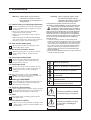
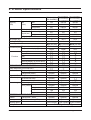
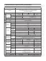
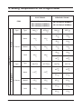
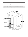
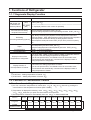
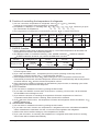
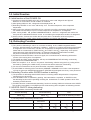
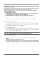
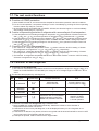
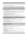
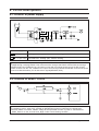
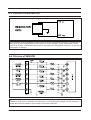
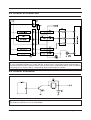
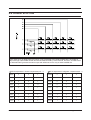
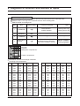
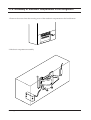
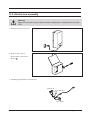
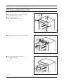
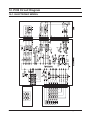
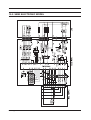
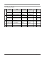
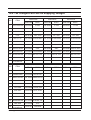
FREEZER/REFRIGERATOR
Model : SRL3928B(A)/39WEB(A)
SRL3926B(A)/39NEB(A)
SRL3916B(A)/39NMB(A)
SRL3626B(A)/36NEB(A)
SRL3616B(A)/36NMB(A)
GREEN
FREEZER / REFRIGERATOR
CONTENTS
1. Precautions .................................................. 2
2. Product Specifications ................................ 3
3. Electrical part specifications & standards............ 4
4. Setting Temperature of the Fridge/Freezer ............. 5
5. Circuit Diagram ............................................ 6
6. Functions & Operating Instruction............. 9
7. Functions of Refrigerator.......................... 13
8. Circuit Descriptions................................... 19
9. Diagnosis of disorder and method of repair ......... 24
10. Parts List.................................................... 31
11. Disassembly & Assembly ................................. 39
12. PCB Circuit Diagram ......................................... 45
1. Precautions
Warning : Please abide by the following
precautions in order to conduct
the maintenance procedures in a
safety fashion.
1-1. Caution when you replacing compressor.
• Do not smoke. Remove all the possible ignition
sources and then replace compressor in wellaired places.
• Don’t use welding machines if R600a
refrigerant does not exposed.
• In the case of gas leakage, always open the
windows.
• When cutting the SUCTION, DISCHARGE
pipe of the compressor, always take caution of
the inner pressure of the remaining gas.
1-2. Take out the power plug
• Always take out the power plug from the
outlet when doing repairs.
1-3. Be careful of electric shocks
• When inspecting the circuit, don’t touch the
battery charger and be careful of electric
shocks.
Cleaning : After completing repairs, clean
the surrounding area and the
refrigerator and tell the consumer
about the repairs being made.
This appliance contains a small amount of the
refrigerant isobutane(R600a), a natural gas with high
environmental compatibility but which is also
combustible. When transporting and installing
the appliance, care should be taken to ensure
that no parts of the refrigerating circuit are damaged.
Refrigerant squirting out of the pipes could ignite or
cause an eye injury. If damage occurs nevertheless,
avoid any flames or potential sources of ignition, and
air the room in which the appliance is standing for
several minutes.
• In order to avoid the creation of a flammable gas-air
mixture if a leak in the refrigerating circuit occurs, the size
of the room in which the appliance may be sited depends
upon the amount of refrigerant used. The room must be
1m3 in size for every 8 g of refrigerant R600a inside the
appliance. The amount of refrigerant contained in your
particular appliance is shown on the identification plate
inside the appliance.
• Never start up an appliance showing any signs damage. If
in doubt, consult your dealer.
1-4. Use proper components
• Always use the component labeled in the
service component chart when replacing
components for repairs.
Refers to prohibition.
1-5. Use proper tools
• Always use proper tools for repairs. If worn
out tools are used, it would cause defects in
tuning and electrical contact, leading to
accidents.
1-6. When doing repairs, inspect the POWER
CORD or whether there is fire in the lead wire
and make sure they are replaced.
1-7. Cutting of LEAD-WIRE
• For connecting the lead-wire that has been cut
off, use soldering or connector and always
disconnect the vinyl tapes.
Refers to prohibition of dismantling.
Refers to prohibition of contact.
Refers to guidelines which have to
be followed.
Refers to detaching the power plug
from the outlet.
Refers to earth connection for
preventing electric shocks.
1-8. Check for disconnection
• After completing the assembly, always measure
the disconnection resistance level, and turn on
the power after checking it is above 1MΩ.
1-9. Earth
• Check the status of earthing and repair the
incomplete ones.
Refers to possibility of death
or serious injury of a person.
Warning
1-10. Be careful of children
• There is always the possibility of danger when
doing repairs so make sure that children can’t
come nearby.
Samsung Electronics
Caution
Refers to possibility of injury
of a person or damage to
property.
2
2. Product Specifications
Model
SR-L3928B(A)
SR-L39WEB(A)
SR-L3926B(A)
SR-L39NEB(A)
SR-L3626B(A)
SR-L36NEB(A)
SR-L3916B(A)
SR-L39NMB(A)
SR-L3616B(A)
SR-L36NMB(A)
Capacity
Net
Total
345
350/325
350/325
(ISO)
(Liter)
Freezer
104
104/104
104/104
Refrigerator
241
246/221
246/221
595
595
595
Recessed type
631
631
631
Bar type
663
663
663
1920
1920/1820
1920/1820
76
76/73
76/73
No-frost
No-frost
No-frost
Dimension
Width(mm)
Depth(mm)
Height(mm)
Net weight (kg)
Cooling technology
Freezer performance
(4-STAR)
(4-STAR)
(4-STAR)
Temperature control type
Electronic
Electronic
Semi electronic
Temperature display type
Digital
Digital
LED
Optional
Optional
Optional
Transparent plastic
Vegetable/Salad bin(Moisture controller)
Optional
Optional
Optional
2
2
2
Interior lamp
Incandescent lamp
Optional
Optional
Fluorescent lamp
Optional
Optional
Can-carry
Optional
Optional
Optional
Door pocket Transparent/White
Dairy pocket
Optional
Optional
Optional
1EA
1EA
1EA
Deep bottle storage
1EA
1EA
1EA
Egg tray
1EA
1EA
1EA
Control&Display
Power off
Super Freezer
Function
VAC
ECO
Alarming display for power failure
Alarming melody for door open
REFRIGERATOR COMPARTMENT
Water dispenser(4.2L/Child lock)
Shelf
Door storage
Tempered glass shelf
FREEZER COMPARTMENT
Drawer
Transparent / White
Optional
Optional
Optional
Ice tray
Twist / Normal tray(2EA)
Optional
Optional
Optional
Blowing agent
Refrigerant
3
Cyclo Pentane Cyclo Pentane Cyclo Pentane
R600a(65g) / R134a(155g)
Samsung Electronics
3. Electrical part specification & standard
STANDARDS
SR-L3928B(A)/L39WEB(A), SR-L3926B(A)/L39NMB(A)
SR-L3916B(A)/L39NMB(A), SR-L3626B(A)/L36NEB(A)
SR-L3616B(A)/L36NMB(A)
ITEM
Model
Refrigeration cycle
Power source
Model
Compressor
230-240V/50Hz
DK4A1Q-L1U
(R600a)
230V/50Hz
220V/50Hz
127V/60Hz
DK172Q-L2U
DK172P-L2U
(R134a)
(R134a)
R.S.C.R
FREOL 15c/265cc
Split fin.Tube Type
starting type
Oil charging SUNISO-2GSD/265cc
Evaporator
Condenser
Natural Convection Type
Dryer
Molecular Sieve XH-9
I.D 0.75 L4,000mm
Capilary tube
Freezer
Sensor
502AT
Refrigerator
502AT
Defrost
502AT
Room TEMP.
502AT
310W/240V
2W/240V
Defrost
Lamp
310W/220V
2W/220V
For Only Fluorescent Lamp
7W/220V
Heater
Disc-Duct
7W/240V
Suct-Duct
15W/240V
15W/220V
15W/127V
Cover-EVAP,RE
7W/240V
7W/220V
7W/127V
Defrost
Electrical parts
Fuse
Defrosting
Defrost Time
Capacity
Protector
PTC-Relay
Running
Model
7W/127V
250V/10A, 72 4
6 19hr(Vary According To The Environmental Conditions)
4hr 10min(At The First Operating Cycle)
7min 2min
Rest Time
Over-Load
310W/127V
2W/127V
350VAC/3.5
350VAC/5
4TM213PHBYY-53
4TM232SHBYY-53
250VAC/12
4TM435PHBYY -53
On Temp
69
69
69
Off Temp
125
135
125
Model
J531Q35E330M385-2
33
Resistance
J531Q33E100M200-2
20%
10
20%
OSLAM DELUX S/E11W(Fluorescent Lamp)
Lamp
Refrigerator
Damper(Ge-
Freezer
ared)-motor
Door Switch
Motor Fan
Samsung Electronics
Freezer
KE257024025(240V/25W)
(130V/25W)
(Incandescent Lamp)
(Incandescent Lamp)
220 240VAC, 50/60Hz
110VAC, 50/60Hz
MN71MNBA6(M2LA49Z)
JX71MLBA6
H3005CL, 250VAC/25W
IS3210-SNL5C
IS3210SNF7F
IS3210SNP6C
4
4. Setting Temperature of the Fridge/Freezer
ELECTRONIC
ITEM
SR-L3928B(A)/L39WEB(A)
SR-L3926B(A)/L39NEB(A)
SR-L3626B(A)/L36NEB(A)
Type
Type
Freezer
Warm
F-Sensor
Normal
Temperature
Cold
Type
Type
Refrigerator
Warm
F-Sensor
Normal
Cold
5
ON(
-14
-18
-22
ON(
6.5
4.5
1.5
)
OFF( )
SEMI-ELECTRONIC
SR-L3916B(A)/L39NMB(A)
SR-L3616B(A)/L36NMB(A)
ON( )
OFF(
-14
-20
-15
-21
-17
-23
-20
-26
-22
-28
)
-20
-24
-28
OFF(
ON( )
OFF(
6.5
5.5
5.5
4.5
4.5
3.5
3.5
2.5
2.5
1.5
)
5.5
3.5
0.5
Samsung Electronics
5. Circuit Diagram
5-1. ELECTRONIC MODEL(SR-L3928B(A)/L39WEB(A)/
SR-L3926B(A)/L39NEB(A)) for Fluorescent Lamp Option
DA68-00476A
Samsung Electronics
6
5-2. ELECTRONIC MODEL (SR-L3928B(A)/L39WEB(A)/L3926B(A)/L39NEB(A)/
SR-L3626B(A)/L36NEB(A)) for Incandescent Lamp Option
DA68-00476C
7
Samsung Electronics
5-3. SEMI-ELECTRONIC MODEL (SR-L3916B(A)/L39NMB(A)/
SR-L3916B(A)/L36NMB(A))
DA68-00476E
Samsung Electronics
8
6. Function & Operating Instruction
6-1. Product Dimension
9
MODEL
A
B
C
D
HANDLE
SR-L3928B/L39WEB
SR-L3926B/L39NEB
SR-L3626B/L36NEB
SR-L3916B/L39NMB
SR-L3616B/L36NMB
SR-L3928A/L39WEA
SR-L3926A/L39NEA
SR-L3626A/L36NEA
SR-L3916A/L39NMA
SR-L3616A/L36NMA
1,920
1,920
1,820
1,920
1,820
1,920
1,920
1,820
1,920
1,820
1114.5
1114.5
1014.5
1114.5
1014.5
1114.5
1114.5
1014.5
1114.5
1014.5
1,169
1,169
1,169
1,169
1,169
1,169
1,169
1,169
1,169
1,169
631
631
631
631
631
663
663
663
663
663
RECESS
RECESS
RECESS
RECESS
RECESS
BAR
BAR
BAR
BAR
BAR
Remarks
“Y” “Z”
“Y”
“Y”
“Y”
“Y”
“Y” “Z”
“X”
“X”
“X”
“X”
ELECTRONIC
SEMI
ELECTRONIC
ELECTRONIC
SEMI
ELECTRONIC
Samsung Electronics
6-2. Part Name & Disassembly
• Tray disassembly
Take out food stuffs and
pull it out by following
the arrow.
Pull it out by following
the arrow.
Take out the water
bottle with the bottom
latch pressed.
• Ice compartment
Samsung Electronics
• Vegetable/Salad
compartment
• Freezer compartment
10
6-3. Circulation of Refrigerant
Compressor Back cluster pipe Cluster pipe Hot pipe Dryer
Evaporator Accumulator Suction pipe Compressor
11
Capillary tube
Samsung Electronics
6-4. Cool Air Circulation
Samsung Electronics
12
7. Functions of Refrigerator
7-1. 7-Segments Display Function
Section
Function
Initial POWER Notch setting Blink setting temperature of freezer until temperature reaches below
(YES)
TFSET_ON +3
ON (Power s/w,
instantaneous
Notch setting
-- displayed (until the notch control is operated)
electricity failure)
(NO)
Stabilization of the temperature in
the freezer (Since the setting
temperature have reached)
Blink if temperature goes above TFSET_ON +3 .
Display the setting temperature if the temperature goes below TFSET_ON +2
Display Blinking continuously ignoring temperature of freezer if displayed state of freezer before
defrosting
was Blinking . Display Setting temperature of freezer continuously ignoring temperature of
Defrosting
freezer
if
displayed
state of freezer before defrosting was Setting temperature of freezer .
(precooling+defrosting+pause)
Maintain temperature constantly while it reaches TFSET_OFF point When you return to the operating
cycle.
Blink if temperature goes above TFSET_ON +3
Display the setting temperature if the temperature goes below TFSET_ON +2
Super
Display “
Display “
Forced freezing
Forced defrosting
”(Forced Freezing)
”(Forced Defrosting)
Display function of the
temperature of refrigerator
If you push “REF. TEMP.” button indicative LAMP of refrigerator starts to
light up and blink the setting temperature of refrigerator.
If you do not input the KEY, it is blinked 5 times for 5 seconds at 0.5second interval and automatically converted to the displayed state of
setting temperature of refrigerator.
Display function of
the temperature of freezer
If you push “FRE. TEMP.” button indicative LAMP of freezer starts to light
up and blink the setting temperature of freezer.
If you do not input the KEY, it is blinked 5 times for 5 seconds at 0.5second interval and automatically converted to the displayed state of
setting temperature of freezer.
References
1) TFSET-ON : “Setting temperature of freezer +3 ”
2) TFSET-OFF : “Setting temperature of freezer -3 ”
7-2. Function of Thermostatic Control
A. Function of controlling the temperature of freezer
1) You can control the temperature of freezer from -17
to -25 at 1 interval by pushing the
control button of the temperature of freezer.(FRE. TEMP.)
2) Temperature is displayed in following order -19
-20
-21
-22
-23
-24
-25
-17
-18
whenever you push the control button of temperature.
3) The temperature of freezer is automatically set to be -19
on initial POWER ON.
Section
7 Segment
Controlled
temperature of freezer
13
Power 1 time push 2 time push 3 time push 4 time push 5 time push 6 time push 7 time push 8 time push 9 time push
–19˚C
–20˚C
–21˚C
–22˚C
–23˚C
–24˚C
–25˚C
–17˚C
–18˚C
–19˚C
–20˚C
–21˚C
–22˚C
–23˚C
–24˚C
–25˚C
–17˚C
–18˚C
Samsung Electronics
B. Function of controlling the temperature of refrigerator
1) You can control the temperature of refrigerator from 6
to 1
at 1 interval by
pushing the control button of the temperature of refrigerator.
2) Temperature is displayed in following order 4
3
2
1
6
5
whenever you push
the control button of temperature.
3) The temperature of refrigerator is automatically set to be 4
on initial POWER ON.
Section
power on
1 time push
2 time push
3 time push
4 time push
5 time push
6 time push
7 Segment
4˚C
3˚C
2˚C
1˚C
6˚C
5˚C
Controlled
temperature of freezer
4˚C
3˚C
2˚C
1˚C
6˚C
5˚C
note
C. SUPER Function
1) Press “SUPER” button briefly so that the LED lights up. The Freezer temperature will decrease and
the appliance will switch to the lowest temperature.
2) The displayed state is circulated in following order, SUPER is selected
SUPER is selected, whenever you push the SUPER button one time.
Initial power on
Section
Dispaly change
“SUPER”
Lamp off
1 time push
“SUPER”
Lamp ON
SUPER is released
2 time push
note
“SUPER”
Lamp off
3) If you select the ECO function while SUPER function is working, SUPER function is released and ECO
function begins to work.
4) If you select SUPER function, Compressor(and Fan) will be operating continuosly until the
temperature of freezer reaches -25 . (10 seconds after selection)
after working for 2 hours, compressor will be turned off
automatically for 25minutes, and then compressor will be turned on antomatically until the temperature
of freezer reaches -25
and this function will repeat for 8 hours.
6) If the commencing condition of defrosting is reached during super function, a defrosting cycle will be
postponed until the next 25minutes delay time.
5) If the temperature does not reach -25
D. ECO Function
1) You can select or release this function by pushing the ECO button.
2) If you select the SUPER function while ECO function is working, ECO function will be released
and SUPER function will begin to work.
3) If you select the function of controlling the temperature of freezer compartment or fresh food
compartment while ECO function is working, ECO function will be released.
4) If you select the ECO function, the temperature of freezer and refrigerator will be controlled as -17
and 6
, respectively.
E. VACATION Function
1) You can select or release this function by pushing the VAC button.
2) If you select the VAC function, the temperature of refrigerator will not be controlled and DAMPER
will be maintained as closed state. So that, cool air will not be supplied to the refrigerator.
3) VAC function does not affect setting up of the temperature of freezer.
4) If you push the button of controlling the temperature of refrigerator while VAC function is working,
VAC function will be released automatically.
Samsung Electronics
14
7-3. Initial Function
A. Initial function of first POWER ON
1) If power is pressed (POWER S/W ON), it will begin to make a self diagnosis and light all
DISPLAY for 2 seconds if normal condition is confirmed
2) After lighting DISPLAY ON, 7-Segment will be displayed as -- .
3) Defrosting HEATER is set to be ON forcibly for 3 seconds irrespective of the evaporator
temperature.
4) After turning the defrosting HEATER ON for 3 seconds, turn off the defrosting HEATER and
turn COMP. ON and keep it up for 5 minute irrespective of temperature of refrigerator.
5) After turning COMP. ON, operate DAMPER-MOTOR for control of refrigerator and confirm the
zero point and 60Hz/50Hz and then control as considering the temperature condition of refrigerator.
6) At this moment, if it does not confirm the zero point due to the disorder of the some part of
DAMPER-MOTOR, COMP. will be stoped immediately and display self diagnosis.
7-4. Defrosting Function
A. Common function
1) The period of defrosting is set to be 19 hours according to the COMP intergrated criterion.
Previous standard means the following conditions : frequency of opening and closing of the DOOR
of refrigerator must be less than one time, the temperature of refrigerator and the temperature of
freezer did not increase above TRSET ON+6 and TFSET ON+4 , respectively and special
functional button (VAC,SUPER,ECO)was not selected. Besides the predescribed condition,
the period of defrosting will be 6 hours and 50 minutes unconditionally.
2) If power is turned off and then is turned on again, the commencement of defrosting will be after
4 hours of the running time of compressor.
3) The COMP and FAN during defrosting, will stop and DAMPER-MOTOR will swing continuously.
4) At a pause time, DAMPER-MOTOR.
5) With the exception of 19 hours in the period of defrosting, will also swing the Pre_Cooling will be
executed by operating the COMP forcibly for 50 minutes before execution of defrosting.
6) You are recommended to have a pause time after completion of HEATING.
7) The HEATING for defrosting will be controlled by SENSOR. If SENSOR is out of order or the temperature
of EVAP is higher than HEATER ON temperature, HEATING will be skipped and ref only has a pause time.
B. Defrosting Function while SUPER function is working
1) The operation of defrosting while SUPER function is working will be delayed until the compressor
running time is to be 2 hours.
2) If the SUPER function is released by pushing the button before completion of SUPER function,
the defrosting function will be operating including the worked time of COMP. operation which was
worked by SUPER function.
3) If SUPER function is selected while defrosting function is working, DISPLAY will be set to be SUPER
ON condition immediately, but SUPER function will be working after completion of defrosting function.
C. HEATER ON/OFF during defrosting
1) The temperature of defrosting HEATER ON
General defrosting
Forced defrosting
below -5
Note
Same under all defrosting condition
below -5
2) The temperature of defrosting HEATER OFF
Section
15
6 hours and
50 minutes
19 hours
4 hours
OFF
12
12
12
OFF
12
12
12
Note
Samsung Electronics
7-5. TEST Function
TEST function is for examination of product and PCB, process control and service.
After confirmation of function of product by selecting TEST S/W, You must reboot the POWER and
operate self-diagnosis function.
A. Forced operating function
1) If you push REF. TEMP. and FRE. TEMP. button simultaneously for 5 seconds, COMP will begin to
work immediately and
will be displayed on the 7 SEGMENTS.
2) If the forced operation is selected, COMP. will work immediately without the delay of 5
minute. At this time, despite of running of defrosting the defrosting will stop.
3) If the forced operation is selected, COMP. will be working as PULL DOWN for 28 hours but the
temperature of refrigerator will be controlled by REF. TEMP. button.
4) During the forced operation, SUPER function does not work. If you select the SUPER function,
SUPER LAMP will be turned off immediately within 0.2 second after turning on the LAMP.
B. Forced defrosting function
1) If you push REF. TEMP. and FRE. TEMP. button simultaneously for 5 seconds only once during the
will be displayed on the 7 SEGMENTS.
forced defrosting, COMP will begin to set to be OFF and
during the forced defrosting, heating will not
work and will begin to work as delay time immediately.
2) If the temperature of evaporator sensor is below -5
C. TEST release function
1) If you push REF. TEMP. and FRE. TEMP. button simultaneously for 5 seconds only once during the
forced defrosting, the forced TEST function will be converted immediately to the previous temperature
setting state immediately and
will disappear on the DISPLAY.
7-6. The compensating function for electricity failure
A. NOTCH SAVE function
1) Whenever you push one of the SUPER, ECO, VAC, FRE.TEMP. and REF.TEMP. Button, the
current state will be saved and set to be the NOTCH and DISPLAY state which value was
memorized
as the one at rebooting point of POWER, respectively.
2) If the evaporator temperature at the inititial POWER ON state is less than the general defrosting
OFF temperature, a clause1) will begin to work. If the evaporator temperature at the inititial POWER
ON state is above the defrosting OFF temperature, the NOTCH of FRE.TEMP. and REF.TEMP.
will be set to be -19 and 4 , and SUPER, ECO and VAC function does not selected.
Samsung Electronics
16
7-7. The rest control functions
A. Function of COMP protection
1) After COMP is turned off, 5 minutes must be elapsed for the another operation under all conditions.
2) For the forced operation, compressor will begin to work immediately by pushing the forced operating
function without any delay for 5 minutes.
3) At the initial moment of POWER ON or POWER S/W ON, this function begins to work immediately
after heating of defrosting for 3 seconds.
B. Function of supercooling protection of refrigerator with a surrounding air of low temperature.
1) If the temperature of surrounding air begins to drop below 13 , the hysteresis of freezer sensor will
alter 3.0
into 1.5
and the temperature of refrigerator will be controlled with -1 shifted.
2) If the temperature of surrounding air will be between 14 and 31 , the hysteresis of freezer sensor
will be back to 3.0
and the refrigerator will be controlled with REF. TEMP. setting temperature.
3) If the temperature of surrounding air begins to rise above 33 , the hysteresis of freezer sensor will
alter 3.0
into 1.5 .
C. Function of NOTCH compensation
1) The NOTCH of refrigerator temperature will be -1
shifted when the NOTCH setting of freezer
and refrigerator are ranged from -17 to -19 and 1 to 2 , respectively.
2) The NOTCH of refrigerator temperature will be +2 shifted when the NOTCH setting of freezer
and refrigerator are ranged from -25 to -23 and 5 to 6 , respectively.
3) The NOTCH of refrigerator temperature will be set to be normal condition when the NOTCH setting
of freezer is ranged from -20 to -22 .
7-8. Function of Self diagnosis
A. Function of self diagnosis
1) The criterion of disorder of temperature sensor is out of temperature range from -50
to +50 . It is
treated as SHORT/OPEN if the MICOM input voltage is out of voltage range from 0.5 VOLT to 4.5
VOLT.
The disorder table prepared by self-diagnosis
NO
Items
1
R-SENSOR
2
F-EVAP
SENSOR
3
F-SENSOR
4
DAMPER-MOTOR
(GEARED)
Segments display
Contents of disorder
OPEN disorder
SHORT disorder
CONTROL RELAY of DAMPERMOTOR disorder or MOTOR,
REED S/W, MAGNET disorder
Note
if sensing below -50
if sensing above +50
cannot sensing
ON/OFF of REED
S/W for more than
1 minute operation
B. Function of initial self diagnosis by POWER ON
1) After POWER ON, inside of MICOM automatically detects the existence of the disorder of
temperature sensor within one second.
2) If bad sensor is found out by self diagnosis, it will be displayed rotatory on the 7 Segment at 0.5
second interval.
3) If bad sensor is detected, any button will not be recognized and all electrical load will be set to be OFF
and normal control of temperature will be reserved.
4) If bad part is repaired, it will be restored to the original state.
17
Samsung Electronics
C. Function of self diagnosis during normal operation
1) If you push SUPER and VAC button simultaneously for 5 seconds while the refrigerator is
working, “ ” on the 7 SEGMENTS will be displayed and function of self diagnosis will be selected.
2) KEY input will not work while self diagnosis function is operating. (except for POWER button)
7-9. Function of DOOR OPEN WARNING and control the light in refrigerator.
A. Warning of DOOR OPEN
1) BUZZER WARNING(ding-dong) SOUND will be generated if 2 minutes are elapsed continuously with
the refrigerator door open.
2) Initial BUZZER WARNING will be generated for 10 seconds after 2 minutes of DOOR OPEN, and
since then Ding-Dong sound will be generated every one minute for 10 seconds periodically.
3) If the refrigerator door is closed, warning will stop immediately.
4) If 10 minutes are elapsed continuously with the door open, light in refrigerator will be turned off and
warning continues to work.
B. Function of controlling the light in refrigerator
1) If 10 minutes are elapsed continuously with refrigerator door open, the light in the
refrigerator will be turned off automatically.
2) Despite of turning the light in the refrigerator off, it will be set to be ON again if you open the DOOR
which was closed.
3) At this moment, OFF time of the light will be set to be 10 minutes again.
7-10. Function of POWER ON/OFF & Alarm of electricity failure
A. Function of POWER ON/OFF
1) This function is selected or released by POWER button.
2) If the power switch is turned on, all electrical load work normally, -- will be displayed on the
7-SEGMENTS DISPLAY.
3) At above state, 7-SEGMENTS will display the setting temperature if you push the freezer or the
refrigerator setting BUTTON.
B. Function of Alarm of electricity failure
1) Above state( 1-3 of (A)) will be maintained if the power is turned on after electricity failure
2) -- on the 7-SEGMENTS means the occurrence of electricity failure if any handling of operating part
was not done specially.
7-11. Function of BUZZER
A. Button input
1) If you push the BUTTON during normal working condition, ding-dong sound will be generated
every 1 second.
2) Only ding sound is generated when the BUTTON is pushed continuously.
3) It does not sound in case of mistaken operation
B. Door alarm
1) DOOR OPEN ALARM will be generated as ding-dong, ding-dong if 2 minutes are elapsed
continuously with the refrigerator door open.
C. Forced operation
1) BEEP SOUND will be generated with a period of 0.25 second ON/0.75 second OFF if you push REF.
TEMP. and FRE. TEMP. button simultaneously for 5 seconds.
D. Forced defrosting
1) BEEP SOUND will be generated with a period of 0.1 second ON/1 second OFF if you push REF.
TEMP. and FRE. TEMP. button simultaneously for 5 seconds only once during the forced defrosting.
Samsung Electronics
18
8. Circuit Descriptions
8-1. Division of power supply
Used circuit
Power supply
Vcc (DC 5V)
Auxiliary power supply of MICOM and sensing part of SENSOR
Vcc (DC 12V)
LED DISPLAY working part, RELAY working
AC inputed power is decompressed through DC-TRANS and the reduced volatage is converted to the DC
voltage through rectifying DIODE. Then it becomes flat through 1000 F/35V CAPACITOR and through
REGULATOR 7812, stabilized DC 12V output comes and it is used as power source for RELAY and
DISPLAY.Also from this 12V, stabilized 5V output comes through REGULATOR7805 and used as power
source for MICOM auxiliary circuit and various signals(SENSOR, S/W).
8-2. Division of RESET Circuit
Division of RESET circuit makes it possible that programed function of system is set to be initial state
by initializing various parts such as RAM in MICOM when power is impressed or instantaneous
electricity failure is occurred. RESET voltage at the impressed moment of power is maintained as
LOW state for a few seconds and High under normal working condition.
19
Samsung Electronics
8-3. Division of RESONATOR
The role of this circuit is generation of synchronous CLOCK for transmission/reception of informations of
the logical elements inside MICOM and the basic time for the calculation of time. Rated parts must be
used in the division of RESONATOR because the calculation time of MICOM is changed or cannot work if
specification is changed.
8-4. Division of SENSOR
SENSOR and F-rated resistance are connected to the GROUND and DC 5V, respectively. The
resistance value which is changed by the temperature is converted to the voltage, and then respective
temperature is discriminated by input voltage to A/D PORT of MICOM
Samsung Electronics
20
8-5. Division of OPERATING
If at MICOM PORT begins to output High signal which corresponds to electrical load which we intend
to work, DRIVER IC(KA2657) is turned ON and at this moment, corresponding electrical load starts to
operate because the DC12 yield the electric current which flows corresponding RELAY COIL and RELAY
contacting point is set to be ON so corresponding electrical load begins to operate.
8-6. Division of BUZZER
TRANSISTOR begins to operate by CLOCK which was generated at MICOM and BUZZER sound is
generated by impression of 12V to the BUZZER.
21
Samsung Electronics
8-7. Division of DISPLAY, KEY SCAN
from MICOM #3-#7 GHID signal is generated for 10 sec with the period of 2 sec HIGH signal and for the
lighting the corresponding LED, the CONTROL terminal of MICOM PIN #8-#11 output the output signal
which is coincident with GRID signal. Meanwhile by pushing the KEY which is connected by respective
GRID, corresponding signal is inputted to MICOM.
Samsung Electronics
22
8-8. Division of OPTION
The output such as GRID wave form which is only generated at the initial POWER ON is accepted as
input through SWITCHING DIODE and discriminate OPTION by matrix method. #23, #24, and #25 PORT
of MICOM PORT generate the same output with GRID wave form only at initial POWER ON.
Shift of temperature in freezer compartment(unit : ˚C)
Shift of temperature in refrigerator compartment(unit : ˚C)
SHIFT
3
2
1
SHIFT
6
5
4
Default
0
0
0
Default
0
0
0
-1.0˚C
0
0
1
-1.0˚C
0
0
1
-2.0˚C
0
1
0
-2.0˚C
0
1
0
-3.0˚C
0
1
1
-3.0˚C
0
1
1
+1.0˚C
1
0
0
+1.0˚C
1
0
0
+2.0˚C
1
0
1
+2.0˚C
1
0
1
+3.0˚C
1
1
0
+3.0˚C
1
1
0
+4.0˚C
1
1
1
+4.0˚C
1
1
1
23
Samsung Electronics
9. Diagnosis of disorder and method of repair
Method of inspecting MAIN-PCB
At the self diagnosis CHECK, you have to turn the main power OFF and turn it ON and check.
ERROR CODE of self diagnosis is prepared as shown in the following table.
ERROR CODE of self diagnosis
NO
Items
Segments display
1
R-SENSOR
2
F-EVAP
SENSOR
3
F-SENSOR
4
DAMPER-MOTOR
(GEARED)
Contents of disorder
Note
OPEN disorder
SHORT disorder
if sensing below -50
if sensing above +50
CONTROL RELAY of DAMPERMOTOR disorder or MOTOR,
REED S/W, MAGNET disorder
cannot sensing
ON/OFF of REED
S/W for more than
1 minute operation
Door s/w
R-sensor
Refrigerator compartment
Freezer compartment
Resistance of sensor and voltage of MICOM
according to the temperature
temperature resistance voltage temperature resistance voltage
-35
-34
-33
-32
-31
-30
-29
-28
-27
-26
-25
-24
-23
-22
-21
-20
-19
-18
-17
-16
68150
64710
61480
58430
55550
52840
50230
47770
45450
43260
41190
39240
37390
35650
33990
32430
30920
29500
28140
26870
4.360
4.331
4.301
4.269
4.237
4.204
4.170
4.134
4.098
4.061
4.023
3.985
3.945
3.905
3.863
3.822
3.778
3.734
3.689
3.644
Samsung Electronics
-15
-14
-13
-12
-11
-10
-9
-8
-7
-6
-5
-4
-3
-2
-1
0
1
2
3
4
25650
24510
23420
22390
21410
20408
19580
18730
17920
17160
16430
15740
15080
14450
13860
13290
12740
12220
11720
11250
3.597
3.551
3.504
3.456
3.408
3.360
3.310
3.260
3.209
3.159
3.108
3.057
3.006
2.955
2.904
2.853
2.801
2.750
2.698
2.647
temperature resistance voltage temperature resistance voltage
5
6
7
8
9
10
11
123
13
14
15
16
17
18
19
20
21
22
23
24
10800
10370
9959
9569
9195
9839
8494
8166
7852
7552
7266
6992
6731
6481
6242
6013
5792
5581
5379
5185
2.596
2.545
2.495
2.445
2.395
2.346
2.296
2.248
2.199
2.151
2.104
2.057
2.012
1.966
1.922
1.873
1.834
1.791
1.749
1.707
25
26
27
28
29
30
31
32
33
34
35
36
37
38
39
40
41
42
43
44
5000
4821
4650
4487
4329
4179
4033
3894
3760
3631
3508
3390
3276
3167
3026
2962
2864
2770
2680
2593
1.667
1.626
1.587
1.549
1.511
1.474
1.437
1.401
1.366
1.332
1.298
1.266
1.234
1.203
1.172
1.143
1.113
1.085
1.057
1.030
24
Preliminary examination
1. Check out whether power of an outlet flows out or not, and POWER CODE is connected
normally or not before repair of disorder
2. Check out whether POWER S/W on the PANEL PCB is pushed or not.
3. If additional disorder may detected, check out by referencing the note of next page.
9-1. When the POWER does not transmitted
25
Samsung Electronics
9-2. When the disorder has detected by self diagnosis
A. When the Disorder of F-ROOM SENSOR has occurred
B. When the disorder of F-EVA SENSOR has occurred
Samsung Electronics
26
C. When the disorder of R-ROOM SENSOR has occurred
D. When the disorder of DAMPER REED S/W has occurred
27
Samsung Electronics
E. When the disorder of DOOR S/W has occurred
Samsung Electronics
28
9-3. When BUZZER sounds is generated continuouly
References
DOOR OPEN WARNING of refrigerator compartment alarms for 10 seconds after 2 minutes when DOOR opened
initially. If the door is opened continuously it is alarmed for 10 seconds with a period of 10 seconds.
Because the penetration of moisture or vapor into DOOR S/W causes the junction SHORT of DOOR S/W, the
warning is alarmed continuously by judgement of MICOM which regards the DOOR as open state.In this case,
DOOR is regarded as continuously opened state after 10 minutes and the lamp of refrigerator is set to be OFF. So
if you open the DOOR, the lamp of refrigerator is maintained as OFF state.
If the moisture or vapor penetrates into the junction and corrodes it, the lamp of refrigerator is kept as OFF state and
DOOR OPEN warning does not work because the signal does not inputted to the MICOM.
A. When Ding-Dong sound is generated continuously.
B. When the beeper sound is generated continuously
29
Samsung Electronics
C. When the KEY of PANEL-PCB has not been selected.
Samsung Electronics
30
10. Parts List
10-1. Freezer Compartment
31
Samsung Electronics
■
Freezer List
NO
CODE-NO
1
1-1
1-2
1-3
1-4
2
3
DA66-00087A
DA71-00108A
DA66-00071A
DA64-00158A
DA61-20136A
DA66-00086A
DA66-00091A
DA66-00091B
DA66-00092A
DA66-00092B
DA66-00101A
DA66-00056A
DA67-00302A
DA61-00137A
DA61-00082A
DA66-00052A
DA66-00053A
6002-000215
6002-000213
DA96-00015A
DA96-00015B
DA96-00024A
DA32-10105Q
DA47-10162F
DA60-00053A
DA60-00054A
DA63-00395E
DA63-00395F
6002-000215
DA63-00396R
DA63-00396S
DA97-00150A
DA63-00237A
DA61-00081A
DA63-40119A
DA31-00002P
DA31-00002U
DA31-00002X
DA61-00117A
DA31-10107C
DA31-10107B
DA31-00019A
DA34-10125B
6002-000467
DA31-00026A
DA63-00359A
DA66-00095A
DA61-20128A
6002-000215
DA32-10109P
6006-001083
DA47-00056A
DA47-00056B
DA47-00056C
6002-000215
DA66-00052A
DA66-00053A
DA67-40146B
4
5
5-1
5-2
6
6-1
6-2
6-3
6-4
6-5
7
7-1
7-2
7-3
7-4
8
8-1
9
9-1
9-2
9-3
9-4
9-5
9-6
9-7
9-8
9-9
9-10
9-11
9-12
9-13
9-14
9-15
9-16
9-17
10
11
12
13
Samsung Electronics
ITEM
TRAY ICE-ASSY
FIXER-TRAY ICE
TRAY-ICE
KNOB-TRAY ICE
SPRING-ICE MAKER
TRAY FRE-C-ASSY
TRAY FRE-A-ASSY
TRAY FRE-A-ASSY
TRAY FRE-B-ASSY
TRAY FRE-B-ASSY
TRAY-ICE,CUBE, ASSY
TRAY-ICE,CUBE
CAP-TRAY-ICE,CLUB
SUPPORT-RAIL ASSY
SUPT-RAIL
ROLLER-FRE-A
ROLLER-FRE-B
SCREW-TAPPING
SCREW-TAPPING
EVAP ASSY
EVAP ASSY
EVAP ASSY
SENSOR ASSY
THERMO FUSE
SPACER-EVAP,L
SPACER-EVAP,I
COVER-EVAP FRONT-ASSY
COVER-EVAP FRONT-ASSY
SCREW-TAPPING
COVER EVAP REAR-ASSY
COVER EVAP REAR-ASSY
COVER EVAP REAR-ASSY
COVER-EVAP REAR
CASE-MOTOR
GROMMET-MOTOR
MOTOR-FAN
MOTOR-FAN
MOTOR-FAN
CASE-G-MOTOR
MOTOR-GEARD
MOTOR-GEARD
FAN-PROPELLER
SWITCH SENSITIVE
SCREW
BLADE
GASKET-BLADE
SHAFT-BLADE ASSY
SPRING-FAN
SCREW-TAPPING
SENSOR-ASS’Y
SCREW ASSY TAPP
HEATER-EVAP COVER,RE
HEATER-EVAP COVER,RE
HEATER-EVAP COVER,RE
SCREW-TAPPING
ROLLER-FRE-A
ROLLER-FRE-B
TRAY ICE
SPECIFICATION
HIPS,SRL36,L39
HIPS,W9540,SRL36,L39
SRL36,L39,W9540
HIPS,W9540,SRL36,L39
STS304,ID1.0,PI10.5,SR-53E
SRL36,L39
WHT
TRANSE PARENT
WHT
TRANSE PARENT
SRL36,L39
SRL36,L39
HIPS,WHT,SRL36,L39
HIPS,SRL36,L39,WHT
POM,SRL36,L39
POM,SRL36,L39
TH-1S,M4XL16,ZPC(YEL),MSWR1
TH,M4,L12,ZPC(YEL),SWRCH18
SRL36,L39,FIN,A1100P-H24,240V,310W
SRL36,L39,FIN,A1100P-H24,220V,310W
SRL36,L39,FIN,A1100P-H24,127V,310W
502AT,COMBI-PJT,300,YELLOW,F-DEF-SENSOR
250V,10A,72
127V EVAP ASSY
127V EVAP ASSY
TWIST,PP
NORMAL,PP
TH,1,M4.0,L16,ZPC(YEL),MSWR1
240V/50Hz
220v/50,60Hz
127V/60Hz
PP,NTR,SRL36,L39,T1.5
PP,SRL36,L39,NTR
NBR,BLK
240V/50Hz, 2550 rpm
220V/50Hz, 2550 rpm
127V/60Hz, 2550 rpm
PP,SRL36,L39,NTR
M2LA49Z,220V,SR-41~518
M2BC59ZR12,110V
SRL36,L39,NTR
5V,Black
PH-2S 4X10 YEL
PC,NTR,SRL36,L39
SILICON
POM,SRL36,L39
STS27,ID1.0
TH,1,M4.0,L16,ZPC(YEL),MSWR1
502AT
TH,M4,L16,ZPC(YEL),SWRCH18
240V
220V
127V
TH,1,M4.0,L16,ZPC(YEL),MSWR1
POM
POM
PE, NTR, SR-1500
Q’TY
REMARK
1
1
2
2
2
1
2
1
1
1
1
1
1
1
1
1
1
2
1
1
1
1
1
1
1
1
1
4
1
1
1
1
1
2
1
1
1
1
1
1
1
1
2
1
1
1
1
2
1
1
1
1
1
6
6
6
2
32
10-2. Refrigerator Compartment
33
Samsung Electronics
■
Refrigerator List
NO
CODE-NO
ITEM
1
1-1
1-2
2
2-1
2-2
2-3
2-4
3
3-1
3-2
3-3
4
4-1
4-2
4-3
5
5-1
5-2
5-3
6
6-1
DA61-00126B
DA69-00102B
DA67-00203A
DA67-00272A
DA64-00119A
DA66-00061A
DA67-20346K
DA64-00116A
DA67-00268A
DA64-00114A
DA64-00115A
DA67-20346J
DA67-00270A
DA64-00115A
DA64-00116A
DA67-20346J
DA67-00269A
DA64-00114A
DA64-00116A
DA67-20346H
4713-001041
4713-001140
4713-001141
DA63-00235A
6002-000213
DA97-00228A
DA63-00239B
DA72-00170A
DA67-30266D
6002-000215
DA63-10467A
DA32-10105B
DA63-00234A
DA63-00870A
DA63-00245B
DA64-00118A
DA64-00117A
DA63-00371A
DA63-00390A
DA70-00138A
DA41-00014A
DA41-00018B
DA41-00013A
DA41-20160B
DA39-00112A
6002-000213
DA34-00015C
6001-000366
DA97-00526A
DA63-00328B
DA64-00180B
DA64-00180A
DA63-00375A
DA63-00375A
DA70-00208A
DA41-00043A
DA41-00042A
DA67-00329A
DA67-00444A
DA67-00206A
DA67-00207A
BOX-VEG ASS,Y
BOX-VEG
CAP-VEG
SHELF-VEG ASSY
TRIM-SHELF-FRONT, LOW
LEVER-HUMIDITY
SHELF GALSS
TRIM-SHELF REAR-A
SHELF REF-B-ASSY
TRIM-SHELF REF-FRONT
TRIM-SHELF REAR-B
SHELF GALSS
SHELF REF-C-ASSY
TRIM-SHELF REAR-B
TRIM-SHELF REAR-A
SHELF GALSS
SHELF REF-A-ASSY
TRIM-SHELF REF-FRONT
TRIM-SHELF REAR-A
SHELF GALSS
LAMP-FLUORESCENT
LAMP-INCANDESENT
LAMP-INCANDESENT
COVER-LAMP REF
SCREW-TAPPING
COVER DAMPER-REF ASSY
COVER-DAMPER REF
SPACER-DAMPER, REF
CAP-SCREW
SCREW-TAPPING
COVER-SENSOR
SENSOR-ASSY
COVER-SUCTION, REF
COVER-TOP TABEL ASSY
COVER-TOP TABLE ASSY
BUTTON-PCB, R
BUTTON-PCB, L
GASKET-BUTTON PCB,R
GASKET-BUTTON PCB,L
PLATE-EARTH
PBA-PANEL
PBA-MAIN
PBA-SUB
PBA-SUB
WIRE HARNESS-INVERTER
SCREW-TAPPING
SWITCH-DOOR
SCREW-MACHING
COVER TOP TABLE,ASSY
COVER TOP TABLE
BUTTON PCB,R
BUTTON PCB,L
GASKET-BUTTON PCB,R
GASKET-BUTTON PCB,L
PLATE-EARTH
PAN-PCB
MAIN-PCB
COVER DISPLAY
GASKET-WINDOW
SHELF-REF LOW
SHELF-REF
7
8
9
9-1
9-2
10
11
12
13
14
15
15-1
15-2
15-3
15-4
15-5
15-6
15-7
15-8
15-9
15-10
15-11
15-12
16
17
17-1
17-2
17-3
17-4
17-5
17-6
17-7
17-8
17-9
17-10
18
19
Samsung Electronics
SPECIFICATION
GPPS
HIPS
GLESS
PP,W9540
PP,WHT
GLASS,T4
P.P,BJ-730T4
GLASS,,T4
P.P,BJ-730T4
PP,W9540
GLASS,T4
GLESS
P.P,W9540
P.P,BJ-730T4
GLASS,T4
GLESS
P.P,BJ-730T4
P.P,BJ-730T4
GLASS,T4
220V,150mA,11W
240V,25W
130V,25W
PP
TH-1S,M4X12,ZPC(YEL)
PP,W-9540
PP,W-9540
PS
PP
TH-1S,M4X12,ZPC(YEL)
HIPS
502AT
PP,W9540
HIPS,SC-97527R
ABS,SC-97527R,IN HOUSE
ABS,SC-97527R
ABS,SC-97527R
MBR
MBR
SBHG1
COMBI
COMBI
240V
127V
INVERTER
TH-1S,M4X12,ZPC(YEL)
H3005CL,250V,25W
FH,M4X10,CR PLT,STS304
SEMI
≥≠ø¨ ABS
ABS,SC-97527R
ABS,SC-97527R
NBR,BLACK
NBR,BLACK
COMBI
COMBI
COMBI
GPPS
NBR
GPPS(HF-2660),NTR
GPPS(HF-2660),NTR,SRL36,L39
Q’TY
REMARK
2
2
2
1
1
2
1
1
1
1
1
1
1
1
1
1
3
3
3
3
1
1
1
1
1
1
1
1
1
1
1
1
1
1
1
1
1
1
1
1
1
1
1
1
1
2
1
2
1
1
1
1
1
1
1
1
1
1
1
1
4
34
10-3. Door
35
Samsung Electronics
■
Door List
NO
1
2
3
3-1
4
5
5-1
5-2
6
6-1
7
8
9
9-1
9-2
9-3
10
11
12
13
13-1
13-2
13-3
13-4
13-5
14
15
16
17
18
CODE-NO
DA91-00711A
DA91-00711B
DA91-00694A
DA91-00694C
DA91-00697A
DA91-00694B
DA91-00694D
DA91-00697B
DA91-00699A
DA91-00699B
DA91-00699C
DA91-00701A
DA91-00701B
DA63-00228A
DA63-00228B
DA71-00118A
DA63-00227A
DA63-00227B
DA63-00405A
DA63-00405B
DA63-00229A
DA63-00229B
DA63-00230A
DA63-00263A
DA63-00263B
DA71-00119A
DA66-00058A
DA63-00380A
DA64-00157A
DA67-00216A
6001-000715
DA67-00298A
DA61-00083A
DA66-00073D
DA63-00247A
DA74-00054A
DA67-30216A
DA63-00240A
DA65-20004A
DA74-00051A
DA61-00139A
DA67-00194A
DA66-00054A
DA66-00055A
DA63-00376A
DA71-20155B
Samsung Electronics
ITEM
ASSY DOOR FOAM REF, DISP
ASSY DOOR FOAM REF, DISP
ASSY DOOR FOAM REF
ASSY DOOR FOAM REF
ASSY DOOR FOAM REF
ASSY DOOR FOAM REF
ASSY DOOR FOAM REF
ASSY DOOR FOAM REF
ASSY DOOR FIANM FEF
ASSY DOOR FIANM FEF
ASSY DOOR FIANM FEF
ASSY DOOR FIANM FEF
ASSY DOOR FIANM FEF
GUARD-BOTTLE
GUARD-BOTTLE
GUARD-BOTTLE
GUARD-VARIETY
GUARD-VARIETY
GUARD-DAIRY ASSY
GUARD-DAIRY ASSY
GUARD-DAIRY
GUARD-DAIRY
COVER-DAIRY
GUARD-BOTTLE-DISP
GUARD-BOTTLE-DISP
GUARD-BOTTLE-B
TRAY-EGG
GUARD-CAN CARRY
HANDLE BAR(FAT)
CAP-HANDLE
SCREW-MACHINE
CAP HOLE HANDLE BAR
HINGE-WASHER,LOW
SHAFT-WASHER,D
GROMMET-HINGE
TANK WATER-ASSY
CAP-COVER WATER
COVER-WATER TANK
CLAMP-TANK
TANK WATER
CASE-COCK ASSY
CAP-HINGE HOLE
TRAY-DISPENSER-A
TRAY-DISPENSER-B
COVER DISPENSER-ASSY
FIXER-CASE,ASSY
SPECIFICATION
SRL39, RICH-ROUND, COOLN’COOL
SRL39, RICH-ROUND, COOLTECH DY
SRL39, RICH-ROUND, COOL N’ COOL
SRL39, RICH-ROUND, COOLATRVH DY
SRL39, RICH-ROUND, BAR-HANDLZ
SRL39, RICH-ROUND, COOOOLATRVH DY
SRL39, RICH-ROUND, COOLTECH DY
SRL39, RICH-ROUND, BAR-HAUDLZ
SRL36,39, RICH-ROUND, RECZSS
SRL36,39, RICH-ROUND, RECZSS
SRL36,39, RICH-ROUND, RECZSS
SRL36,39, RICH-ROUND, BAR-HANDLZ
SRL36,39, RICH-ROUND, BAR-HANDLZ
GPPS(HF-2660),SD-97527R,SRL36,L39,WHT
GPPS(HF-2660),TRANSPARENT
MSWR10,SNC2,SRL36,L39,PI5.5
REF,GPPS,SC-97527R,SRL36,L39,WHT
REF,GPPS,TRANSPARENT
REF,GPPS,SC-97527R,SRL36,L39,WHT
REF,GPPS,TRANSPARENT
REF,GPPS,SC-97527R,SRL36,L39,WHT
REF,GPPS,TRANSPARENT
GPPS,SRL36,L39
GPPS,W9540,SRL39,WHT
GPPS,TRANSPARENT
MSWR10,SNC2,SRL39(D),PI5.5
SRL36,L39,S.S
ABS(HG-0760)
ABS(HG-0760S),W-97527R,SRL39
ABS(HG-0760),W-97527R,SRL39
TH,+,M5 L16,SWRCH18A
ABS(HG-0760S),WHT(SC-97527R)
POM(TP-20),NTR
T2.0,RD-PVC,N.T.R,SRL36,L39
NY-66,NTR,SRL36,L39,S.S
PP,SRL39
PE,WHT
PP,SRL39,S.S
P.C
PP,SRL39
ABS,SC-97527R,SRL39,DISP
PP,SC-97527R,WHT
ABS(HG-0760H),SRL39,W-97527,S.S,WHT
ABS(HG-0760H),SRL39,W-97527,S.S,WHT
SRL39
ABS,SR-L5285,L5785,SC-9343
Q’TY
REMARK
1
1
1
1
1
1
1
1
1
1
1
1
1
1
1
1
5
5
1
1
1
1
1
1
1
1
1
1
1
1
2
1
1
1
4
1
1
1
2
1
1
1
1
1
1
1
36
10-4. Cabinet Parts & Unit
37
Samsung Electronics
■
Cabinet Parts & Unit Lists
NO
1
2
3
4
5
6
7
8
9
10
11
12
12-1
13
14
15
16
17
17-1
17-2
17-3
18
19
20
21
22
23
24
25
26
27
28
29
30
31
32
33
34
CODE-NO
DA61-00075A
DA61-00073A
DA60-10123E
DA67-00196A
DA67-30218R
DA60-00003A
DA67-00195A
DA60-10123E
DA61-00146A
DA61-00128A
DA61-00127A
DA61-00084A
DA67-00197A
DA60-10124A
DA63-00241A
DA26-00003A
DA26-00003B
DA71-00109A
DA71-00101A
DA61-40115B
DA60-90124A
DA61-00089A
DA63-00398A
2501-001185
2501-001185
2501-001045
6002-001118
DA35-10013B
DA35-10013E
DA34-10003H
DA34-10003N
DA66-00031C
DA73-30102B
DA63-40004A
DK4A1Q-L1U
SK170H-L1U
DK172P-L2U
DA63-10352A
6002-000217
DA60-20008A
DA60-00018A
DA60-10124A
DA60-10107A
Samsung Electronics
ITEM
ASSY CABI FOAM
HINGE-UPPER-L
HINGE-UPPER ASSY-R
SCREW-TAP TITE
CAP-HINGE HOLE-UPP
CAP-SCREW
SCREW-TAP,PH
CAP-HINGE HOLE-MID
SCREW-TAP TITE
HINGE MID ASSY
HINGE-LOW-L-ASSY
HINGE-LOW,R-ASSY
FOOT-FRONT
CAP-HINGE HOLE-LOW
SCREW-TAP TITE
COVER-LEG,FR
TRANS DC
TRANS DC
CHASSIS-COMP ASSY
CHASSIS-COMP
CASTER-FRONT
RIVET
CASE-JUNCTION
COVER COMP-ASSY
POWER-CODE
C-OIL
C-OIL
C-OIL
SCREW-TAPPING
RELAY-PTC
RELAY-PTC
PROTECTOR-O/L
PROTECTOR-O/L
TRAY-DRAIN WATER
DRYER-ASSY
GROMMET-COMP
COMPRESSOR
COMPRESSOR
COMPRESSOR
COVER-RELAY
SCREW-TAPPING
BOLT-HEX
SCREW-ASSY
SCREW-TAP TITE
SCREW-EARTH
SPECIFICATION
Q’TY
SHP1,SRL36,L39,ZPC2
SHP1,SRL36,L39,ZPC2
HH,M6,L19,ZPC2-W,GSD 3KM
PP,SC-97527R,WHT
ABS,SC-97527
PH,TAPPING,4X10
PP,SC-97527R,WHT
HH,M6,L19,ZPC2-W,GSD 3KM
SRL36,L39
SHP1,SRL36,L39,ZPC2
SHP1,SRL36,L39,ZPC2
PP,NTR,SRL36,L39
PP,SC-97527R,WHT
HH,M6,L16,ZPC2-Y
SC-97527R
240V,50/60Hz
127V,50/60Hz
SBHG1
SBHG1
PP,NTR,SR-50
MSWR10,OD6.0,L56,ZPC3
PP,SRL36,L39,S.S,NTR
SBHG1,SRL39
3.5 ,350V
5 ,350V
12 ,250V
TH,SOCKET(HEX),M4
J531Q35E330M3852
J531Q33E100M2002
4TM213PHBYY-53
4TM412PHBYY-53
T3-P/J(2ND),S.S,0.6
CU,OD18.85,ID2,L102,2P,10.0G
NBR
R600a
R134a
R134a
BLK
TH,4X8,ZPC(YEL),MSWR10
SM30C,L42.6
TH+,STS304
HH,M6,L16,ZPC2-Y
BSBN PT M4X10
1
1
4
1
1
1
1
2
1
1
1
2
1
4
1
1
1
1
1
2
2
1
1
1
1
1
1
3
1
1
1
1
1
1
4
1
1
1
1
2
4
2
4
2
REMARK
OPTION
38
11. Disassembly & Assembly
11-1. Replacement of refrigerator Incandescent lamp
Warning
Always take out the power plug when replacing the refrigerator lamp. There is the
danger of electric shock.
1. Remove a screw from the cover and pull down the
cover with the back latch pressed.
2. Pull out the lamp.
3. After replacing the lamp, assemble the front latch of
cover and then connect the back latch and screw on the
cover.
11-2. Replacement of refrigerator fluorescent lamp
Warning
Always take out the power plug when replacing the refrigerator lamp. There is the
danger of electric shock.
1. Remove a screw from the cover and pull down the
cover with the back latch pressed.
2. Pull out the lamp.
3. After replacing the lamp, assemble the front latch of
cover and then connect the back latch and screw on the
cover.
39
Samsung Electronics
11-3. Disassembly of the cooling cycle unit in the freezer
1. Take out the case from the freezer.
2. Remove 2 screws from the holder of the cooling
cycle unit.
2 screws
3. Pull out the holder of the cooling cycle unit and
disconnect wire terminals.
4. Pull forward the insulating material of the cooling
cycle unit and remove the wire terminal and insulating
material.
5. Remove 2 screws securing refrigerator duct and
pull it out by following the arrow.
Samsung Electronics
40
6. Remove 3 screws from the back cover of the
cooling cycle unit and remove the latch with (+)
driver.
Remove 3 screws
7. Remove the latch of the cooling cycle unit cover
from the bottom.
■ Assembly of the cooling cycle unit in the freezer
41
Samsung Electronics
11-4. Assembly of mechanic compartment in the refrigerator
1. Remove the screws from the securing cover of the mechanic compartment at the back bottom.
2. Mechanic compartment assembly
Samsung Electronics
42
11-5. Electric box assembly
Warning
Make sure the power plug is taken out when replacing the components for the main
PCB.
1. Disconnect the power cord.
2. Remove the cover of
electrical box with insert
driver.( )
3. Assembly specification of electric box
TEST S/W
Condenser
D/C Trans
43
Samsung Electronics
11-6. Disassembly of Top Table
● With the door open, unscrew screws
with a screw driver(“+” type).
● Lever out top table
with a screw driver (“_” type).
● Repair or change electric parts of top table.
● Attach the top table and click into
hook
by pressing.
Samsung Electronics
44
12. PCB Circuit Diagram
12-1. ELECTRONIC MODEL
45
Samsung Electronics
12-2. SEMI ELECTRONIC MODEL
Samsung Electronics
46
12-3. Service Parts
NO
CODE-NO
ITEM
STANDARD
COMPANY
Q’ty
DA41-00018A
MAIN PCB
COMBI-P/J
Kwangju Electronics
1
DA41-00042A
MAIN PCB(SEMI)
COMBI-P/J
Kwangju Electronics
1
DA41-00042C
MAIN PCB(SEMI(AH/AM)) COMBI-P/J
Kwangju Electronics
1
DA41-00014A
PANEL PCB
COMBI-P/J
Seoul Semiconductor
1
DA41-00043A
PANEL PCB(SEMI)
COMBI-P/J
Seoul Semiconductor
1
3
DA32-10105B
R-SENSOR
502AT
Dong Kwang
1
4
DA32-10109P
F-SENSOR
502AT
Dong Kwang
1
5
DA32-10105Q
F DEF-SENSOR
502AT
Dong Kwang
1
6
DA26-00003A
DC-TRANS
COMBI-P/J
Sigma Telecom
1
7
DA41-00013A
SUB PCB
COMBI-P/J
YuYu
1
1
Remarks
2
47
INVERTER PCB
Samsung Electronics
12-4. The Changed Part Lists As Supplying Voltages
240V/50Hz
NO
1
2
3
230V/50Hz
220V/50Hz
ITEM
CODE-NO
SPEC.
CODE-NO
SPEC.
CODE-NO
SPEC.
THERAFLUOROETHANE DA02-00038A
R-600a
DA02-40030A
R-134a
DA02-40030A
R-134a
DK172Q-L2U
DA59-00158A
DK172Q-L2U
COMPRESSOR
DA59-00144A DK4A1Q-L1U DA59-00158A
PROTECTOR-O/L DA34-10003H 4TM213PHBYY-53 DA34-10003K 4TM232SHBYY-53 DA34-10003K 4TM232SHBYY-53
4
C-OIL
5
RELAY-PTC
DA35-10031B J531Q35E330M3852 DA35-10013B J531Q35E330M3852 DA35-10013B J531Q35E330M3852
6
DC-TRANS
DA26-00003A 240V/50, 60Hz DA26-00003A 240V/50, 60Hz DA26-00003A
240V/50, 60Hz
7
EVAP-ASSY
DA59-00118B 240V, 310W DA59-00118B 240V, 310W DA59-00118C
220V, 310W
8
8-1
2501-001185
COVER-EVAP RE ASSY DA63-00396A
MOTOR-FAN
3.5uF, 350V
240V
2501-001186
DA63-00396A
5uF, 350V
240V
2501-001186
5uF, 350V
DA63-00396B 220V/50, 60Hz
DA31-00002P 235V/50Hz/2550RPM DA31-00002P 235V/50Hz/2550RPM DA31-00002U 220V/50,60Hz/2550RPM
8-2 GEARD-MOTOR DA31-10107C M2LA49Z, 220V DA31-10107C M2LA49Z, 220V DA31-10107C M2LA49Z, 220V
9
PBA-SUE
DA41-00013A
240V
DA41-00013A
240V
DA41-00013A
240V
10
Lamp
Incandescent
4713-001140
240V/25W
4713-001140
240V/25W
4713-001140
240V/25W
NO
ITEM
CODE-NO
SPEC.
CODE-NO
SPEC.
127V/60Hz
CODE-NO
1
2
3
THERAFLUOROETHANE DA02-40030A
COMPRESSOR
DA59-00169A
SPEC.
R-134a
DK172P-L2U
PROTECTOR-O/L DA34-10004H 4TM435PHBYY-53
4
C-OIL
5
RELAY-PTC
DA35-10013N J531Q33E100M200-2
6
DC-TRANS
DA26-00003B 127V/50, 60Hz
7
EVAP-ASSY
DA59-00118E 127V, 310W
8
8-1
2501-001045
COVER-EVAP RE ASSY DA63-00396C
MOTOR-FAN
12uF, 250V
127V/60Hz
DA31-00002V 127V/60Hz/2550RPM
8-2 GEARD-MOTOR DA31-10107B JX71MLBA6, 110V
9
PBA-SUE
DA41-20160B
127V
10
Lamp
Incandescent
4713-001141
130V/25W
Samsung Electronics
48
MEMO
MEMO
ELECTRONICS
272, Oseon-Dong, Kwangsan-Gu,
Kwangju-City, Korea, 506-253
TEL : 82-62-950-6810, 6811
FAX : 82-62-950-6829
© Samsung Electronics Co., Ltd.
Refrigerator Division 2000. 02
Printed in Korea
Code No : DA68-00535A