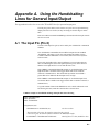
1
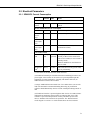
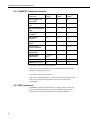
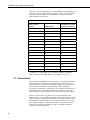
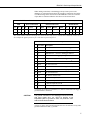
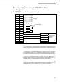
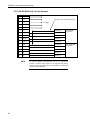
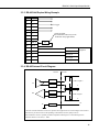
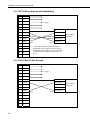
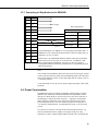
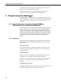
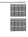
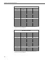
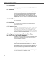
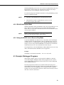
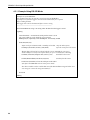
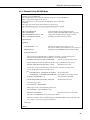
SDM-SIO1 Serial
Input/Output Module
3/08
C o p y r i g h t © 2 0 0 8
C a m p b e l l S c i e n t i f i c , I n c .
Warranty and Assistance
The SDM-SIO1 SERIAL INPUT/OUTPUT MODULE is warranted by
CAMPBELL SCIENTIFIC, INC. to be free from defects in materials and
workmanship under normal use and service for twelve (12) months from date
of shipment unless specified otherwise. Batteries have no warranty.
CAMPBELL SCIENTIFIC, INC.'s obligation under this warranty is limited to
repairing or replacing (at CAMPBELL SCIENTIFIC, INC.'s option) defective
products. The customer shall assume all costs of removing, reinstalling, and
shipping defective products to CAMPBELL SCIENTIFIC, INC. CAMPBELL
SCIENTIFIC, INC. will return such products by surface carrier prepaid. This
warranty shall not apply to any CAMPBELL SCIENTIFIC, INC. products
which have been subjected to modification, misuse, neglect, accidents of
nature, or shipping damage. This warranty is in lieu of all other warranties,
expressed or implied, including warranties of merchantability or fitness for a
particular purpose. CAMPBELL SCIENTIFIC, INC. is not liable for special,
indirect, incidental, or consequential damages.
Products may not be returned without prior authorization. The following
contact information is for US and International customers residing in countries
served by Campbell Scientific, Inc. directly. Affiliate companies handle
repairs for customers within their territories. Please visit
www.campbellsci.com to determine which Campbell Scientific company
serves your country. To obtain a Returned Materials Authorization (RMA),
contact CAMPBELL SCIENTIFIC, INC., phone (435) 753-2342. After an
applications engineer determines the nature of the problem, an RMA number
will be issued. Please write this number clearly on the outside of the shipping
container. CAMPBELL SCIENTIFIC's shipping address is:
CAMPBELL SCIENTIFIC, INC.
RMA#_____
815 West 1800 North
Logan, Utah 84321-1784
CAMPBELL SCIENTIFIC, INC. does not accept collect calls.
SDM-SIO1 Table of Contents
PDF viewers note: These page numbers refer to the printed version of this document. Use
the Adobe Acrobat® bookmarks tab for links to specific sections.
1. Introduction..................................................................1
2. Specifications ..............................................................2
2.1 Supported Data Rates and Protocols.........................................................2
2.2 Electrical Parameters ................................................................................3
2.2.1 SDM-SIO1 Current Consumption ..................................................3
2.2.2 SDM-SIO1 Voltage Specifications.................................................4
2.2.3 EMC Compliance............................................................................4
2.3 Temperature and Humidity Ranges ..........................................................5
2.4 Physical Parameters ..................................................................................5
2.5 Datalogger Compatibility .........................................................................5
3. Installation....................................................................5
3.1 Connections ..............................................................................................6
3.2 Safety Considerations ...............................................................................8
3.3 Examples for Connecting the SDM-SIO1 to Other Equipment................9
3.3.1 RS-485 One to One Connection Example ......................................9
3.3.2 RS-485 Multi Unit / In Line Example ..........................................10
3.3.3 RS-485 Half Duplex Wiring Example ..........................................11
3.3.4 RS-485 Internal Circuit Diagram..................................................11
3.3.5 RS-232 Wiring Example with Handshaking.................................12
3.3.6 RS-232 Basic 3-Wire Example .....................................................12
3.3.7 Connecting a 9-Way Socket to the SDM-SIO1 ............................13
3.4 Power Conservation................................................................................13
4. Programming the Datalogger ...................................14
4.1 Special Information about the Serial I/O CRBasic Commands when used
with the SDM-SIO1 .............................................................................14
4.1.1 SerialOpen ....................................................................................14
4.1.2 SerialClose ....................................................................................17
4.1.3 SerialIn..........................................................................................17
4.1.4 SerialOut .......................................................................................17
4.1.5 SerialInBlock ................................................................................17
4.1.6 SerialOutBlock..............................................................................18
4.1.7 SerialInChk ...................................................................................18
4.1.8 SerialInRecord ..............................................................................18
4.1.9 SerialFlush ....................................................................................18
4.1.10 Serial Input Errors.......................................................................18
4.2 Configuring Handshaking and Receive Only Modes .............................18
4.2.1 Using RTS/CTS and Automatic Handshaking..............................18
4.2.2 RS-485 Half-Duplex Mode...........................................................19
4.2.3 Using the RS-232 Link in Receive Only Mode ............................19
i
SDM-SIO1 Table of Contents
4.3 Example Datalogger Programs .............................................................. 19
4.3.1 Example Using RS-232 Mode...................................................... 20
4.3.2 Example Using RS-485 Mode...................................................... 21
5. Firmware Upgrades and Flash Signature Errors ....22
5.1 Upgrading the Firmware ........................................................................ 22
5.2 Firmware Signature Errors..................................................................... 22
Appendix
A. Using the Handshaking Lines for General
Input/Output .......................................................... A-1
A.1 The Input Pin (Pin 8)........................................................................... A-1
A.2 The Output Pin (Pin 9) ........................................................................ A-2
Tables
3-1. SDM Address Settings............................................................................ 6
3-2. SDM-SIO1 Connections (left to right as viewed from the front of
the unit) ............................................................................................... 7
3-3. SDM-SIO1 Functional Description of the Connections ......................... 7
4-1. Communications Port Parameters RS-232............................................ 15
4-3. Communications Port Parameters RS-485 Half Duplex....................... 16
4-4. Communications Port Parameters RS-232 Receive Only Mode .......... 16
ii
SDM-SIO1 Serial Input/Output Module
The SDM-SIO1 Module is designed to allow expansion of the number of serial ports
available on a datalogger for communicating with intelligent sensors or driving external
displays.
1. Introduction
The SDM-SIO1 Module connects to Campbell Scientific dataloggers using the
SDM port and communication protocol. It connects to the remote serial device
using industry standard hardware that can be set to RS-232, RS-485 or RS-422
signal levels. When operating in RS-232 mode it also supports hardware
handshaking. RS-422 mode is functionally the same as RS-485 mode except
the connection is limited to a point to point system. Connections and
programming for RS-422 are otherwise identical to RS-485.
The SDM-SIO1 will accept serial data and store it in its buffer which is 2047
bytes in size allowing remote equipment to transmit large amounts of data
without needing to stop other processes in the datalogger. Up to 15 SDM-SIO1
peripherals can be connected to a single logger using the SDM port, allowing
the user to connect 15 different items of equipment to their logger with ease, in
addition to any connections made to the datalogger’s other serial ports.
To start using the SDM-SIO1 it is first necessary to work out how data will be
exchanged with a sensor. In the case of a sensor there are basically two options,
either the datalogger requests data and then picks up the response, or the sensor
transmits data “one-way” using its own time base. The latter mode is more
common but can lead to problems with synchronizing the sensor measurements
with the logger program and can also lead to the occasional missing data value
as there are two independent clocks. Once the method of communication and
the communication standard is defined then refer to section 3 below to install
the module and connect it to the datalogger and the serial device.
The SDM-SIO1 Module is implemented in such a way that it looks like a builtin serial port to the user when writing programs in CRBasic. This means all the
user needs to do is define the address of the SDM-SIO1, using a rotary switch
on the side of the unit. The serial port can then be used as if it were built into
the datalogger. The only difference in operation between the SDM-SIO1 and a
built-in port is that there will be a small delay when transferring data to and
from the device via the SDM connection (see section 4.1).
The SDM-SIO1 can also be used in ‘talk-through’ mode to allow a user to talk,
via a terminal module, to a sensor connected to the SDM-SIO1 for test and
diagnostic purposes. Please refer to the logger manual for further details.
Section 4 of this manual gives the differences in the use of this module
compared to the datalogger standard serial ports, plus there are some simple
examples.
1
SDM-SIO1 Serial Input/Output Module
2. Specifications
2.1 Supported Data Rates and Protocols
Data rates and protocols are set up using the SerialOpen command in CRBasic.
The SerialOpen command is discussed elsewhere in this document.
Supported data rates
300, 1200, 2400, 4800, 9600, 19200, 38400, 57600, and 115200 bits/s
Supported modes of operation
RS-232 (Full duplex and receive only), RS-485 (Half and full duplex), RS- 422
(Half and full duplex). Hardware CTS/RTS flow control is supported in RS232 mode, the handshaking lines can also be used as general purpose I/O lines.
Supported data format
8, and 7 bit data size*
none, odd, or even parity
one or two stops bits. *
In 7 bit mode with no parity the user must insure that the characters received
by the SDM-SIO1 have a delay of at least one bit period or greater between
them. This does not affect any other configuration and does not affect
transmissions out of the SDM-SIO1.
Miscellaneous information
•
Auto baud rate detection is NOT supported
•
Use of the serial port for general PakBus communications is not currently
supported.
Buffer sizes
2
•
Transmit buffer size: 767 Bytes (Buffer from the logger to the sensor)
•
Receive buffer size: 2047 Bytes (Buffer from the sensor to the logger)
Both transmit and receive buffers are fill and discard type, i.e. once the
buffers become full no new information is accepted and all further data is
discarded until space is made when the logger requests data from the
SDM-SIO1.
SDM-SIO1 Serial Input/Output Module
2.2 Electrical Parameters
2.2.1 SDM-SIO1 Current Consumption
Nominal
Max
Notes
100 µA
Current after SerialClose has been
called.
General Currents
Standby
current
70 µA
RS-232 and RS-485 Current Consumption(1)
Idle current
5.5 mA
6 mA
After SerialOpen has been called
Idle current
(receive
only)
4.1 mA
4.5 mA
After SerialOpen in receive only mode
Active
current (RS232)
11.5 mA
12 mA
Active RS-232 command
Active
current (RS485)
12.5 mA
13 mA
Active RS-485 command (no
termination resistors)
3 mA
per load
Average expected increase in drawn
current per RS-232 line connected in
idle or active modes (no extra current in
stand-by mode).
Line Load Currents
RS-232 line
load
2 mA per
load
Both TX and RTS are considered to be
RS-232 loads.
RS-485 line
load(2)
40 mA(3)
77 mA(4)
This extra current is only present when
actively transmitting
(1) All currents are measured with no loads connected
(2) The RS-485 transmit pair is disabled when not transmitting in order to save
power higher value resistors can be used to save power dependent upon the
application. For many applications, especially with shorter cable runs, no
load/termination resistors will be needed.
(3) Single 100R load between transmit lines. Two 100R resistors (one on each
end) is the maximum recommended loading. Removing any termination
resistance should dramatically decrease current consumption during transfer of
data
(4) The RS-485 interface is protected against short circuits via a 44R resistance
making this the maximum current possible even during short circuit. This
resistance is part of the ESD protection circuitry and will be present at all
times; it shouldn’t affect normal circuit operations. The ‘RS-485 internal
circuit diagram’ in section 3.3.4 of this manual shows the circuit in detail.
3
SDM-SIO1 Serial Input/Output Module
2.2.2 SDM-SIO1 Voltage Specifications
Minimum
Voltage(1)
Nominal
Voltage(1)
Maximum
Voltage(1)
Power supply, +12 V
connection(2)
7V
12 V
20 V
RS-232 input threshold
Low
0.8 V
-
-
RS-232 input threshold
High
-
-
2.4 V
RS-232 input absolute
maximum(2)
-
±15 V
±18 V
RS-232 input
resistance
3 kΩ
5 kΩ
7 kΩ
RS-232 output voltage
swing(3)
±5 V
±5.4 V
-
RS-232 output
absolute maximum
-
-
±13.2 V
RS-485 input
(Differential)
200 mV(4)
-
6V
RS-485 output
(Differential)
2 V (at 50
Ohms)
-
-
SDM lines (high level)
4.3 V
5V
5.7 V
SDM lines (low level)
0V
-
0.7 V
Connection
(1) Values are volts D.C. (except resistances)
(2) It is NOT recommended that the user runs their SDM-SIO1 at maximum
ratings for extended periods of time
(3) Assuming a worst case 3 KΩ load
(4) It is not recommended that the user allows such low input voltages as there
will be an increased chance that external noise may cause errors in the
incoming data
2.2.3 EMC Compliance
The SDM-SIO1 has been tested and shown to comply with IEC 61326. The
device incorporates transient and surge protection that is designed to meet
IEC61000-4-5, level 4, providing the device is adequately grounded.
4
SDM-SIO1 Serial Input/Output Module
2.3 Temperature and Humidity Ranges
Temperature
Range
Minimum
Maximum
Standard range
-20ºC
+50ºC
Extended range
(optional)
-40ºC
+80ºC
(Contact Campbell Scientific
for further extended
temperature requirements)
Humidity
Minimum
Maximum
Notes
Standard range
0%
95%
(non-condensing)
Notes
2.4 Physical Parameters
Main body
Height: 2.2” H (5.4 H cm)
Width: 3.1” W (8.0 W cm)
Depth: 1.0” D (2.5 D cm)
Main body including base mounting flange
Height: 2.2” H (5.4 H cm)
Width: 4.5” W (11.2 W cm)
Depth: 1.0” D (2.5 D cm)
Weight: 2.8 oz. (80 g) (approximately)
Mounting centers are 10.2 cm (4”)
2.5 Datalogger Compatibility
The SDM-SIO1 is currently supported in operating systems of the CR800/850,
CR1000 and CR3000 dataloggers. Please contact Campbell Scientific for
details of support in the CR5000 and CR9000X, which may be made available
at a later date.
3. Installation
The SDM-SIO1 is normally mounted on the backplane of a Campbell
Scientific enclosure using the screws and plastic inserts provided. The SDMSIO1 is designed to be installed in a dry, non-condensing environment. Before
fixing it, select and set the SDM address as this requires access to the side of
the case. The SDM address is set with a screw driver. Below is a list of the
possible SDM addresses and their relationships to the COM port number in the
SerialOpen command.
5
SDM-SIO1 Serial Input/Output Module
There can be up to 15 SDM-SIO1s on a single SDM bus. Each SDM-SIO1 will
need to have a unique address before they are powered up. If other equipment
is present on the bus, whether it’s an SDM-SIO1 or not, the user needs to
insure no addresses are the same.
TABLE 3-1. SDM Address Settings
Rotary Switch
Position
SDM Address
SerialOpen Command
Comm. Port Number
0
0
32
1
1
33
2
2
34
3
3
35
4
4
36
5
5
37
6
6
38
7
7
39
8
8
40
9
9
41
A
10
42
B
11
43
C
12
44
D
13
45
E
14
F
(1)
15
46
(1)
47(1)
(1) Address ‘F’ is not available as it’s the broadcast address. Setting this
address will result in the SDM-SIO1 having an address of ‘0’ not ‘F’.
3.1 Connections
Connection to the SDM-SIO1 is achieved via the 15 terminals arranged along
the top of the unit. The terminals are spring loaded providing an easy and
reliable method of connection. Wires should be stripped .25” (7mm), twisted
and inserted in the round hole while opening the clamp by pushing a
screwdriver in the adjacent rectangular hole, or by pushing a screwdriver into
the hole on the side of the connector. Remove the screwdriver to close the
clamp making sure the clamp grips the wire rather than the plastic insulation.
If there is a need to insert more than one wire in a terminal when using
multistrand wire, twist the conductors together first. If using solid wires, either
solder or crimp wires together before insertion. For RS-485 connections note
that the RS-232 terminals double up as a secondary connection, so it is rare to
have multiple conductors in one terminal as both sets of connections can be
used either for forming an RS-485 daisy-chain or for adding termination
resistors at each end of a network.
6
SDM-SIO1 Serial Input/Output Module
When making connections to the datalogger always insure power to the
datalogger is switched off and connect the ground (G) connection first. Below
is a table showing all the connections on the SDM-SIO1. There are a number
of pins that are common within the unit. These are also shown below.
TABLE 3-2. SDM-SIO1 Connections (left to right as viewed from the front of the unit)
SDM
Power Connections
RS-232 Connections
RS-485/RS-422
C1
C2
C3
G
+12 V
G
RX-A
CTS-B
RTS-Y
TX-Z
0V
Z
Y
B
A
1
2
3
4
5
6
7
8
9
10
11
12
13
14
15
15
14
13
12
10
9
8
7
Note: Italic numbers indicate which pins are connected internally (for use with RS-485 termination resistors etc.).
For example the signals present on pin 7 will also be present on pin 15.
TABLE 3-3. SDM-SIO1 Functional Description of the Connections
Case Text
Description
1
C1
SDM data enable line – connect to datalogger SDM C1
2
C2
SDM clock line – connect to datalogger SDM C2
3
C3
SDM data line – connect to datalogger SDM C3
4
G
Connect to the datalogger power ground (G)(1)
5
+12 V
Main power supply – connect to logger 12 V
6
G
RS-232 0 V reference/second G connection(2)
7
RX-A
RS-232 receive line
8
CTS-B
RS-232 CTS hardware handshaking line / output
9
RTS-Y
RS-232 RTS hardware handshaking / input
10
TX-Z
RS-232 transmit line
11
0V
RS-485 0V reference line(3)
12
Z
‘-’ RS-485 output line, line Z
13
Y
‘+’ RS-485 output line, line Y
14
B
‘-’ RS-485 input line, line B
15
A
‘+’ RS-485 input line, line A
(1) At least one of the two G terminals (‘G’) must be connected to the logger’s
ground terminal or earth boss.
CAUTION
The ground connection to the datalogger should be made
with large gauge wire, e.g. 16/0.2 to provide a low
impedance path to ground to allow full protection from
static and electrical transients.
(2) The ‘G’ (pin 6) can be used for the RS-232 zero volt reference or any other
ground connection needed, e.g. shields.
7
SDM-SIO1 Serial Input/Output Module
(3) There is a 100R resistor in series with the datalogger’s ground connection.
This connection should be used when connecting RS-485 equipment by long
wire lengths. It insures both systems have a common ground reference point.
See section 3.2 below before connecting.
As shown above in Table 3-3 connections 1 to 5 need to be made to the
datalogger. SDM connections are made to appropriate logger control ports or to
the dedicated SDM port when fitted, e.g. the CR3000. The connection of the
wires to the remote serial device will vary with type of device and method of
communication. It is necessary to work out the best mode of operation of the
serial device, taking into consideration issues such as power consumption,
cable lengths (RS-485 being better than RS-232), synchronization of data
collection etc.
In section 3.3 there are some examples of different connection schemes for the
serial devices. Further discussion of different modes of operation is given in
section 4.
NOTE
Do not connect both RS-232 and RS-485 interfaces to the SDMSIO1 at the same time as this may cause a bus contention and
even possibly cause damage.
3.2 Safety Considerations
The SDM-SIO1 is considered to be a component of a measurement system that
is installed in an enclosure and wired up in accordance with this manual. Due
to space considerations full details of the maximum ratings of the connections
are not given on the device. Instead the user should study this manual and in
particular section 2.1.2 to determine the maximum voltages that are applicable
to any terminal before starting an installation.
The RS-485 0V ground reference connection may be needed to insure all units
are referenced to a common ground voltage. This is more often needed with
long cable runs. It is advisable to check the difference in ground potential with
some caution before connecting any wires, to insure the potential differences
are reasonably close and excessive current will not flow between the two
ground wires. There is a current limiting resistor fitted in the 0V line in the
SDM-SIO1, but this will not be adequate in the event of a serious ground fault,
e.g. the ground references being 120 V apart, due to faulty AC wiring. If a
large potential difference is found please seek the advice of a qualified
electrician before continuing with the installation.
8
SDM-SIO1 Serial Input/Output Module
3.3 Examples for Connecting the SDM-SIO1 to Other
Equipment
3.3.1 RS-485 One to One Connection Example
1
C1
2
C2
3
C3
4
G
5
+12V
6
G
7
RX-A
8
CTS-B
9
RTS-Y
10
TX-Z
11
0V
RS-485 0V
12
Z
RS-485_B
13
Y
RS-485_A
14
B
RS-485_Z
15
A
RS-485_Y
To logger
100 R or higher
R
R
RS-485
equipment with
termination
resistors
Notes:
• Z, Y, B and A are connected to their corresponding differential wire pairs
when in RS-485/RS-422 mode. Where A and Y are the ‘+’ lines and ‘B and Z
are the ‘-‘ lines.
• Connections 7-10 are connected internally to connections 12-15. This allows
for terminations resistors to be added when in RS-485 mode (if needed) or,
more than one connection to the I/O lines or TX and RX lines in RS-232 mode.
• If the use of termination resistors is required in RS-485 mode then they
should be connected between pins TX-Z and RTS-Y for the ZY line and CTSB and RX-A for the A B line (see diagrams elsewhere in document).
• In half duplex RS-485/RS-422 mode the Z Y and A B pairs are connected
internally by the hardware without the need for any user interaction. The user
should connect their wires to ZX and YS, as ‘A’ and ‘B’ are disabled.
9
SDM-SIO1 Serial Input/Output Module
3.3.2 RS-485 Multi Unit / In Line Example
1
C1
2
C2
3
C3
4
G
5
+12V
6
G
RS-485_0V
7
RX-A
RS-485_Y
8
CTS-B
RS-485_Z
9
RTS-Y
RS-485_A
10
TX-Z
RS-485_B
11
0V
RS-485 0V
12
Z
RS-485_B
13
Y
RS-485_A
14
B
RS-485_Z
15
A
RS-485_Y
NOTE
10
RS-485 0V for ground referencing
To logger
First RS-485
equipment
Second RS-485
equipment
As with all RS-485 configurations the use of termination
resistors is optional. They tend not to be required with shorter
cable runs and with modern slew-rate limited driver technology
(as used in the SDM-SIO1).
SDM-SIO1 Serial Input/Output Module
3.3.3 RS-485 Half Duplex Wiring Example
1
C1
2
C2
3
C3
4
G
5
+12V
6
G
7
RX-A
8
CTS-B
9
RTS-Y
10
TX-Z
11
0V
RS-485 0V
12
Z
RS-485_B
13
Y
RS-485_A
14
B
RS-485_Z
15
A
RS-485_Y
To logger
100 R or higher
(Termination resistor may not be
needed for many applications)
R
RS-485
equipment
3.3.4 RS-485 Internal Circuit Diagram
Internal
External
Z
22R
TX
R
22R
Y
B
22R
RX
22R
100R or higher*
R
100R or higher*
A
0V
100R
0V
* Note the external termination resistors are optional. Some applications can use much higher value resistors
and some may not need resistors at all depending on the distance and wire quality involved.
If the termination resistor is primarily needed for impedance matching then a value matching the line
resistance will have to be used, i.e. 100R.
11
SDM-SIO1 Serial Input/Output Module
3.3.5 RS-232 Wiring Example with Handshaking
1
C1
2
C2
3
C3
4
G
5
+12V
6
G
0V
7
RX-A
RS-232_RX
8
CTS-B
RS-232 RTS
9
RTS-Y
RS-232 CTS
10
TX-Z
11
0V
12
Z
13
Y
14
B
15
A
To logger
DTE
DCE
RS-232 DCE
equipment
RS-232 TX
* Note CTS and RTS are optional if hardware
handshaking is not required. Not connecting the
handshaking lines will decrease the overall current
consumption of the SDM-SIO1 and the RS-232
device.
3.3.6 RS-232 Basic 3-Wire Example
12
1
C1
2
C2
3
C3
4
G
5
+12V
6
G
0V
7
RX-A
RS-232_RX
8
CTS-B
9
RTS-Y
10
TX-Z
11
0V
12
Z
13
Y
14
B
15
A
To logger
DTE
DCE
RS-232 TX
RS-232 DCE
equipment
SDM-SIO1 Serial Input/Output Module
3.3.7 Connecting a 9-Way Socket to the SDM-SIO1
1
C1
2
C2
3
C3
4
G
5
+12V
6
G
0V
Pin 5
7
RX-A
RS-232_TX
Pin 3
8
CTS-B
RS-232 CTS
Pin 8
9
RTS-Y
RS-232 RTS
Pin 7
10
TX-Z
RS-232 RX
Pin 2
11
0V
12
Z
13
Y
14
B
15
A
To logger
DTE Configuration
RS-232 9-Way Dtype Connector
Note 2
1) Note this diagram is for adding a 9 way D-type plug to the SDM - SIO1. A
standard one to one serial lead can then be used to connect to another piece of
equipment (e.g. a PC or sensor)
2) Since there is no standard that indicates whether certain devices should be
DTE or DCE it may be necessary to reverse the CTS – B and RTS-Y pins
when wiring hardware handshaking. You may cross the wires either by
crossing them manually (as shown by dotted lines) or, by purchasing a special
cable for this purpose.
Notes:
• The CTS-B (CTS) and RTS-Y (RTS) lines can also be used to trigger external
circuitry if desired when not being used in handshaking mode. Note that when
using CTS-B and RTS-Y lines as input and output that the voltage levels are
+/-12V NOT 0 and 5V.
• CTS-B and RTS-Y can’t be used as separate input and outputs when in RS485 mode.
3.4 Power Conservation
The SDM-SIO1 features an industry standard RS-232/RS-485 driver chipset
(Maxim 3160) which insures maximum likelihood of compatibility with all
other devices. When the driver is powered on it uses more power than one of
the datalogger’s control port based “com ports” – typically 6 mA minimum,
partly because it generates the correct signal levels which in itself requires
power and partly because, in the case of RS-232 signals, the resting state of
~-6V driving a nominal RS-232 ~3k load implicitly wastes ~2 mA of current
per line.
To avoid excess current use, the chip can be turned off when not in use, e.g.
between polled measurements, simply by closing the serial port, using
Serialclose (see below). When running in RS-232 mode with a sensor that only
13
SDM-SIO1 Serial Input/Output Module
sends data one-way to the datalogger, run the SDM-SIO1 in “receive only
mode” as this does not turn on the output drivers.
If using RS-232 mode avoid connecting handshaking lines that are not
required. This eliminates 2 mA drain per line for unused lines.
4. Programming the Datalogger
The normal Serial port instructions such as SerialOpen and SerialIn are used
with the SDM-SIO1. A program written for a standard serial port will usually
work with the SDM-SIO1, as long as the timing of the measurements is not
very critical.
4.1 Special Information about the Serial I/O CRBasic
Commands when used with the SDM-SIO1
The following section gives more information about the CRBasic programming
language and how the serial commands are to be used with the SDM-SIO1.
This section assumes the user has knowledge of the CRBasic programming
language. If not then please contact Campbell Scientific for further assistance.
Only the parameters that need special explanation or where their functionality
has changed are listed below. Other parameters don’t need change.. Please
refer to the datalogger manual and/or the CRBasic help system for more
guidance.
4.1.1 SerialOpen
All internal buffers in the SDM-SIO1 will be flushed when this command is
called resulting in the loss of any data that might have been in them at that
point in time.
COMPort parameter
The ‘COMPort’ numbers are defined in the ‘Address configuration’ section
(see table 3-1). Comport numbers in the range of 32..47 are reserved for use
with the SDM-SIO1.
BaudRate parameter
Baud rate is used to set the SDM-SIO1s baud rate for the RS-232 interface.
The SDM-SIO1 does not support automatic baud rate recognition.
Setting the rate to a negative number sets the automatic flow control system
(RTS/CTS). This system is discussed in greater detail elsewhere in the
document.
SerialOpenFormat parameter
This parameter defines data format, normal RS-232, listen only RS-232, full or
half-duplex, and RS-485 modes as defined in the tables below.
14
SDM-SIO1 Serial Input/Output Module
TABLE 4-1. Communications Port Parameters RS-232
Code
0
1
2
3 (default)
4
5
6
7
8
9
10
11(1)
12
13
14
15
Parity
None
Odd
Even
None
Odd
Even
None
Odd
Even
None
Odd
Even
None
No. Stop Bits
1
1
1
1
Not used
2
2
2
Not used
1
1
1
Not used
2
2
2
No. Data Bits
8
8
8
8
8
8
8
7
7
7
7
7
7
(1) This mode is only supported if there is at least a one bit delay between
characters received by the SDM-SIO1
TABLE 4-2. Communications Port Parameters RS-485 Full Duplex
Code
16
17
18
19
20
21
22
23
24
25
26
27(1)
28
29
30
31
Parity
None
Odd
Even
None
Odd
Even
None
Odd
Even
None
Odd
Even
None
No. Stop Bits
1
1
1
1
Not used
2
2
2
Not used
1
1
1
Not used
2
2
2
No. Data Bits
8
8
8
8
8
8
8
7
7
7
7
7
7
(1) This mode is only supported if there is at least a one bit delay between
characters received by the SDM-SIO1
15
SDM-SIO1 Serial Input/Output Module
TABLE 4-3. Communications Port Parameters RS-485 Half Duplex
Code
48
49
50
51
52
53
54
55
56
57
58
59(1)
60
61
62
63
Parity
None
Odd
Even
None
Odd
Even
None
Odd
Even
None
Odd
Even
None
No. Stop Bits
1
1
1
1
Not used
2
2
2
Not used
1
1
1
Not used
2
2
2
No. Data Bits
8
8
8
8
8
8
8
7
7
7
7
7
7
(1) This mode is only supported if there is at least a one bit delay between
characters received by the SDM-SIO1
TABLE 4-4. Communications Port Parameters
RS-232 Receive Only Mode
Code
64
65
66
67
68
69
70
71
72
73
74
75(1)
76
77
78
79
Parity
None
Odd
Even
None
Odd
Even
None
Odd
Even
None
Odd
Even
None
No. Stop Bits
1
1
1
1
Not used
2
2
2
Not used
1
1
1
Not used
2
2
2
No. Data Bits
8
8
8
8
8
8
8
7
7
7
7
7
7
(1) This mode is only supported if there is at least a one bit delay between
characters received by the SDM-SIO1
16
SDM-SIO1 Serial Input/Output Module
4.1.2 SerialClose
This will place the SDM-SIO1 unit into shutdown mode where only SDM
communications will operate. This means any data coming into the SDM-SIO1
on the RS-232/RS-485 interface will be lost. This is the lowest power mode
and for optimum power efficiency the SDM-SIO1 should be placed in this
mode whenever possible.
4.1.3 SerialIn
The primary difference when using this command compared to when it is used
with a serial port built into the datalogger is timing. If the data has already been
sent by the remote sensor/system, the instruction will run in a few tens of
microseconds as the data is read from internal memory. However, when using
the SDM-SIO1 extra time is required to transfer data from the module and into
the datalogger memory. The extra time (in microseconds) taken to transfer
data from the SDM-SIO1 to the logger can be calculated using the formula
below.
Time = (C + 1) * (8 * ‘SDMRate’)
Where,
C = Number of characters to transfer from the SDM-SIO1
SDMRate = Rate set using the ‘SDMSpeed’ command in CRBasic giving the
time in microseconds for one bit period.
It’s worth noting that the bit rate defined by SDMSpeed is not exact and will
vary slightly depending on the logger used. If you require more accurate
information about SDM data rates consult the logger documentation.
Example
The command ‘SerialIn(Dest,32,1,0,10)’ using a 30μs bit rate would transfer
its 10 bytes of data from the SDM-SIO1 to the logger in approximately 2.7 ms.
Time = (10 + 1) * (8 * 30)
Note: that 30 μs per bit is the default data rate for most Campbell loggers. It is
possible to reduce this time and the transfer time by using the SDMSpeed
instruction. This can be done if using short cable runs between the logger and
all SDM devices.
4.1.4 SerialOut
Transmission from the SDM-SIO1 will commence once the first byte of user
information is received from the logger. There will be a total delay of 16 bit
periods (at the SDMSpeed) before transmission commences. Normally this
delay can be ignored as it is short (0.48 ms), but some applications may need to
account for it.
4.1.5 SerialInBlock
No special information.
17
SDM-SIO1 Serial Input/Output Module
4.1.6 SerialOutBlock
No special information. This can also be used to set the general purpose output
line (see Appendix A).
4.1.7 SerialInChk
This returns the number of characters that have been received by the SDMSIO1 and that are currently held in its buffer (0-2047). In addition it also
allows the program to determine the state of the input handshaking line by
setting bit 16 of the returned number if the port is high. If that port (pin 8) is
not connected then the instruction can be used in the same way as with a
standard port. If the port can be high or you wish to determine the state of the
handshaking line, please refer to Appendix A.1 for further details and program
examples.
4.1.8 SerialInRecord
No special information.
4.1.9 SerialFlush
This command will purge all information in the logger and SDM-SIO1
transmit and receive buffers.
4.1.10 Serial Input Errors
For any of the serial input instructions above, the character ‘?’ will be returned
in place of the expected data whenever a parity, framing or overrun error is
detected. These errors are only flagged for RS-232/RS-485/RS-422 data
coming into the SDM-SIO1. A large number of such characters could indicate
an incorrectly setup protocol configuration using the SerialOpen command, or
one of the wires is loose or incorrectly terminated.
4.2 Configuring Handshaking and Receive Only Modes
4.2.1 Using RTS/CTS and Automatic Handshaking
Handshaking is a method used by RS-232 to insure communications equipment
is free to receive or transmit data. This interface is often called RTS/CTS
(Hardware handshaking) or DTR/DTE.
Automatic handshaking for the SDM-SIO1 is activated through use of the
‘SerialOpen’ commands ‘BaudRate’ setting. When the ‘BaudRate’ value is set
to a negative number the SDM-SIO1 will enable automatic handshaking. It is
worth noting that normally setting the ‘BaudRate’ to a negative number will
enable automatic baud rate detection, this is not the case for the SDM-SIO1.
When enabled, the two I/O ports (pins 8 and 9) will operate as RTS and CTS
lines. It is important that the remote equipment supports handshaking as no
data will be sent if handshaking is enabled but isn’t supported by the
equipment connected to the SDMSIO1.
Once handshaking is enabled pins 8 and 9 are no longer available for general
use and are dedicated to the auto-handshaking system.
18
SDM-SIO1 Serial Input/Output Module
Enabling handshaking will increase active current consumption due to the extra
RS-232 load. It will not affect sleep current however as the RS-232 chip is
disabled (sleep is set by calling the ‘SerialClose’ function).
For connection diagrams and further information on using handshaking consult
section 3.3 within this manual.
NOTE
•
Auto flow control should only be selected in RS-232 mode
•
When Autoflow control is enabled the user can’t set or clear
the spare I/O ports (pins 8 and 9)
4.2.2 RS-485 Half-Duplex Mode
In RS-485 half duplex mode the SDM-SIO1 will wait for approximately 2.5 ms
after a character is received before it tries to transmit data in the transmit
buffer. This is to insure that a contention does not occur on the data line which
will cause data corruption.
NOTE
When in either RS-485 half duplex or full duplex modes the user
can’t set or clear the spare I/O ports (Pins 8 and 9).
4.2.3 Using the RS-232 Link in Receive Only Mode
To place the SDM-SIO1 into RS-232 receive only mode, use the ‘SerialOpen’
command with the ‘SerialOpenFormat’ value set within the range of 64 to 79.
Consult section 4.1.1 in this manual for more detailed information about these
settings. In receive only mode the SDM-SIO1 will consume less current than
normal but still can receive new information on its RS-232 port.
The example below will set the SDM-SIO1 with the address 0 into receive only
mode. All normal baud rates and buffer sizes are supported.
Example
SerialOpen (32,115200,64,100,10000)
‘Set receive only mode
4.3 Example Datalogger Programs
Some simple examples of how to write programs in CRBasic to send and
receive data using the SDM-SIO1 follow. These programs are not extensive
and are fundamentally no different to those written for use when reading data
from a standard serial port.
The exact program to be used will vary with the serial device being used.
Unfortunately the number of possible variations of reading different sensors is
almost infinite. If you are struggling to write code please contact Campbell
Scientific who may already have experience with the sensor and may be able to
offer advice on how to deal with it.
19
SDM-SIO1 Serial Input/Output Module
4.3.1 Example Using RS-232 Mode
'----------------------------------------------------------------------' Example use of the SDM-SIO1.
' This example shows how to open the a serial port using an SDM-SIO1.
' A prompt is sent from the logger to the sensor and it then waits for a response
' before reading the data.
' The logger then retrieves the data and places it into a string
'----------------------------------------------------------------------Public ReturnedData as string * 100 'string where the data from the logger is stored
BeginProg
Const SensorPort = 32 'Declare the serial port the sensor is set to
'The sensors address switch should be set to position 0
SDMSpeed (30) 'Optionally set the SDMSpeed - not normally needed
Scan(1000,mSec,0,0)
'Open serial port to RS-232 mode, 115200bps, 8-bit data, 1 stop bit and no parity
SerialOpen (SensorPort,115200,3,100,10000)
'open the serial port to the sensor
'Request data' will need to be replaced with the correct command for your sensor
'In this example we wait for the response Start, for up to 1 second before continuing
SerialOut (SensorPort,"Request data","Start",1,100)
'Send data to the sensor
SerialIn (ReturnedData,SensorPort,100,0,100)
'Get data from the sensor
SerialClose (SensorPort) 'Close the serial port to the sensor
'(this places the SDM-SIO1 into its lowest power mode)
'Now there would be code to read the data out of the ReturnedData string and either store
'it as strings or convert the string into number(s).
Next Scan
EndProg
20
SDM-SIO1 Serial Input/Output Module
4.3.2 Example Using RS-485 Mode
'----------------------------------------------------------------------' Example use of the SDM-SIO1.
' This example shows how to open the a RS-485 serial port using an SDM-SIO1.
' Data is sent from the logger to the sensor.
' The program then sits in a loop until the SDM-SIO1 reports it had data
' available
' The logger then retrieves the data and places it into a string
' The returned string is then converted to a float and an offset is applied
'----------------------------------------------------------------------Public ChkValReturned
Public AvailableData
Public ReturnedData as string * 100
Public ConvertedValue as float
'value returned by the SerialInChk function
'amount of data in the SDM-SIO1s buffer at present
'string where the data from the logger is stored
'floating point value returned by sensor
Sequentialmode
BeginProg
Const SensorPort = 32
SDMSpeed (30)
'Declare the serial port the sensor is set to
'The sensors address switch should be set to position 0
'Optionally set the SDMSpeed not normally needed
Scan(1000,mSec,0,0)
'Open serial port to RS-485 mode, 115200bps, 8-bit data, 1 stop bit and no parity
'note that the 'SerialOpenFormat' parameter is 19 for RS-485 mode
SerialOpen (SensorPort,115200,19,100,10000)
'open the serial port to the sensor
'Request data' will need to be replaced with the correct command for your sensor
SerialOut (SensorPort,"Request data","",0,10)
'Send data to the sensor
'wait for the sensor to respond using a loop this time – this may be useful if there
'is not a predictable response from the sensor.
Do
ChkValReturned = SerialInChk (SensorPort) 'Get available data
AvailableData = ChkValReturned AND 4095 'mask off the input pin flag (bit 16)
Loop until AvailableData <> 0
'wait until data is available
SerialIn (ReturnedData,SensorPort,100,0,100)
'Get data from the sensor
'Convert string to float
ConvertedValue = ReturnedData
'add an offset to the returned floating point value
ConvertedValue = ConvertedValue + 100
SerialClose (SensorPort)
'Close the serial port to the sensor
'(this places the SDM-SIO1 into its lowest power mode)
'Now there would be code to read the data out of the ReturnedData string and either store
'it as strings or convert the string into number(s).
Next Scan
EndProg
21
SDM-SIO1 Serial Input/Output Module
5. Firmware Upgrades and Flash Signature Errors
5.1 Upgrading the Firmware
Firmware upgrades can be done by connecting it to a PC and using the
Campbell Scientific Device Configuration program to load the operating
system. (This program can be downloaded free of charge from
www.campbellsci.com/downloads).
The SDM-SIO1 needs a reliable source of 12 V power connected in the
standard way and a cable made similar to that shown in section 3.3.7 to connect
to an RS-232 port on the PC, except there is no requirement to connect any
handshaking lines.
Start the Device configuration program and select the SDM-SIO1 device (the
SDM-SIO1 device may not be available in older versions of the software. New
versions can be downloaded from the Campbell website). Follow the
instructions for that device to load a new operating system. At the end of the
process a success message will be shown if successful. During the loading of
the operating system do not disturb or disconnect power to the SDM-SIO1
otherwise it may need to be returned to the factory for repair.
5.2 Firmware Signature Errors
The operating system is stored in “flash” memory. When a new version is
loaded a checksum signature is automatically created the first time its run and
stored in memory too. This signature value can be read back using the logger
and compared to the signature supplied with the version that was just loaded
(contact Campbell Scientific if you require doing this).
If the SDM-SIO1 is not operational or is exhibiting random faults then the
flash memory may be corrupted. This is very unlikely due to the robust nature
of the flash device used. The unit automatically checks the flash memory
against its signature upon power up. If an error is found it will send out the
string ‘sigerror:XXXX:YYYY’ when an error is detected, where ‘XXXX’ is
the signature as it’s being read and ‘YYYY’ is the stored signature.
The error string is sent out via the RS-232 port automatically and, will also be
returned to the datalogger the next time any attempt is made to read
information from the sensor. The message will be output at the default baud
rate of 9600bps, 8-bits, 1 stop and no parity.
If this error is seen contact Campbell Scientific to obtain a copy of the latest
operating system and load it into the SDM-SIO1 using the above procedure. If
this does not correct the fault then the unit may be faulty and needs to be
returned to the factory for repair.
22
Appendix A. Using the Handshaking
Lines for General Input/Output
This Appendix describes how to use the CTS and RTS lines for input and output ports.
The I/O pins (pins 8 and 9) can be read or set by the user as required allowing
unique protocols to be created, or they can simply be used as flags or enable
lines.
If the user enables automatic handshaking as discussed earlier then pins 8 and 9
can’t be accessed.
A.1 The Input Pin (Pin 8)
The state of the input line (pin 8) can be read by the ‘SerialInChk’ command in
CRBasic.
The ‘SerialInChk’ command has been modified compared to the standard.
‘SerialInChk’ will return a 16-bit value representing the number of bytes
available within the SDM-SIO1s receive buffer, this value can be anywhere
from 0 to 2047.
The 16th bit (the furthest left or most significant) is reserved when using an
SIO1 for indicating the status of the spare input line (pin 8). If this bit is set
then the line is high and if it is not set then the line is low.
If the CRBasic command SerialInChk(comport) is used and the input line is
high and no data is available in the loggers buffer then 32768 would be
returned (i.e.0x8000 in hex). This means that any number returned that’s
greater than 32767 indicates that the input line is set high.
If the CRBasic command SerialInChk(comport) is used and the input line is
low and no data is available in the loggers buffer then 0 would be returned (i.e.
0x0000 in hex).
To get the amount of data in the SDM-SIO1s receive buffer without the 16th
bit affecting the result, mask the returned value as shown below.
CRBasic example of SerialInChk masking and input line status checking
public ChkValReturned
public InputStatus
public AvailableData
…
scan(250,mSec,0,0)
…
ChkValReturned = SerialInChk (32)
‘Get the raw data
‘This statement will remove the input line status from the retuned
‘value leaving only the amount of data available in the SDM-SIO1s buffer
AvailableData = ChkValReturned AND 4095
‘Mask off lowest 12 bits (Ox0FFF in hex)
A-1
Appendix A. Using the Handshaking Lines for General Input/Output
‘IF value returned is over 4095 then input line is high
‘ELSE input line must be low
If ChkValReturned > 4095 Then
InputStatus = 1
‘Flag that input line is high
else
InputStatus = 0
‘Flag input line is low
EndIf
…
next scan
…
The input line can accept 0 and 5V logic inputs OR -12 and +12V RS-232 level
inputs. Below is a break down of the different input voltages allowed and the
state of the input line flag.
Voltage on the input line
State of bit 16
+12V
1
-12V
0
5V
1
0V
0
A.2 The Output Pin (Pin 9)
To set the spare output pin (pin 9) you must use the ‘SerialOutBlock’
command.
The spare I/O lines are RS-232 lines NOT logic lines. This means that the
output line voltage is -12V and +12V (approximately) not 0 and 5V.
The following examples show you how to set the output pin using the
‘SerialOutBlock’ command.
CRBasic example for setting the output pin
SerialOutBlock(32, 1, 0)
‘This will set the spare output pin high
SerialOutBlock(32, 0, 0)
‘This will set the spare output pin low
The two example lines of code above will set the output pin on the SDM-SIO1
high then low respectively on the SDM-SIO1 device set to address 0 on its
rotary switch.
Any value greater than 1 will set the output pin high, but usually the number 1
is used, as this will improve the readability of he code.
A-2
Appendix A. Using the Handshaking Lines for General Input/Output
Value of ‘SerialOutBlock’
‘SerialExpression’ variable
Voltage on the output line
1
+12V(1)
0
-12V(1)
(1) Approximate voltage; do not drive relays or high current loads directly
from this pin
A-3
Appendix A. Using the Handshaking Lines for General Input/Output
A-4
This is a blank page.
Campbell Scientific Companies
Campbell Scientific, Inc. (CSI)
815 West 1800 North
Logan, Utah 84321
UNITED STATES
www.campbellsci.com
[email protected]
Campbell Scientific Africa Pty. Ltd. (CSAf)
PO Box 2450
Somerset West 7129
SOUTH AFRICA
www.csafrica.co.za
[email protected]
Campbell Scientific Australia Pty. Ltd. (CSA)
PO Box 444
Thuringowa Central
QLD 4812 AUSTRALIA
www.campbellsci.com.au
[email protected]
Campbell Scientific do Brazil Ltda. (CSB)
Rua Luisa Crapsi Orsi, 15 Butantã
CEP: 005543-000 São Paulo SP BRAZIL
www.campbellsci.com.br
[email protected]
Campbell Scientific Canada Corp. (CSC)
11564 - 149th Street NW
Edmonton, Alberta T5M 1W7
CANADA
www.campbellsci.ca
[email protected]
Campbell Scientific Ltd. (CSL)
Campbell Park
80 Hathern Road
Shepshed, Loughborough LE12 9GX
UNITED KINGDOM
www.campbellsci.co.uk
[email protected]
Campbell Scientific Ltd. (France)
Miniparc du Verger - Bat. H
1, rue de Terre Neuve - Les Ulis
91967 COURTABOEUF CEDEX
FRANCE
www.campbellsci.fr
[email protected]
Campbell Scientific Spain, S. L.
Psg. Font 14, local 8
08013 Barcelona
SPAIN
www.campbellsci.es
[email protected]
Please visit www.campbellsci.com to obtain contact information for your local US or International representative.