1
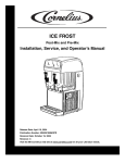
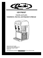
®
ICE FROST
Post-Mix and Pre-Mix
Installation, Service, and Operator’s Manual
Release Date: April 19, 2004
Publication Number: M620919596OPR
Revision Date: October 22, 2004
Revision: B
Visit the IMI Cornelius web site at www.cornelius.com for all your Literature needs.
ICE FROST POST-MIX AND PRE-MIX
INSTALLATION, SERVICE, AND
OPERATOR’S MANUAL
The products, technical information, and instructions contained in this manual are subject
to change without notice. These instructions are not intended to cover all details or variations of the equipment, nor to provide for every possible contingency in the installation,
operation or maintenance of this equipment. This manual assumes that the person(s)
working on the equipment have been trained and are skilled in working with electrical,
plumbing, pneumatic, and mechanical equipment. It is assumed that appropriate safety
precautions are taken and that all local safety and construction requirements are being
met, in addition to the information contained in this manual.
To inquire about current revisions of this and other documentation or for assistance with
any Cornelius product contact:
www.cornelius.com
1-800-238-3600
This document contains proprietary information and it may not be
reproduced in any way without permission from Cornelius.
Printed in U.S.A.
Copyright © 2004, All Rights Reserved, IMI Cornelius Inc.
TABLE OF CONTENTS
Important Warnings and Advice . . . . . . . . . . . . . . . . . . . . . . . . . . . . . . . . . . . . . . . . . 1
Technical Data . . . . . . . . . . . . . . . . . . . . . . . . . . . . . . . . . . . . . . . . . . . . . . . . . . . . . . . . 1
Plate data . . . . . . . . . . . . . . . . . . . . . . . . . . . . . . . . . . . . . . . . . . . . . . . . . . . . . . . . . 1
Transportation Indications . . . . . . . . . . . . . . . . . . . . . . . . . . . . . . . . . . . . . . . . . . . . . . 1
Installation . . . . . . . . . . . . . . . . . . . . . . . . . . . . . . . . . . . . . . . . . . . . . . . . . . . . . . . . . . . 2
Connecting the Electricity Mains . . . . . . . . . . . . . . . . . . . . . . . . . . . . . . . . . . . . . . . . 2
Connection Diagrams . . . . . . . . . . . . . . . . . . . . . . . . . . . . . . . . . . . . . . . . . . . . . . . . 3
Ice Frost Generic (Pre-mix) . . . . . . . . . . . . . . . . . . . . . . . . . . . . . . . . . . . . . . . . . 3
Ice Frost Generic (Post-mix) . . . . . . . . . . . . . . . . . . . . . . . . . . . . . . . . . . . . . . . . 4
Bowl Loading Operations . . . . . . . . . . . . . . . . . . . . . . . . . . . . . . . . . . . . . . . . . . . . . 5
Alarms . . . . . . . . . . . . . . . . . . . . . . . . . . . . . . . . . . . . . . . . . . . . . . . . . . . . . . . . . 5
Ice Frost Generic (Pre-mix) . . . . . . . . . . . . . . . . . . . . . . . . . . . . . . . . . . . . . . . . . . . . 6
Ice Frost Generic (Post-mix) . . . . . . . . . . . . . . . . . . . . . . . . . . . . . . . . . . . . . . . . . . . 7
Brix and Ratio Procedure . . . . . . . . . . . . . . . . . . . . . . . . . . . . . . . . . . . . . . . . . . 7
Programming Electronic Touch Pad . . . . . . . . . . . . . . . . . . . . . . . . . . . . . . . . . . . . . 8
Enter Time Programming on Initial Installation or in the Event of a Time Change 8
Setting COLD Timer (Night Setting) . . . . . . . . . . . . . . . . . . . . . . . . . . . . . . . . . . 9
Operate in Automatic Mode (with COLD Timer Activated) . . . . . . . . . . . . . . . . . 9
Operate in Manual Mode (without COLD Timer Activated) . . . . . . . . . . . . . . . . . 9
Setting the 12 or 24 Hour Display and oF or oC Temperature Display . . . . . . . 9
Viewing the Bowl Temperature . . . . . . . . . . . . . . . . . . . . . . . . . . . . . . . . . . . . . 10
Consistency Adjustment . . . . . . . . . . . . . . . . . . . . . . . . . . . . . . . . . . . . . . . . . . . . . 10
Quarterly Cleaning and Sanitation . . . . . . . . . . . . . . . . . . . . . . . . . . . . . . . . . . . . . . 11
Operations . . . . . . . . . . . . . . . . . . . . . . . . . . . . . . . . . . . . . . . . . . . . . . . . . . . . . . . . 11
Special Maintenance . . . . . . . . . . . . . . . . . . . . . . . . . . . . . . . . . . . . . . . . . . . . . . . . . . 15
Insufficient Air Flow Alarm . . . . . . . . . . . . . . . . . . . . . . . . . . . . . . . . . . . . . . . . . . . . 15
Electronic Monitoring . . . . . . . . . . . . . . . . . . . . . . . . . . . . . . . . . . . . . . . . . . . . . . . . .
Electronic Monitoring and Safety System . . . . . . . . . . . . . . . . . . . . . . . . . . . . . . . .
Pressure and Level Control Card General Features . . . . . . . . . . . . . . . . . . . . . . . .
Hardware Definitions . . . . . . . . . . . . . . . . . . . . . . . . . . . . . . . . . . . . . . . . . . . . . . . .
Legend . . . . . . . . . . . . . . . . . . . . . . . . . . . . . . . . . . . . . . . . . . . . . . . . . . . . . . .
Inputs Card . . . . . . . . . . . . . . . . . . . . . . . . . . . . . . . . . . . . . . . . . . . . . . . . . . . .
Outputs Card . . . . . . . . . . . . . . . . . . . . . . . . . . . . . . . . . . . . . . . . . . . . . . . . . . .
Operating Conditions . . . . . . . . . . . . . . . . . . . . . . . . . . . . . . . . . . . . . . . . . . . . . . .
OFF Condition . . . . . . . . . . . . . . . . . . . . . . . . . . . . . . . . . . . . . . . . . . . . . . . . . .
1st Filling Condition . . . . . . . . . . . . . . . . . . . . . . . . . . . . . . . . . . . . . . . . . . . . . .
Managing the Bowl Levels . . . . . . . . . . . . . . . . . . . . . . . . . . . . . . . . . . . . . . . .
Safety Probes (only for Ice Frost Generic Pre-mix) . . . . . . . . . . . . . . . . . . . . .
16
16
16
17
17
17
17
17
18
18
19
19
Wiring Diagram . . . . . . . . . . . . . . . . . . . . . . . . . . . . . . . . . . . . . . . . . . . . . . . . . . . . . . 21
VFCB (Pre-Mix) 115V/60Hz . . . . . . . . . . . . . . . . . . . . . . . . . . . . . . . . . . . . . . . . . . 21
VFCB (Post-Mix) 115V/60Hz . . . . . . . . . . . . . . . . . . . . . . . . . . . . . . . . . . . . . . . . . 22
VFCB (Pre-Mix) 230V/50Hz . . . . . . . . . . . . . . . . . . . . . . . . . . . . . . . . . . . . . . . . . . 23
VFCB (Post-Mix) 230V/50Hz . . . . . . . . . . . . . . . . . . . . . . . . . . . . . . . . . . . . . . . . . 24
Troubleshooting . . . . . . . . . . . . . . . . . . . . . . . . . . . . . . . . . . . . . . . . . . . . . . . . . . . . . 25
Ice Frost Operator’s Manual
IMPORTANT WARNINGS AND ADVICE
This instruction manual represents an integral part of the equipment and must be kept readily available
for use.
Read the warnings contained herein carefully before installing and using this equipment.
In addition to offering information concerning routine maintenance for the ice slush drinks machine and
technical back-up for troubleshooting, this manual aims to help the user make the most of the machine’s
potential, adapting it to suit the specific needs of the various countries it will be used in.
Modifications or attempts to modify the equipment will not only result in the forfeiture of the guarantee,
but are also extremely dangerous.
The maintenance operations must be carried out by qualified professionals. Never attempt to repair the
machine yourselves as the intervention of non-qualified persons, as well as being hazardous, could also
lead to serious damage to the machine.
TECHNICAL DATA
PLATE DATA
The voltage and the frequency are indicated on the serial number plate, located on the refrigeration deck
and the right hand side near the controls.
TRANSPORTATION INDICATIONS
To prevent the oil contained in the compressor from flowing out into the cooling circuit, the equipment
must be transported, stored, and handled in a vertical position, as per the indications given on the
packing.
The wooden pallet, equipped with housing for the lifting forks, allows the packed equipment to be moved
using normal handling and hoisting means.
© 2004, IMI Cornelius Inc.
-1-
Publication Number: M620919596OPR
Ice Frost Operator’s Manual
INSTALLATION
1.
2.
Release the equipment from the packing, then slide it off
upwards (see Figure 1).
Checking the machine identification after removing the
packing, you must check that the equipment you have
received is exactly as you ordered, making sure the
specifications indicated on the invoice or the delivery note
are identical to those on the data plate.
FIGURE 1
3.
Equipment accessories
The following accessories are included inside the bowls:
• This instruction manual;
• 1 tube of Vaseline to be used for the maintenance machine the requires;
• A drip tray.
The back-lit cover is packed separately from the machine.
4.
Positioning - make sure the machine’s bodywork is well ventilated, at least 6”, and do not install
near heat sources.
We recommend you keep the room temperature at between 59 and 77°F.
IMPORTANT: All the pieces of packing must be kept out of reach of children as they represent
potential hazards.
5.
Remove gear motor shipping pins and tags from the rear of the unit prior to installation.
CONNECTING THE ELECTRICITY MAINS
Before inserting the plug into the mains socket for your own
safety you must take careful note of the following precautions.
•
The machine’s electrical system can only be considered
safe when it is connected correctly to a grounded outlet, as
provided for by the national safety regulations. The
manufacturer cannot be held responsible for any damages
that may be caused by failure to earth the system.
•
For the system to be installed correctly and safely, it is
essential to provide a suitable socket having a dedicated 20
Amp circuit which complies with the national safety
standards in force (see Figure 2).
•
Check the power supply cable to make sure it is not being
crushed, do not use extension cords and, to remove the
FIGURE 2
plug, first turn OFF the switch, then hold the plug tightly and
pull gently.
• Do not obstruct the ventilation and the heat dissipation grids as bad airing, in addition to reducing the
output and causing bad functioning, could also lead to serious damage to the equipment.
IMPORTANT: If the power supply cord is damaged, it must be replaced by qualified persons only
to prevent any possible risks.
Publication Number: M620919596OPR
-2-
© 2004, IMI Cornelius Inc.
Ice Frost Operator’s Manual
CONNECTION DIAGRAMS
Ice Frost Generic (Pre-mix)
The diagram shows the sequence for the connection between the ICE FROST GENERIC PRE to an
existing pre-mix system.
FIGURE 3
Description:
1. Pre-mix product 1 inlet.
2. Pre-mix product 2 inlet.
4. Inlet for CO2 (coming from the pressure reducing valve, 12 psi).
5.
CO2 gas cylinder.
6.
7.
CO2 pressure regulator.
8.
9.
10.
11.
Gas cylinder pressure gauge.
Pre-mix product 1 container.
Pre-mix product 2 container.
Cooling unit (Optional).
Operating pressure gauge.
Connection:
Connect the points 1, 2, and 4 on the machine to the existing pre-mix system using quick couplings.
© 2004, IMI Cornelius Inc.
-3-
Publication Number: M620919596OPR
Ice Frost Operator’s Manual
Ice Frost Generic (Post-mix)
The diagram shows the sequence for the connection between the ICE FROST GENERIC POST to an
existing post-mix system.
FIGURE 4
Description:
1. Syrup 1 inlet.
2. Syrup 2 inlet.
3. Soda water inlet.
4. Inlet for CO2 45 to 60 psi.
5.
CO2 gas cylinder.
6.
7.
8.
9.
10.
11.
12.
13.
14.
15.
16.
17.
18.
Operating pressure regulator for carbonation unit.
Carbonation unit operating pressure gauge.
Unit and BIB operating pressure gauges.
Pressure regulator.
Gas cylinder operating pressure gauge.
Water Pressure regulator.
Filter.
Carbonation unit and optional precooling unit.
Syrup 1 pump.
Syrup 2 pump.
Bag-in-box exchanger.
Bag-in-box exchanger.
Bag-in-box.
Connection:
Connect the points 1, 2, 3, and 4 on the machine to the existing post-mix system using quick couplings or
.265 splice connectors.
Publication Number: M620919596OPR
-4-
© 2004, IMI Cornelius Inc.
Ice Frost Operator’s Manual
BOWL LOADING OPERATIONS
Alarms
NOTE: See Acronym Definitions on page 17.
Safety Probe Alarms (only for
ICE FROST GENERIC Pre-mix)
You will remember that the monitoring of the safety probes’ conditions (covered/uncovered) is only
active during the bowl loading phase. It follows, then, that a lack of liquid in the tanks during the nonloading phases will not be signalled.
When one of the two safety probes (SSIC1 and SSIC2) fails to detect the passage (presence) of liquid
during the loading phase, the system will stop (3-second software filter) the loading phase in progress,
while the buzzer on the machine emits an intermittent warning signal lasting 6 seconds.
The EVCARx connected to the unit where the lack of liquid has been detected by the SSICx can only be
energized by switching the system OFF then ON again. The functions linked to the EVPRESS will not
undergo any changes.
If both the safety probes (SSIC1 and SSIC 2) fail to detect a presence of liquid while the bowls are
loading, the buzzer on the card will emit an intermittent sound lasting approximately 20 seconds.
The actuators EVCAR 1 and EVCAR 2 are inhibited (OFF). The normal operation conditions can be
restored by switching the machine OFF then ON again using the main switch.
The EVPRESS solenoid valve is independent of the alarm signal and continues its CO2 gas
pressure reading function only (see relevant paragraph).
1st Filling Time-out
A time limit has been set for the first filling phase which is linked to the level probes SLIV 1 and SLIV 2’s
detection of the presence of liquid.
When one of the two probes (SLIV 1 and SLIV 2) fails to detect the presence of liquid for more than four
seconds, the buzzer on the card will emit an intermittent sound for approximately 6 seconds.
The EVCARx connected to the unit where the lack of liquid has been detected by the SSICx can only be
energized by switching the system OFF then ON again.
When both the level probes (SLIV1 and SLIV 2) fail to detect a presence of liquid for more than four
seconds, the buzzer on the card emits an intermittent sound lasting approximately 20 seconds.
All the actuators linked to the system are inhibited (EVCAR 1, EVCAR2, and EVPRESS =OFF). The
normal operating conditions can be resumed by switching the system OFF and then ON again.
Filling Time-out
A time limit has been set for the normal filling phase which is linked to the level probes SLIV 1 and SLIV
2’s detection of the presence of liquid.
When one of the two probes (SLIV 1 and SLIV 2) fails to detect the presence of liquid for more than one
minute, the buzzer on the card will emit an intermittent sound for approximately 6 seconds.
The EVCARx connected to the unit where the lack of liquid has been detected by the SSICx can only be
energized by switching the system OFF then ONN again.
When both the level probes (SLIV1 and SLIV 2) fail to detect a presence of liquid for more than on
minute, the buzzer on the card emits an intermittent sound lasting approximately 20 seconds.
The EVCAR 1 and EVCAR2 actuators are inhibited (OFF). The normal operating conditions can be
resumed by switching the system OFF and then ON again.
The EVPRESS solenoid valve is independent of the alarm signal and continues its CO2 gas
pressure reading function only (see relevant paragraph).
© 2004, IMI Cornelius Inc.
-5-
Publication Number: M620919596OPR
Ice Frost Operator’s Manual
“FILTER CLEANING” Alarm
A filter cleaning alarm will activate when the unit is running hot due to insufficient internal air circulation.
When this occurs a “Filtr” message will appear on the touch pad LED display readout and an intermittent
audible tone will also sound to alert the operator of this condition.
The “Filtr” message will appear when the alarm activates (a beeping sound every 4-5 seconds). To
determine the condition that caused the alarm and correct problem, see list of conditions below:
•
Condition
The filter is dirty and needs to be cleaned.
Corrective Action
• Clean and replace filter following instructions
(Removing and Cleaning Filter).
• Reposition unit to maximize ventilation space
(Installation Instructions).
•
The unit is positioned too close to a wall or
other object restricting air flow and causing
the machine to run at a higher temperature.
• The filter is not properly installed.
•
The unit has been installed near a heat
source, such as a coffee machine, ice maker
or cold beverage machine which expels hot
air from its vents, causing the machine to run
at a high temperature (installation near a
heat source should be avoided).
• Properly install filter (Removing and cleaning filter).
• Reposition unit to maximize ventilation space.
“SYSTEM OVER TEMPERATURE” Alarm
A system over temperature alarm will activate as a safety precaution when the unit has overheated to
protect the compressor.
•
The system automatically goes to “OFF” status where the compressor’s operations is stopped, while
augers will keep working to avoid forming ice blocks.
•
When this occurs an “Err” message will appear on the touch pad LED readout accompanied by a
continuous buzzer sound to alert the operator of this condition.
•
When this alarm activates, turn OFF all switches. Then determine the condition. (See “Filter Cleaning”
Alarm Section for Conditions and Corrective Actions).
ICE FROST GENERIC (PRE-MIX)
WARRNING: If the unit runs out of product, is turned off and turned back on without a new
(full) product tank installed the sensor will look for product for 4 minutes. During this 4
minute period CO2 will be pumped into the air.
•
Switch the machine’s main switch to the ON position (1).
•
Put the switch (A) into the ON position (1) see Figure 5,
switch A. Controls the flow of the product in the bowls.
•
The machine’s bowls will now fill up until the maximum level
is reached.
•
Continue with start up operations.
FIGURE 5
Publication Number: M620919596OPR
-6-
© 2004, IMI Cornelius Inc.
Ice Frost Operator’s Manual
ICE FROST GENERIC (POST-MIX)
•
Switch the machine’s main switch to the ON position (1).
•
Make sure the switch (L1) is in the OFF position (0) - Figure
6 - (switch L1 controls the flow of the products in the bowls).
•
Turn mixing motors OFF immediately. Do not run units with
bowls empty.
•
Using an 8 mm socket wrench (E1), loosen the nut that
holds the post-mix valve (D1).
•
Twist nozzle counter-clockwise (F1), lift the post-mix valve
(D1) up slightly and turn it towards the outside. leaving
nozzle and coupling attached to the bowl.
FIGURE 6
Brix and Ratio Procedure
•
Now pull the post-mix valve out further and tighten the 8mm
nut using the socket wrench (E1) - Figure 7.
•
Remove the post-mix valve’s nozzle and apply the relevant
dose calibrator/separator (G1), then the relative measuring
cup (H1) and push the micro switch on the valve (l1) until
both the soda water and the syrup run into the measuring
cup separately (Figure 8).
•
Check the BRIX: turn the water adjustment screw on the
solenoid valve clockwise to increase or counter-clockwise to
decrease the amount of water in the product.
•
When the desired mix has been found, remove the parts G1
and H1, replace the spout on the post-mix solenoid valve,
then position it in its original seating, performing the previous
operations in reverse order.
FIGURE 7
•
A refractometer may be used as an alternative to ratio
measurement.
• Repeat the same operations for the second bowl.
FIGURE 8
•
Once the adjustments have been carried out for each bowl, place the switch (L1) in the ON position
(1).
•
Both bowls will begin to fill up when the level sensor is activated.
•
Turn mixing motors ON (located on the control board).
•
Unit has built in delays for compressor and bowl fill switch.
•
During initial filling it is normal for some foaming to take place. Bowl level management will adjust as it
freezes down and foam will dissipate.
© 2004, IMI Cornelius Inc.
-7-
Publication Number: M620919596OPR
Ice Frost Operator’s Manual
PROGRAMMING ELECTRONIC TOUCH PAD
To lower the control cover, use a coin or other object to turn the keyless lock to the horizontal position, in
order to access the operating panel (controls are located on the right side of the unit).
Auger ON/OFF Button
Main Power Switch
• Turns unit ON.
o
o
• Selects 12/24 time or F /C temperature
display when turned ON while simultaneously
depressing the auger button.
• Sets current time when turned ON while
simultaneously depressing the “PRESS TO
SELECT FUNCTION” button.
• Turns auger ON and OFF when main
power switch is ON.
• Must be ON to permit COLD time to be
reset.
• Must be ON to activate the “PRESS TO
SELECT FUNCTION” button to select manual
“OFF”, “FREEZE”, or “COLD” functions.
FIGURE 9
PRESS TO SELECT FUNCTION Button
“AUTO TIMER” Button
• Used to manually select “OFF”, FREEZE”,
or “COLD” functions when auger is turned
ON.
• Turns auto COLD mode ON or OFF (light
on switch indicates when auto COLD mode is
activated).
• Accesses COLD timer reset mode when
depressed for an extended period when
auger is turned ON.
• Used to adjust the hours and minutes settings when readjusting current time or auto
COLD timer.
• Locks in hours, minutes and final time settings after they are reset using the “AUTO
TIMER” button.
• Does not function when light on “AUTO
TIMER” button is illuminated.
Enter Time Programming on Initial Installation or in the Event of a Time Change
1.
2.
Turn the power switch OFF.
Press and hold the left “PRESS TO SELECT FUNCTION” button and turn ON the power switch.
Release the “PRESS TO SELECT FUNCTION” button when the hour digits start blinking.
3. Set the hour by pressing the “AUTO TIMER” clock button until the appropriate hour is shown.
NOTE: When using a 12 hour clock the time is P.M. when the dot at the bottom right corner of the
LED display is lit; A.M. when dot is not lit.
4.
5.
Press the left “PRESS TO SELECT FUNCTION” button to set the minutes, then press the “AUTO
TIMER” clock button until the appropriate minutes are set.
Press the “PRESS TO SELECT FUNCTION” button one more time to save your settings.
Publication Number: M620919596OPR
-8-
© 2004, IMI Cornelius Inc.
Ice Frost Operator’s Manual
Setting COLD Timer (Night Setting)
1.
2.
3.
Turn the power switch ON. Make sure the “AUTO TIMER” is OFF (light on button is not lit).
Press the left hand “Auger ON/OFF” button ON.
Press and hold the “PRESS TO SELECT FUNCTION” button until you hear a long beep and the
LED, “Cold” and the “AUTO TIMER” clock light begins to blink.
4. Press the “AUTO TIMER” clock button to set the unit to COLD mode and then press the “PRESS
TO SELECT FUNCTION” button to save the setting.
5. Press the “AUTO TIMER” clock button to set the minutes to complete time setting that you want it to
turn to COLD mode. Then press the “PRESS TO SELECT FUNCTION” button to save the minute
setting. The “COLD” light will turn off and the “FROZEN” light and “AUTO TIMER” light will begin
blinking.
6. Set the time you want the machine to return to FROZEN mode by following steps 1 - 5 above. Then
press the “PRESS TO SELECT FUNCTION” button to save the time settings. The FROZEN light
should be blinking.
7. Repeat steps 1 - 6 for the opposite bowl using the left buttons.
NOTE: Once the settings have been saved, the unit will keep the settings, even when the power
switch is turned OFF.
NOTE: When the light on the “AUTO TIMER” clock button is “ON”, the COLD timer is activated. To
turn OFF the COLD timer, press the “AUTO TIMER” clock button(s) until the light(s) on the clock
button(s) turns off.
Operate in Automatic Mode (with COLD Timer Activated)
1.
2.
3.
4.
Turn power switch ON and wait for LED display to light up.
Press the left hand “Auger ON/OFF” button ON.
To operate in COLD mode press the “AUTO TIMER” button until it is illuminated.
When setting automatic times, please keep in mind it will take time for the frozen product to become
liquid or vice versa.
Operate in Manual Mode (without COLD Timer Activated)
1. Turn the power switch ON and wait for LED display to light up.
2. Make sure the clock button is OFF (LED light on clock button should not be lit up).
3. First turn auger ON by pressing the “Auger ON/OFF” button until it beeps.
NOTE: The auger must be ON before the unit will allow the COLD or FROZEN mode to be
activated.
4.
Then select COLD or FROZEN mode by pressing the “PRESS TO SELECT FUNCTION” button
until the light under the selection you desire is lit up.
NOTE: In the COLD mode, the LED will read the actual temperature of the product (the
temperature setting is preset to NSF standards and is not adjustable.) In the “FROZEN” or “OFF”
mode the LED will read the current time.
Setting the 12 or 24 Hour Display and
oF
or oC Temperature Display
1.
2.
Turn the power switch OFF.
Press and hold the left “AUGER ON/OFF” button and turn ON the power switch. Release the
“AUGER ON/OFF” button when either “12” or “24” are shown (indicates the current hour view).
3.
Press the “PRESS TO SELECT FUNCTION” button until either oF or oC is shown on the display.
4.
5.
Press the “AUTO TIMER” button until the desired temperature display type is shown (oF or oC).
Store the change by pressing the “PRESS TO SELECT FUNCTION” button until the current time is
displayed. The unit is now ready for use.
© 2004, IMI Cornelius Inc.
-9-
Publication Number: M620919596OPR
Ice Frost Operator’s Manual
Viewing the Bowl Temperature
1.
2.
Turn ON the auger on the side that you want to display the bowl temperature (press the “AGER ON/
OFF” button).
Press the “PRESS TO SELECT FUNCTION” button until the “Cold” LED is lit. The display will now
show the current bowl temperature in either oF or oC depending on which was selected.
CONSISTENCY ADJUSTMENT
1.
To dispense the product, place the cup beneath the tap (Q)
and lower the lever (R) very gently (Figure10).
2. Adjusting the consistency:
To vary the consistency of the ice slush, turn the knob (S)
as shown in Figure 11.
Turning the knob counter-clockwise will increase viscosity
(make the product denser).
Turning the knob clockwise will decrease viscosity (make the
product less dense).
FIGURE 10
ATTENTION: This device only changes the consistency of
the ice slush dispensed, it does not effect the COLD
temperature.
ATTENTION: When the level of the ice slush inside the bowl
is below the minimum, to stop the product becoming too
dense, you must switch off the COLD system (OFF
position), or top up the bowl, following the instructions
given in the previous paragraphs.
An indicator gauge for reference is located on the back of the
unit approximately 6 inches below the adjustment knob.
FIGURE 11
Publication Number: M620919596OPR
- 10 -
© 2004, IMI Cornelius Inc.
Ice Frost Operator’s Manual
QUARTERLY CLEANING AND SANITATION
OPERATIONS
ATTENTION: The cleaning operations must be performed with the machine disconnected from
the power supply.
1.
2.
3.
Empty the bowl of any remaining product and switch off the main switch “M”.
Remove the cover (B) - Figure 27.
With the post-mix version, see Figure 6 and 7 for details.
Extract the quick couplings (C2) / (F2) - (Figure 12, 13, and 14).
Pre-mix version
Post-mix version
FIGURE 12
FIGURE 13
FIGURE 14
4.
5.
Disconnect the probe fastenings (D2) / (E2) - (Figure 12 and 13).
Pull the lockpin/safety pin (Y) upwards - Figure15.
CAUTION: There is a spring below the safety pin. Take
caution when removing the pin that the spring does not fall
into the unit or eject the pin.
FIGURE 15
© 2004, IMI Cornelius Inc.
- 11 -
Publication Number: M620919596OPR
Ice Frost Operator’s Manual
6.
Slide the locking bar (Z) - Figure 16 - outwards so that the
bowls are fully released.
Unlock relief valve on the bowl lid cap and remove (Figure
17).
7.
Unscrew the knobs (A1) so the bowls can be lowered
slightly, open the tap to remove any remaining liquids and
then extract it from its seating, pulling it outwards (Figure
17).
FIGURE 16
Bowl Lid Cap
FIGURE 17
8.
Remove the tap from its seating, pressing the two
clamping wings at the same time (Figure 18) and pushing
upwards.
9.
Remove the tap, holding the body (R) pressed
downwards, then slide the lever (L) out of its seating
(Figure 19). Wash all the parts thoroughly with hot water
and mild detergent, rinse them well, and replace them.
FIGURE 18
FIGURE 19
10. Separate the bowl from its cover, releasing the fastening
(D1) by pulling them upwards as shown in Figure 20.
FIGURE 20
Publication Number: M620919596OPR
- 12 -
© 2004, IMI Cornelius Inc.
Ice Frost Operator’s Manual
11. Wash the bowl and cover carefully with water and mild
detergent, rinse them well, and replace them, making sure
the sealing strip (E1) is positioned correctly between the
cover and the bowl. To guarantee the seal, the rounded
part of the said sealing strip (as shown in Figure 21) must
be facing the cover.
FIGURE 21
12. Unscrew the fastening knob (F1) clockwise as the
direction indicated by the arrow (threading to the left) and
extract the spiral scraper (G1) and the seals (H1) and (I1).
Clean the individual parts thoroughly (Figure 22).
FIGURE 22
13. Clean the drip tray (J1) and the evaporator (K1) (Figure
23).
14. Replace the mixing unit as follows:
• Dampen the sealing strip (l1) and insert it into its
seating.
• Apply a generous amount of Vaseline (supplied with the
machine) to the suction cup seal (H1) (on the part that
comes into contact with the evaporator K1) and insert it
in its spiral seating.
• Replace the spiral scraper (G1).
• Fasten all the components in place by screwing the
knob F1 counter-clockwise.
15. Replace the bowl by pushing it into its seating.
16. Fasten the bowl in place by tightening the knobs (A1) Figure 24 and the locking bar (Z) - Figure 16.
FIGURE 23
FIGURE 24
© 2004, IMI Cornelius Inc.
- 13 -
Publication Number: M620919596OPR
Ice Frost Operator’s Manual
17. Replace the tap, remembering to smear both is seating in
the bowl and the seals (J) with Vaseline (Figure 25).
FIGURE 25
18. Remove the drip tray (L1) by rotating it slightly and pulling
it outwards (Figure 26).
Wash all the parts carefully and reassemble it by following
the prior operations, remembering to re-insert the
condensation discharge pipe (M1) in its seating.
FIGURE 26
Publication Number: M620919596OPR
- 14 -
© 2004, IMI Cornelius Inc.
Ice Frost Operator’s Manual
SPECIAL MAINTENANCE
ATTENTION: To guarantee the cooling system
a good performance level, the routine cleaning
of the condenser filter is essential.
As explained earlier, an audible signal accompanied by
the word FILT appearing on the control panel display,
will warn the operator when the filter is clogged and so
must be cleaned before the machine comes to an
automatic stop.
•
Disconnect the machine from the power supply;
•
Unscrew the nut (C in Figure 27).
•
Remove the cover (B in Figure 27).
•
Disconnect the plug (D in Figure 28).
•
Loosen and rotate the bracket.
•
Lift and remove the back (E in Figure 28).
•
Clean the filter behind the net, then clean the
condenser with a brush, if necessary.
WARRNING: You are reminded that all the operations described above must be carried out with
the machine switched off and the power cable disconnected.
FIGURE 27
FIGURE 28
INSUFFICIENT AIR FLOW ALARM
To protect the entire cooling system, the ice slush
drinks maker is fitted with an electronic system which
issues an acoustic warning signal in the event of
insufficient ventilation or if the condenser filter is
clogged with dust. In addition to this, the words FILT
and then ERR will appear on the control panel display.
FIGURE 29
If the operator does not intervene when the signal is
issued, restoring normal working conditions (i.e.
ensuring better ventilation or cleaning the filter), this
electronic system will stop the machine automatically.
FIGURE 30
© 2004, IMI Cornelius Inc.
- 15 -
Publication Number: M620919596OPR
Ice Frost Operator’s Manual
ELECTRONIC MONITORING
ELECTRONIC MONITORING AND SAFETY SYSTEM
The diagram shows the electronic pressures and levels
management system:
1.
2.
3.
4.
5.
Safety valve.
Monitoring card for maximum limit exceeded probes.
Bowl 1 overpressure discharge relief valve solenoids.
Bowl 2 overpressure discharge relief valve solenoids.
6
CO2 inlet solenoid valve.
5
6.
7.
Pressure and levels monitoring card.
CO2 pressure switch.
1
2
3
4
7
FIGURE 31
In addition to the product level probes, each bowl is fitted with 2 further ‘overfull’ safety probes.
In fact, if the level probes should cease functioning and so the product begins to fill up the bowls, these
safety probes will transmit this information electronically to the monitoring card (2), which will then
disconnect the pressures and levels monitoring card (6).
The pressures and levels control cards have various functions, which are described below.
PRESSURE AND LEVEL CONTROL CARD GENERAL FEATURES
Via a micro-controller, the µZ4LP allows the operator to manage the levels and the relative safety devices
linked to the two cold drink bowls. An electronic pressure switch card (amplified, linearized, and
compensated) is provided for monitoring the pressure of the gas used in the post-mix phase of the said
drink.
The Electronic Pressure Switch Card will have the following features:
•
Independent level control for each bowl.
•
CO2 gas pressure reading.
•
Acoustic warning signal in the event of a lack of liquid/s.
•
Pressure maintained between two pre-set points by means of a relay.
The use of these mixed THT and SMD components makes it possible to maximize the services/
dimensions/quality relationship (better immunity to external troubles).
The ECU is composed of two main printed circuits:
•
Power’ section including transformer, relay, and power supply.
•
Logic’ section including (controller and level control circuiting).
Publication Number: M620919596OPR
- 16 -
© 2004, IMI Cornelius Inc.
Ice Frost Operator’s Manual
ACRONYM DEFINITIONS
Legend
C
CS
R
PT
MR
VN
INT.
START
CSL
CLP
CCM
PRESS.
E.V. PRESS.
E.V. SCAR.
E.V. DOS.
electrovalve
M.DEV.
SO
I
Fan motor
Transformer
General switch
Compressor
Starting capacitor
Starting compressor relay
Overload protector
Gear motor
Fan motor
Control levels switch
Light cover switch (rev. 00)
Ignition light cover neon
Light cover neon
Light cover neon reactor
Bowls level safety control
Bowls level and pressure control
Compressors and gear motors control
2,5 bar air pressure switch
Bowls pressure electrovalve Ø 1
Charging overpressure discharge electrovalve Ø 3
Product charging electrovalve for Pre-mix or syrup and soda proportioning
Post-mix proportioning valve microdeviator
Product control (coke)
Lights 0-1 switch arrangement (rev. 01)
Inputs Card
1.
2.
3.
4.
5.
SLIV1
SLIV2
SSIC1
SSIC2
SPRESS
Bowl 1 level probe input
Bowl 2 level probe input
Bowl 1 safety probe input
Bowl 2 safety probe input
Pressure sensor input
Outputs Card
1.
2.
3.
EVCAR 1
EVCAR 2
Bowl 1 filling solenoid valve
Bowl 2 filling solenoid valve
EVPRESS
CO2 gas enabling solenoid valve
OPERATING CONDITIONS
The µZ4LP system has 4 main functioning conditions:
•
OFF condition.
•
1st FILLING condition.
•
BOWL LEVEL MANAGEMENT condition.
•
CO2 GAS PRESSURE management.
© 2004, IMI Cornelius Inc.
- 17 -
Publication Number: M620919596OPR
Ice Frost Operator’s Manual
OFF Condition
In this condition, the electronic card is not connected to the power supply. To connect the ECU to the
power supply, the main system switch must be put in the ON position.
1st Filling Condition
Supposing both the bowls are empty when the power is switched ON, the following situation will occur:
After a 3 second delay if the four probes, managed by the system, have detected no ‘presence’ of liquid,
the (µcontroller will energies the EVCAR 1 AND EVCAR 2 actuator to allow the correct level refill phase
to begin.
FIGURE 32
Following the system flow, the first probes to be ‘covered’ are the two SSIC1 and SSIC2. However, this
recognition of the passage of liquid does not actually stop the filling phase since the main ‘aim’ of the
ECU is to fill the two bowls to the level required. Therefore only the recognition by SLIV 1 and SLIV 2
interrupts the inlet of liquid into the bowl/s.
FIGURE 33
Once the 1st filling phase is complete, if necessary (see chapter on pressure levels management) the
(µcontroller will enable the EVPRESS, which has been kept forcibly de-energized.
NOTE 1: The 1st loading phase must take place within a maximum time lapse which is controlled by the
(controller (see Alarms section).
NOTE 2: The 1st loading phase may only concern one of the two bowls, but it will maintain the same
features.
NOTE 3: If all the probes are covered when the system is switched ON, the EVPRESS functioning is
enabled.
Publication Number: M620919596OPR
- 18 -
© 2004, IMI Cornelius Inc.
Ice Frost Operator’s Manual
Managing the Bowl Levels
When one of the two level probes (SLIVx) fails to detect the presence of liquid in the bowl, the EVCARx
is enabled to restore the correct level.
The probes relating to each bowl are completely independent, therefore the following situation will occur:
FIGURE 34
FIGURE 35
NOTE 1: The level/s refill phase must take place within a maximum time lapse which is controlled by the
(controller (see Alarms chapter).
NOTE 2: The level/s refill phase may only concern one of the two bowls, but it will maintain the same
features.
NOTE 3: It is essential that the safety probes are covered for the bowl/s filling phase to take place.
Safety Probes (only for ICE
FROST GENERIC Pre-mix)
In addition to the two level probes relating to the two bowls (see FIGURE 32 through FIGURE 35), the
µZ4LP system also monitors the two ‘safety’ probes designed to monitor the presence of liquid in the
external tanks.
The monitoring of the condition of the safety probes (covered/uncovered) is only active during the bowl
loading phase. It follows, then, that a lack of liquid in the tanks during the non-loading phases will not be
signalled.
If: SSIC1 “KO” when EVCAR 1 = OFF SSIC2 “KO” when EVCAR 2 = OFF -
no signal
no signal
Example of how the safety system works:
Supposing the safety probe SSIC 1 is uncovered and the solenoid valve EVCAR 1 is de-energized. In
this case there will be no signal.
Then the level probe SLIV 1 located in the bowl 1 is uncovered. The solenoid valve EVCAR 1 is enabled
to allow the bowl 1 to fill up correctly.
© 2004, IMI Cornelius Inc.
- 19 -
Publication Number: M620919596OPR
Ice Frost Operator’s Manual
3 seconds (software hysteresis) after the activation of the solenoid valve EVCAR 1, the safety signal is
activated as the probe SSIC 1 has been identified as uncovered. The loading solenoid valve EVCAR 1 is
therefore deactivated and the buzzer emits an intermittent signal lasting 6 seconds.
NOTE 1: the same intervention methods are applied when the safety probe
is uncovered after the solenoid valve EVCAR 1 has been activated.
NOTE 2: the 3-second software filter activated when it detects the safety probe is uncovered and the
relevant signal have been introduced to prevent the probe recognizing the “tank-bowl” conduit as “empty”
when there is residual gas in it.
Summing Up:
• When one of the two safety probes SSICx fails to detect the passage (presence) of liquid during the
loading phase, the system will stop (3-second software filter) the loading phase in progress, while
the buzzer on the machine emits an intermittent warning signal lasting 6 seconds.
•
If the safety probes SSICx is uncovered when there is no loading phase in progress (therefore
EVCARx is de-energized), no alarm signal is emitted.
This signal is activated as soon as the system starts to load the bowl.
If: EVCAR1 = ON and SSIC1 = OK
EVCAR2 = ON and SSIC2 = OK
If: EVCAR1 = ON and SSIC1 = KO
EVCAR2 = ON and SSIC2 = KO
bowl 1 is filled as usual
bowl 2 is filled as usual
after 3 seconds - EVCAR 1 = OFF and buzzer is activated
after 3 seconds - EVCAR 2 = OFF and buzzer is activated
ATTENTION: After the no liquid alarm signal has been activated (SSICx uncovered), the actuators
for the bowl whose safety probe is uncovered cannot be re-activated. Full functioning conditions
can only be restored by switching the machine OFF then ON again and re-starting from the 1st
filling phase. When the second safety probe is also identified as uncovered, all the charges
relating to the system are inhibited (with the exception of EVPRESS) and the buzzer emits an
intermittent sound for approximately 20 seconds. Full functioning conditions can only be
restored by switching ON and OFF the machine starting from the 1st filling phase.
The EVPRESS solenoid valve is independent of the alarm signal and continues its CO2 gas
pressure reading function only (see relevant paragraph).
Publication Number: M620919596OPR
- 20 -
© 2004, IMI Cornelius Inc.
Ice Frost Operator’s Manual
WIRING DIAGRAM
VFCB (PRE-MIX) 115V/60HZ
FIGURE 36
© 2004, IMI Cornelius Inc.
- 21 -
Publication Number: M620919596OPR
Ice Frost Operator’s Manual
VFCB (POST-MIX) 115V/60HZ
FIGURE 37
Publication Number: M620919596OPR
- 22 -
© 2004, IMI Cornelius Inc.
Ice Frost Operator’s Manual
VFCB (PRE-MIX) 230V/50HZ
FIGURE 38
© 2004, IMI Cornelius Inc.
- 23 -
Publication Number: M620919596OPR
Ice Frost Operator’s Manual
VFCB (POST-MIX) 230V/50HZ
FIGURE 39
Publication Number: M620919596OPR
- 24 -
© 2004, IMI Cornelius Inc.
Ice Frost Operator’s Manual
TROUBLESHOOTING
NOTE: The following procedures must be performed by a qualified service technician.
Problem
“Filt” or “Err” message appears on
the touchpad LED readout
The machine does not cool, or
cools only partially, but the compressors are running
The machine does not cool or
cools only partially, but one or
more of the compressors are not
running
Possible Cause
Solution
• The filter is dirty and needs to
be cleaned
• Clean and replace filter following instructions (Removing and
Cleaning Filter)
• The unit is positioned too close
to a wall or other object restricting air flow and causing the
machine to run at a higher temperature
• Reposition unit to maximize
ventilation space (see installation figures)
• The filter is not properly
installed
• Properly install filter see
“Removing and cleaning filter”
• The unit has been installed
near a heat source, such as a
coffee machine, ice maker or
cold beverage machine which
expels hot air from its vents,
causing the machine to run at a
high temperature. (Installation
near a heat source should be
avoid)
• The space around the machine
is inadequate for ventilation
• Reposition unit to maximize
ventilation space (see installation figures)
• Freezer is in COLD mode
• Return to FROZEN mode
• The condenser fins are clogged
with airborne particles
• Remove the side panels. Using
a brush or compressed air
clean the condenser
• Fan motor is not running
• Check the fan motor’s electrical
connections and, if disconnected, reconnect. If still not
operating, replace the motor
• Refrigerant is low
• Locate the leak, eliminate it and
recharge the system
• Replace the malfunctioning compo-
• Defective Electrical components
• Loose wire connections
• One or more of the compressors
are malfunctioning
• No current is coming to the
“compressor delay” PC board
• Allow at least 8” (20cm)
between the machine and anything next to it; keep away from
heat sources
nents
• Check the contacts and correct
those that are incomplete
• Replace the compressor(s)
• Check the electrical connections to
the PC board as well as the transformer feeding the PC board and
correct
© 2004, IMI Cornelius Inc.
- 25 -
Publication Number: M620919596OPR
Ice Frost Operator’s Manual
Problem
The machine over-freezes making
the auger movement slow or
stopped
Possible Cause
• The product Brix/ratio is too low
• Check the product Brix/ratio and
• The screw setting for the product
• Reset the screw toward the “-”
correct
consistency control system is set
too far toward the “+” position
• The limit switch arm is bent away
from the gearmotor and prevents
contact
• The level of the product in the bowl
is too low, exposing the auger
• The compressor PC board contacts
don’t open
The machine is noisy
The main power switch is “On”.
The unit is not running.
• Using pliers, straighten the limit
switch arm
• Add more product or turn the refrigeration “Off”
• Replace the PC board
• Check and correct
• The pressure cutout switch has
• Clean the condenser or add venti-
• Replace the fuse(s)
lation space around the machine
(the cutout switch reset is automatic when the conditions are corrected)
• Some electrical connections are
not complete
Product is leaking from the dispensing valve
position to produce a thinner consistency product
• The fan motor blades are hitting
internal components
• The fuse(s) are blown
activated
Product is leaking out of the bowl
Solution
• Check the contacts and correct
those that are incomplete
• The main power is not functioning
• One of the bowl seals is not in
place
• The dispensing valve has been
• Replace the switch
• Replace or reposition the seals
• Reassemble and replace
incompletely or incorrectly replaced
in its position
• The free movement of the dispensing valve is impeded
• Dispensing valve o-rings are dam-
• Clean and lubricate the valve and
valve cylinder with the lubricant
provided with the machine
• Replace the o-rings
aged
Product is flowing into drain tray
through drainage tube
• The bell shaped “shaft” seal
between the front of the cylinder
and the auger hub has not been
reinstalled properly
• The bell shaped “shaft” seal or the
spindle bushing seal is damaged or
worn
The auger is not turning
• Find the seal and put it back in
place
• Replace the damaged/worn seal
and check the condition of the
driveshaft.
• Auger not turned on
• Turn auger on
• Some electrical connections are
• Check the contacts and correct the
not complete
ones that are incomplete
• The gear motor(s) are malfunction-
• Replace the gear motor(s)
ing
The auger is creating noises as it
rotates
• The large red bowl seal is not in
• Check and correct
position, causing the gear teeth not
to mesh
• The product brix is incorrect
• Check the product brix and correct
• The bell shaped “shaft” seal has
• Replace or Clean and lubricate
been replaced without lubrication
or is damaged
• The auger has been incompletely
with the lubricant provided with the
machine
• Check and correct
or incorrectly reassembled (ie the
auger’s gear pins are not properly
seated)
Publication Number: M620919596OPR
- 26 -
© 2004, IMI Cornelius Inc.
Ice Frost Operator’s Manual
Problem
Cap is leaking
Bowl not refilling
Bowl is overfilling
CO2 leaking from back of unit
Possible Cause
Solution
• The nut is loose
• Out of syrup
• Tighten the nut
• Replace
• Out of CO2
• Replace
• Valves are shut off or blocked
• Open
• Foam covering probes
• Wait
• Fill Switch in off position
• Turn on
• Defective syrup pressure switch
• Replace
• Defective CO2 shut off
• Replace
• Bad Pressure and Levels Card
• Proper function of bowl over
pressure discharge solenoids
• Replace the card
• If not continuous leak it is normal operation
• Poor connection
• Repair leak
WARRNING: Relief valve venting is normal, a continuous leak is not and must be corrected immediately. Repair the solenoid valve.
© 2004, IMI Cornelius Inc.
- 27 -
Publication Number: M620919596OPR
Ice Frost Operator’s Manual
Publication Number: M620919596OPR
- 28 -
© 2004, IMI Cornelius Inc.
IMI Cornelius Inc.
www.cornelius.com
1-800-238-3600