1
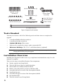
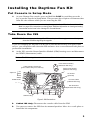
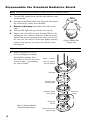
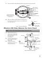
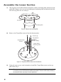
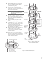
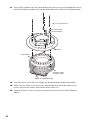
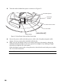
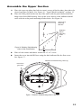
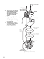
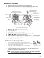
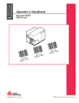
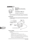
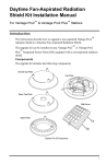
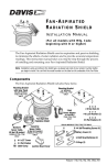
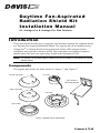
Dayt i m e Fa n - A s pir ate d
Radiation Shield Kit
Installation Manual
for Vantage Pro & Vantage Pro Plus Stations
Introduction
These instructions describe how to upgrade a non-aspirated Vantage Pro radiation shield
to a Daytime Fan-Aspirated Radiation Shield. The upgrade kit can be installed on any
Vantage Pro® or Vantage Pro Plus Integrated Sensor Suite (ISS) equipped with a
round-plate non-aspirated, radiation shield. The round-plate non-aspirated radiation
shield replaced the previous square-plate shield at the beginning of 2003.
Note: The Daytime Fan-Aspirated Radiation Shield Kit can only be installed on round-plate non-aspirated
radiation shields.
Components
The upgrade kit includes the items shown in “Figure 1” and “Figure 2”.
Closed Cap Plate
Fan Unit
Solar Panel &
Mounting Bracket
Open Cap Plate
Fan Plate
Open Plate
Figure 1. Daytime Fan Kit Components
Product # 7745
#8-32 x 1/2" Screws (3)
#8-32 x 3-1/4"
Screws (3)
Threaded Spacers (3)
Power Cable
Assembly
#8 Split-Lock Washers (6)
Cable Tie Mount
#8 Flat Washers (6)
#4 x 3/8" Screw
#4 Flat Washer
Cable Clamp
4" Cable Tie
12" Cable Ties (2)
Figure 2. Daytime Fan Kit Hardware
Tools Needed
You may need some or all of the following tools and other items to complete the
upgrade:
•
A medium Phillips-Head screwdriver
•
A medium slot-tip screwdriver
•
Cabled ISS Only: Wire cutters
•
Other tools as required to remove and re-mount the ISS
•
Wireless ISS Only: CR-123A 3-volt lithium battery (optional)
Note: If you are upgrading an ISS that has been in service for a year or more, you should consider
changing the ISS battery during the upgrade.
Installation Over view
Installing the Daytime Fan Kit is not very complicated and should take only 30 to 60
minutes to complete.
These are the steps to install the Daytime Fan components:
1.
2.
3.
4.
5.
6.
7.
8.
9.
2
Put the console into Setup Mode.
Take the ISS down from its installed position.
Disassemble the standard radiation shield.
Remove the solar panel if you have a Wireless ISS.
Assemble the lower section of the fan-aspirated shield.
Install the fan unit.
Assemble the upper section of the fan-aspirated shield.
Re-Install the ISS.
Take the console out of Setup Mode.
Installing the Daytime Fan Kit
Put Console in Setup Mode
1.
At your Vantage Pro console, press and hold the DONE key and then press the key to put the console in Setup Mode. This prevents the reception of erroneous data
from the rain collector while you are removing the ISS.
Note: If the console acquires erroneous data during the upgrade, refer to “Take the Console Out of Setup
Mode” on page 14 for instructions on clearing data. Additional information on clearing and setting
console data can be found in the “Vantage Pro Console Manual.”
Take Down the ISS
CAUTION: Please work on your Vantage Pro ISS in a safe place. We strongly recommend that you take
down the ISS before beginning the upgrade.
If you are installing the Daytime Fan Kit on an ISS that has already been placed into
service, you will need to take down the ISS and move it to a convenient and safe place to
perform the installation.
1.
At the ISS, open the Sensor Interface Module (SIM) housing cover and disconnect
the WIND (anemometer) cable.
Note: The SIM housing is located on the bottom of the radiation shield.
Cable Routing Channels
(press cables fully into channel)
Optional
UV
SUN
3-Volt Lithium Battery
(Wireless ISS Only)
Solar Panel Power
(Wireless ISS Only)
AC Power
(optional)
RAIN
WIND
TEMP HUM
Console Cable
(Cabled ISS Only)
DIP Switches
(Wireless ISS Only)
SIM Housing
Figure 3. SIM Connections
2.
Cabled ISS Only: Disconnect the console cable from the SIM.
3.
You can now remove the ISS from its mounted position. Move it to a safe place to
install the kit components.
3
Disassemble the Standard Radiation Shield
Note: We recommend using a workbench or table to perform the following procedures.
1.
2.
3.
4.
5.
Turn the ISS upside down with the rain collector cone
on the bottom.
Disconnect the RAIN cable and, if present, disconnect
the SUN and UV cables from the SIM.
Wireless ISS Only: Disconnect the solar power
cable.
Turn the ISS right-side up with the cone on top.
Remove the rain collector cone from the ISS base by
rotating the cone counter-clockwise. When the cone’s
latches line up with openings in the base, you can lift
the cone off. The cone fits in the base tightly and may
require extra pressure to remove the first few times.
See Figure 4.
Tip:
6.
Twist to Open
Figure 4. Remove Rain
Collector Cone
Steady the ISS base between your knees when removing the cone.
Remove the three 8-32 x 4”
screws holding the radiation
shield plates together. Save
these three screws for use in the
next procedure, “Assembling
the Lower Shield.”
#8-32 x 4" Screw
#8 Lock Washer
#8 Flat Washer
ISS Base
Top Plate with
Insulating Disk
Radiation Shield
Open Plates
Temp/Hum
Sensor
Figure 5. Standard Radiation
Shield Assembly Diagram
4
Bottom Plate with
SIM Housing
Temp/Hum
Cable
7.
Route the RAIN cable behind the drain and out the hole near the drain.
ISS Base
Rain Collector
Tipping Bucket
Drain
RAIN Cable
Install Cable
Tie Mount
Here
Route Cable Here
Figure 6. Route RAIN
Cable Around Drain and
through Hole
8.
Place the adhesive-backed cable tie mount next to
the hole near the drain, and secure the cable with
the small cable tie.
Cable Tie
RAIN Cable
Figure 7. Secure the RAIN Cable
Cable Tie
Mount
Route Cable
Through Hole
Wireless ISS Only: Remove the Solar Panel
Note: A new solar panel included with the kit replaces the original solar panel.
1.
2.
3.
Insert a slot-tip screwdriver between the solar
panel retaining tabs and
the solar panel.
See Figure 8. .
Pry the retaining tabs out
just enough to free the
solar panel.
Lift the solar panel
straight up to remove it
from the ISS base.
3
Lift solar panel to remove.
Solar Panel
Solar Panel
Retaining Tabs
2
Pry tab out to
release solar panel.
1
Insert screwdriver
between tab and
solar panel.
Figure 8. Remove the Solar Panel
5
Assemble the Lower Section
1.
The top plate in the ISS radiation shield has a thick, insulating disk attached on the
underside. Remove the two screws holding the insulating disk and discard the disk.
Save the top plate for use in Step 3.
Top Plate
Insulating Disk
Figure 9. Remove the Insulating Disk
2.
Remove the Temp/Hum sensor from the bottom plate.
Screws (3)
Flat Washer
Temp/Humidity
Sensor
Cable Clamp
Cable Clamp
Mounting Hole
Figure 10. Temp/Hum Sensor Removal and Installation
3.
Using the same screws and orientation, install the Temp/Hum sensor on the top
plate from Step 1.
Note: The cable clamp mounting hole is missing from the closed plates on early production models. If
it is missing on your ISS, discard the clamp and hardware. The extra strain relief provided by
the clamp will not be necessary for most applications.
6
4.
5.
Start building the lower section of
the new radiation shield with the
original bottom plate.
Place the new Temp/Hum plate
from Step 3 and two open plates on
top of the bottom plate.
Note: When stacking plates, make sure
the screw bosses (holes) line up
with each other.
Open Plate
TEMP HUM
Sensor Cable
Open Plate
6.
Run the TEMP HUM cable over the
top of second open plate directly
above the cable port openings in the
SIM housing.
7. Place the third open plate on the
stack.
8. Using the #8-32 x 1/2” screws and
three of the #8 washers and #8 lock
washers included with the kit,
attach the three threaded spacers to
the fan plate. See Figure 11.
9. Place a #8 lock washer and then a #
8 flat washer on one of the 4”
screws removed from the original
radiation shield.
10. Insert the 4” screw with washers
into one of the radiation shield plate
holes located just counter-clockwise
from a threaded spacer.
Open Plate
Closed Plate
with
Temp/Hum
Sensor
Closed Plate
with SIM
Note:
Route TEMP
HUM Sensor
Cable out on
the Cable Port
Side of the
SIM Housing
SIM
Cable
Port
Openings
SIM
Housing
Threaded Spacers (3)
Figure 11. Radiation Shield Lower
Section Assembly Diagram
Fan Plate
#8 Flat Washer
#8 Lock Washer
#8-32 x 1/2" Screw
Figure 12. Install Threaded Spacers
7
11. Lower the Fan Plate onto the stack making sure the screw goes through the boss in
each of the plates and lines up with the threaded insert located in the bottom plate.
#8-32 x 4" Screws (3)
#8 Lock Washer
#8 Flat Washer
Fan Plate
Screw Boss
Threaded Insert
in Bottom Plate
Figure 13. Install Fan Plate
12. Turn the screw a few times to engage the threaded insert in the bottom plate.
13. Make sure the other screw bosses are aligned and then insert the other two 4”
screws with a lock washer and washer in the same way.
14. Tighten all three screws to securely fasten the bottom section of the radiation
shield.
8
Install the Fan Unit
1.
Place the fan unit into the center of the fan plate. See Figure 14.
Solar Panel &
Mounting Bracket
Fan Unit
Fan Cable
Solar
Power
Cable
3-Pin
Connector
2-Pin
Connector
Put Power Cable
Clamp Here
Power Cable
Assembly
Important - Cabled ISS Only!!
Cut Connector Module off the Power Cable
Assembly before connecting fan or solar panel.
Keep the Connector Module
Cut Here
Discard the rest of the cable
Figure 14. Install Fan Unit
2.
3.
4.
Cabled ISS Only: Because the SIM in a cabled ISS receives power from the
console, we recommend you cut the power cable next to the connector module and
discard the cable. Save the connector module for use in Steps 3 and 4. See Figure
14.
Plug the fan cable into the 3-pin connector on the connector module.
Plug the solar panel cable into the 2-pin connector on the connector module.
9
5.
Tuck the cables behind the spacer as shown in Figure 15..
Threaded Spacer
Connector
Module
Solar Power Cable
Fan Unit Cable
Cable Clamp
Power Cable to SIM
(Wireless ISS Only)
Figure 15. Clamp Power Cable and Solar Power Cable
6.
7.
Secure the power cable and solar power cable to the fan plate using the cable
clamp, #4 screw and washer included with the kit.
Make sure the fan blades rotate in a counter-clockwise direction by taking the
radiation shield assembly to an area exposed to sunlight or by shining a bright
incandescent light on the solar panel.
If the fan blades rotate in the wrong direction, check the fan and solar power cables
for a reversed connection.
Note: The fan must rotate in a counter-clockwise direction in order to operate effectively.
10
Assemble the Upper Section
1.
2.
Place the open cap plate (has hole in center) on top of the fan plate, then place the
closed cap plate (no hole). See Figure 18. ‘ Upper Shield Assembly” on page 12.
Place the solar panel bracket on top of the stack with the panel located near the
hinge side of the SIM housing. Line up the screw bosses in the radiation shield
stack with the solar panel mounting bracket holes. See Figure 16.
Solar Panel
Mounting
Bracket
Radiation
Shield
Mounting
Holes
(3)
Figure 16. Radiation Shield Mounting
Holes in Solar Panel Bracket
3.
4.
Place a lock washer and then a washer on a 3 1/4” screw.
Insert the screw into the ISS base using the hole indicated for the first screw.
See Figure 17. .
Radiation Shield Mounting Holes (3)
First screw
goes here
Figure 17. Radiation Shield Mounting Holes in ISS base
11
Insert this screw first
#8-32 x 3-1/4"
Screws (3)
5.
6.
7.
Lower the ISS base onto the
stack so that the screw goes
into the boss nearest the
solar panel.Turn the screw a
few times to engage the
threads.
Place a lock washer and
washer on the other two
3 1/4” screws then insert
them through the remaining
two screw holes.
Tighten all three screws to
securely fasten the radiation
shield and solar panel
bracket to the ISS base.
#8 Lock Washers
#8 Flat Washers
ISS Base
Rain
Collector
Cable
Solar Panel
& Bracket
Closed Cap Plate
(no hole)
Solar
Power
Cable
Open Cap Plate
(hole in center)
Fan Plate
Power Cable
(Wireless ISS Only)
Figure 18. Upper Shield Assembly
12
Re-Install the ISS
1.
Install the rain collector cone and turn the ISS upside down.
Open the SIM cover and connect the TEMP/HUM and RAIN sensor cables.
If installed on your station, connect cable for the UV and SUN sensors.
2.
3.
Cable Routing Channels
(press cables fully into channel)
Optional
3-Volt Lithium Battery
(Wireless ISS Only)
UV
SUN
RAIN
WIND
Power Cable
(Wireless ISS Only)
AC Power (optional)
Console Cable
(Cabled ISS Only)
TEMP HUM
DIP Switches
(Wireless ISS Only)
Figure 19. SIM Cable Connections
4.
Wireless ISS Only: Connect the power cable.
5.
Close the SIM cover.
Re-install the ISS in its previous location.
7. Open the SIM cover and connect the WIND (anemometer) cable.
8. Cabled ISS Only: Connect the console cable.
9. Close the SIM cover and fasten the cover using two #6 x 1/2” (3.5mm x 12mm)
self-threading screws. Without the screws the SIM cover can be blown off the
housing in extremely windy conditions.
10. Use cable ties to secure cables.
6.
Guidelines for Securing Cables
•
Secure cables so they will not whip about in the wind.
•
Secure cables to metal poles by using a cable tie or by wrapping electrical tape around them both.
Cable Tie
Cable Clip
Figure 20. Securing Ca
•
Place clips or ties approximately every 3 to 5 feet (1 to
1.6 m).
•
If needed, additional cable ties, cable tie mounts, and other hardware can be
obtained at a hardware or electronics store.
Note: Do not use metal staples or a staple gun to secure cables. Metal staples—especially when
installed with a staple gun—have a tendency to cut the cables.
13
Take the Console Out of Setup Mode
1.
2.
At your Vantage Pro console, press the DONE key to take the console out of Setup
Mode.
Check the console for erroneous rain data and clear if necessary.
To clear erroneous data:
a. Select the weather variable to be cleared.
b. Press and release the 2ND key, then immediately press and hold the CLEAR
key.
The daily rain reading will start blinking.
c. Keep holding CLEAR until the reading changes to zero.
d. Refer to your Vantage Pro Console Manual for more information on setting
3.
and clearing weather variables.
Congratulations! You have completed the upgrade and can now enjoy your daytime
fan-aspirated radiation shield.
Maintenance
•
Keep the surfaces of the ISS clean, since the radiation shield and solar panel are
less effective when dirty. Remove dust from the solar panel and radiation shield
with a damp cloth.
•
Remove any debris obstructing air flow through the radiation shield such as leaves,
twigs, webs, and nests.
•
Do not spray the ISS with insecticides of any kind. Some insecticides can damage
the sensors and even damage the radiation shield.
Annual Maintenance
We recommend cleaning out any debris that may have accumulated inside the radiation
shield and replacing the motor (# 7758) on an annual basis.
1.
2.
3.
4.
5.
6.
7.
8.
14
Remove your fan-aspirated ISS and place on a stable work surface.
Disassemble the radiation shield.
Remove any debris lodged inside the unit.
Clean the surfaces of the radiation shield with a damp cloth.
Unplug the old fan unit and remove from it from the radiation shield.
Install the new fan unit (#7758) and plug it into the Junction Board.
Assemble the Radiation Shield.
Re-install the ISS in its previous location.
Troubleshooting
If you are experiencing problems performing the upgrade or have problems with your
Daytime Fan-Aspirated Radiation Shield, first be sure to check all cable connections. If
you are unable to solve the problem, please call Davis Technical Support. We’ll be glad
to help. Most questions can be answered over the phone. You can also email us for
support or visit our website. Sorry, we are unable to accept collect calls.
Note: Please do not return items to the factory for repair without prior authorization.
Contacting Davis Instruments
(510) 732-7814 for Technical Support, Monday – Friday, 7:00 a.m. – 5:30 p.m. Pacific
Time.
(510) 670-0589 – Fax to Customer Service or Tech Support.
[email protected] – E-mail to Technical Support.
[email protected] – General e-mail.
www.davisnet.com – Copies of user manuals and other product documents are avail-
able on the “Support” page. Watch for FAQs and other updates. Subscribe to the
e-newsletter.
15
© Davis Instruments Corp. 2003-2004. All rights reserved.
Daytime Fan-Aspirated Radiation Shield Kit Installation Manual
Rev B, January 16, 2004
Document: 07395.033
Product: 7745
Vantage Pro is a registered trademark of Davis Instruments Corp.
This product is protected in the United States by Patent Number 6,247,360.
3465 Diablo Avenue, Hayward, CA 94545-2778 U.S.A.
510-732-9229 • Fax: 510-732-9188
E-mail: [email protected] • www.davisnet.com