1
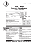
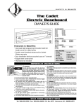
OWNER’S GUIDE
MODELS:
EBHN500
EBHN750
EBHN1000
EBHN1250
EBHN1500
EBHN500-8
EBHN750-8
EBHN1000-8
EBHN1250-8
EBHN1500-8
Features & Benefits
•
Whisper quiet operation and low surface temperatures
•
Filled with non-toxic, non-hazardous thermal fluid
•
Self-contained hermetically sealed element design requires no
plumbing, piping, or other water supply
•
Thermal fluid capacity offers better heat retention, which creates
less cycling and keeps more consistent room temperatures
•
Designed to reduce the effects of indoor allergens
•
7-year element warranty
TOOLS REQUIRED
• Phillips Screwdriver
•
Straight Screwdriver
• Wire Strippers
• Drill or Hammer
• Level
• Punch or Chisel
• Drill Bits
•
Utility Knife
• (4) Wood Screws
• (3) Wire Nuts
• (1) Strain Relief Connector
IMPORTANT INSTRUCTIONS
WARNING!
Turn the electrical power off at the electrical panel
board (circuit breaker or fuse box) and lock or tag the
panel board door to prevent someone from turning
on power while you are working on the heater.
Failure to do so could result in serious electrical
shock, burns, or possible death.
When using electrical appliances, basic precautions should
always be followed to reduce the risk of fire, electric shock, and
injury to persons, including the following:
1. Read all instructions and labels before installing this heater.
2.
5. Risk of electrical shock. Do not insert or allow foreign objects to
enter any ventilation or exhaust opening as this may cause an
electric shock or fire, or damage the heater.
6. Do not place heater below an electrical convenience receptacle.
7.
WARNING
Overheating or fire may occur. Do not install the heater behind
doors.
8. Use extreme caution when any heater is used near children or
invalids and whenever the heater is left operating unattended.
9.
WARNING
Do not operate after heater malfunctions or has been dropped
or damaged in any manner.
WARNING
A heater has hot and arcing parts inside. Do not install in
WARNING
areas where gasoline, paint or flammable liquids are stored or 10.
Risk of fire. Do not block heater minimum of 12 inches in front
excessive lint or dust are present.
and above, 6 inches on both sides.
3.
WARNING
11.Use this heater only as described in this manual. Any other use
This heater is hot when in use. To avoid burns, do not let bare skin
not recommended by the manufacturer may cause fire, electrical
touch hot surfaces. Keep combustible materials, such as furniture,
shock, or injury to persons.
pillows, bedding, papers, clothes and curtains away from heater.
12.Verify that the electrical supply wires are the same voltage as
4. To prevent possible fire, do not block air intakes or exhaust in
the heater. The heater must be grounded to the grounding
any manner. Do not use on soft surfaces, like a bed, where
screw provided. If you need to install a new circuit or need
openings may become blocked. Heaters must be kept clean of
additional wiring information, consult a qualified electrician.
excessive lint, dirt and debris. (See Maintenance Instructions).
SAVE THESE INSTRUCTIONS
Tel: 360-693-2505 www.cadetco.com P.O. Box 1675 Vancouver, WA 98668-1675
INSTALLATION INSTRUCTIONS
All electrical work and materials must comply with the National Electric Code (NEC), the Occupational Safety and Health Act (OSHA), and
all state and local codes.
ABOUT THE CADET SOFTHEAT ELECTRIC BASEBOARD: The Cadet Softheat Baseboard is designed to provide zonal heat to a room by using
convection to naturally circulate warm air. Safety is Cadet’s first priority. All Softheat baseboards feature an oversized high temperature auto
reset limit switch that shuts the heater off when excessive operating temperatures are detected. For effective and safe operation, and to prolong
the life of the heater, read all instructions and safety information, and follow the maintenance instructions in this Owner’s Guide.
BEFORE PROCEEDING WITH THE INSTALLATION INSTRUCTIONS, YOU MUST
CONSIDER SEVERAL FACTORS THAT ARE CRITICAL TO INSTALLATION
THERMOSTAT
A thermostat is required. A Cadet wall thermostat is recommended
for optimum performance, or you may prefer the convenience of
a built-in EBKN DPST thermostat kit. For instructions on wiring
a thermostat, see the instructions that were included with your
thermostat. If you are installing a thermostat, refer to the section
later in this guide titled “Step 3: Thermostat” prior to installing
the baseboard.
WARNING Do not mount the heater against combustible
low-density cellulose fiberboard.
WARNING To reduce risk of fire, do not store or use gasoline or
other flammable vapors and liquids in the vicinity of the heater.
•
The seam at the junction of the wall and floor behind the heater
should be caulked to prevent dust from being drawn into the room.
•
Heater should be set flush against surface of the wall.
PLACEMENT
•
For best results, install the Softheat baseboard heater under
a window, along an outside wall, or as close as possible to an
outside door. Follow these instructions for selecting an ideal
area of installation:
Remove any obstructions between the back of the unit and
the surface of the wall.
•
Baseboard heater may sit directly on any floor surface,
including carpet.
•
Maintain at least 12 inches minimum clearance from objects
hanging above (i.e. drapes).
DO NOT INSTALL ANY BASEBOARD
BELOW AN ELECTRICAL OUTLET
WIRING
Wire connection is standard from the left side of the baseboard
heater. Determine on which side of the baseboard you are making
wire connections by locating the supply wires. Heaters may
be purchased special order as a right side wire connection
configuration. You must locate the supply wires before mounting
the heater. See section titled “Step 3: Thermostat” prior to wiring
the baseboard if you are installing a wall thermostat.
VOLTAGE (ALL MODELS)
It is extremely important that you verify the electrical supply wires
are the same voltage as the heater (i.e. 120 volt heater to 120 volt
power supply and 240 volt heater to 240 volt power supply). If
replacing an existing heater check the labels of the old heater and
replace using same voltage. Hooking a 240 volt heater to a 120 volt
power supply will drastically reduce the heater’s output. Hooking
a 120 volt heater to a 240 volt power supply will destroy the heater.
DO NOT INSTALL ANY BASEBOARD VERTICALLY.
MOUNT THE BASEBOARD HORIZONTALLY ONLY
2
LEVEL
The Softheat baseboard heater must be properly leveled when
installed, in order for the heating chamber to function properly.
INSTALLATION INSTRUCTIONS
STEP 1: Mount Heater to Wall
STEP 2: Wiring Provisions / Wiring
1. Locate wall studs closest to supply wires and position
heater (See Figure 1). NOTE: Wire connection is from
left side only on standard models.
This heating unit is designed for permanent installation.
All wiring should be routed in compliance with the
National Electrical Code and all local codes, where
applicable. A maximum of No. 10 AWG wire may be
used with this heater. All wiring should be planned
and run before heating units are set in place.
Standard units are wired from left end of the heater
only. (See Figure 5 for internal heater wiring).
Figure 1
SUPPLY
FINISHED
WALL
STUDS
FLOOR
2. Carefully remove front cover from heater by lifting
cover up from the bottom, and then outwards.
Set aside.
3. Remove wiring compartment cover, held by one
screw, from side you wish to wire. (Figure 2).
4. Remove slotted knockout closest to the supply
wires and install a strain relief connector.
5. Pull supply wires through the connector and secure,
leaving 6 inch wire leads for later use.
6. NOTE: If you will be installing a heater mounted
EBKN thermostat, you should do so now before
mounting your baseboard to the wall. See your
EBKN thermostat Owner’s Guide for instructions.
7. Position the heater and fasten one end of heater
to wall stud with screw in safe drill area as shown
in Figure 3. Before fastening to wall stud at other
end, place level across top of heater and make sure
heater is level. (Figure 4).
When wiring unit through rear, remove knock out and
place heater on wall. Mark knockout location on wall.
When running conduit or cable to unit through flooring
and knock out in bottom of wiring compartment,
measure 1-1/2” (38mm) from wall and 2” (51mm)
from left end of unit. Cut a 7/8” (22mm) hole in floor
centered on the measured location (See Figure 6).
Connect the grounding lead to the green ground
screw (provided), using a connector. (See Figure 5).
Figure 5
Left-end wiring (standard)
Ground
Screw
Figure 2
Left-end wiring shown
Figure 6
Figure 3
Drill areas
Left-end wiring shown
*Distance measured from finished floor surface.
Figure 4
Checking with level
8. After confirming heater is level, fasten other end of
heater to wall stud with screw to wall.
Protect electrical supply from kinks, sharp objects, oil,
grease, hot surfaces or chemicals.
READ ALL
INSTRUCTIONS
AND SAFETY
INFORMATION.
CAUTION - High
Temperature, Keep
Electrical Cords,
Drapes, And Other
Furnishings Away
From Heater
WARNING!
RISK OF ELECTRICAL
SHOCK. TURN OFF
ALL POWER AT THE
ELECTRICAL PANEL
BOARD SUPPLYING
POWER TO THE
HEATER BEFORE
DOING ANY
ELECTRICAL WIRING.
WARNING!
Risk of Fire.
Heater must be
kept clear of all
obstructions:
12” in front and above;
6” on both sides
minimum.
IMPORTANT!
It is extremely
important that you
verify the electrical
supply wires are the
same voltage
as the heater (i.e. 120
volt heater to 120 volt
power supply and
240 volt heater to
240 volt power
supply). If replacing
an existing heater,
check the labels of
the old heater and
replace using the
same voltage.
Hooking a 240 volt
heater to a 120 volt
power supply will
drastically reduce
the heater’s output.
Hooking a 120 volt
heater to a 240 volt
power supply will
destroy the heater.
3
INSTALLATION INSTRUCTIONS
STEP 3: Thermostat
WARNING!
Risk of Electrical
Shock. Connect
grounding lead
to grounding wire
provided. Keep all
foreign objects
out of heater.
WARNING!
Risk of Fire. Heaters
must be kept clean of
lint, dirt and debris.
Failure to follow
warnings may
cause heater to
eject sparks, ignite
materials, or cause
electrical shock.
For best results, use a Cadet electronic wall thermostat or an EBKN end cap DPST thermostat kit. It is recommended
that a thermostat be provided for each room. The location of the thermostat should be selected carefully.
Thermostats should not be located near drafts from an open doorway or within 18” (45.7cm) of an outside
wall, or in direct sunlight or unusual heat sources. A television set or appliance that builds up heat near
a thermostat will prevent the thermostat from functioning properly. A wiring diagram illustrating typical
wiring of the thermostat is included in the literature provided with the thermostat.
Illustrated in Figures 7 through 11 are wiring diagrams typical of a single unit controlled by a single pole thermostat,
a single unit controlled by a double pole thermostat, and two units controlled by a double pole thermostat.
Figure 7
Single Pole Wall Thermostat
Left End Wiring
Figure 8
Single Pole Wall Thermostat
Right End Wiring
Figure 9
Double Pole Wall Thermostat
or EBKN Left End Wiring
Figure 10
Double Pole Wall Thermostat
or EBKN Right End Wiring
Figure 11
Connecting Multiple Units
Left End Wiring
STEP 4: Reassemble
Tuck wires into wiring compartment cover, and replace one screw previously removed. Replace front heater cover.
OPERATION & MAINTENANCE
How To Operate Your Heater
WARNING!
Risk of Electrical
Shock. When
working with
electricity, turn the
electrical power
off at the electrical
panel board and
lock or tag the circuit
breaker door. Failure
to do so could result
in serious electrical
shock, burns, or
possible death!
4
WARNING The heater must be installed properly
before it is used.
1. Switch the power on at the electrical panel board.
PLEASE NOTE: Upon initial start-up, the heater
may emit a burning odor. This is not dangerous and
is due to a protective lubricant used during the
manufacturing process.
2. Turn the thermostat fully clockwise.
3. When the room reaches your comfort level, turn the
thermostat knob counterclockwise until a clicking
sound is heard (if using a digital thermostat, set at
desired room temperature). The baseboard will
automatically cycle around this preset temperature.
Maintenance
Softheat baseboards are virtually maintenancefree. However, a certain amount of lint and dust
will accumulate inside, which periodically should
be removed.
1. Turn the electrical power off at the electrical panel
board (circuit breaker or fuse box). Lock or tag the
panel board door to prevent someone from accidentally
turning the power on while you are working on
the heater. Failure to do so could result in serious
electrical shock, burns, or possible death.
2. Allow the heater to cool to room temperature before
continuing.
3. Remove front panel.
4. Vacuum inside the unit, being careful not to damage
the aluminum fins on the heater tube.
HOW SOFTHEAT HYDRONIC
BASEBOARDS WORK
Inside a Softheat baseboard a hermetically sealed heat transfer fluid is
heated by an electric heating element. As the solution is heated, warmth
is generated and transmitted through dozens of aluminum fins along the
heater tube (it could initially take 30 to 60 minutes to warm a room,
depending on the room size). As the warmth spreads outward from the
heater, cooler air from the floor and wall naturally flow toward the base
of the heater. “Convection air heating” (see Figure 12) means no noisy fans
are needed and the room is warmed with even, comfortable heat. There
will be no cold and hot spots in the room as found with other types of
heaters. Softheat won’t blow or burn dust particles, making it allergist
recommended for patients with respiratory ailments or allergies.
Figure
12
TROUBLESHOOTING CHART
CONSULT LOCAL ELECTRICAL CODES TO DETERMINE WHAT WORK MUST BE PERFORMED BY QUALIFIED ELECTRICAL SERVICE PERSONNEL
Symptom
Problem
Gurgling noise 1. Unit may not be level
2. Unit may have developed a leak
Heater not
working
1. Heater does not have proper
voltage to function correctly
2. Unit wired incorrectly
Solution
1. Check to be sure unit is level. If gurgling doesn't stop within 30 minutes, unit needs to be replaced.
2. Replace element or heater.
1. Circuit breaker could be positioned incorrectly. Relocate breaker. Check voltage at the heater
between supply wires and make sure it matches required heater voltage.
2. Using Owner’s Guide, verify wires are connected properly and securely with appropriate wire nuts.
If the unit is still not operating, further testing should be done with ohmmeter. Consult an electrician.
Liquid found in 1. Heat transfer fluid may be
escaping from element
or around unit
1. Immediately discontinue use.* Replace element or heater (elements are not repairable).
Room does not 1. Unit is slow to heat
2. Unit wired incorrectly
heat quickly
1. No solution necessary - typical initial warm-up takes 30-60 minutes.
2. Check voltage at the heater between supply wires and make sure it matches required heater voltage.
Heater will
not shut off
1. Heat loss from room is greater
than heater capacity
2. Defective thermostat
3. Thermostat wired incorrectly
to heater
1. Close doors and windows. Provide additional insulation, install a higher-wattage heater or multiple
heaters, if necessary.
2. Adjust thermostat to its lowest setting. If heater continues to run (allow two minutes for the
thermostat to respond), replace thermostat.
3. Refer to thermostat documentation and correct wiring.
* What to do if the solution in your Softheat Baseboard should leak out:
The solution in your Softheat Baseboard is a non-toxic thermal fluid (Material Safety Data Sheet available upon request). This solution is
non-toxic if ingested, and there is no immediate health concern with air quality following a spill. Take adequate precautions to keep
people and animals away from leakage. Non-porous rubber gloves and eye protection should be worn during clean-up if exposure and
contact lasts longer than two hours.
Soak up spill with an absorbent material such as paper towels. Once excess liquid or residue has been absorbed, a non-oxidizing cleanser
such as an orange citrus cleaner can be used to remove any remaining dried residue (first test a hidden section of flooring for colorfastness).
Scrub spill area, then use absorbent material to remove any remaining cleanser. Several applications of the cleanser may be required,
depending on size and amount of spill.
WARRANTIES
Maintenance: For more effective and safer operation and to prolong
the life of the heater, read the Owner’s Guide and follow the maintenance
instructions included with each heater. Failure to properly maintain the
heater will void any warranty and may cause the heater to function
improperly. Warranties are non transferable and apply to original
consumer only. Warranty terms are set out below.
LIMITED ONE-YEAR WARRANTY: Cadet Manufacturing Co. will repair
or replace any Cadet product, including thermostats, found to be
defective or malfunctioning from first date of purchase through the
first year.
LIMITED SEVEN-YEAR WARRANTY: Cadet Manufacturing Co. will
repair or replace any Cadet/Softheat baseboard (EBHN) found to be
defective or malfunctioning from first date of purchase through the
seventh year.
THESE WARRANTIES DO NOT APPLY:
1. Damage occurs to the product through improper installation or
incorrect supply voltage;
2. Damage occurs to the product through improper maintenance,
misuse, abuse, accident, or alteration;
3. The product is serviced by anyone other than Cadet;
4. If the date of manufacture of the product cannot be determined;
5. If the product is damaged during shipping through no fault
of Cadet.
6. CADET’S WARRANTY IS LIMITED TO REPAIR OR REPLACEMENT
AS SET OUT HEREIN. CADET SHALL NOT BE LIABLE FOR
DAMAGES SUCH AS PROPERTY DAMAGE OR FOR CONSEQUENTIAL
DAMAGES AND/OR INCIDENTAL EXPENSES RESULTING FROM
BREACH OF THESE WRITTEN WARRANTIES OR ANY EXPRESS OR
IMPLIED WARRANTY.
7. IN THE EVENT CADET ELECTS TO REPLACE ANY PART OF YOUR
CADET PRODUCT, THE REPLACEMENT PARTS ARE SUBJECT TO
THE SAME WARRANTIES AS THE PRODUCT. THE INSTALLATION
OF REPLACEMENT PARTS DOES NOT MODIFY OR EXTEND
THE UNDERLYING WARRANTIES. REPLACEMENT OR REPAIR
OF ANY CADET PRODUCT OR PART DOES NOT CREATE ANY
NEW WARRANTIES.
8. These warranties give you specific legal rights, and you may
also have other rights which vary from state to state. Cadet
neither assumes, nor authorizes anyone to assume for it, any
other obligation or liability in connection with its products other
than as set out herein.
If you believe your Cadet product is defective, please, contact
Cadet Manufacturing Co. at 360-693-2505, during the warranty period,
for instructions on how to have the repair or replacement
processed. Warranty claims made after the warranty period has
expired will be denied. Products returned without authorization
will be refused.
Parts and Service
Visit http://support.cadetco.com for information on where to obtain
parts and service.
Reduce-Reuse-Recycle
This product is made primarily of recyclable materials. You
can reduce your carbon footprint by recycling this product
at the end of its useful life. Contact your local recycling
support center for further recycling instructions.
©2012 Cadet Manufacturing Co.
Printed in U.S.A. 4/12 #706955
5
GUÍA PARA EL PROPIETARIO
MODELOS:
EBHN500
EBHN750
EBHN1000
EBHN1250
EBHN1500
EBHN500-8
EBHN750-8
EBHN1000-8
EBHN1250-8
EBHN1500-8
HERRAMIENTAS NECESARIAS:
Destornillador Phillips
Destornillador plano
•
Pelacables
• Taladro o martillo
• Nivel
• Punzón o cincel
• Brocas
• Cuchillo multiuso
• (4) tornillos para madera
• (3) tuercas para alambre
• (1) conector de alivio
de tensión
•
•
Características y Beneficios
•
•
•
•
•
•
Operación más silenciosa y bajas temperaturas en la superficie
Lleno con un líquido término no tóxico ni peligroso
El diseño de elemento autónomo y sellado herméticamente no requiere
plomería, tuberías ni suministro de agua
La capacidad del líquido térmico ofrece una mejor retención del calor, lo cual
crea menos ciclos y mantiene temperaturas ambientales más uniformes
Diseñado para reducir los efectos de los alérgenos
Garantía de 7 años para el elemento
INSTRUCCIONES IMPORTANTES
¡ADVERTENCIA!
Desconecte la electricidad en el tablero del panel eléctrico
(cortacircuito o caja de fusibles) y trabe o coloque un cartel
en la puerta del tablero del panel para evitar que alguien
vuelva a conectar la energía mientras se esté trabajando en
el calentador. De lo contrario podrían producirse graves
golpes eléctricos, quemaduras e incluso la muerte.
Al utilizar artefactos eléctricos, siempre se deben adoptar precauciones
básicas para reducir el riesgo de incendios, electrocución y lesiones
personales, incluyendo lo siguiente:
1. Lea todas las instrucciones y etiquetas antes de instalar
este calentador.
2.
3.
ADVERTENCIA
Un calentador contiene piezas calientes que producen arcos
voltaicos. No lo instale en áreas donde exista la presencia
de gasolina, pintura o líquidos inflamables o exceso de pelusas
o polvo.
ADVERTENCIA
Este calentador se calienta mucho cuando está en uso. Para
evitar quemaduras, no lo toque con su piel descubierta. Mantenga
los materiales combustibles tales como muebles, cojines, camas,
papeles, ropas y cortinas lejos del calentador.
4. Para evitar posibles incendios, no bloquee las tomas de aire ni el
escape de manera alguna. No lo use en superficies blandas
como una cama, donde las aberturas se puedan obstruir. Los
calentadores deben mantenerse sin pelusas, suciedad ni residuos
excesivos. (Consulte las instrucciones de mantenimiento).
5. Riesgo de electrocución. No introduzca ni permita que ingresen
objetos en las aberturas de la ventilación o escape, ya que ello
puede causar electrocución o incendio, o bien dañar el calentador.
6. No coloque el calentador bajo un tomacorriente.
7.
ADVERTENCIA
Podría producirse recalentamiento o un incendio. No instale el
calentador detrás de alguna puerta.
8. Tenga mucho cuidado cuando use el calentador cerca de niños
o de personas inválidas, y cada vez que lo deje funcionando
sin vigilancia.
9.
ADVERTENCIA
No lo opere después de alguna avería, o si se ha caído o sufrido
algún tipo de daño.
10.
ADVERTENCIA
Riesgo de incendio. No bloquee el calentador en una distancia
mínima de 12 pulgadas por delante y por encima, y 6 pulgadas en
cada costado.
11. Use este calentador sólo como se describe en este manual. Todo
otro uso no recomendado por el fabricante puede causar incendios,
descargas eléctricas o lesiones personales.
12. Verifique que todos los alambres de suministro eléctrico sean del
mismo voltaje que el calentador. El calentador debe estar
conectado al terminal del tornillo de puesta a tierra suministrado.
Si se debe instalar un nuevo circuito o se necesita información
adicional sobre el cableado, consulte a un electricista calificado.
CONSERVE ESTAS INSTRUCCIONES
Tel: 360-693-2505 www.cadetco.com P.O. Box 1675 Vancouver, WA 98668-1675
INSTRUCCIONES PARA LA INSTALACIÓN
Todo trabajo y materiales eléctricos deben cumplir con el Código Eléctrico Nacional (“NEC”, por su sigla en inglés), con la Ley de Seguridad
y Salud Ocupacional (“OSHA”, por su sigla en inglés) y con todos los códigos estatales y locales.
ACERCA DEL ZÓCALO ELÉCTRICO SOFTHEAT DE CADET: El zócalo eléctrico Softheat de Cadet está diseñado para brindar calor zonal a una
habitación usando convección a fin de hacer circular el aire caliente en forma natural. La seguridad es la principal prioridad de Cadet. Todos
los zócalos Softheat incluyen un interruptor límite de alta temperatura y gran tamaño con restablecimiento automático que apaga el calentador
cuando se detectan temperaturas de operación excesivas. Para una operación eficaz y segura, y para prolongar la vida útil del calentador, lea
todas las instrucciones e información de seguridad y acate las instrucciones de mantenimiento de la presente Guía del propietario.
ANTES DE PROCEDER CON LAS INSTRUCCIONES DE INSTALACIÓN, DEBE CONSIDERAR
DIVERSOS FACTORES QUE SON FUNDAMENTALES PARA LA INSTALACIÓN.
TERMOSTATO
Se requiere un termostato. Se recomienda un termostato mural Cadet
para un óptimo rendimiento, o bien puede optar por la comodidad de
un juego de termostato EBKN DPST incorporado. En las instrucciones
incluidas con el termostato encontrará información sobre el cableado
del mismo. Si ha de instalar un termostato, consulte la sección que
aparece más adelante en esta guía titulada “Paso 3: Termostato”
antes de instalar el zócalo.
UBICACIÓN
Para mejores resultados, instale el calentador de zócalo Softheat bajo
una ventana, junto a una pared exterior o lo más cerca posible de una
puerta que dé al exterior. Siga estas instrucciones para seleccionar un
área de instalación ideal:
NO INSTALE EL ZÓCALO DEBAJO
DE UN TOMACORRIENTE ELÉCTRICO.
ADVERTENCIA No monte el calentador contra fibra de celulosa
combustible de baja densidad.
ADVERTENCIA Para reducir el riesgo de incendios, no almacene
ni use gasolina u otros vapores inflamables y líquidos en las
inmediaciones del calentador.
•
La unión donde confluyen la pared y el piso detrás de los
calentadores se debe calafatear para evitar el ingreso de polvo
a la habitación.
•
El calentador se debe instalar a ras de la superficie de la muralla.
•
Retire toda obstrucción entre la parte trasera de la unidad y la
superficie de la pared.
•
El calentador de zócalo puede instalarse directamente en la
superficie de cualquier tipo de piso, incluyendo alfombra.
•
Mantenga por lo menos un espaciado mínimo de 12 pulgadas respecto
de los objetos que cuelguen por encima (por ejemplo, cortinas).
CABLEADO
La conexión estándar de los cables se hace en el lado izquierdo
del calentador de zócalo. Determine en qué lado del zócalo hará
las conexiones ubicando los cables de suministro. Los calentadores
se pueden comprar como pedido especial para una configuración
con conexión de alambres al lado derecho. Debe ubicar los cables
antes de montar el calentador. Consulte la sección titulada “Paso 3:
Termostato” antes de cablear el zócalo si es que instalará un
termostato mural.
VOLTAJE (TODOS LOS MODELOS)
Es extremadamente importante verificar que los alambres de
suministro eléctrico sean del mismo voltaje que el calentador
(es decir, un calentador de 120 voltios con un suministro de energía
del mismo voltaje, y un calentador de 240 voltios con un suministro
de energía de ese mismo valor). Si va a reemplazar un calentador
existente, revise las etiquetas del calentador antiguo y sustitúyalo
por otro del mismo voltaje. Si se conecta un calentador de 240
voltios a un suministro de energía de 120 voltios, se reducirá
drásticamente el rendimiento del calentador. Si se conecta un
calentador de 120 voltios a un suministro de energía de 240 voltios,
se destruirá el calentador.
8
NO INSTALE NINGÚN ZÓCALO EN FORMA VERTICAL.
MONTE EL ZÓCALO ÚNICAMENTE
EN POSICIÓN HORIZONTAL
NIVEL
El calentador de zócalo Softheat debe estar correctamente
nivelado cuando se instale, para que la cámara de calentamiento
funcione debidamente.
INSTRUCCIONES PARA LA INSTALACIÓN
PASO 1: Montaje mural del calentador
PASO 2: Cláusulas de cableado/Cableado
1. Ubique los puntales de la pared que estén más cerca de
los cables de suministro y luego coloque el calentador
(consulte la figura 1). NOTA: La conexión de alambres
es por el lado izquierdo sólo en los modelos estándar.
Esta unidad calentadora está diseñada para una
instalación permanente. Todo el cableado se debe
tender en conformidad con el Código Eléctrico
Nacional y todos los códigos locales correspondientes.
Con este calentador se puede usar un alambre con
calibre AWG máximo de 10. Todo el cableado se debe
planificar y tender antes de instalar las unidades en su
lugar. Las unidades estándar se cablean únicamente
desde el extremo izquierdo del calentador. (En la figura
5 aparece el cableado interno del calentador).
Figura 1
SUMINISTRO
PARED
TERMINADA
PUNTALES
PISO
2. Retire cuidadosamente la cubierta delantera del
calentador levantándola desde la base, y luego
hacia afuera. Déjela a un lado.
3. Retire la tapa del compartimiento de cableado, la
cual va sujeta mediante un tornillo, desde el lado
que desee cablear. (Figura 2).
4. Retire el destapadero ranurado más cercano a los
cables de suministro e instale un conector con
alivio de tensión.
5. Tire los alambres eléctricos por el conector y fíjelos
dejando que sobresalgan 6 pulgadas para su uso
posterior.
6. NOTA: Si ha de instalar un termostato EBKN montado
en el calentador, debe hacerlo ahora antes de colocar
el zócalo en la pared. En la Guía del propietario del
termostato EBKN encontrará las instrucciones.
7. Coloque el calentador y fije uno de sus extremos
al puntal de la pared con un tornillo en una zona de
perforación segura, tal como se aprecia en la figura
3. Antes de fijarlo al puntal en el otro extremo,
coloque el nivel en la parte superior del calentador
para cerciorarse de que este último se encuentre
nivelado. (Figura 4).
Al cablear la unidad por atrás, retire el destapadero
y coloque el calentador en la pared. Marque la
ubicación del destapadero en la pared. Al tender un
portacables o bien los cables propiamente tales a la
unidad a través del piso y el destapadero en la parte
inferior del compartimiento de cableado, mida 1-1/2”
(38 mm) desde la pared y 2” (51 mm) desde el
extremo izquierdo de la unidad. Corte un orificio de
7/8” (22 mm) en el piso centrado en la ubicación
medida (Consulte la figura 6).
Empalme el conductor a tierra al tornillo de puesta
a tierra verde (suministrado) con un conector. (vea la
figura 5).
Figura 5 Cableado del extremo izquierdo (estándar)
Tornillo
de puesta
a tierra
Figura 2
Aparece el cableado del extremo izquierdo
Figura 6
Figura 3
Áreas de perforación
Aparece el cableado del extremo izquierdo
ZONA DE PERFOR. SEGURA – ARRIBA
ZONA DE PERFOR. SEGURA – ABAJO
Ubicación del
destapadero
Piso
Ubicación del
destapadero
Figura 4
Revisión con el nivel
Nivel
*Distancia medida desde la superficie acabada del piso.
Borde recto
Piso
8. Tras confirmar que el calentador está nivelado,
fije el otro de sus extremos al puntal de la pared
con el tornillo.
Evite que los alambres de suministro eléctrico
se retuerzan o entren en contacto con objetos
afilados, aceite, grasa, superficies calientes
o sustancias químicas.
LEA TODAS LAS
INSTRUCCIONES E
INFORMACIÓN ACERCA
DE LA SEGURIDAD.
PRECAUCIÓN –
Alta temperatura,
mantener los cables
eléctricos, cortinas
y otros muebles
lejos del calentador
¡ADVERTENCIA!
RIESGO DE
ELECTROCUCIÓN.
APAGUE TODA LA
ELECTRICIDAD EN EL
TABLERO DEL PANEL
ELÉCTRICO QUE
ALIMENTA EL
CALENTADOR ANTES
DE REALIZAR EL
CABLEADO ELÉCTRICO.
¡ADVERTENCIA!
Riesgo de incendio.
El calentador debe
mantenerse sin
obstrucciones: 12” por
delante y por encima;
6” a ambos lados
como mínimo.
¡IMPORTANTE!
Es extremadamente
importante verificar
que los alambres de
suministro eléctrico
sean del mismo voltaje
que el calentador (es
decir, un calentador
de 120 voltios con un
suministro de energía
del mismo voltaje, y un
calentador de 240 voltios
con un suministro
de energía de ese mismo
valor). Si va a reemplazar
un calentador existente,
revise las etiquetas del
calentador antiguo y
sustitúyalo por otro del
mismo voltaje. Si se
conecta un calentador
de 240 voltios a un
suministro de energía
de 120 voltios, se
reducirá drásticamente
el rendimiento del
calentador. Si se
conecta un calentador
de 120 voltios a un
suministro de energía
de 240 voltios, se
destruirá el calentador.
9
INSTRUCCIONES PARA LA INSTALACIÓN
PASO 3: Termostato
10
Línea
Línea
Línea
Puesta a tierra
Termostato
de doble polo
Línea
Figura 11
Conectar cableado del extremo
izquierdo de múltiples unidades
Figura 10
Cableado del extremo derecho del
termostato mural de polo doble o EBKN
Línea
Figura 9
Cableado del extremo izquierdo del
termostato mural de polo doble o EBKN
Línea
Termostato
de doble polo
Los calentadores múltiples se unen
en el termostato mural, no en la caja
de conexiones del calentador
Conexión de múltiples unidades. Los calentadores deben estar
a una distancia entre sí de por lo menos 3 pies.
PASO 4: Remontaje
Ponga los cables en la tapa del compartimiento de cableado, y vuelva a colocar el tornillo que retiró
anteriormente. Vuelva a poner la tapa delantera del calentador.
FUNCIONAMIENTO Y MANTENIMIENTO
Cómo hacer funcionar el calentador
¡ADVERTENCIA!
Riesgo de
electrocución.
Al trabajar con
electricidad,
desconecte la
energía en el tablero
del panel eléctrico
y trabe o coloque un
cartel en la puerta del
cortacircuito.
¡De lo contrario
podrían producirse
graves golpes
eléctricos,
quemaduras e
incluso la muerte!
Puesta
a tierra
Línea
Puesta a tierra
Figura 8
Cableado del extremo derecho del
termostato mural de polo único
Termostato
de polo
único
Línea
Línea
Figura 7
Cableado del extremo izquierdo del
termostato mural de polo único
Puesta
a tierra
¡ADVERTENCIA!
Riesgo de incendio.
Los calentadores
deben mantenerse sin
pelusas, suciedad
ni residuos.
Si no se acatan las
advertencias, el
calentador puede
expeler chispas,
encender materiales
o causar descargas
eléctricas.
Línea
Para obtener mejores resultados, use un termostato mural electrónico Cadet o un juego de termostato DPST de tapa extrema
EBKN. Se recomienda contar con un termostato para cada habitación. La ubicación de termostato se debe determinar
cuidadosamente. Los termostatos no se deben colocar cerca de corrientes de aire provenientes de un portal abierto o
a menos de 18” (45.7 cm) de una pared exterior, ni tampoco a la luz solar directa o a fuentes de calor inusuales. Un televisor
u otro artefacto que genere calor cerca de un termostato impedirá que este funcione correctamente. En la documentación
que viene con el termostato, se incluye un diagrama de cableado que ilustra el cableado típico de dicho aparato.
En las figuras 7 a la 11 aparecen los diagramas típicos de una unidad individual controlada por un termostato de polo
único, de una unidad individual controlada por un termostato de doble polo, y dos unidades controladas por un termostato
de este último tipo.
Puesta a tierra
¡ADVERTENCIA!
Riesgo de
electrocución.
Conecte el conductor
a tierra al cable
de puesta a tierra
provisto. Mantenga
todos los objetos
foráneos fuera
del calentador.
ADVERTENCIA El calentador debe instalarse
correctamente antes de usarlo.
1. Encienda la alimentación en el tablero del panel
eléctrico. OBSERVE QUE: En el arranque inicial, el
calentador puede expeler un olor a quemado. Esto no
es peligroso, se debe al lubricante protector que se
usa durante el proceso de fabricación.
2. Gire el termostato completamente en el sentido de
las manecillas del reloj.
3. Cuando la habitación haya alcanzado una temperatura
cómoda, gire la perilla del termostato en sentido
contrario a las manecillas del reloj hasta que
escuche un chasquido (si utiliza un termostato digital,
fije la temperatura ambiente que desee). El zócalo se
encenderá y apagará automáticamente según esta
temperatura preestablecida.
Mantenimiento
Los calentadores de zócalo Softheat prácticamente no
requieren mantenimiento. Sin embargo, se acumulará
una cierta cantidad de pelusa y polvo en el interior, que
se debe eliminar periódicamente:
1. Desconecte la electricidad en el tablero del panel
eléctrico (cortacircuito o caja de fusibles). Trabe o
coloque un cartel en la puerta del tablero del panel para
evitar que alguien conecte accidentalmente la energía
mientras se esté trabajando en el calentador. De lo
contrario podrían producirse graves golpes eléctricos,
quemaduras e incluso la muerte.
2. Deje que el calentador se enfríe a temperatura ambiente
antes de continuar.
3. Retire el panel delantero.
4. Aspire el interior de la unidad, con cuidado de no
dañar las aletas de aluminio en el tubo del calentador.
CÓMO FUNCIONAN LOS ZÓCALOS
SOFTHEAT HIDRÓNICOS
Un elemento termoeléctrico calienta el fluido térmico que se encuentra
herméticamente sellado en el interior del zócalo Softheat. A medida que la
solución se calienta, se genera calor que se transmite a decenas de aletas
de aluminio a lo largo del tubo del calentador (inicialmente, calentar una
habitación podría tardar entre 30 y 60 minutos, dependiendo de su tamaño).
A medida que el calor se expande desde el calentador, el aire más fresco
desde el piso y la pared fluyen de manera natural hacia la base del calentador.
“Calentamiento del aire por convección” (vea la figura 12) significa que no
se necesitan ventiladores ruidosos y que la habitación se calefacciona con
una temperatura cómoda y pareja. No habrá puntos calientes y fríos en la
habitación, como ocurre con otros tipos de calentadores. Softheat no sopla
ni quema partículas de polvo, lo que lo hace apto para usarse en entornos
de pacientes con alergias o afecciones respiratorias.
Aire fres
co
Figura
12
Aire caliente
Aire a temperatura ambiente
TABLA DE RESOLUCIÓN DE PROBLEMAS
CONSULTE LOS CÓDIGOS ELÉCTRICOS LOCALES PARA DETERMINAR QUÉ TRABAJOS DEBEN SER REALIZADOS POR PERSONAL DE SERVICIO ELÉCTRICO CALIFICADO
SÍNTOMA PROBLEMA
SOLUCIÓN
Ruido de
borbotones
1. Verifique que la unidad esté nivelada. Si el gorgoteo no se detiene en un plazo de 30 minutos, se deberá
1. Puede que la unidad no esté
reemplazar la unidad.
nivelada
2. Reemplace el elemento o el calentador.
2. Es posible que se haya
producido una fuga en la unidad
El calentador
no funciona
1. El calentador no recibe el voltaje 1. El cortacircuito podría estar mal dispuesto. Colóquelo en otro lugar. Revise el voltaje en el calentador
entre los alambres de suministro y cerciórese de que coincida con el voltaje que requiere el calentador.
para funcionar correctamente
2. Utilizando la Guía del propietario, verifique que los alambres estén conectados de manera correcta y
2. Unidad cableada
segura con las tuercas de cableado correspondientes. Si la unidad aún no funciona, se deben realizar
incorrectamente
más pruebas con un ohmímetro. Consulte a un electricista.
Hay líquido en 1. Puede que haya una fuga de
fluido térmico del elemento
la unidad o sus
alrededores
1. Deje de usar inmediatamente el producto. *Reemplace el elemento o el calentador (los elementos no
se pueden reparar).
La habitación
no se calienta
con rapidez
1. La unidad calienta lentamente
2. Unidad cableada
incorrectamente
1. No es necesaria una solución; el tiempo típico de calentamiento tarda de 30 a 60 minutos.
2. Revise el voltaje en el calentador entre los alambres de suministro y cerciórese de que coincida con
el voltaje que requiere el calentador.
El calentador
no se apaga
1. La pérdida de calor en la
habitación supera la
capacidad del calentador.
2. Termostato defectuoso
1. Cierre las puertas y ventanas. Coloque aislamiento adicional, instale un calentador de mayor vatiaje
o múltiples calentadores si fuera necesario.
3. El termostato está cableado al
calentador de forma incorrecta.
2. Ajuste el termostato a la graduación más baja. Si el calentador continúa funcionando (espere un poco
para que el termostato tenga tiempo de responder al ajuste), reemplace el termostato.
3. Consulte la documentación del termostato y cableado correcto.
*Qué hacer si hay una fuga de solución en el zócalo Softheat:
La solución en el zócalo Softheat es un fluido térmico no tóxico (si lo desea, puede solicitarnos una Hoja de datos de seguridad de materiales).
Esta solución no es tóxica si se ingiere, y no produce problemas de salud inmediatos en la calidad el aire tras producirse un derrame. Adopte
las precauciones adecuadas para mantener a las personas y animales alejados de la fuga. Se deben usar guantes de caucho no porosos y
protectores oculares durante la limpieza si es que la exposición y el contacto duran más de dos horas.
Absorba el derrame con un material adecuado para tal efecto, como toallas de papel. Una vez que el exceso o residuos líquidos se hayan
absorbido, se puede usar un producto no oxidante como algún limpiador cítrico de naranja para eliminar los residuos secos restantes (primero
pruebe en una sección oculta del piso para ver si se destiñe). Friegue la zona del derrame y luego use el material absorbente para eliminar
el limpiador restante. Es posible que se requieran varias aplicaciones del limpiador, dependiendo del tamaño y cantidad del derrame.
GARANTÍA
Mantenimiento: Para lograr una operación más eficaz y segura y
prolongar la vida útil del calentador, lea la Guía del propietario y siga
las instrucciones de mantenimiento incluidas con cada unidad. Si no
le da el mantenimiento adecuado al calentador invalidará la garantía
y puede hacer que el aparato funcione incorrectamente. Las garantías
no son transferibles y rigen sólo para el comprador original. Los
términos de la garantía se indican a continuación.
GARANTÍA LIMITADA DE UN AÑO: Cadet Manufacturing Co. reparará
o reemplazará todo producto Cadet, incluyendo termostatos, que se
determine que está averiado o funcionando mal, durante un año a
partir de la fecha de compra.
GARANTÍA LIMITADA DE SIETE AÑOS: Cadet Manufacturing Co.
reparará o reemplazará todo de zócalo Cadet/Softheat (EBHN), que
se determine que está averiado o funcionando mal, durante siete años
a partir de la fecha de compra.
ESTAS GARANTÍAS NO SON PERTINENTES PARA:
1. Daños que sufra el producto por instalación o voltaje de suministro
incorrectos;
2. Daños que sufra el producto por mantenimiento incorrecto, uso
indebido, abuso, accidente o alteraciones;
3. Servicio que se le haya dado al producto por parte de personas
o entidades ajenas a Cadet;
4. Casos en que no se pueda determinar la fecha de fabricación del
producto;
5. Casos en que el producto resulte dañado durante el embarque por
causas ajenas a Cadet.
6. LA GARANTÍA DE CADET SE LIMITA A LA REPARACIÓN O REEMPLAZO,
TAL COMO SE ESTABLECE EN ESTE DOCUMENTO. CADET NO SE
HARÁ RESPONSABLE POR DAÑOS A LA PROPIEDAD O DAÑOS
CONSECUENTES, COMO TAMPOCO POR GASTOS ACCIDENTALES
DEBIDO AL INCUMPLIMIENTO DE ESTAS GARANTÍAS ESCRITAS
O DE CUALQUIER GARANTÍA EXPRESA O IMPLÍCITA.
7. EN CASO DE QUE CADET DECIDA REEMPLAZAR ALGUNA PIEZA DEL
PRODUCTO CADET, LOS REPUESTOS SE REGIRÁN POR LAS
MISMAS GARANTÍAS DEL PRODUCTO. LA INSTALACIÓN DE LOS
REPUESTOS NO MODIFICA NI PROLONGA LAS GARANTÍAS
VIGENTES. EL REEMPLAZO O REPARACIÓN DE TODO PRODUCTO O
PIEZA CADET NO ORIGINA NINGÚN TIPO DE NUEVA GARANTÍA.
8. Estas garantías le otorgan derechos legales específicos y es
posible que usted tenga otros derechos que varíen de un estado
a otro. Cadet no asume ni autoriza a nadie que lo haga en su
nombre, ninguna otra obligación o responsabilidad en relación con
sus productos que no sean las que se establecen en este documento.
Si durante el período de garantía usted considera que su producto
Cadet presenta defectos, comuníquese con Cadet Manufacturing Co.
llamando al 360-693-2505 para obtener instrucciones sobre cómo
tramitar la reparación o el reemplazo del producto. Los reclamos de
garantía presentados después de la finalización del período no
serán acogidos. Los productos que se devuelvan sin autorización
serán rechazados.
Repuestos y servicio
En http://support.cadetco.com encontrará información sobre dónde
obtener repuestos y servicio.
Reduzca-reutilice-recicle
Este producto está hecho principalmente de materiales
reciclables. Puede reducir la cantidad de carbono que
contribuye al medio ambiente reciclando este producto al
término de su vida útil. Comuníquese con su centro local de
reciclaje para obtener mayores instrucciones al respecto.
©2012 Cadet Manufacturing Co.
Impreso en EE.UU.
4/12 #706955
11