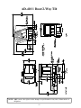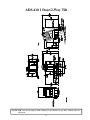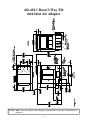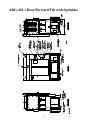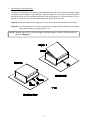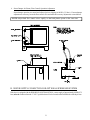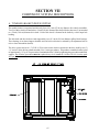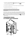
1
AD-410
(Phase 5)
Installation Manual
WARNING: For your safety the
information in this manual must be
followed to minimize the risk of fire or
explosion or to prevent property damage,
personal injury or death.
AVERTISSEMENT: Assurez-vous de bien
suivre les instructions données dans cette
notice pour réduire au minimum le risque
d’incendie ou d’explosion ou pour éviter tout
dommage matériel, toute blessure ou la mort.
Do not store or use gasoline or other flammable
vapor and liquids in the vicinity of this or any
other appliance.
Ne pas entreposer ni utiliser d’essence ni
d’autres vapeurs ou liquides inflammables dans
le voisinage de cet appareil ou de tout autre
appareil.
WHAT DO YOU DO IF YOU SMELL GAS
* Do not try to light any appliance.
* Do not touch any electrical switch; do not use
any phone in your building.
* Clear the room, building or area of all
occupants.
* Immediately call your gas supplier from a
neighbor's phone. Follow the gas supplier's
instructions.
* If you cannot reach your gas supplier, call the
fire department.
Installation and service must be performed by a
qualified installer, service agency or the gas
supplier.
QUE FAIRE SI VOUS SENTEZ UNE ODEUR
DE GAZ:
* Ne pas tenter d’allumer d’appareil.
* Ne touchez à aucun interrupteur. Ne pas
vous servir des téléphones se trouvant dans
le bâtiment où vous vous trouvez..
* Évacuez la pièce, le bâtiment ou la zone.
* Appelez immédiatement votre fournisseur de
gaz depuis un voisin. Suivez les instructions
du fournisseur.
* Si vous ne pouvez rejoindre le fournisseur
de gaz, appelez le service des incendies.
L’installation et l’entretien doivent être assurés
par un installateur ou un service d’entretien
qualifié ou par le fournisseur de gaz.
For replacement parts, contact the distributor from which the dryer
was purchased or
American Dryer Corporation
88 Currant Road
Fall River MA 02720-4781
Telephone: (508) 678-9000 / Fax: (508) 678-9447
e-mail: [email protected]
060597DMG/abe
ADC Part No. 112249
Retain This Manual In A Safe Place For Future Reference
American Dryer Corporation products embody advanced concepts in engineering, design, and safety. If this product is
properly maintained, it will provide many years of safe, efficient, and trouble-free operation.
ONLY qualified technicians should service this equipment.
OBSERVE ALL SAFETY PRECAUTIONS displayed on the equipment or specified in the installation manual included with
the dryer.
The following “FOR YOUR SAFETY” caution must be posted near the dryer in a prominent location.
FOR YOUR SAFETY
POUR VOTRE SÉCURITÉ
Do not store or use gasoline or
other flammable vapors or liquids
in the vicinity of this or any other
appliance.
Ne pas entreposer ni utiliser d’essence
ni d’autres vapeurs ou liquides
inflammables dans le voisinage de cet
appareil ou de yout autre appareil.
We have tried to make this manual as complete as possible and hope you will find it useful. ADC reserves the right to make
changes from time to time, without notice or obligation, in prices, specifications, colors, and material, and to change or
discontinue models.
Important
For your convenience, log the following information:
DATE OF PURCHASE ____________________________
AD-410
MODEL NO. __________________________________________
DISTRIBUTOR’S NAME ___________________________________________________________________________________
Serial Number(s)
________________________________________________________________________________________
________________________________________________________________________________________
________________________________________________________________________________________
Replacement parts can be obtained from your distributor or the ADC factory. When ordering replacement parts from the
factory, you can FAX your order to ADC at (508) 678-9447 or telephone your orders directly to the ADC Parts Department at
(508) 678-9000. Please specify the dryer model number and serial number in addition to the description and part number, so
that your order is processed accurately and promptly.
“IMPORTANT NOTE TO PURCHASER”
Information must be obtained from your local gas supplier on the instructions
to be followed if the user smells gas. These instructions must be posted in a
prominent location near the dryer.
IMPORTANT
YOU MUST DISCONNECT and LOCKOUT THE ELECTRIC SUPPLY and THE GAS
SUPPLY or THE STEAM SUPPLY BEFORE ANY COVERS or GUARDS ARE
REMOVED FROM THE MACHINE TO ALLOW ACCESS FOR CLEANING,
ADJUSTING, INSTALLATION, or TESTING OF ANY EQUIPMENT per OSHA
(Occupational Safety and Health Administration) STANDARDS.
“Caution: Label all wires prior to
disconnection when servicing controls. Wiring
errors can cause improper operation.”
«Attention: Lor des opérations d’entretien
des commandes étiqueter tous fils avant
de les déconnecter. Toute erreur de
câblage peut étre une source de danger et
de panne.»
CAUTION
DRYERS SHOULD NEVER BE LEFT UNATTENDED WHILE IN OPERATION.
WARNING
CHILDREN SHOULD NOT BE ALLOWED TO PLAY ON OR NEAR THE DRYERS.
CHILDREN SHOULD BE SUPERVISED IF NEAR DRYERS IN OPERATION.
FOR YOUR SAFETY
DO NOT DRY MOP HEADS IN THE DRYER.
DO NOT USE DRYER IN THE PRESENCE OF DRY CLEANING FUMES.
WARNING
UNDER NO CIRCUMSTANCES should the door switch or the heat circuit devices
ever be disabled.
WARNING
The dryer must never be operated with any of the back guards, outer tops, or service
panels removed. PERSONAL INJURY or FIRE COULD RESULT.
WARNING
DRYER MUST NEVER BE OPERATED WITHOUT THE LINT FILTER (SCREEN) IN
PLACE, EVEN IF AN EXTERNAL LINT COLLECTION SYSTEM IS USED.
IMPORTANT
PLEASE OBSERVE ALL SAFETY PRECAUTIONS displayed on the equipment or
specified in the installation manual included with the dryer.
Dryers must not be installed or stored in an area where it will be exposed to water or weather.
The wiring diagram for the dryer is located in the front electrical control box area.
Table of Contents
AD-410 REFERENCE GUIDE ........................................................................... 3
INTRODUCTION ................................................................................................ 5
AD-410 DRYER OPERATIONAL SUMMARY ............................................................................. 5
AD-410 OPERATOR CONTROLS/INDICATORS ........................................................................ 5
AD-410 DRYER OPERATION TROUBLESHOOTING INFORMATION .................................... 8
SECTION I
IMPORTANT INFORMATION ........................................................................ 16
A. Receiving and Handling ............................................................................................................. 16
B. Safety Precautions .................................................................................................................... 17
SECTION II
SPECIFICATIONS and DIMENSIONS ........................................................... 19
A. Specifications (Gas and Steam Models) .................................................................................... 19
B. Dimensions ............................................................................................................................... 20
SECTION III
INSTALLATION PROCEDURES .................................................................... 25
A.
B.
C.
D.
E.
F.
G.
H.
I.
J.
K.
Reassembly of Dryer ................................................................................................................ 25
Fresh Air Supply Requirements ................................................................................................. 32
Exhaust Requirements ............................................................................................................... 33
Compressed Air Supply System ................................................................................................ 35
Electrical Information ................................................................................................................ 38
Gas Information........................................................................................................................ 41
Steam Information .................................................................................................................... 45
Water Supply Connection For Optional Sprinkler System.......................................................... 49
Preoperational Tests ................................................................................................................. 50
Preparation For Operation/Start-Up ......................................................................................... 52
Shut Down Instructions ............................................................................................................. 53
SECTION IV
SERVICE/PARTS INFORMATION ................................................................. 54
A. Service ..................................................................................................................................... 54
B. Parts ........................................................................................................................................ 54
SECTION V
WARRANTY INFORMATION ......................................................................... 55
A. Returning Warranty Card(s) ...................................................................................................... 55
B. Warranty .................................................................................................................................. 55
C. Returning Warranty Part(s)........................................................................................................ 55
SECTION VI
ROUTINE MAINTENANCE ............................................................................ 57
A. Cleaning ................................................................................................................................... 57
B. Adjustments ............................................................................................................................. 59
C. Lubrication ............................................................................................................................... 59
SECTION VII
COMPONENT SYSTEM DESCRIPTIONS .................................................... 60
A.
B.
C.
D.
E.
F.
Tumbler (Basket) Drive System................................................................................................. 60
Tumbler (Basket) ...................................................................................................................... 61
Air Blower Drive System .......................................................................................................... 61
Air Jet System .......................................................................................................................... 61
Safety Devices.......................................................................................................................... 61
Steam Damper Actuator System ............................................................................................... 63
SECTION VIII
OPTIONAL SPRINKLER SYSTEM COMPONENTS ................................... 64
Optional Sprinkler Circuit Components ............................................................................................ 64
AD-410 Sprinkler Option Temperature Controller Settings ............................................................... 66
SECTION IX
TROUBLESHOOTING ..................................................................................... 67
SECTION X
PROCEDURE FOR FUNCTIONAL CHECK OF REPLACEMENT
COMPONENTS ................................................................................................ 75
SECTION XI
BURNER AND LINT (TUMBLER) CHAMBER MANUAL RESET
HI-LIMIT INSTRUCTIONS ............................................................................. 78
AD-410 Reference Guide
3
4
INTRODUCTION
AD-410 DRYER OPERATIONAL SUMMARY
The model AD-410 incorporates one (1) “EMERGENCY STOP” (E-Stop) BUTTON located centrally on the
right front control door. This “red” mushroom push-button is “PUSH TO STOP” the dryer and “TURN TO
RELEASE” or “PULL TO RELEASE” type control device. This button must be in the released mode to power
the dryer. The PHASE 5 MICROPROCESSOR CONTROLLER (computer) display will light when the
“EMERGENCY STOP” (E-Stop) BUTTON is in the released mode. To turn “ON” the AD-410’s control voltage,
press the “green” “ON” push-button located on the right front control door.
The AD-410 has two (2) electronic controllers:
PHASE 5 MICROPROCESSOR CONTROLLER (Computer) ... for drying material
MICRO-1 PLC (Programmable Logic Controller) ... for loading, unloading auto doors, and burner
status monitoring
The PHASE 5 MICROPROCESSOR CONTROLLER (Computer) only response to keyboard (touchpad)
commands when the AD-410’s tumbler (basket) section is level with the loading doors and lint drawer/basket door
closed. Likewise, the MICRO-1 PLC (Programmable Logic Controller) responses to load or unload selections
when the AD-410 is not drying material.
AD-410 OPERATOR CONTROLS/INDICATORS
The right front control door incorporates the following operator controls/indicators:
“EMERGENCY STOP” (E-Stop) BUTTON (Push To Stop/Turn To Release or Pull To Release)
JOG (Forward/Reverse Push-Buttons)
LOAD/DRY/UNLOAD (Three [3] Position Selector Switch)
TILT (Off - On) (Two [2] Position Selector Switch)
HEATER FAULT (Indicator/Reset Push-Button) Gas Models Only
CONTROL POWER (On)
CONTROL POWER (Off)
END OF CYCLE/HEATER FAULT INDICATOR/AIR JET
5
“EMERGENCY STOP” (E-Stop) BUTTON (Push To Stop/Turn To Release or Pull To Release)
This “red” mushroom push-button, located in the center of the right front control door almost directly under the
Phase 5 microprocessor controller (computer) is a “Push To Stop” and “Turn To Release” type push-button. This
button must be in the released mode to power the dryer (enable the dryer to run).
JOG (Forward/Reverse Push-Buttons)
These two (2) push-buttons, located towards the left hand side of the right front control door, are for either loading
or unloading the tumbler (basket). “JOG” functions are only enabled when the tumbler (basket) section is in a
tilted position.
NOTE: There is a PLC (Programmable Logic Controller) controlled “DWELL TIME” between
forward jog or reverse jog selection to prevent plug starting the tumbler (basket) drive
motor.
LOAD/DRY/UNLOAD (Three [3] Position Selector Switch)
TILT (Off - On) (Two [2] Position Selector Switch)
The “LOAD/DRY/UNLOAD” and “TILT (Off - On)” selector switches work in conjunction with each other. If
the “TILT” selector is in the “OFF” position, an “UNLOAD” or “LOAD” selection will open the front horizontal
doors, allowing an operator to load or unload the tumbler (basket) in the level position.
NOTE: The AD-410 “JOG” feature will respond in the level position. The lint drawer must be
closed for the “JOG” feature to operate.
If the “TILT” selector is in the “ON” position, an “UNLOAD” selection will open the front vertical doors and tilt
the tumbler (basket) section towards the front (Rear Up). Likewise, a “LOAD” selection will open the front
horizontal doors and tilt the tumbler (basket) section towards the rear (Front Up).
The “DRY” selection will bring the tumbler (basket) section to a level position and close the front horizontal
doors. Once ALL safe conditions are met (i.e., front doors closed, lint drawer closed, dryer level), an operator will
be able to select a drying cycle on the Phase 5 microprocessor controller’s (computer’s) keyboard (touchpad),
located on the right front control door. Refer to the Phase 5 Operator’s Manual for details.
HEATER FAULT (Indicator/Reset Button) Gas Models Only
During a drying cycle the PLC monitors the status of the Phase 5 microprocessor controller’s (computer’s) “Heat
On/Off” signal, the control status of the front and rear gas valves, and the state of both the front and rear burner
airflow switches. If a fault is sensed, the “HEATER FAULT” indicator and “END OF CYCLE” indicator will
begin to flash at a rate of one (1) per second. Both indicators will flash until the operator presses the “HEATER
FAULT” reset button. For more details on “HEATER FAULT” refer to the AD-410 operation section in this
manual.
6
CONTROL POWER (On)
This “green” lighted operator, located on the right front control door, is for enabling the dryer’s control voltage.
This push-button must be “ON” for drying or load/unload function to occur.
CONTROL POWER (Off)
This “red” non-lighted operator, located on the right front control door, is for disabling the dryer’s output control
voltage. This push-button is mainly for use as a troubleshooting function.
END OF CYCLE/HEATER FAULT INDICATOR/AIR JET
This “amber” colored indicator located on the front/top of the AD-410 has two (2) functions:
1. To indicate that a drying cycle has been completed and that the dried material is ready for attention. Once the
dryer is attended (i.e., lint drawer is opened or the “UNLOAD - DRY - LOAD” selector is turned to either the
“UNLOAD” or “LOAD” position and the vertical doors open) the indicator will go off.
2. To indicate that a “HEATER FAULT” has occurred. Note that during a “HEATER FAULT” this indicator
will flash in conjunction with the “HEATER FAULT Indicator/Reset Button” located on the right front
control door. Refer to the “HEATER FAULT Indicator/Reset Button” explanation on the previous page
(page 6), for more information concerning “HEATER FAULTS.”
3. The Air Jet will be activated at the end of the drying cycle when the “END OF CYCLE” light has been
energized. The Air Jet will remain active for approximately 30-seconds to remove lint which may have
accumulated on the Blower Wheel (squirrel cage).
7
AD-410 DRYER OPERATION TROUBLESHOOTING INFORMATION
END OF CYCLE/HEATER FAULT INDICATOR
The “END OF CYCLE” light located on the top/front of the AD-410, is triggered by the Air Jet Signal of the
Phase 5 microprocessor controller (computer) to the input of the PLC (Programmable Logic Controller). If this
signal is not sensed by the PLC the light will not turn on. The “1-second flashing” is accomplished by a “Flasher
Module” located on the main control panel in the right front control cabinet. Refer to the electrical blueprints
included with this dryer for detailed signal routing.
The “HEATER FAULT” signal is an output of the PLC to the “END OF CYCLE” light. A ‘HEATER FAULT”
is an indication that a malfunction has occurred in the “Gas Heat Circuit” and needs attention. Refer to the
“HEATER FAULT” explanations on page 10 and page 11 for more information on this subject.
If this “END OF CYCLE” light fails to display at the end of every cycle:
1. Check the bulb.
2. Check voltage to the bulb (24 VAC).
3. Refer to the ladder diagram and the schematics provided with this dryer for detailed signal information for
higher level troubleshooting.
JOG (Forward/Reverse Push-Button)
Forward “JOG” is in the clockwise (CW) direction and Reverse “JOG” is in the counterclockwise (CCW) direction.
There is a 7-second dwell (delay) time between a selection of a different rotation direction. This delay is to prevent
plug starting the tumbler (basket) drive motor.
If the “JOG” function does not operate in the tilted position:
1. Check that the main doors are fully opened.
2. Check that the overload for the drive motor is in the “Start” position.
3. Check that the overload for the tumbler (basket) motor is in the “Start” position.
4. Check that the lint drawer is closed.
5. Refer to the ladder diagram and the schematics provided with this dryer for detailed signal information for
higher level troubleshooting.
AIR JET
The Air Jet signal is sent from the Phase 5 microprocessor controller (computer) at the end of the drying cycle. If
the air valve fails to operate:
1. Check the air supply to the dryer (set to 80 PSI [5.51 bars]).
8
2. Check to see that the Air Jet L.E.D. (light emitting diode) is on at the end of the drying cycle. If the L.E.D.
is not on it may be an indication of a failed Phase 5 microprocessor controller (computer).
3. If Air Jet L.E.D. is on then check the wiring from the Phase 5 microprocessor controller (computer) to the air
valve.
4. Faulty air valve.
LOAD/DRY/UNLOAD (Selector Switch) and TILT FUNCTION (Off - On Selector Switch)
As mentioned in the dryer summary (refer to page 5), the “LOAD/DRY/UNLOAD” selector switch and “TILT
Off - On” selector switch work in conjunction with each other.
UNLOAD or LOAD LEVEL...opens the vertical doors only
If this selection does not operate:
1. Check that 80 PSI (5.51 bars) of compressed air is supplied to the dryer and that the door solenoid is being
actuated. The “Door Open” signal is generated by the PLC (Programmable Logic Controller). Refer to the
PLC information included in the ladder diagrams and schematics supplied with the dryer.
UNLOAD TILTED
This selection causes the front horizontal doors to open. Once the “Door Open” signal is sensed, the PLC enables
the “Rear Up” solenoid to tilt the dryer. Once the tumbler (basket) section releases the tilt switch, the “JOG”
functions become enabled for an operator’s selection.
If the tumbler (basket) section does not tilt forward:
1. Verify that a “Door Open” signal is being sensed by the PLC.
2. Check that 80 PSI (5.51 bars) of compressed air is supplied to the dryer and that the “Rear Up” solenoid is
being actuated by the PLC.
Refer to the PLC signal information included in the ladder diagrams and schematics supplied with the dryer.
LOAD TILTED
This selection causes the front horizontal doors to open. Once the “Door Open” signal is sensed, the PLC enables
the “Front Up” solenoid to tilt the dryer. The “JOG” functions then becomes enabled for an operator’s selection.
If the tumbler (basket) section does not tilt towards the rear:
1. Verify that a “Door Open” signal is being sensed by the PLC.
9
2. Check that 80 PSI (5.51 bars) of compressed air is supplied to the dryer and that the “Front Up” solenoid is
being actuated by the PLC (Programmable Logic Controller).
Refer to the PLC signal information included in the ladder diagrams and schematics supplied with the dryer.
DRY
This selection prepares the dryer for a “Material Drying Command” from the Phase 5 microprocessor controller
(computer).
NOTE: Before a drying cycle can be selected, the tumbler (basket) section must be in the level
position and both the front horizontal doors as well as the lint drawer must be closed.
The PLC senses that the dryer is level by the two (2) level switches located on the left hand side of the base section.
One (1) switch is towards the rear of the dryer and the other switch is towards the front of the dryer.
The PLC senses that the vertical doors are closed by the two (2) proximity switches, located at the top center of the
dryer above the doors. These switches are magnetically actuated by magnets located on the doors.
The PLC senses the lint drawer by a push type switch located on the right hand side of the lint drawer door.
IMPORTANT: THE LINT DRAWER and LINT DRAWER GUARD MUST BE CLOSED
BEFORE BRINGING THE DRYER TO A LEVEL POSITION.
If the tumbler (basket) section does not return to a level position:
1. Verify that a “Door Closed” signal is being sensed by the PLC.
2. Check that 80 PSI (5.51 bars) of compressed air is supplied to the dryer and that the “Front Down” or “Rear
Down” solenoid is being actuated by the PLC.
3. Verify that the lint drawer and lint drawer guard is in the closed position. This signal can be easily verified
since it is a PLC input.
Refer to the PLC signal information included in the ladder diagrams and schematics supplied with the dryer.
HEATER FAULT (Indicator/Reset Push-Button) Gas Dryers Only
“HEATER FAULT” refers to a problem in the gas heating portion of the dryer.
The PLC monitors the Phase 5 microprocessor controller’s (computer’s) Heat Off/On signals to the two (2)
individual gas valves that supply the two (2) separate burners.
When a “HEATER FAULT” occurs within the first 25-seconds of the drying cycle, the dryer will go to a “FILL”
message on the Phase 5 microprocessor controller’s (computer’s) display and both the “HEATER FAULT” pushbutton and the “END OF CYCLE” light will flash.
10
When a “HEATER FAULT” occurs after the first 25-seconds of the drying cycle, a “CLEAR/STOP” will be sent
to the Phase 5 microprocessor controller (computer), a “FILL” message will be displayed on the Phase 5
microprocessor controller’s (computer’s) display, and both the “HEATER FAULT” push-button and the “END
OF CYCLE” light will flash.
NOTE: If the “HEATER FAULT” reset push-button is pressed any time during the PLC
(Programmable Logic Controller) controlled cool down cycle, the dryer will come to a
stop since the dryer is being attended to by a qualified operator.
“HEATER FAULT” occurs during the following conditions:
Front and/or rear or both airflow switches are in the closed position at the start of a drying cycle.
IMPORTANT: At the start of a drying cycle, the tumbler (basket) will begin to turn and a few
seconds thereafter, the “FAN” signal will be asserted.
IF BOTH AIRFLOW SWITCHES ARE NOT OPEN AT THIS TIME THE
BLOWER WILL NOT START and A “HEATER FAULT” WILL OCCUR.
Both “HEATER FAULT” indicators will flash and the dryer will come to a
complete halt/stop until the “HEATER FAULT” push-button is pressed.
ONE or BOTH BURNERS DO NOT IGNITE
The model ADG-410 dryer has two (2) burner boxes. Each burner box has its own gas valve, Spark Ignitor/
Flame-Probe Assembly, and DSI (Direct Spark Ignition) module.
DSI (Direct Spark Ignition) MODULE
When the dryer calls for heat and ALL dryer safety switches are satisfied, a 24 VAC control signal is supplied to
both DSI modules. The DSI module L.E.D. (light emitting diode) indicators will light “red” for approximately
1.5-seconds of pre-purge, the L.E.D. indicators will light “green.” Each DSI module will energize its respective
gas valve and provide an 8-second spark to its Spark Ignitor/Flame-Probe Assembly. The gas in both burner
boxes should ignite. If ignition does not occur in one or both burners after 8-seconds, the flame will not be sensed
by the Spark Ignitor/Flame-Probe Assembly and the DSI module will go into the “LOCKOUT” mode lighting the
L.E.D. indicator(s) “red” continuously. THERE ARE NO IGNITION RETRIES BY THE DSI MODULE.
Stop the dryer at this point and restart another drying cycle. It may take several restarts to clear the gas supply
piping of air.
NOTE: “HEATER FAULT” will occur during the initial set up of the dryer, indicating that the
burners are not lighting due to air in the gas line.
GAS PRESSURE
The natural gas pressure supplied to the dryer must be between 6 inches (14.92 mb) and 12 inches of W.C. (water
column) - 29.9 mb - pressure. If the supply pressure is above 12 inches water column (29.9 mb) than an external
regulator must be installed to reduce the gas supply pressure to between 6 inches (14.92 mb) and 12 inches of
water column (29.9 mb).
11
Once the flame has been established in both burner boxes, the natural gas outlet manifold pressure measured at
each gas valve pressure tap must be 3.5 inches W.C. (water column) - 8.7 mb - pressure. Connect a water tube
manometer to the 1/8” F.P.T. gas pressure tap on the downstream side of each gas valve. There is a pressure
regulator in both gas valves so the manifold pressure can be adjusted to 3.5 inches water column (8.7 mb).
Unscrew the slotted regulator cover which is located on the top of each gas valve, and turn the regulator adjustment
screw located underneath the cover (clockwise [CW] to increase manifold pressure and counterclockwise [CCW]
to decrease manifold pressure).
The L.P. (liquid propane) gas pressure measured at each gas valve pressure tap must be 11 inches water column
(27.4 mb) pressure, when the flame is established in both burner boxes. There is no means to adjust this pressure
supplied with the dryer so the downstream L.P. pressure regulator must be adjusted to provide the 11 inch water
column (27.4 mb) outlet manifold pressure. Connect a water tube manometer to the 1/8” F.P.T. gas pressure tap
on the downstream side of each valve to measure the manifold pressure.
IMPORTANT INFORMATION
Once the blower motor starts, both the FRONT AIRFLOW SWITCH and the REAR AIRFLOW SWITCH
must pull in to indicate that there is sufficient airflow through the dryer for safe ignition of both the front
burner and the rear burner.
Refer to the system ladder diagram for “HEAT” signal information. There are several safety devices that must
be satisfied prior to ignition. Any one of these safety devices can cause NO IGNITION, therefore a “HEAT
FAULT”...i.e., FRONT AIRFLOW SWITCH
REAR AIRFLOW SWITCH
EXHAUST HI-LIMIT SWITCH
FRONT BURNER INTAKE HI-LIMIT SWITCH
REAR BURNER INTAKE HI-LIMIT SWITCH
DEFECTIVE ELECTRICAL HEAT CIRCUIT
12
ONE BURNER WILL NOT IGNITE AT THE BEGINNING OF A CYCLE
This condition can be caused by the following:
DEFECTIVE DSI (Direct Spark Ignition) MODULE
DEFECTIVE SPARK IGNITOR/FLAME-PROBE ASSEMBLY
DEFECTIVE GAS VALVE
INSUFFICIENT GAS PRESSURE
DEFECTIVE ELECTRICAL HEAT CIRCUIT
Refer to the ladder diagram and the schematics provided with this dryer for reference to the above listed
information.
ONE BURNER WILL NOT IGNITE DURING A DRYING CYCLE
This condition can be caused by the following:
DEFECTIVE DSI (Direct Spark Ignition) MODULE
DEFECTIVE SPARK IGNITOR/FLAME-PROBE ASSEMBLY
DEFECTIVE GAS VALVE
DEFECTIVE ELECTRICAL HEAT CIRCUIT
LOSS OF GAS PRESSURE
Refer to the ladder diagram and the schematics provided with this dryer for reference to the above listed
information.
CONTROL POWER (Indicator/Control Power On Push-Button)
This “green” lighted push-button is for enabling the 24 VAC control voltage to the control circuits of the dryer.
This push-button indicator must be “ON” for the system to load or dry material.
Refer to the ladder diagram included with this AD-410 for the function of this push-button in the 24 VAC control
voltage latching control circuit.
CONTROL POWER (Off Push-Button)
This “red” non-lighted push-button is for disabling the 24 VAC control voltage to the control circuits of the dryer.
Refer to the ladder diagram included with this AD-410 for the function of this push-button in the 24 VAC control
voltage latching control circuit.
SYSTEM LADDER DIAGRAM
The SYSTEM LADDER DIAGRAM is an overview on the electrical connections of the AD-410. This diagram
is for signal flow information and is a tool to direct an individual in the correct direction for troubleshooting this
dryer.
13
The AD-410 system is divided into a number of “electrical” sections which are as follows:
1. Right Front Control Panel
The RIGHT FRONT CONTROL PANEL is located in the right front control cabinet of the AD-410. This
panel is the heart of the drying system, where ALL control signals interface to or from this panel. The
signals that interface to this panel are too many to list here, however, they are ALL identified on TB1 of its
schematic diagram.
2. Right Base Electrical Enclosure
The RIGHT BASE ELECTRICAL ENCLOSURE is located towards the front of the right base section. An
industrial multi-pin connector is used to connect the base section control signals to the tumbler (basket)
section’s main control panel. This electrical enclosure is labeled CAUTION, HIGH VOLTAGE IS
PRESENT IN THIS ENCLOSURE and incorporates the following electrical devices:
The MAIN ELECTRICAL POWER to the dryer
The ELECTRICAL CONNECTION for the “OPTIONAL” SPRINKLER CIRCUIT POWER
The THERMAL/MAGNETIC OVERLOAD and REVERSING CONTACTOR for the TUMBLER
(BASKET) MOTOR
The THERMAL/MAGNETIC OVERLOAD and REVERSING CONTACTOR for the BLOWER
MOTOR
3. Right Base Interface Junction Box
The RIGHT BASE INTERFACE JUNCTION BOX is located towards the rear of the right base section and
is used as a central location to interface the base section electrical components to the TILTING tumbler
(basket) section. An industrial multi-pin connector is used to connect the base section control signals to the
tumbler (basket) section’s main control panel. The control signals incorporated in the right base interface
junction box are:
SOLENOID CONTROL
Front Up/Front Down
Rear Up/Rear Down
Open Front Door
Supply Air Enable
Air Jet
LINT DRAWER/GUARD STATUS
TUMBLER (BASKET) TEMPERATURE and HI-LIMIT INFORMATION
TUMBLER (BASKET) LEVEL SENSE
Front Level Switch
Rear Level Switch
OPTIONAL SPRINKLER CONTROL SIGNALS
14
4. Optional Sprinkler Circuit
The OPTIONAL SPRINKLER CIRCUIT main control panel will be located in the left front electrical
enclosure. If a SPRINKLER OPTION is included with this AD-410, this panel will include an “AUTOMATIC
‘EMERGENCY STOP’ (E-Stop)” feature. This feature requires the Sprinkler Circuit be functional for the
dryer to be powered.
NOTE: There will be a dedicated electrical connection in the right electrical junction box for the
sprinkler circuit.
15
SECTION I
IMPORTANT INFORMATION
A. RECEIVING and HANDLING
The dryer is shipped in a protective stretch wrap cover with protective cardboard corners and top cover (or
optional box) as a means of preventing damage in transit. Upon delivery, the dryer and/or packaging, and wooden
skid should be visually inspected for shipping damage. If any damage whatsoever is noticed, inspect further
before delivering carrier leaves.
Dryers damaged in shipment:
1. ALL dryers should be inspected upon receipt and before they are signed for.
2. If there is suspected damage or actual damage, the trucker’s receipt should be so noted.
3. If the dryer is damaged beyond repair, it should be refused. Those dryers which were not damaged in a
damaged shipment should be accepted, but the number received and the number refused must be noted on
the receipt.
4. If you determine that the dryer was damaged after the trucker has left your location, you should call the
delivering carrier’s freight terminal immediately and file a claim. The freight company considers this concealed
damage. This type of freight claim is very difficult to get paid and becomes extremely difficult when more
than a day or two passes after the freight was delivered. It is your responsibility to file freight claims. Dryer/
parts damaged in transit cannot be claimed under warranty.
5. Freight claims are the responsibility of the consignee, and ALL claims must be filed at the receiving end.
ADC assumes no responsibility for freight claims or damages.
6. If you need assistance in handling the situation, please contact the ADC Traffic Manager at (508)
678-9000.
IMPORTANT: The dryer must be transported and handled in an upright position at ALL times.
16
B. SAFETY PRECAUTIONS
WARNING: For your safety, the information in this manual must be followed to minimize the
risk of fire or explosion or to prevent property damage, personal injury, or loss of
life.
WARNING: The dryer must never be operated with any of the back guards, outer tops, or
service panels removed. PERSONAL INJURY or FIRE COULD RESULT.
1. DO NOT store or use gasoline or other flammable vapors and liquids in the vicinity of this or any other
appliance.
2. Purchaser/user should consult the local gas supplier for proper instructions to be followed in the event the
user smells gas. The instructions should be posted in a prominent location.
3. WHAT TO DO IF YOU SMELL GAS...
a. DO NOT try to light any appliance.
b. DO NOT touch any electrical switch.
c. DO NOT use any phone in your building.
d. Clear the room, building, or area of ALL occupants.
e. Immediately call your gas supplier from a neighbor’s phone. Follow the gas supplier’s instructions.
f. If you cannot reach your gas supplier, call the fire department.
4. Installation and service must be performed by a qualified installer, service agency, or gas supplier.
5. Dryer(s) must be exhausted to the outdoors.
6. Although ADC produces a very versatile dryer, there are some articles that, due to fabric composition or
cleaning method, should not be dried in it.
WARNING: Dry only water-washed fabrics. DO NOT dry articles spotted or washed in dry
cleaning solvents, a combustible detergent, or “all purpose” cleaner.
EXPLOSION COULD RESULT.
WARNING: DO NOT dry rags or articles coated or contaminated with gasoline, kerosene, oil,
paint, or wax.
EXPLOSION COULD RESULT.
WARNING: DO NOT dry mop heads. Contamination by wax or flammable solvents will create
a fire hazard.
WARNING: DO NOT use heat for drying articles that contain plastic, foam, sponge rubber, or
similarly textured rubberlike materials. Drying in a heated tumbler (basket) may
damage plastics or rubber and also may be a fire hazard.
17
7. A program should be established for the inspection and cleaning of lint in the burner area, exhaust duct
work, and area around the back of the dryer. The frequency of inspection and cleaning can best be determined
from experience at each location.
WARNING: The collection of lint in the burner area and exhaust duct work can create a
potential fire hazard.
8. For personal safety, the dryer must be electrically grounded in accordance with local codes and/or the
National Electrical Code ANSI/NFPA NO. 70-LATEST EDITION or in Canada, the Canadian Electrical
Codes Parts 1 & 2 CSA C22.1-1990 or LATEST EDITION.
NOTE: Failure to do so will VOID THE WARRANTY.
9. UNDER NO CIRCUMSTANCES should the dryer door switches, lint drawer switch, heat safety circuit,
or tilt switches ever be disabled.
WARNING: PERSONAL INJURY or FIRE COULD RESULT.
10. This dryer is not to be used in the presence of dry cleaning solvents or fumes.
11. Remove articles from the dryer as soon as the drying cycle has been completed.
WARNING: Articles left in the dryer after the drying and cooling cycles have been completed
can create a fire hazard.
12. READ and FOLLOW ALL CAUTION and DIRECTION LABELS ATTACHED TO THE DRYER.
WARNING: YOU MUST DISCONNECT and LOCKOUT THE ELECTRIC SUPPLY and
THE GAS SUPPLY or THE STEAM SUPPLY BEFORE ANY COVERS or
GUARDS ARE REMOVED FROM THE DRYER TO ALLOW ACCESS
FOR CLEANING, ADJUSTING, INSTALLATION, or TESTING OF ANY
EQUIPMENT per OSHA (Occupational Safety and Health Administration)
STANDARDS.
18
SECTION II
SPECIFICATIONS and DIMENSIONS
A. SPECIFICATIONS (Gas and Steam Models)
Maximum Capacity (Dry Weight)
410 lbs.
185.97 kg
Minimum Capacity (Dry Weight)
250 lbs.
113.40 kg
Tumbler (Basket) Diameter
68-3/4”
174.6 cm
Tumbler (Basket) Depth
66-3/8”
168.6 cm
Tumbler (Basket) Volume
143 cu. ft.
4.05 cu.m.
Drive Motor
7-1/2 HP
5.59 kw
25 HP
18.64 kw
40” Wide x 50” High
101.6 cm x 127 cm
Door Still Height - Level
39-3/4”
100.97 cm
Compressed Air
80 PSI
5.51 bars
3/8” F.P.T.
---
Blower Motor (Gas/Steam)
Door Opening
Compressed Air Connection
Gas*
Voltage Available
208-460v 3ø 3, 4w 50/60 Hz
Heat Input
1,600,000 btu/hr
403,200 kcal/hr
Approx. Weight (Uncrated)
7,500 lbs.
3,401.94 kg
Airflow
9,200 cfm
260.52 cmm
Inlet Pipe Size
2” F.P.T.
---
Voltage Available
208-460v 3ø 3, 4w 50/60 Hz
Steam*
Approx. Weight (Uncrated)
Airflow
12,000 cfm
339.80 cmm
823.27 kg/hr
55
Operating Steam Pressure
125 PSI max
3,628.74 kg
Boiler HP
Normal Load
Steam Consumption
1,815 lbs/hr
8,000 lbs.
Steam Supply
8.79 kg/sq cm
2”
5.08 cm
Steam Return
1-1/4”
3.18 cm
Shaded areas are stated in metric equivalents
* Dryers must be provided with a clean, dry, regulated 80 PSI +/- 10 PSI (5.51 bars +/- 0.68 bars) air supply
(equivalent volume = 9 cfh [0.26 cmh]).
NOTE: ADC reserves the right to make changes in specifications at any time, without notice or
obligation.
19
B. DIMENSIONS
ADS-410
ADG-410
AD-410 TILTING CLEARANCE A LLOW ANCES
1 DOOR/FORWARD TILT
130-1/4”
330.84 cm
1 DOOR/2-WAY TILT
137-1/4”
348.62 cm
2 DOOR/REAR TILT
137-1/4”
348.62 cm
1 DOOR/FORWARD TILT
138-15/16”
352.90 cm
1 DOOR/2-WAY TILT
138-15/16”
352.90 cm
2 DOOR/2-WAY TILT
138-15/16”
352.90 cm
Shaded areas are stated in metric equivalents
WARNING: Dryer should be located where a minimum length of exhaust duct will be
necessary.
20
AD-410 1 Door/2-Way Tilt
NOTE: ADC reserves the right to make changes in specifications at any time, without notice or
obligation.
21
AD-410 1 Door/2-Way Tilt
NOTE: ADC reserves the right to make changes in specifications at any time, without notice or
obligation.
22
ADS-410 1 Door/2-Way Tilt
NOTE: ADC reserves the right to make changes in specifications at any time, without notice or
obligation.
23
AD-410 1 Door/2-Way Tilt
with Inlet Air Adapter
NOTE: ADC reserves the right to make changes in specifications at any time, without notice or
obligation.
24
SECTION III
INSTALLATION PROCEDURES
Installation in a proper location should be performed by competent technicians in accordance with local and state
codes. In the absence of these codes, the installation must conform to applicable American National Standards:
National Fuel Gas Code ANSI.Z223.1-LATEST EDITION and/or National Electrical Code ANSI/NFPA NO.
70-LATEST EDITION, or in Canada, the Canadian Electrical Codes Parts 1 & 2 CSA C22.1-1990 or LATEST
EDITION.
Before installing the dryer, be sure the location conforms to local codes and ordinances.
The dryer must be installed on a sound level floor capable of supporting its weight. Carpeting must be removed
from the floor area that the dryer is to rest on.
IMPORTANT: “The dryer must be installed on noncombustible floors only.”
IMPORTANT: Dryer should be located where a minimum amount of exhaust duct will be
necessary.
A. REASSEMBLY OF DRYER
IMPORTANT: Always keep the tumbler (basket) section in an upright position when moving
and/or transporting.
The AD-410 dryer is shipped in two (2) pieces with the tumbler (basket) section separate from the base section.
The tumbler (basket) section will have to be lifted/hoisted onto the base section. Use cables through the eye bolts
on top of the tumbler (basket) section, or use a forklift for the lifting process.
The AD-410 tilting dryer is made with many loading and unloading options. Please refer to the reassembly
instructions on the following pages for your particular style of dryer.
If a steam dryer is shipped in two (2) pieces, the steam coil may have been removed from the top of the tumbler
(basket) section and shipped with the base section. If this is the case, carefully lift the steam coil on to the top of
the tumbler (basket) section with the steam pipe connections facing towards the right hand side of the dryer and
bolt the coil to the top of the dryer with the 1/4” (6.35 mm) hardware supplied. There are three (3) panels that
cover the front, right hand side, and rear of the steam coil. Fasten these into position also. Reconnect the steam
pipe and condensate pipe unions to the coil. These pipes run down to the flex hoses in the base section.
25
ADG-410 1 Door/Forward Tilt with Sprinkler
26
1. Reassembly for the ADG-410 1 Door/Forward Tilt with Sprinkler Gas Model Dryer ...
Lift the tumbler (basket) section onto the base ...
a. Forward tilting dryers have two (2) tilting pistons located in the rear corners of the dryer base and two (2)
piston posts located in the front corners of the dryer base. On the top of the tilting pistons and tilting
posts are clevis blocks. Use the eight (8) 1/2 x 1-1/4” hex head bolts and lock washers (supplied with the
dryer) to secure each clevis block to the bottom of the tumbler (basket) section.
Refer to Tilting Piston Reconnection View on page 28.
Refer to Tilting Post Reconnection View on page 28.
b. The gas line is disconnected at the union when the dryer is shipped in two (2) pieces. This gas line union
is located in the right hand side of the dryer base. Insert the gas line union half way through the hole on
the bottom of the tumbler (basket) section. Connect the two (2) union halves and retighten.
IMPORTANT: THE FLEX HOSE MUST NOT BE KINKED.
Refer to Gas Flex Hose Union Reconnection View on page 28.
c. There are five (5) electrical reconnections ...
1) Four (4) of these electrical connections are located in the right hand side of the dryer base. The four
(4) mating sockets are located in the right hand side of the tumbler (basket) section and must be
reconnected with the four (4) mating sockets in the dryer base.
2) The remaining electrical connection is made at the drive motor located in the right hand side of the
tumbler (basket) section.
IMPORTANT: THE RECONNECTED ELECTRICAL CABLES MUST HAVE ENOUGH
SLACK IN THEM TO ALLOW THE DRYER TO TILT FREELY IN BOTH
DIRECTIONS.
d. Reattach The Tilt Guard Panel ...
1) Use the 1/4-20 x 3/8” hex head bolts and lock washers (supplied with the dryer) to secure the top of
the front tilt guard into the bottom of the front of the tumbler (basket) section.
2) Use the 1/4-20 x 3/8” hex head bolts and lock washers (supplied with the dryer) to secure the top of
the rear tilt guard into the bottom of the rear of the tumbler (basket) section.
3) Use the 1/4-20 self-tapping screws (supplied with the dryer) to secure the right hand side tilt guards
and left hand side tilt guards.
4) Reconnect the spring and claw assembly which connects the rear tilt guard to each side tilt guard.
5) Reconnect both chains to the back panel...the spring keeps the rear guard close to the dryer’s back as
the dryer is tilted forward or backwards. (Refer to Tilt Guard Reconnection View on page 28.)
27
e. Secure the 28-inch (71.12 cm) diameter exhaust duct transition piece to the dryer’s rectangular exhaust
duct with the 1/4-20 self-tapping screws (supplied with the dryer).
The exhaust duct exits from the rear of the base.
f. On dryers equipped with automatic (piston operated) load doors, reconnect the two (2) poly-flo air lines
that run from the dryer base up to the door pistons.
g. On dryers equipped with a sprinkler option, a separate power supply must be connected to the sprinkler
circuit located in the right base electrical box.
1) The optional sprinkler water connection is located in the left hand side of the dryer base. A 1-inch M.P.T.
water supply line will be connected to the 1-inch F.P.T. pipe connection of the dryer.
ADG-410 1 Door/Forward Tilt
with Sprinkler
TILTING PISTON RECONNECTION VIEW
TILTING POST RECONNECTION VIEW
MAN3507
MAN2771
TILT GUARD RECONNECTION VIEW
GAS FLEX HOSE UNION RECONNECTION VIEW
MAN2247
MAN3506
28
ADS-410 2 Door/2-Way Tilt
29
1. Reassembly for the ADS-410 2 Door/2-Way Tilt Steam Model Dryer ...
Lift the tumbler (basket) section onto the base ...
a. 2-way tilting dryers have four (4) tilting pistons, one (1) located in each corner of the dryer base. On the
top of each tilting piston is a clevis block. Use the four (4) 1/2 x 1-1/4” hex head bolts and lock washers
(supplied with the dryer) to secure each clevis block to the bottom of the tumbler (basket) section.
Refer to Tilting Piston Reconnection View on page 31.
b. Both the 2-inch (5.08 cm) steam supply line and the 1-1/4” (3.18 cm) condensate return line unions are
disconnected when the dryer is shipped in two (2) pieces. The steam supply lines are located in the right
hand side of the dryer base. Insert both union halves up through the holes in the bottom of the tumbler
(basket) section. Connect the two (2) union halves and retighten.
IMPORTANT: THE FLEX HOSE MUST NOT BE KINKED.
Refer to Steam Flex Hose Union Reconnection View on page 31.
c. The air lines are disconnected when the dryer is shipped in two (2) pieces. The air lines are located in the
right hand side of the dryer base. Insert the air lines through the hole on the bottom of the tumbler
(basket) section. Reconnect the 1/4” (6.35 mm) brass poly connector.
d. There are four (4) electrical reconnections ...
1) The plug and cable connections are located in the right hand side of the dryer base. These must be
lifted up and reconnected into the mating sockets located at the bottom right hand side of the tumbler
(basket) section.
2) The drive motor power cable must be lifted up and reconnected into the drive motor in the right hand
side of the tumbler (basket) section.
IMPORTANT: THE RECONNECTED ELECTRICAL CABLES MUST HAVE ENOUGH
SLACK IN THEM TO ALLOW THE DRYER TO TILT FREELY IN BOTH
DIRECTIONS.
e. Reattach The Tilt Guard Panel ...
1) Use the 1/4-20 x 3/8” hex head bolts and lock washers (supplied with the dryer) to secure the top of
the front tilt guard into the bottom of the front of the tumbler (basket) section.
2) Use the 1/4-20 x 3/8” hex head bolts and lock washers (supplied with the dryer) to secure the top of
the rear tilt guard into the bottom of the rear of the tumbler (basket) section.
3) Use the 1/4-20 self-tapping screws (supplied with the dryer) to secure the right hand side tilt guards
and left hand side tilt guards.
Refer to Tilting Guard Panel Reconnection View on page 31.
30
f. Secure the 28-inch (71.12 cm) diameter exhaust duct transition piece to the dryer’s rectangular exhaust
duct with the 1/4-20 self-tapping screws (supplied with the dryer).
The exhaust duct exits from the rear of the base.
g. On dryers equipped with automatic (piston operated) load doors, reconnect the four (4) poly-flo air lines
that run from the dryer base up to the door pistons in the front and the rear of the dryer.
h. Reconnect the 1/4” (6.35 mm) poly-flo air lines which run from the dryer base up to the steam damper
solenoid valve (located on top of the dryer).
ADS-410 2 Door/2-Way Tilt
TILTING PISTON RECONNECTION VIEW
STEAM FLEX HOSE UNION RECONNECTION VIEW
MAN3507
TILTING GUARD PANEL RECONNECTION VIEW
MAN3587
31
B. FRESH AIR SUPPLY REQUIREMENTS
When the dryer is operating, it draws in room air, heats it, passes this air through the tumbler (basket) and
exhausts it out of the building. Therefore, the room air must be continually replenished from the outdoors. If
the make-up air is inadequate, drying time and efficiency will be adversely affected. Ignition problems and sail
switch “fluttering” problems may result, as well as premature motor failure from overheating.
Air supply (make-up air) must be given careful consideration to assure proper performance of each dryer. An
unrestricted source of air is necessary for each dryer. An airflow of 9,200 cfm (cubic feet per minute) - 260.52
cmm (cubic meters per minute) - must be supplied to each gas dryer and 12,000 cfm (339.80 cmm) must be
supplied to each steam dryer. As a general rule, an unrestricted air entrance from the outdoors (atmosphere) of a
minimum of 12 square feet (1.11 square meters) is required for each gas dryer and a minimum of 14 square feet
(1.30 square meters) is required for each steam dryer.
To compensate for the use of registers or louvers used over the openings, this make-up air area must be increased
by approximately thirty-three percent (33%). Make-up air openings should not be located in an area directly near
where exhaust vents exit the building.
It is not necessary to have a separate make-up air opening for each dryer. Common make-up air openings are
acceptable. However, they must be set up in such a manner that the make-up air is distributed equally to ALL
the dryers.
Allowances must be made for remote or constricting passageways or where dryers are located at excessive
altitudes or predominantly low pressure areas.
IMPORTANT: Make-up air must be provided from a source free of dry cleaning solvent fumes.
Make-up air that is contaminated by dry cleaning solvent fumes will result in
irreparable damage to the motors and other dryer components.
NOTE: Component failure due to dry cleaning solvent fumes will VOID THE WARRANTY.
1. Optional Inlet Air Adapter
The ADG-410 dryer may be built with the inlet air adapter option. This option allows ALL of the dryer’s
inlet air to be ducted from the outdoors directly to the dryer.
This option consists of a sheet metal box located on top of the dryer with two (2) 30-inch (76.2 cm)
diameter duct collars on top. (Refer to the illustration on page 24 for the location and dimensions of the inlet
air adapter.)
Use two (2) 30-inch (76.2 cm) diameter flexible hoses to connect the 30-inch (76.2 cm) collars to the
outdoors. Allow enough slack in the flexible hoses so that the dryer can tilt, without restriction.
32
C. EXHAUST REQUIREMENTS
NOTE: For 1 door AD-410 dryer models, the 28-inch (71.12 cm) diameter exhaust duct exits
from the rear of the base. For 2 door AD-410 dryer models, the 28-inch (71.12 cm)
diameter exhaust duct exits from the left hand side of the base.
NOTE: For 1 door/2-way tilt AD-410 dryer models, keep the exhaust ducting at least 36-inches
(91.44 cm) away from the back of the dryer so that the dryer will not hit the ducting
when the dryer tilts to the rear.
1. General Exhaust Duct Work Information
a. Gas Models
Exhaust duct work should be designed and installed by a qualified professional. Improperly sized duct
work will create excessive back pressure which results in slow drying, increased use of energy, overheating
of the dryer, and shut down of the burner by the airflow (sail) switches, burner hi-limits, or tumbler
(basket) hi-heat thermostats.
CAUTION: DRYER MUST BE EXHAUSTED TO THE OUTDOORS.
CAUTION: IMPROPERLY SIZED or INSTALLED EXHAUST DUCT WORK CAN
CREATE A POTENTIAL FIRE HAZARD.
NOTE: When a dryer is exhausted separately, it is recommended that a back draft damper be
installed.
1) Horizontal Venting
The duct work should be laid out in such a way that the duct work travels as directly as possible to
the outdoors with as few turns as possible. Single or independent dryer venting is recommended.
The shape of the duct work is not critical so long as the minimum cross-sectional area is provided. It
is suggested that the use of 90º turns in ducting be avoided; use 30º and/or 45º angles instead. The
radius of the elbows should preferably be 1-1/2 times the diameter of the duct.
The dryer comes with a 28-inch (71.12 cm) diameter exhaust duct connection. The plant’s exhaust
duct must be at least 28-inches (71.12 cm) in diameter or for a rectangular duct have a crosssectional area of 616 square inches (3,974 square centimeters). The duct work from the dryer to the
outside exhaust outlet should not exceed 20 feet (6.09 meters). The shape of the duct work is not
critical so long as the minimum cross-sectional area is provided. It is suggested that the use of 90º
turns be avoided; use 45º angles instead. The radius of the elbows should preferably be 1-1/2 times
the width or diameter of the duct. Excluding tumbler (basket)/dryer elbow connections or elbows
used for outside protection from the weather, no more than one (1) elbow should be used in the
exhaust duct run. If more than one (1) elbow is used, the cross-sectional area of the duct work must
be increased.
IMPORTANT: Minimum duct size for a horizontal run must be 28-inches (71.12 cm) for a
round or 25” x 26” (63.5 cm x 66.04 cm) for a square duct. Duct size must not
be reduced anywhere downstream of the dryer.
33
2) Vertical Venting
IMPORTANT: Minimum duct size for a vertical run must be 32-inches (81.28 cm) for a round
or 30” x 28” (76.2 cm x 71.12 cm) for a square duct. Duct size must not be
reduced anywhere downstream of the dryer.
THE AD-410 MUST BE INDEPENDENTLY EXHAUSTED. COMMON DUCT WORK IS
NOT ACCEPTABLE. The exhaust duct should be laid out in such a way that the duct work travels
as directly as possible to the outdoors with as few turns as possible. It is suggested that the use of 90°
turns in ducting be avoided; use 30° and/or 45° angles instead. The shape of the exhaust duct work
is not critical so long as the minimum cross section area is provided.
IMPORTANT: Minimum duct size for a vertical run must be 32-inches (81.28 cm) for a round
or 30” x 28” (76.2 cm x 71.12 cm) for a square duct. Duct size must not be
reduced anywhere downstream of the dryer.
IMPORTANT: Exhaust back pressure measured by a manometer at each tumbler (basket)
exhaust duct area should not exceed 0.3 inches of water column (0.74 mb).
It is suggested that the duct work from each dryer not exceed 20 feet (6.09 meters) with no more than
two (2) elbows (excluding dryer connections and outside exhaust outlets). If the duct work exceeds
20 feet (6.09 meters) or has numerous elbows, the cross section area of the duct work must be
increased in proportion to the length and number of elbows in it. In calculating duct size, the cross
section area of a square or rectangular duct must be increased by twenty percent (20%) for each
additional 20 feet (6.09 meters). The diameter of a round exhaust duct should be increased ten
percent (10%) for each additional 15 feet (4.57 meters). Each 90º elbow is equivalent to an additional
80 feet (24.38 meters), and each 45° elbow is equivalent to an additional 40 feet (12.19 meters).
34
b. Steam Models
1) Horizontal Venting
THE AD-410 MUST BE INDEPENDENTLY EXHAUSTED. COMMON DUCT WORK IS
NOT ACCEPTABLE. The exhaust duct should be laid out in such a way that the duct work travels
as directly as possible to the outdoors with as few turns as possible. It is suggested that the use of 90°
turns in ducting be avoided; use 30° and/or 45° angles instead. The shape of the exhaust duct work
is not critical so long as the minimum cross section area is provided.
IMPORTANT: Minimum duct size for the dryer is 28-inches (71.12 cm) for a round duct or
25” x 26” (63.5 cm x 66.04 cm) for a square duct. Duct size must not be
reduced anywhere downstream of the dryer.
IMPORTANT: Exhaust back pressure measured by a manometer at each tumbler (basket)
exhaust duct area should not exceed 0.3 inches of water column (0.74 mb).
It is suggested that the duct work from each dryer not exceed 20 feet (6.09 meters) with no more than
one (1) elbow (excluding dryer connections and outside exhaust outlets). If the duct work exceeds 20
feet (6.09 meters) or has numerous elbows, the cross section area of the duct work must be increased
in proportion to the length and number of elbows in it. In calculating duct size, the cross section area
of a square or rectangular duct must be increased by twenty percent (20%) for each additional 20
feet (6.09 meters). The diameter of a round exhaust duct should be increased ten percent (10%) for
each additional 15 feet (4.57 meters). Each 90º elbow is equivalent to an additional 68 feet (20.73
meters), and each 45° elbow is equivalent to an additional 34 feet (10.36 meters).
2) Vertical Venting
IMPORTANT: Minimum duct size for the dryer is 36-inches (91.44 cm) for a round duct or
34” x 32” (86.36 cm x 81.28 cm) for a square duct. Duct size must not be
reduced anywhere downstream of the dryer.
It is suggested that the duct work from each dryer not exceed 20 feet (6.09 meters) with no more than
two (2) elbows (excluding dryer connections and outside exhaust outlets). If the duct work exceeds
20 feet (6.09 meters) or has numerous elbows, the cross section area of the duct work must be
increased in proportion to the length and number of elbows in it. In calculating duct size, the cross
section area of a square or rectangular duct must be increased by twenty percent (20%) for each
additional 20 feet (6.09 meters). The diameter of a round exhaust duct should be increased ten
percent (10%) for each additional 15 feet (4.57 meters). Each 90º elbow is equivalent to an additional
93 feet (28.35 meters), and each 45° elbow is equivalent to an additional 46-1/2 feet (14.17 meters).
35
ALL duct work should be smooth inside with no projections from sheet metal screws or other
obstructions which will collect lint. When adding ducts, the duct to be added should overlap the duct
to which it is to be connected. ALL duct work joints must be taped to prevent moisture and lint from
escaping into the building. Inspection doors should be installed at strategic points in the exhaust
duct work for periodic inspection and clean-out of lint from the duct work.
IMPORTANT: Exhaust back pressure measured by a Magnehelic in the exhaust duct should not
exceed 0.3 inches of water column (0.74 mb).
NOTE: When the exhaust duct work passes through a wall, ceiling, or roof made of combustible
materials, the opening must be 2-inches (5.08 cm) larger than the duct (ALL the way
around). The duct must be centered within this opening.
a) Outside Duct Work Protection
(1) To protect the outside end of horizontal duct work from the weather, a 90º elbow turned
downward should be installed where the exhaust exits the building. If the duct work travels
vertically up through the roof, it should be protected from the weather by using a 180º turn
to point the opening downward. In either case, allow at least twice the diameter of the duct
between the duct opening and the nearest obstruction.
IMPORTANT: DO NOT use screens or caps on the outside opening of the exhaust duct work.
36
D. COMPRESSED AIR SUPPLY SYSTEM
The compressed air system of the AD-410 tilting dryer consists of a number of pneumatic pistons located throughout
the dryer. The pneumatics are actuated by solenoid and flow control valves that are under computer control. The
pneumatic pistons are used to:
• Tilt the Dryer For Loading and Unloading
• Open and Close the Load and Unload Doors (for AD-410 dryer models equipped with Automatic Doors)
• Operate the Steam Coil Damper (for ADS-410 Steam Heated Models ONLY)
• Air Jet is used to clean lint from the blower fan (impellor)
1. Filter/Regulator Assembly
The compressed air supply to the dryer is connected into the 3/8” F.P.T. fitting of the filter/regulator assembly
which is located at the bottom rear of the right hand side of the base.
The filter/regulator assembly performs two (2) essential functions. The filter removes most solids and
liquid particles from the compressed air stream and traps them in its bowl where this waste can be readily
removed through the drain valve at the bottom of the bowl.
The filter bowl should be cleaned monthly.
The regulator will maintain a nearly constant outlet air pressure so that the dryer’s pneumatics will function
normally despite upstream air pressure variations. After the compressed air is connected into the filter/
regulator assembly, adjust the regulator knob so that the gauge needle reads 80 PSI (5.51 bars).
2. Tilting-Piston Solenoid Valves
A 2-way tilt dryer has two (2) pairs of these solenoid valves...one to control the front set of tilting pistons and
a second to control the rear set of tilting pistons. A 1-way tilt dryer has only one (1) pair of solenoid valves.
37
Each valve has five (5) 3/8” F.P.T. ports and two (2) electric solenoid operators, one (1) on each side of the
valve.
To tilt the dryer forward, a 24 volt signal is applied to the rear pistons solenoid connector “12” and no voltage
is applied to the solenoid connector “14.” The internal spool in the valve will move and 80 PSI (5.51 bars)
of air will enter the bottom port of the rear tilting pistons, extending the rear tilting piston rods and tilting the
dryer forward for unloading. The top piston ports are bled to the atmosphere.
To level the dryer, the voltage signals are reversed. No voltage is applied to the “12” solenoid, and 24 volts
is applied to the “14” solenoid. The valve spool will now move so that 80 PSI (5.51 bars) of air is applied at
the top piston ports, while the bottom piston ports are bled to the atmosphere. The piston rod will now retract
leveling the dryer. On rear tilt dryers, the front tilting piston solenoid valve acts in the same manner.
The tilting piston valves are 4-way/5 port/3 position valves. If no voltage is applied to both the “12” and
“14” solenoids, ALL five (5) valve ports are blocked. This means that if the dryer is tilting or leveling and
power to the dryer is shut off, the pistons will lock in position, holding the dryer in a partially tilted position.
The dryer can be made to tilt faster or slower by adjusting the tilting pistons 3/8” flow control valves which
are located on the pneumatic control panel.
The tilting piston valves and flow control valves are located on the pneumatic plate in the rear of the dryer’s
base.
3. Internal/External Pilot Air Supply
On 2-way tilt dryers, a pneumatic safety circuit is incorporated to prevent both front and rear tilting pistons
from extending their rods at the same time. When 24 volts is supplied to the “12” side of the front tilting
piston solenoid valve coil, the round internal spool in the core of the solenoid will move, allowing 80 PSI
(5.51 bars) air to flow into the bottom ports of the front tilting pistons, while the top ports are bled to the
atmosphere. In addition to this 24 volt electrical signal, the spool also requires a 30 PSI (2.06 bars) supply
of compressed air to change its position. This pilot air can either be supplied internally, tapped off the 80 PSI
(5.51 bars) air supply connected to port no. 1 through holes in the body of the solenoid valve or it can be
supplied externally through the 1/8” F.P.T. connection located on either end of the solenoid valve. If no pilot
air is supplied to the solenoid valve, then the spool cannot move, even with voltage supplied to the solenoid
valve.
This can be used to prevent both sets of tilting pistons from extending their rods at the same time. When the
front tilting piston rods are extended, 80 PSI (5.51 bars) air is connected to the bottom piston ports, while the
top piston ports are bled to the atmosphere. So, by tapping the external pilot air supply to the rear tilting
piston solenoid valve off the air line to the front tilting piston top port, whenever the front tilting piston rods
are extended, then there is no pilot pressure available to the rear tilting piston solenoid valve so that its spool
cannot move and the rear tilting piston rods cannot extend even if a 24 volt signal is sent to its “12” side
solenoid valve coil.
The external pilot air supply to the front tilting piston is tapped off the rear tilting piston top port air line so
that whenever the rear piston rods are extended, there is no pilot air supplied to the front tilting piston
solenoid valve and the front tilting piston rods cannot extend. On the solenoid valve supplied on the dryer,
the “12” side valve is externally piloted, while the “14” side valve is internally piloted.
A valve can easily be checked for internal pilot or external pilot by removing the two (2) screws which hold
the solenoid operator onto the valve. For an internal pilot, the “O” ring should be positioned over the
internal pilot supply port. This allows internal pilot air to be supplied to the valve spool. For external pilot,
the solid sealing disc must be positioned on top of the internal port.
38
4. OPTIONAL Automatic (Piston Operated) Load/Unload Doors
If the dryer is equipped with the AUTOMATIC DOOR OPTION, then the loading doors are operated by two
(2) pneumatic pistons located above the load doors. On two (2) door models, the unloading doors on the back
of the dryer will also be controlled by two (2) pistons, located above the unload doors.
The 24 volt solenoid valve operators controlling the door pistons are located on the pneumatic plate in the
rear of the dryer’s base. These solenoid valves are configured so that if power to the dryer is shut off, the
door piston’s ports are bled to the atmosphere so that the doors can be opened and closed by hand.
5. OPTIONAL Sprinkler Valve
The sprinkler water flow is controlled by a pneumatically operated water valve, which is located in the left
hand side of the base. This water valve is controlled by a 3 port/2 position, 24 volt - double solenoid valve
which is located at the top of the dryer’s pneumatic plate. If no voltage is applied to both solenoids then ALL
three (3) ports are blocked. This means that if the sprinkler is activated and power to the dryer is then shut
off, the sprinkler will stay on, until the manual water valve is closed or until the dryer’s internal temperature
drops below the sprinkler set point temperature and the sprinkler reset button is physically pushed.
39
E. ELECTRICAL INFORMATION
1. Electrical Requirements
It is your responsibility to have ALL electrical connections made by a properly licensed and competent
electrician to assure that the electrical installation is adequate and conforms with local and state regulations
or codes. In the absence of such codes, ALL electrical connections, material, and workmanship must
conform to the applicable requirements of the National Electrical Code ANSI/NFPA NO. 70-LATEST
EDITION, or in Canada, the Canadian Electrical Codes Parts 1 & 2 CSA C22.1-1990 or LATEST EDITION.
IMPORTANT: Failure to comply with these codes or ordinances, and/or the requirements
stipulated in this manual can result in personal injury or component failure.
NOTE: Component failure due to improper installation will VOID THE WARRANTY.
It is required that a separate circuit serving each tumbler (basket) be provided. The dryer must be connected
with copper wire ONLY. DO NOT use aluminum wire which could cause a fire hazard.
NOTE: The use of aluminum wire will VOID THE WARRANTY.
40
2. Electrical Service Specifications
ADG-410 (Gas)
ADS-410 (Steam)
25 HP (ADC Part No. 181006) Blower Motor
7-1/2 HP (ADC Part No. 181017) Drive Motor
ELECTRICAL SERVICE SPECIFICATIONS (PER
IMPORTANT: 208 VAC
NOTE:
AND
POCKET)
230 VAC ARE NOT THE SAME . When ordering, specify exact voltage.
A. Fuse ratings are dual element, time delay, current limiting, class RK1 or RK5 ONLY.
B. Circuit breakers are thermal magnetic (industrial) type ONLY. For others, calculate/verify correct
breaker size according to appliance amp draw rating and type of breaker used.
C. Circuit breakers for 3Ø dryers must be 3-pole type.
SERVICE
VOLTAGE
PHASE
208
230
380
416
460/480
3ø
3ø
3ø
3ø
3ø
WIRE
APPROX. MINIMUM
SERVICE AMP DRAW WIRE SIZE
3/4
3
3/4
3/4
3/4
81
78
49
44
40
#3
#3
#6
#6
#8
FUSING
Dual Element
Time Delay
CIRCUIT
BREAKER
100
100
60
60
60
110
110
90
90
80
IMPORTANT: THE DRYER MUST BE CONNECTED TO THE ELECTRICAL SUPPLY
SHOWN ON THE DATA LABEL THAT IS AFFIXED TO THE REAR OF
THE RIGHT HAND ELECTRICAL ENCLOSURE.
WARNING: 208 VAC and 230 VAC ARE NOT THE SAME. Any damage done to the dryer
components due to improper voltage connections will automatically VOID THE
WARRANTY.
NOTE: ADC reserves the right to make changes in specifications at any time, without notice or
obligation.
41
3. Electrical Connections
NOTE: A wiring diagram is included with each dryer and is located in the blueprint pocket inside
the left hand side control cabinet.
The main electrical input connections to the dryer are the 3-phase (3ø) power leads (L1, L2, and L3),
GROUND, and in the case of 4 wire service, the Neutral. These electrical connections are made at the
power distribution block located in the base front electrical enclosure.
If the dryer has an optional sprinkler circuit then a separate single-phase (1ø) source must be supplied to the
sprinkler circuit at the name plate voltage. These connections are made at the power distribution block
located in the base front electrical enclosure.
The main electrical 3-phase (3ø) connections (L1, L2, and L3) and the optional single-phase (1ø) connection
must be provided and installed in accordance with state and local codes. In the absence of these codes,
grounding must conform to applicable requirements of the National Electrical Code ANSI/NFPA NO. 70LATEST EDITION, or in Canada, the installation must conform to applicable Canadian Standards: Canadian
Electrical Codes Parts 1 & 2 CSA C22.1-1990 or LATEST EDITION. In ALL cases, a strain relief must be
used where the wire(s) enter the dryer electrical service (relay) box.
NOTE: A CIRCUIT SERVING EACH DRYER MUST BE PROVIDED.
4. Main Grounding
Grounding (earth) connections must be provided and installed in accordance with state and local codes. In
the absence of these codes, grounding must conform to applicable requirements of the National Electrical
Code ANSI/NFPA NO. 70-LATEST EDITION, or in Canada, the installation must conform to applicable
Canada Standards: Canadian Electrical Codes Parts 1 & 2 CSA C22.1-1990 or LATEST EDITION. The
ground connection may be to a proven earth ground at the location service panel.
NOTE: A grounding connection (terminal lug) is provided in the dryer in the Base Electrical
Junction Box.
For added personal safety, when possible, it is suggested that a separate ground wire (sized per local codes)
be connected from the ground connection of the dryer to a cold water pipe. DO NOT ground to a gas or hot
water pipe. The grounded cold water pipe must have metal to metal connections ALL the way to electrical
ground. If there are any nonmetallic interruptions, such as a meter, pump, plastic, rubber, or other insulating
connectors, they must be jumped out with no. 4 copper wire and securely clamped to bare metal at both ends.
IMPORTANT: For personal safety and proper operation, the dryer must be grounded. For
proper operation of the microprocessor (computer), an earth (zero) ground is
required.
NOTE: Grounding via metallic electrical conduit (pipe) is not recommended.
42
F. GAS INFORMATION
It is your responsibility to have ALL plumbing connections made by a qualified professional to assure that the gas
plumbing installation is adequate and conforms with local and state regulations or codes. In the absence of such
codes, ALL plumbing connections, materials, and workmanship must conform to the applicable requirements of
the National Fuel Code ANSI Z223.1-LATEST EDITION or in Canada, CAN/CGA-B149.1-M91 (Natural Gas)
or CAN.CGA-B149.2-M91 (L.P. Gas) or LATEST EDITION (for General Installation and Gas Plumbing), as
well as local codes and ordinances and must be done by a qualified professional.
IMPORTANT: Failure to comply with these codes or ordinances, and/or the requirements
stipulated in this manual, can result in personal injury and improper operation of
the dryer.
The dryer and its individual shut-off valves must be disconnected from the gas supply piping system during any
pressure testing of that system at test pressures in excess of 1/2 psig (3.5 kPa). The dryer must be isolated from
the gas supply piping system by closing its individual manual shut-off valve during any pressure test of the gas
supply system at test pressures equal to or less than 1/2 psig (3.5 kPa).
IMPORTANT: Failure to isolate or disconnect the dryer from the gas supply as noted can cause
irreparable damage to the gas valve which will VOID THE WARRANTY.
WARNING: FIRE or EXPLOSION COULD RESULT.
1. Gas Supply
The gas dryer installation must meet the American National Standard...National Fuel Gas Code ANSI
Z223.1-LATEST EDITION, or in Canada, CAN/CGA-B149.1-M91 (Natural Gas) or CAN/CGA-B149.2M91 (L.P. Gas) or LATEST EDITION (for General Installation and Gas Plumbing), as well as local codes
and ordinances and must be done by a qualified professional.
NOTE: Undersized gas piping will result in ignition problems, slow drying, increased use of
energy, and can create a safety hazard.
The dryer must be connected to the type of heat/gas indicated on the dryer label affixed behind the right
control box door. If this information does not agree with the type of gas available, DO NOT operate the
dryer. Contact the distributor who sold the dryer or the ADC factory.
IMPORTANT: Any burner changes or conversions must be made by a qualified professional.
The input ratings shown on the dryer data label are for elevations up to 2,000 feet (609.6 meters), unless
elevation requirements of over 2,000 feet (609.6 meters) were specified at the time the dryer order was placed
with the factory. The adjustment or conversion of dryers in the field for elevations over 2,000 feet (609.6
meters) are made by changing each burner orifice. If this conversion is necessary, contact the distributor
who sold the dryer or contact the ADC factory.
43
2. Technical Gas Data
a. Gas Specifications
TYP E
OF
G AS
Natural
Manifold Pressure*
Inline Pressure
Liquid Propane
3.5 inches W.C.
8.7 mb
10.5 inches W.C.
26.1 mb
6.0 - 12.0 inches W.C.
14.92 - 29.9 mb
10.5 inches W.C.
26.1 mb
Shaded areas are stated in metric equivalents
* Measured at the gas valve pressure tap when the gas valve is on.
Refer to the illustration on page 12.
b. Gas Connections
Run a 2-inch (5.08 cm) gas pipe from the main gas header to the dryer. There is a 2-inch (5.08 cm) gas
pipe connection at the bottom of the dryer base.
Inlet Connection --- one (1) 2-inch F.P.T.
Btu/hr input -------- 1,600,000 (403,200 kcal/hr)
1) Natural Gas
Pressure regulation is controlled by both gas valve’s internal regulators. Incoming supply pressure
must be consistently between a minimum of 6.0 inches water column (W.C.) - 14.92 mb - and a
maximum of 12.0 inches water column (W.C.) - 29.9 mb.
2) Liquid Propane (L.P.) Gas
Dryers made for use with liquid propane (L.P.) gas have both of their gas valve’s internal pressure
regulators open so that the gas pressure must be regulated upstream of the dryer. The pressure is
measured at each gas valve pressure tap and must be a consistent 10.5 inches water column (W.C.)
- 26.1 mb. There is no regulator or regulation provided in an L.P. gas dryer. The water column must
be regulated at the source (L.P. tank) or external regulator/regulation must be added to each dryer.
44
3. Piping /Connections
ALL components/materials must conform to National Fuel Gas Code Specifications ANSI Z223.1-LATEST
EDITION, or in Canada, CAN/CGA-B149.1-M91 (Natural Gas) or CAN/CGA-B149.2-M91 (L.P. Gas) or
LATEST EDITION (for General Installation and Gas Plumbing), as well as local codes and ordinances and
must be done by a qualified professional. It is important that gas pressure regulators meet applicable
pressure requirements, and that gas meters be rated for the total amount of ALL the appliance BTUs being
supplied.
The dryer is provided with a 2-inch N.P.T. inlet pipe connection located at the right hand side of the base of
the dryer. For ease of servicing, the gas supply line of each dryer must have its own shut-off valve.
The size of the main gas supply line (header) will vary depending on the distance this line travels from the gas
meter or, in the case of L.P. (liquid propane) gas, the supply tank, other gas operated appliances on the same
line, etc. Specific information regarding supply line size should be determined by the gas supplier.
NOTE: Undersized gas supply piping can create a low or inconsistent pressure which will result
in erratic operation of the burner ignition system.
45
Consistent gas pressure is essential at ALL gas connections. It is recommended that a 2-inch (5.08 cm) pipe
gas loop be installed in the supply line serving a bank of dryers. An in-line pressure regulator must be
installed in the gas supply line (header) if the (natural) gas pressure exceeds 12.0 inches of water column
(29.9 mb) pressure.
NOTE: A water column test pressure of 3.5 inches (8.7 mb) for natural gas and 10.5 inches (26.1
mb) for L.P. (liquid propane) dryers is required at the gas valve pressure tap of each dryer
for proper and safe operation.
A 1/8” N.P.T. plugged tap, accessible for a test gauge connection, must be installed in the main gas supply
line immediately upstream of each dryer.
IMPORTANT: Pipe joint compounds that resist the action of natural gas and L.P. gas must be
used.
IMPORTANT: Test ALL connections for leaks by brushing on a soapy water solution (liquid
detergent works well).
WARNING: NEVER TEST FOR LEAKS WITH A FLAME!!!
ALL components/materials must conform to National Fuel Gas Code Specifications ANSI Z223.1-LATEST
EDITION, or in Canada, CAN/CGA-B149.1-M91 (Natural Gas) or CAN/CGA-B149.2-M91 (L.P. Gas) or
LATEST EDITION (for General Installation and Gas Plumbing), as well as local codes and ordinances and
must be done by a qualified professional. It is important that gas pressure regulators meet applicable
pressure requirements, and that gas meters be rated for the total amount of ALL the appliance BTUs being
supplied.
IMPORTANT: The dryer and its individual shut-off valve must be disconnected from the gas
supply piping system during any pressure testing of that system at test pressures
in excess of 1/2 psig (3.5 kPa).
NOTE: The dryer must be isolated from the gas supply piping system by closing its individual
manual shut-off valve during any pressure test of the gas supply system at test pressures
equal to or less than 1/2 psig (3.5 kPa).
46
G. STEAM INFORMATION
It is your responsibility to have ALL plumbing connections made by a qualified professional to assure that the
steam plumbing installation is adequate and conforms with local and state regulations or codes.
IMPORTANT: Failure to comply with the requirements stipulated in this manual can result in
component failure which will VOID THE WARRANTY.
NOTE: The ADS-410 is manufactured with a pneumatic (piston) damper system which requires
an external supply of air (80 PSI +/- 10 PSI [5.51 bars +/- 0.61 bars]).
Operating Steam Pressure - High Pressure
Maximum
125 psig
8.79 kg/sq cm
Minimum
100 psig
7.03 kg/sq cm
Heat Input (Normal Load)
Consumption (Approximate)
55 Bhp
1,815 lbs/hr
823.27 kg/hr
Shaded areas are stated in metric equivalents
1. Steam Coil PH Level
The normal PH level for copper type steam coils must be maintained between a value of 8.5 to 9.5. For steel
type steam coils the PH level must be maintained between a value of 9.5 to 10.5. These limits are set to limit
the acid attack of the steam coils.
IMPORTANT: Coil failure due to improper PH level will VOID THE WARRANTY.
2. Steam Requirements - High Pressure
Inlet -------2” (5.08 cm) supply line connection
Return ----1-1/4” (3.18 cm) return line connection
3. Installation Instructions
To insure an adequate supply of steam is provided, be sure that the steam lines and steam return lines are
sized and laid out as stipulated in this manual. Inadequate steam lines and steam return lines or improper
steam plumbing will result in poor performance and can cause component failure. Clean, dry steam must be
provided to the dryer.
IMPORTANT: Steam coil failure due to water hammer by wet steam will VOID THE
WARRANTY.
47
a. The presence of condensate in the steam supply will cause water hammer and subsequent heat exchanger
(steam coil failure). The steam supply connection into the main supply line must be made with a minimum
10-inch (25.4 cm) riser. This will prevent any condensate from draining towards the dryer.
b. The steam supply piping to the dryer must include a 12-inch (30.48 cm) rise along with a drip trap and
check valve. This will prevent any condensate from entering the steam coil.
c. Flexible hoses or couplings must be used. The dryer vibrates slightly when it runs and this will cause the
steam coil connections to crack if they are hard piped to the supply and return mains.
d. Shut-off valves for each dryer should be installed in the supply line, return line, and drip trap return line.
This will allow the dryer to be isolated from the supply main and the return main if the dryer needs
maintenance work.
e. Install an inverted bucket steam trap which will pass 2,700 lbs/hr (1224.69 kg/hr) at 125 PSI (8.62 bars)
and a check valve at least 12-inches (30.48 cm) below the steam coil as close to the coil as possible.
f. The supply line and the return line should be insulated. This will save energy and provide for the safety
of the operator and maintenance personnel.
g. Water pockets in the supply line, caused by low points, will provide wet steam to the coil possibly causing
steam coil damage. ALL horizontal runs of steam supply piping should be pitched 1/4-inch (6.35 mm)
for every 1 foot (0.30 meters) back towards the steam supply header causing the condensate in the line to
drain the header. Install a bypass trap in any low point to eliminate wet steam.
48
4. Steam Damper Air System Connections
The ADS-410 is manufactured with a pneumatic (piston) damper system which requires an external supply
of compressed air. The connection is made at the left hand side on top of the dryer.
a. Air Requirements
Compressed Air Supply
Air Pressure
Normal
80 PSI
5.51 bars
Minimum Supply
70 PSI
4.82 bars
Maximum Supply
90 PSI
6.20 bars
Shaded areas are stated in metric equivalents
b. Air Connections
Air connection to system --- 1/8” N.P.T.
c. No air regulation is provided with a standard AD-410 dryer. External regulation of 80 PSI (5.51 bars)
must be provided. It is suggested that a filter/regulator assembly (with gauge) be added to the compressed
air line just before the dryer connection. This is necessary to insure that correct and clean air pressure is
achieved. The filter/regulator assembly (with gauge) is provided on dryers with the AUTOMATIC
DOOR OPTION or THE SPRINKLER CIRCUIT OPTION.
49
5. Steam Damper System Operation
The ADS-410 steam damper system shown in the illustration below, allows the coil to stay constantly charged
eliminating repeated expansion and contraction. When the damper is opened, the air immediately passes
through the already hot coil, providing instant heat to start the drying process. When the damper is closed,
ambient air is drawn directly into the tumbler (basket), allowing a rapid cool down.
Diagram 1 shows the damper in the heating (open) mode, allowing heat into the tumbler (basket/drum).
Diagram 2 shows the damper in the cool down (closed) mode, pulling ambient air directly into the tumbler
(basket/drum) without passing through the coils.
NOTE: With the dryer off or with no air supply, the steam damper is in the cool down mode as
shown in Diagram 2.
50
6. Steam Damper Air Piston (Flow Control) Operation Adjustment
Steam damper operation was tested and adjusted prior to shipping at 80 PSI (5.51 bars). If steam damper
adjustment is necessary, locate the flow control valve and make the necessary adjustments as noted below.
NOTE: Adjust both flow control valves equally, so that both pistons operate at the same time.
H. WATER SUPPLY CONNECTION FOR OPTIONAL SPRINKLER SYSTEM
If the dryer is equipped with the SPRINKLER SYSTEM OPTION, a water supply of approximately 40 PSI (2.75
bars) must be connected into the 1” N.P.T. sprinkler shut-off valve located on the left hand side of the dryer base.
51
I. PREOPERATIONAL TESTS
ALL dryers are thoroughly tested and inspected before leaving the factory. However, a preoperational test should
be performed before the dryer is publicly used. It is possible that adjustments have changed in transit or due to
marginal location (installation) conditions.
1. Turn on electric power to the dryer.
2. Make sure the loading doors are closed and the lint drawer is closed.
3. Microprocessor controller (computer) system operational test -- to start the dryer:
a. L.E.D. (light emitting diode) display will read “FILL.”
b. Press “E” (preprogrammed) cycle key on the touchpad of the keyboard.
c. L.E.D. display will quickly read ... “Ld30,” “Lc04,” and “F180” (unless special programs requested).
These codes mean that the dryer is in the timed mode, will operate with heat at 180º F (Fahrenheit) - 82º
C (Celsius) - for 30 minutes drying time, and have a 4 minute cool down period.
d. The dryer will now start, and the L.E.D. display will read “Dr30” (dry mode for 30 minutes) and count
downwards in minutes.
NOTE: The dryer can be stopped at any time by opening the main door or by pressing the
“CLEAR/STOP” key. To restart the dryer, press the “ENTER/START” key or a
preprogrammed cycle key (i.e., “E”).
NOTE: Pressing keyboard (touchpad) key “A,” “B,” “C,” “D,” and “F” will also start the dryer.
The six (6) preprogrammed drying cycles (“A” through “F”) have been stored in the
microprocessor controller (computer) memory. Refer to the Programming Manual
supplied with the dryer for these preprogrammed cycles.
4. Check to insure that the tumbler (basket) starts in the clockwise (CW) direction. Additionally, check the
direction of the blower motor to insure that it rotates in the counterclockwise (CCW) direction as viewed
from the left hand side of the dryer. If it does, the phasing is correct. If the phasing is incorrect, reverse two
(2) of the leads at L1, L2, or L3 of the power supply connections made to the dryer.
IMPORTANT: The dryer blower motor and impellor/fan shaft as viewed from the left hand side
of the dryer must turn in the counterclockwise (CCW) direction, otherwise the
dryer efficiency will be drastically reduced, and premature component failure can
result.
5. Heat Circuit Operational Test
a. Gas Models
1) When the dryer is first started (during initial start-up), the burners have a tendency not to ignite on
the first attempt. This is because the gas supply piping is filled with air, so the dryer might have to
be stopped and restarted several times for this air to be purged from the lines.
52
2) The dryer has two (2) burner boxes and each burner has its own Direct Spark Ignition (DSI) Module
and Spark Ignition/Flame-Probe Assembly. If ignition is not established after the first attempt, or if
one (1) burner lights and the other does not, then the system will shut both burners off and the
“HEATER FAULT” light will come on. To reset the heater circuit, press in the “HEATER FAULT”
button.
NOTE: During the purging period, verify that ALL gas shut-off valves are open.
3) Once ignition is established, a gas pressure test should be taken at each gas valve pressure tap of the
dryer to assure that the water column pressure is correct and consistent.
NOTE: Water column pressure requirements measured at both gas valve pressure taps...
NATURAL GAS --- 3.5 Inches Water Column (W.C.) - 8.7 mb.
L.P. GAS ----------- 10.5 Inches Water Column (W.C.) - 26.1 mb.
IMPORTANT: There is no regulator provided in an L.P. dryer. The water column (W.C.)
pressure must be regulated at the source (L.P. tank), or an external regulator
must be added to each dryer.
b. Steam Models
1) Check to insure that the steam damper is functioning properly.
6. Make a complete operational check of ALL safety-related circuits (i.e., lint drawer switch and sail switches
on gas models).
7. A reversing tumbler (basket) should never be operated with less than a 250 lbs (113.40 kg) load (dry
weight). The size of the load will affect the coast-down and dwell (stop) times. The tumbler (basket) must
come to a complete stop before starting in the opposite direction. For automatic (mode) cycle only, the
spin and stop times are not adjustable and have been preprogrammed into the microprocessor controller
(computer) for a 2 minute spin time and a 7-second dwell (stop) time.
BASKET COATING
The tumbler (basket) is treated with a protective coating. We suggest dampening old garments or cloth
material with a solution of water and nonflammable mild detergent and tumbling them in the tumbler
(basket) to remove this coating.
8. Each dryer should be operated through one (1) complete cycle to assure that no further adjustments are
necessary and that ALL components are functioning properly.
9. Microprocessor controller (computer) programs/selections:
a. Each microprocessor controller (computer) has been preprogrammed by the factory with the most commonly
used program (parameter) selections. If computer programming changes are required, refer to the Computer
Programming Manual which was shipped with the dryer.
53
J. PREPARATION FOR OPERATION/START-UP
The following items should be checked before attempting to operate the dryer:
1. Read ALL “CAUTION,” “WARNING,” and “DIRECTION” labels attached to the dryer.
2. Check incoming supply voltage to be sure that it is the same as indicated on the dryer data label affixed
behind the right control box door. In the case of 208 VAC or 230 VAC for dryers with sprinkler option,
verify single-phase (1ø) voltage is correct. THE SUPPLY VOLTAGE MUST MATCH THE ELECTRICAL
SERVICE EXACTLY.
3. GAS MODELS - Check to assure that the dryer is connected to the type of heat/gas indicated on the dryer
data label.
4. GAS MODELS - the sail switch damper assembly was installed and adjusted at the factory prior to shipping.
However, each sail switch adjustment must be checked to assure that this important
safety control is functioning.
5. GAS MODELS - be sure that ALL gas shut-off valves are in the open position.
6. Be sure ALL side and base panels are on the dryer.
7. Check ALL service doors to assure that they are closed and secure.
8. Be sure the lint drawer is securely in place.
NOTE: Lint drawer must be ALL the way in place to activate the safety switch otherwise the
dryer will not start.
9. Rotate the tumbler (basket/drum) by hand to be sure it moves freely.
10. Check bolts, nuts, screws, terminals, and fittings for security.
11. Check to insure air supply (80 PSI [5.51 bars]) is connected to the dryer.
12. STEAM MODELS - check to insure ALL steam shut-off valves are open.
54
K. SHUT DOWN INSTRUCTIONS
If the dryer is to be shut down (taken out of service) for a period of time, the following must be performed:
1. Discontinue power to the dryer either at the external disconnect switch or the circuit breaker.
2. Discontinue the heat supply:
a. GAS MODELS ... discontinue the gas supply ...
1) SHUT OFF external gas supply shut-off valve.
2) SHUT OFF internal gas supply shut-off valves located in the gas valve burner area.
b. STEAM MODELS ... discontinue the steam supply ...
1) SHUT OFF external (location furnished) shut-off valve.
2) SHUT OFF internal steam valves located in the supply lines and the return lines.
55
SECTION IV
SERVICE/PARTS INFORMATION
A. SERVICE
1. Service must be performed by a qualified trained technician, service agency, or gas supplier. If service is
required, contact the distributor from whom the ADC equipment was purchased. If the distributor cannot be
contacted or is unknown, contact the ADC Service Department for a distributor in your area.
NOTE: When contacting the ADC Service Department, be sure to give them the correct model
number and serial number so that your inquiry is handled in an expeditious manner.
B. PARTS
1. Replacement parts should be purchased from the distributor from whom the ADC equipment was purchased.
If the distributor cannot be contacted or is unknown, contact the ADC Parts Department for a distributor in
your area. Parts may also be purchased directly from the factory by calling the ADC Parts Department at
(508) 678-9000 or you may FAX in your order at (508) 678-9447.
NOTE: When ordering replacement parts from the ADC dealer or the ADC factory be sure to
give them the correct model number and serial number so that your parts order can be
processed in an expeditious manner.
56
SECTION V
WARRANTY INFORMATION
A. RETURNING WARRANTY CARD(S)
1. Before any dryer leaves the ADC factory test area, a warranty card is placed in a plastic bag behind the right
control door. These warranty cards are intended to serve the customer, where we record the individual
installation date and warranty information to better serve you should you file a warranty claim.
a. If a warranty card did not come with your dryer, contact the ADC Warranty Department or ADC Service
Department at (508) 678-9000.
B. WARRANTY
For a copy of the ADC commercial warranty covering your particular dryer(s), contact the ADC distributor from
whom you purchased the equipment and request a dryer warranty form. If the distributor cannot be contacted or
is unknown, warranty information can be obtained from the factory by contacting the ADC Warranty Department
at (508) 678-9000.
NOTE: Whenever contacting the ADC factory for warranty or warranty information, be sure to
have the dryer’s model number and serial number available so that your inquiry can be
handled in an expeditious manner.
C. RETURNING WARRANTY PART(S)
ALL dryer or parts warranty claims or inquiries should be addressed to the ADC Warranty Parts Department. To
expedite processing, the following procedures must be followed:
1. No parts are to be returned to ADC without prior written authorization (“Return Material Authorization”)
from the factory.
NOTE: A “Return Material Authorization” (R.M.A.) is valid for only sixty (60) days from date of
issue.
a. The R.M.A. issued by the factory, as well as any other correspondence pertaining to the returned part(s),
must be included inside the package with the failed merchandise.
57
2. Each part must be tagged with the following information:
a. Model number and serial number of the dryer from which the part was removed.
b. Nature of failure (be specific).
c. Date of dryer installation.
d. Date of part failure.
e. Specify whether the part(s) being returned is for a replacement, a credit, or a refund.
NOTE: If a part is marked for a credit or a refund, the invoice number covering the purchase of
the replacement part must be provided.
NOTE: Warranty tags (ADC Part No. 450064) are available at “no charge” from ADC upon
request.
3. The company returning the part(s) must clearly note the complete company name and address on the outside
of the package.
4. ALL returns must be properly packaged to insure that they are not damaged in transit. Damage claims are
the responsibility of the shipper.
IMPORTANT: No replacements, credits, or refunds will be issued for merchandise damaged in
transit.
5. ALL returns should be shipped to the ADC factory in such a manner that they are insured and a proof of
delivery can be obtained by the sender.
6. Shipping charges are not the responsibility of ADC. ALL returns should be “prepaid” to the factory.
Any “C.O.D.” or “COLLECT” returns will not be accepted.
IMPORTANT: No replacements, credits, or refunds will be issued if the claim cannot be
processed due to insufficient information. The party filing the claim will be
notified in writing, either by “FAX” or “CERTIFIED MAIL - Return Receipt
Requested,” as to the information necessary to process claim. If reply is not
received by the ADC Warranty Department within thirty (30) days from the FAX/
letter date, then no replacement, credit, or refund will be issued, and the
merchandise will be discarded.
58
SECTION VI
ROUTINE MAINTENANCE
A. CLEANING
A program and/or schedule should be established for periodic inspection, cleaning, and removal of lint from
various areas of the dryer, as well as throughout the duct work system. The frequency of cleaning can best be
determined from experience at each location. Maximum operating efficiency is dependent upon proper air circulation.
The accumulation of lint can restrict this airflow. If the guidelines in this section are met, an ADC dryer will
provide many years of efficient, trouble-free, and - most importantly - safe operation.
WARNING: LINT FROM MOST FABRICS IS HIGHLY COMBUSTIBLE. THE
ACCUMULATION OF LINT CAN CREATE A POTENTIAL FIRE
HAZARD.
WARNING: KEEP DRYER AREA CLEAR and FREE FROM COMBUSTIBLE
MATERIALS, GASOLINE, and OTHER FLAMMABLE VAPORS and
LIQUIDS.
NOTE: REMOVE POWER FROM THE DRYER BEFORE PERFORMING ANY
MAINTENANCE IN THE DRYER (cleaning the lint drawers is the only exception).
NOTE: Suggested time intervals shown are for average usage which is considered six (6) to eight
(8) operational (running) hours per day.
SUGGESTED CLEANING SCHEDULE
EVERY THIRD or FOURTH LOAD
Clean the lint basket. A clogged lint basket will cause poor dryer performance. The lint basket is located in the
lint drawer in the base of the dryer. Pull out the lint drawer, brush the lint off the lint basket, and remove the lint.
Inspect the lint screen and replace if torn.
NOTE: The frequency of cleaning the lint screens can best be determined from experience at each
location.
WEEKLY
Open the hinged panels on each side of the tumbler (basket) section and remove any lint accumulation from the
tumbler (basket) drive motor, drive shafts, speed reducing idler shaft, drive chains, drive wheels, and drive
shaft bearings.
Slide the lint basket ALL the way out of the dryer and clean any lint accumulation off of the temperature sensor
bracket, which is located above the lint basket.
59
WARNING: TO AVOID THE HAZARD OF ELECTRICAL SHOCK, DISCONTINUE
ELECTRICAL SUPPLY TO THE DRYER.
MONTHLY
Empty the compressed air filter bowl.
Add oil to the compressed air lubricator bowl. Use a petroleum-based non-detergent lightweight oil (SAE 10/150
SSU), which will readily break up into a mist, such as Mobil DTE Light Oil or its equivalent. DO NOT use
synthetic oils.
Retighten set screws in the collars of the four (4) 2-inch (5.08 cm) diameter tumbler (basket) drive shaft bearings.
Clean any lint accumulation from the gas valve burner area at the top of the dryer, the fan (impellor) motor, and
the fan (impellor) bearings located in the dryer base.
NOTE: To prevent damage, avoid cleaning and/or touching the ignitor/flame-probe assembly.
Check the fan (impellor) and drive motor belts for tightness and wear. Retighten and/or replace if required.
STEAM MODELS - clean the steam coil fins. We suggest using compressed air and a vacuum cleaner with
brush attachment.
NOTE: When cleaning steam coil fins, be careful not to bend the fins. If fins are bent,
straighten by using a fin comb, which is available from any local air conditioning supply
house.
Inspect and remove any lint accumulation in customer furnished exhaust duct work system and from the dryer’s
internal exhaust ducting.
NOTE: THE ACCUMULATION OF LINT IN THE EXHAUST DUCT WORK CAN
CREATE A POTENTIAL FIRE HAZARD.
NOTE: DO NOT OBSTRUCT THE FLOW OF COMBUSTION and VENTILATION AIR.
CHECK CUSTOMER FURNISHED BACK DRAFT DAMPERS IN THE EXHAUST
DUCT WORK. INSPECT and REMOVE ANY LINT ACCUMULATION WHICH
CAN CAUSE THE DAMPER TO BIND or STICK.
NOTE: When cleaning the dryer cabinet(s), avoid using harsh abrasives. A product intended for
the cleaning of appliances is recommended.
60
B. ADJUSTMENTS
7 DAYS AFTER INSTALLATION and EVERY 6 MONTHS THEREAFTER
Inspect bolts, nuts, screws (bearing set screws), nonpermanent gas connections (i.e., unions, shut-off valves,
orifices), and grounding connections. Fan (impellor) V-belts, along with the motor and drive chains should be
examined and replaced if necessary. Tighten loose V-belts when necessary. Complete operational check of
controls and valves. Complete operational check of ALL safety devices (i.e., door switches, lint drawer switch,
sail switch, burner, and hi-limit thermostats).
30 DAYS AFTER INSTALLATION
SHUT OFF ALL POWER TO THE DRYER. Verify that the electrical connections to the motor contactors
and overloads are tight. This is done to accommodate the compression of the wires over time.
C. LUBRICATION
MONTHLY
The two (2) bearings that support the impellor/fan shaft must be lubricated. Use Shell Alvania #2 grease or its
equivalent. Generically, this grease would be described as an NLGI Grade 2 multipurpose industrial grease with
a lithium thickener and mineral base oil.
EVERY 3 MONTHS
The four (4) bearings that support the drive and idler shafts must be lubricated. Use Shell Alvania #2 grease or
its equivalent. Generically, this grease would be described as an NLGI Grade 2 multipurpose industrial grease
with a lithium thickener and mineral base oil.
61
SECTION VII
COMPONENT SYSTEM DESCRIPTIONS
A. TUMBLER (BASKET) DRIVE SYSTEM
The tumbler (basket) is supported and driven by four (4) 11-inch (27.94 cm) diameter drive wheels assemblies.
Two (2) of these wheels are attached to a 2-inch (5.08 cm) diameter idler shaft, while the other two (2) are attached
to a 2-inch (5.08 cm) diameter drive shaft. Each of the wheels is fastened to the shafts by a wheel taper lock
bushing.
The idler shaft and drive shaft are each supported by two (2) 2-inch (5.08 cm) diameter pillow block bearings.
These bearings sit on slotted support channels and can be moved inward or outward by the adjustment bolts to
raise or lower the tumbler (basket).
The drive system consists of a 7-1/2 HP (5.59 kw) drive motor which is connected to the drive shaft by two (2)
“A” section V-belts, driving a shaft-mounted (5.6 to 1 ratio) gear reducer. This produces a tumbler (basket) speed
of approximately 31.5 r.p.m. Proper tension is maintained on the V-belts by tightening the gear reducer turnbuckle
support. The oil in the gear reducer must be replaced every six (6) months by 1.4 liters of I.S.O. viscosity grade
460 gear oil.
62
B. TUMBLER (BASKET)
The tumbler (basket) is made of 14-gauge stainless steel perforated panels, five (5) stainless steel ribs, and two (2)
outer tumbler rings made of rolled steel angle iron that has been turned on a lathe for smoothness. The tumbler
(basket) is a completely welded assembly so the perforated panels are not removable.
C. AIR BLOWER DRIVE SYSTEM
The impellor (fan) used in the AD-410 dryer is a 22-1/4” (56.52 cm) diameter squirrel cage impellor (fan) wheel.
It spins in a counterclockwise (CCW) direction looking at the back of the blower housing.
The impellor (fan) shaft is mounted in two (2) pillow block bearings, and the shaft is driven by two (2) B-section
V-belts connected to the 25 HP (18.64 kw) blower motor.
The blower motor is mounted on an adjustable base. The motor position can be easily adjusted so that proper
tension can be maintained on the V-belts.
D. AIR JET SYSTEM
The Air Jet System is activated at the end of a drying cycle to clean lint accumulation off of the blower (impellor/
fan).
E. SAFETY DEVICES
1. Load/Unload Door Switches
There are two (2) of these switches located above the main loading doors. These switches ensure that the
doors are closed before the dryer can start and ensures that the doors are fully open before the dryer will tilt.
If the dryer is started when the loading doors are open, the microprocessor controller (computer) L.E.D.
(light emitting diode) display will show “door.”
2. Lint Basket Switch
This switch ensures that the lint basket is closed before the dryer can start. This switch is located at the front
of the dryer at the right hand side of the lint basket. If the lint basket is open when the dryer is started, the
microprocessor controller (computer) L.E.D. display will show “door.”
3. Tumbler (Basket) Hi-Limit Safety Thermostat
This disc temperature switch has a setting of 225º F (107º C). It is located below the tumbler (basket) on the
temperature sensor bracket, along side the computer (microprocessor) sensor, and is an automatic reset type
switch. Access to this switch is gained by sliding/pulling the lint basket completely out of the dryer.
This switch backs up the computer (microprocessor) sensor and in case of a computer (microprocessor)
malfunction will prevent the tumbler’s (basket’s) temperature from becoming excessive. If this switch trips,
the gas flow to the burner boxes will be shut down; however, the tumbler (basket) will still rotate.
63
4. Burner Box Hi-Limit Safety Thermostats (for Gas Models Only)
These disc temperature switches have a setting of 330º F (165º C). They are located on the right hand side
of each burner box, and they are an automatic reset type of switch. These switches ensure that there is proper
airflow through the burner box. Upon a low airflow condition, which may be caused by a clogged lint screen,
excessively long or blocked exhaust duct, or improper make-up air, the temperature in the burner boxes will
increase tripping these switches. This will shut off the gas flow to the burner boxes, however, the tumbler
(basket) will still rotate.
5. Sail Switches (for Gas Dryers Only)
These sail switches are located in the front and back of the burner boxes. A sail switch consists of a round
damper plate on a lever arm which is in contact with an electric switch. When the air blower comes on, it
draws air through the gas burners. This creates a negative pressure inside the burner boxes. This negative
pressure pulls in the round dampers and activates the sail switches. If there is an improper (low) airflow
through the dryer, the sail switch dampers will not pull in, preventing the heat from coming on.
Low airflow through the dryer will be caused by overly long or block exhaust ducting, lack of make-up air,
or a clogged lint screen.
64
F. STEAM DAMPER ACTUATOR SYSTEM
The system consists of a hinged damper plate, two (2) pneumatic pistons (each with its own airflow needle valve)
to control the speed of both pistons actuation, and a 24 volt solenoid valve.
On a call for heat, a 24 volt signal is applied to the 3-way/2 position solenoid valve. This signal switches the valve
so that compressed air is sent to the pistons. The piston rods extend, pushing the hinged steam damper plate to the
open position. This allows room air to be drawn through the hot steam coil and then through the tumbler (basket).
When the temperature set point has been reached, the 24 volt signal is removed from the solenoid valve, so that the
solenoid valve blocks the air supply to the pistons, and the air in the pistons is bled to the atmosphere. The springs
in the pistons now retract the piston rods, closing the steam damper. The steam damper plate now covers the steam
coil and allows room air to bypass the coil before entering the tumbler (basket) for a rapid cool down.
The steam damper plate should open and close slowly and smoothly. The speed can be modulated by adjusting
both needle valve knobs. Turning the knob clockwise (CW) restricts the compressed airflow and slows down the
steam damper movement. Counterclockwise (CCW) adjustment speeds up the steam damper motion. Upon
completion of adjustment, tighten the needle valve’s locking nut.
NOTE: Turning the knob on the FLOW CONTROL VALVE clockwise (CW) will restrict
airflow. Turning the knob on the FLOW CONTROL VALVE counterclockwise (CCW)
will allow higher airflow.
65
SECTION VIII
OPTIONAL SPRINKLER SYSTEM COMPONENTS
OPTIONAL SPRINKLER CIRCUIT COMPONENTS
AUTO “EMERGENCY STOP” (E-Stop) RELAY
This device, located in the Front Right Electrical Enclosure, supplies the main control voltage to the dryer.
The AD-410’s Sprinkler Circuit supplies or removes 120 VAC to the coil of this relay for the “EMERGENCY
STOP” (E-Stop) power disconnect control.
TEMPERATURE CONTROLLER
This device is located in the Front Left Electrical Enclosure and monitors the Sprinkler Circuit temperature. Its
operating functions are preset at the factory and should not require any adjustment.
RTD (Resistive Temperature Device) TEMPERATURE PROBE
This device is a high temperature 100 Ohm (100 Ω) RTD (Resistive Temperature Device) Probe and is located on
the upper left hand side of the tumbler (basket).
PNEUMATIC VALVE
This is a Dual Pneumatic 110 VAC Control Valve and is located in the lower rear base section of the dryer. Power
to turn “ON” the Pneumatic Valve is supplied from the Sprinkler Control Circuit. Power to turn “OFF” the
sprinkler is supplied from a manual reset button located on the right front control door.
SPRINKLER VALVE
This valve controls the flow of the sprinkler water. It is air actuated and requires air pressure to turn “ON” or
“OFF.”
NOTE THAT THERE IS A “RED” INDICATING PISTON AT THE REAR OF THIS SPRINKLER VALVE.
The piston indicates the current state of the valve; when the piston is “IN” the valve is “CLOSED,” when the
piston is “OUT” the valve is “OPEN.”
ALARM HORN
This component is an audible device to indicate that the Sprinkler System has tripped and that water is flowing
into the tumbler (basket). The Alarm Horn will reset when the Sprinkler System is reset.
66
SPRINKLER RESET BUTTON
This amber colored push button is located on the right hand control door and illuminates when the Sprinkler
System is activated. Attempting to reset the Sprinkler System with this button can be tried, however, if the
sprinkler circuit continues to be in the active mode the reset function will not latch.
SPRINKLER and MAIN POWER CONNECTIONS
There are two (2) individual power connections to an AD-410 that includes the Sprinkler System Option.
1. Main Dryer Power (3-phase [3ø]).
2. Dedicated Sprinkler System Circuit Power (single-phase [1ø]).
Both of these connections are at the voltage rating of the dryer and can be installed in the front right base
electrical enclosure. The larger connection is for main electrical power and the smaller connections, located
to the right of the larger connection is for the dedicated Sprinkler System Circuit power.
Refer to the dryer nameplate for voltage rating information.
SPRINKLER THEORY OF OPERATION
1. Power Sprinkler System Circuit.
2. “TURN TO RELEASE” ALL “EMERGENCY STOP” (E-Stop) buttons.
3. Run dryer.
If the temperature of the tumbler (basket) should rise above the sprinkler controller’s preset value the Sprinkler
System will activate and the following will occur:
• An “AUTOMATIC ‘EMERGENCY STOP’ ” (E-Stop) will stop the dryer.
• The Alarm Horn will sound.
• The amber Sprinkler System reset button will light.
• The Sprinkler System will spray water into the tumbler (basket).
• The water will flow and the Alarm Horn will sound until:
The temperature of the tumbler (basket) falls below sprinkler controller’s preset value and the Sprinkler
System reset button is pressed.
NOTE: THE SPRINKLER SYSTEM DOES NOT AUTOMATICALLY RESET.
67
AD-410 SPRINKLER OPTION TEMPERATURE CONTROLLER SETTINGS
NOTE: Refer to Controller’s User’s Manual for further information on controller options.
Message
Display
Message
Description
Settings
SP
TEMPERATURE
SET POINT
575º F or 301.6º C
ALHi
ALARM HI
575º F or 301.6º C (NOTE: ADJUST SAME AS SP)
InP
INPUT DEVICE
P 385 = RTD INPUT
F-C
º F or º C
SELECT TYPE REQUIRED (FAHRENHEIT OR CELSIUS)
dpt
DECIMAL POINT
0, NO DECIMAL POINT
InPt
INPUT FAULT TIMER
0.2
SPL
SET POINT LOW
500 (SETTING CAN NOT BE LOWER)
SPH
SET POINT HIGH
700 (SETTING CAN NOT BE HIGHER)
SPSt
SET POINT STATE
rE (REVERSE ACTION)
SPOL
SET POINT OUTPUT
LOW LIMIT
0% (NOT USED)
SPOH
SET POINT OUTPUT
HIGH LIMIT
100% (NOT USED)
SPLP
SET POINT LAMP
0 OFF (LAMP OFF WHEN OUTPUT IS ON)
AL
HIGH ALARM ONLY
Hi
ALt
ALARM TYPE
Abs (ABSOLUTE ALARM)
ALrE
ALARM RESET
OnOf (AUTOMATIC RESET)
ALPi
ALARM POWER
INTERRUPT
OFF (ALARM INHIBIT IS OFF)
ALiH
ALARM INHIBIT
OFF (ALARM INHIBIT IS OFF)
ALSt
ALARM OUTPUT
STATE
(CLOSES CONTACTS AT ALARM SET POINT)
ALLp
ALARM LAMP
0 ON (ALARM LAMP IS ON WHEN ALARM
SECr
SECURITY CODE
FULL SECURITY - SET TO 110 (DISPLAYED AS 1) "VIEW ONLY"
NO SECURITY - SET TO 111 (DISPLAYED AS 4)
CLOS
CONTACT IS CLOSED)
"ALL FEATURES UNLOCKED"
68
SECTION IX
TROUBLESHOOTING
WARNING: YOU MUST DISCONNECT and LOCKOUT THE ELECTRIC SUPPLY and
THE GAS SUPPLY or THE STEAM SUPPLY BEFORE ANY COVERS or
GUARDS ARE REMOVED FROM THE DRYER TO ALLOW ACCESS
FOR CLEANING, ADJUSTING, INSTALLATION, or TESTING OF ANY
EQUIPMENT per OSHA (Occupational Safety and Health Administration)
STANDARDS.
The information provided will help isolate the most probable component(s) associated with the difficulty described.
The experienced technician realizes, however, that a loose connection or broken/shorted wire may be at fault
where electrical components are concerned ... not necessarily the suspected component itself. Electrical parts
should always be checked for failure before being returned to the factory.
IMPORTANT: When replacing blown fuses, the replacement must be of the exact rating as the
fuse being replaced. The information provided should not be misconstrued as a
handbook for use by an untrained person in making repairs.
WARNING: ALL SERVICE and TROUBLESHOOTING SHOULD BE PERFORMED BY A
QUALIFIED PROFESSIONAL or SERVICE AGENCY.
WARNING: WHILE MAKING REPAIRS, OBSERVE ALL SAFETY PRECAUTIONS
DISPLAYED ON THE DRYER or SPECIFIED IN THIS MANUAL.
A. No Display...
1. “EMERGENCY STOP” (E-Stop) button pushed in.
2. Service panel fuses blown or tripped breaker.
3. Blown F1 (fuse 1) or F2 (fuse 2) on right base main electrical enclosure.
4. Blown F4 (fuse 4) or F5 (fuse 5) on right hand control panel.
5. Failed microprocessor controller (computer).
6. Optional sprinkler circuit emergency relay is not engaged ...
a. Service panel fuse blown or tripped breaker.
b. Sprinkler circuit is activated.
NOTE: SPRINKLER MUST HAVE POWER FOR THE DRYER TO OPERATE.
69
B. Drive motor is not operating (does not start)...
*
Microprocessor controller (computer) relay output indicator (either forward “FWD” or reverse “REV”)
is on.
1. Blown drive motor contactor fuse(s)/overload(s).
2. Failed drive motor contactor.
3. Failed drive motor.
*
Microprocessor controller (computer) relay output indicator (neither forward “FWD” or reverse
“REV”) is on.
1. Failed microprocessor controller (computer).
C. Drive motor operates in one direction only...stops and restarts in the same direction...
*
Appropriate microprocessor controller (computer) relay output indicator is on.
1. Failed reversing contactor (relay).
*
Appropriate microprocessor controller (computer) relay output indicator is off.
1. Failed microprocessor controller (computer).
D. Drive motor operates okay for a few minutes and then either repeatedly or occasionally trips
the overload protector...
NOTE: When the overload protector trips, the microprocessor controller (computer) L.E.D.
(light emitting diode) display will read “door.”
1. Motor is overheating ...
a. Motor air vents clogged with lint.
b. Low voltage to motor.
c. Failed motor.
d. Tumbler (basket) is binding...check for an obstruction.
e. Tumbler (basket) bearings are binding.
f. Drive chains are too tight.
g. Dryer has an oversized load.
2. Failed overload protector.
70
E. Impellor (fan) motor is not operating (does not start)...
*
Microprocessor controller (computer) “MTR” relay output indicator is on.
1. Failed blower (impellor/fan) motor fuse(s)/overload(s).
2. Failed blower (impellor/fan) motor contactor (relay).
3. Failed blower (impellor/fan) motor.
4. Sail switch engaged prior to start of dry cycle.
*
Microprocessor controller (computer) “MTR” relay output indicator is off.
1. Failed microprocessor controller (computer).
F.
Blower (impellor/fan) motor operates okay for a few minutes and then either repeatedly or
occasionally trips the overload protector...
NOTE: When the overload protector trips, the microprocessor controller (computer) L.E.D.
(light emitting diode) display will read “door.”
1. Motor is overheating ...
a. Motor air vents clogged with lint.
b. Low voltage to motor.
c. Failed motor.
d. Tumbler (basket) is binding...check for an obstruction.
e. Tumbler (basket) bearings are binding.
f. V-belts are too tight.
2. Failed overload protector.
G. Both drive motor and blower (impellor/fan) motor are not operating ...microprocessor
controller (computer) L.E.D. motor indicator dots and the “MTR” relay output and forward
“FWD” or reverse “REV” L.E.D. indicators are on.
1. Blown drive motor and blower (impellor/fan) motor fuse(s)/overload(s).
2. Failed motors (both blower [impellor/fan] motor and drive motor).
71
H. Both drive motor and blower (impellor/fan) motor are not operating...microprocessor
controller (computer) L.E.D. (light emitting diode) motor indicator dots and the “door” L.E.D.
indicator are on but the relay output L.E.D. indicators are off (microprocessor controller
[computer] L.E.D. display does not read “door”).
1. Failed microprocessor controller (computer).
I
Microprocessor controller (computer) L.E.D. display reads “dSFL” continuously and the
buzzer (tone) sounds every 30-seconds...
1. Fault in microprocessor heating sensing circuit ...
a. Failed microprocessor temperature sensor.
b. Blown “dSFL” 1/8-amp fuse on the microprocessor controller (computer).
c. Failed microprocessor controller (computer).
d. Broken wire or connection between the microprocessor controller (computer) and the microprocessor
temperature sensor.
J.
Microprocessor controller (computer) L.E.D. display reads “door” and the microprocessor
controller (computer) “DOOR” L.E.D. indicator is off...
1. Fault (open circuit) in main door/lint drawer switch circuit ...
a. Lint drawer is not closed ALL the way.
b. Lint drawer switch is out of proper adjustment.
c. Failed lint drawer switch.
d. One (1) of the main door switches has failed.
e. One (1) of the main door switch contact magnets is either missing or is broken.
f. Failed door switch relay.
g. Broken wire/connection in main door or lint drawer switch circuit.
h. Drive motor and/or blower (impellor/fan) motor thermal overload reset has tripped.
2. Failed 24 VAC step down transformer.
3. Master control relay (MCR) is not engaged.
4. Blown 24 VAC control circuit fuse (fuse 3 [F3]).
72
K. Microprocessor controller (computer) L.E.D. (light emitting diode) display reads “door” and
the microprocessor controller (computer) “DOOR” L.E.D. indicator is on...
1. Failed microprocessor controller (computer).
L. Microprocessor controller (computer) will not accept any keyboard (touchpad) entries, (i.e.,
L.E.D. display reads “FILL” and when keyboard [touchpad] entries are selected, the L.E.D.
display continues to read “FILL”)...
1. Dryer is not in level position.
2. Broken connection between level switches.
3. Level switches need to be adjusted.
4. Failed keyboard (touchpad) label assembly.
5. Failed microprocessor controller (computer).
6. Dryer has a “Heater Fault.”
7. Selector switch is not in “Dry” position.
M. Microprocessor controller (computer) will only accept certain keyboard (touchpad) entries...
1. Failed keyboard (touchpad) label assembly.
2. Failed microprocessor controller (computer).
N. Microprocessor controller (computer) locks up and L.E.D. display reads erroneous message(s)
or only partial segments...
1. Transient power voltage spikes...disconnect the electrical power to the dryer, wait one (1) minute and reestablish
power to the dryer. If problem is evident ...
a. Failed microprocessor controller (computer).
b. Failed keyboard (touchpad) label assembly.
O. Dryer stops during a cycle, microprocessor controller (computer) buzzer (tone) sounds for
5-seconds, L.E.D. display reads “dSFL” for approximately 30-seconds and then returns to
“FILL”...
1. Loose connection somewhere between the microprocessor controller (computer) and the microprocessor
temperature sensor.
73
P.
Dryer stops during a cycle, microprocessor controller (computer) buzzer (tone) sounds for a
few seconds, and then microprocessor controller (computer) L.E.D. (light emitting diode)
returns to “FILL”...
1. Loose connection somewhere in the main power circuit to the microprocessor controller (computer).
Q. Microprocessor controller (computer) L.E.D. display reads “SEFL”...
1. Rotational sensor circuit failure...fault somewhere in the tumbler (basket) rotation or circuit ...
a. Tumbler (basket) is not rotating ...
1) Broken tumbler (basket) drive chains.
2) Failure in drive motor circuit...refer to Section B, Section C, and Section D on page 63.
b. Faulty rotation sensor.
c. Broken wire or connection between rotation sensor and microprocessor controller (computer).
d. Magnet missing or gap too large.
R. Microprocessor controller (computer) L.E.D. reads “Hot”...
1. Possible overheating condition...microprocessor controller (computer) has sensed a temperature which has
exceeded 220º F (104º C).
“Hot” display will not clear until temperature sensed has dropped to 220º F (104º C) or lower and the
microprocessor controller (computer ) is manually reset by pressing the “CLEAR/STOP” key.
S.
No heat (for Steam Models ONLY)...both microprocessor controller (computer) L.E.D. heat
indicator dot and the “HEAT” relay output L.E.D. are on...
1. Fault in 225º F (107º C) hi-heat (limit) switch circuit or thermostat.
2. No (external) compressed air to steam damper...80 PSI (5.51 bars) required.
3. Failed steam damper 24 VAC pneumatic solenoid valve.
4. Failed steam damper pistons.
5. Steam damper stuck closed.
T.
Dryer operates but is taking too long to dry...
1. Exhaust duct work run is too long or is undersized...back pressure cannot exceed 0.3 inches water column
(W.C.) - 0.74 mb.
2. Restriction in duct work...check duct from the dryer ALL the way to the outdoors.
74
3.
Low and/or inconsistent gas pressure (for Gas Models Only).
4.
Insufficient make-up air.
5.
Poor air/gas mixture at burner - yellow or poor flame pattern...adjust gas burner air adjustment shutters (for
Gas Models Only).
6.
Lint drawer/screen is not being cleaned on a regular basis or often enough.
7.
Extractors (washer) is not performing properly.
8.
Sail switch is fluttering...restriction in exhaust (for Gas Models Only).
9.
Failed microprocessor controller (computer)...temperature calibration is inaccurate.
10. Failed microprocessor temperature sensor...calibration is inaccurate.
11. Failed burner hi-limit (for Gas Models Only).
12. Failed 225º F (107º C) hi-limit (thermostat).
13. Steam damper system is not functioning properly (for Steam Dryer Only) ...
a. Steam damper sticking closed.
b. Leak in pneumatic system.
14. Undersized load, dryer requires a minimum load size of approximately 250 lbs (113.40 kg) for maximum
drying efficiency.
U. Dryer stops during cycle, microprocessor controller (computer) displays “FILL” and keyboard
(touchpad) is locked out with “HEATER FAULT” reset button flashing...
1. Dryer is in “HEATER FAULT” ...
a. Only one of the burners are igniting ...
1) Defective gas valve
2) Faulty Direct Spark Ignition (DSI) module.
b. Gas valve status relays have a broken connection between relays and gas valves or relays and Programmable
Logic Controller (PLC).
c. Broken connection between Programmable Logic Controller (PLC) to heat or status relay.
V.
Excessive noise and vibration...
1. Dryer is not leveled properly.
2. Impellor (fan/blower) out of balance ...
75
a. Excessive lint buildup on impellor (fan/blower)...check air jet.
b. Failed impellor (fan/blower).
3. Loose motor mount.
4. Failed idler bearings and/or tumbler (basket) bearings.
5. V-belt(s) either too tight or too loose.
6. Tumbler (basket) drive wheels are worn or are loose.
7. Set screws of tumbler (basket) drive shaft bearings are loose.
8. Failed motor bearing.
9. Drive wheel taper lock bushing loose.
W. Dryer will not tilt...
1. No (external) compressed air to pneumatic switches...80 PSI (5.51 bars) required (11 cf/hr [0.31 cm/hr]) ...
a. Tilting to unload -- 1 door ...
1) Dryer will not tilt unless the front doors are completely open ...
a) No door open signal.
b) Defective proximity switch.
b. Tilting to unload -- 2 doors ...
1) Dryer will not tilt to unload unless the front doors are closed.
2. Lint drawer is open.
X. Dryer will not level from a tilt position to a load position...
1. Lint drawer is open.
2. Defective lint drawer switch.
3. Broken connection between the lint drawer switch and the lint drawer closed relay.
76
SECTION X
PROCEDURE FOR FUNCTIONAL CHECK OF
REPLACEMENT COMPONENTS
1. Microprocessor (computer) Board
a. Upon completing installation of the replacement microprocessor (computer) board, reestablish power to
the dryer.
b. Start the drying cycle.
c. Verify that the motor(s) and the heat indicator dots, in the microprocessor (computer) L.E.D. (light
emitting diode) display are on. (Refer to the illustration below.)
d. Verify that the motor(s) heat, and door indicator lights on the back side of the microprocessor (computer)
board are lit. (Refer to the illustration below.)
77
e. Open main door. The dryer must stop and ALL indicator lights on the back side of the microprocessor
(computer) board must go out. (Refer to the illustration on previous page [page 77].)
f. Try to restart the dryer with the main door open.
g. The microprocessor (computer) board’s L.E.D. (light emitting diode) display must read “DOOR.”
h. Close the main door and restart the dryer.
i. Functional check of microprocessor (computer) board is complete.
2. For Models With Johnson Controls DSI (Direct Spark Ignition) Module (G760)
Theory Of Operation:
Start the drying cycle. When the gas burner ignites within the chosen trial for ignition time (6-seconds), the
flame sensor detects gas burner flame and signals the Direct Spark Ignition (DSI) module to keep the gas
valve open...as long as there is a call for heat. The DSI module will “LOCKOUT” if the gas burner flame is
not sensed at the end of the trial for ignition period. The trial for ignition period will be repeated for a total
of three (3) retries/trials (the initial try and two [2] more retries/trials). If the flame is not sensed at the end
of the third retry/trial (inter-purge period of 30-seconds) the DSI module will “LOCKOUT” (L.E.D. [light
emitting diode] flashes).
A steady L.E.D. indicator indicates normal operation.
No L.E.D. indicator indicates a power or an internal failure has occurred.
78
3. For Direct Spark Ignition (DSI) System Models Manufactured With ADC Module Part No. 880815
a. Upon completing installation of the
replacement Direct Spark Ignition (DSI)
module, reestablish power to the dryer.
b. Start the drying cycle.
c. The ignition (DSI) module’s L.E.D. (light
emitting diode) indicator will be “off” for up
to approximately 1.5-seconds (prepurge
time).
d. The module’s indicator light will then turn
“green.” The gas valve will be energized and
the ignitor probe will spark for approximately
8-seconds. The burner flame should now
be established. If the L.E.D. on the module
lights “green” continuously, then the system
is functioning properly. A flashing “green”
L.E.D. (lockout mode) indicates that ignition
flame has not been confirmed.
e. With the burner flame on, remove the flame
sensor wire from the sense terminal of the
DSI module.
f. The burner flame must shut off and the ignition module must lockout with the DSI module’s indicator
light flashing “green.”
g Stop the drying cycle, with the flame sensor wire still removed, restart the drying cycle.
h. The ignition module must proceed through the prepurge, with the indicator light “off,” the ignition trial
time of approximately 8-seconds, with the indicator light “green,” and then proceed to lockout with the
indicator light flashing “green.”
i. Functional check of the Direct Spark Ignition (DSI) module is complete.
1) Replace the flame sensor wire from the FS terminal to the DSI module.
79
SECTION XI
BURNER and LINT (TUMBLER) CHAMBER
MANUAL RESET HI-LIMIT INSTRUCTIONS
I M P O R TA N T
MANUAL RESET HI-LIMIT INSTRUCTIONS
FOR GAS MODELS WITH PHASE 5 WITH HEATER FAULT
This dryer was manufactured with a burner manual reset hi-limit and tumbler/lint chamber hi-limit thermostat
which is monitored by the Phase 5 computer. If either manual reset thermostat is open prior to start of the drying
cycle, the dryer will start momentarily and then shut down displaying a “heater fault” condition.
If either manual reset hi-limit thermostat opens during a drying cycle, the dryer will display a “heater fault”
condition and will continue to run (with no heat applied) for three (3) minutes or until the drum temperature has
fallen below 100º F (38º C). The heater fault button must be pressed to clear this fault condition. The open
manual reset hi-limit thermostat must be reset “manually” prior to the start of the next cycle.
This hi-temperature condition may be caused due to a restricted exhaust, poor airflow, or improper burner
oven operation.
The location of the manual reset hi-limit is on the right hand side of the burner box and the tumbler hi-limit is
located in the lint chamber area.
WARNING: Discontinue power to the dryer before attempting to reset hi-limit.
IMPORTANT
This dryer is equipped with a burner
hi-limit and tumbler/lint chamber hi-limit
thermostat which must be reset manually.
WARNING: Discontinue power to dryer
before attempting to reset hi-limit.
ADC P/N: 114093
80
I M P O R TA N T
MANUAL RESET HI-LIMIT INSTRUCTIONS
STEAM MODELS WITH PHASE 5
This dryer was manufactured with a manual reset tumbler/lint chamber hi-limit thermostat. If the manual
reset thermostat is open prior to the start of the drying cycle, or during the cycle, the dryer will not recognize the
open state of the hi-limit thermostat and will start or conitnue through the drying cycle with no heat. Manual reset
hi-limit must be reset manually.
This hi-temperature condition may be caused due to a restricted exhaust, poor airflow, or improper heating
unit operation.
The location of the manual reset hi-limit switch is in the lint chamber area.
WARNING: Discontinue power to the dryer before attempting to reset hi-limit.
IMPORTANT
This dryer is equipped with a lint
chamber hi-limit thermostat which must
be reset manually.
WARNING: Discontinue power to dryer
before attempting to reset hi-limit.
ADC P/N: 114501
81
ADC 112249 1 - 09/26/97-30
4 - 06/02/99-25
2 * 05/07/98-30
5 * 06/14/00-15
3 - 12/23/98-50