1
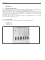
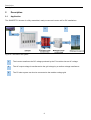
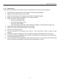
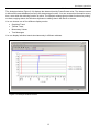
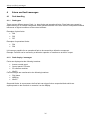
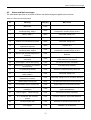
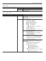
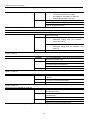
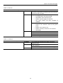
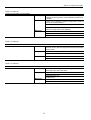
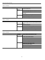
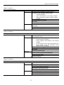
SINVERT 350, SINVERT 420 and SINVERT 500 TL
Operating Manual – 11/2009
SINVERT
Answers for environment.
1
Photovoltaic
SINVERT
Introduction
1
Description
2
Hardware operation
3
Alarm and fault messages
4
Support
5
SINVERT 350, SINVERT 420 and
SINVERT 500 TL
Safety instructions
These Operating Instructions contain information which you should observe to ensure your own personal safety
as well as to protect the product and connected equipment. The notices referring to your personal safety are
highlighted in the manual by a safety alert symbol. Notices referring only to equipment damage have no safety
alert symbol. Warnings are shown in descending order according to the degree of danger as follows.
DANGER
indicates that death or serious injury will result if proper precautions are not taken.
WARNING
indicates that death or serious physical injury may result if proper precautions are not taken.
CAUTION
with a safety alert symbol indicates that minor personal injury can result if proper precautions are not taken.
CAUTION
without a safety alert symbol indicates that damage to property may result if proper precautions are not taken.
CAUTION
indicates that an unwanted result or state may occur if the relevant instruction is not observed.
In the event of a number of levels of danger prevailing simultaneously, the warning corresponding to the highest
level of danger is always used. A warning that uses a safety alert symbol indicating possible personal injury may
also include a warning relating to material damage.
Qualified personnel
The associated equipment / system may only be set up and operated in conjunction with this documentation. The
equipment / system may only be commissioned and operated by qualified personnel. For the purpose of the
safety information in these Operating Instructions, a "qualified person" is someone who is authorized to energize,
ground, and tag equipment, systems, and circuits in accordance with established safety procedures.
Proper handling
Note the following:
WARNING
The equipment may only be used for single-purpose applications explicitly described in the catalog and in the
technical description, and only in conjunction with third-party devices and components approved by Siemens.
This product can only function correctly and safely if it is transported, stored, set up, and installed correctly, and
operated and maintained as recommended.
Trademarks
All names shown with the trademark symbol ® are registered trademarks of Siemens AG. Third parties using for
their own purposes any other names in this document which refer to trademarks might infringe upon the rights of
the trademark owners.
Disclaimer of liability
We have checked that the contents of this document correspond to the hardware and software described.
However, since deviations cannot be precluded entirely, we cannot guarantee full consistency. The information
given in this publication is reviewed at regular intervals and any corrections that might be necessary are made in
the subsequent editions.
Siemens AG
A5E
Ⓟ 12/2009
Copyright © Siemens AG 2009
Subject to change
Contents
1
2
3
4
5
Introduction ................................................................................................................... 6
1.1
About this documentation........................................................................................ 6
1.1.1
Scope of validity .............................................................................................. 6
1.1.2
Target group.................................................................................................... 7
1.1.3
Document structure ......................................................................................... 7
1.1.4
History ............................................................................................................. 7
Description .................................................................................................................... 8
2.1
Application............................................................................................................... 8
Hardware operation ...................................................................................................... 9
3.1
Commissioning the inverter..................................................................................... 9
3.1.1
Instructions and safety information.................................................................. 9
3.1.2
Switching off and disconnecting the power supply........................................ 10
3.1.3
Switching on .................................................................................................. 11
3.2
Operating the inverter ........................................................................................... 12
3.2.1
Operator panel .............................................................................................. 12
3.2.2
Operating mode............................................................................................. 14
3.2.3
Switching the inverter on and off ................................................................... 14
3.2.4
Local/Remote selector switch........................................................................ 14
3.2.5
Fault reset ..................................................................................................... 15
3.2.6
Displaying currently active alarms and faults ................................................ 15
3.2.7
Adjusting the voltage ..................................................................................... 15
3.2.8
Grid LED indicator bar................................................................................... 15
3.2.9
Status display ................................................................................................ 15
3.2.10
Fault display .................................................................................................. 16
3.2.11
Numerical display .......................................................................................... 16
3.3
Communication with the inverter........................................................................... 17
3.3.1
WEB’log......................................................................................................... 17
3.3.2
WinCC ........................................................................................................... 17
3.3.3
PPsolar.......................................................................................................... 17
Alarm and fault messages ......................................................................................... 26
4.1
Fault handling........................................................................................................ 26
4.1.1
Fault types..................................................................................................... 26
4.1.2
Fault display / messages............................................................................... 26
5.2..................................................................................................................................... 26
4.2
Alarm and fault messages..................................................................................... 27
5.2.3.............................................................................................................................. 28
4.2.1
Faults – Causes/diagnostics/remedial measures.......................................... 29
Support ........................................................................................................................ 41
5.1
Contact addresses ................................................................................................ 41
Tables
Table 3-1 Pin assignment X5 (SUB-D 9-pin/ RS422 for PPsolar) ........................................... 13
Table 4-1 Alarm and fault messages................................................................................. 27
Table 4-2 ISO fault .......................................................................................................... 30
Table 4-3 Fault 0 ............................................................................................................. 31
Table 4-4 Faults 1 and 33 ................................................................................................ 31
Table 4-5 Faults 4 and 47 ................................................................................................ 32
Table 4-6 Fault 6 ............................................................................................................. 32
Table 4-7 Fault 12 ........................................................................................................... 32
Table 4-8 Fault 14 ........................................................................................................... 32
Table 4-9 Fault 36 ........................................................................................................... 33
Table 4-10 Fault 37 ......................................................................................................... 33
Table 4-11 Fault 39 ......................................................................................................... 34
Table 4-12 Fault 40 ......................................................................................................... 34
Table 4-13 Fault 43 ......................................................................................................... 35
Table 4-14 Fault 48 ......................................................................................................... 35
Table 4-15 Fault 62 ......................................................................................................... 35
Table 4-16 Fault 63 ......................................................................................................... 36
Table 4-17 Fault 64 ......................................................................................................... 36
Table 4-18 Fault 65 ......................................................................................................... 36
Table 4-19 Fault 91 ......................................................................................................... 37
Table 4-20 Fault 92 ......................................................................................................... 37
Table 4-21 Fault 93 ......................................................................................................... 37
Table 4-22 Fault 94 ......................................................................................................... 38
Table 4-23 Fault 95 ......................................................................................................... 38
Table 4-24 Fault 96 ......................................................................................................... 39
Table 4-25 Fault 97 ......................................................................................................... 39
Table 4-26 Fault 98 ......................................................................................................... 39
Figures
Figure 1-1 SINVERT 350/420/500 TL ................................................................................... 6
Figure 2-1 Overview of PV system ...................................................................................... 8
Figure 3-1 Front view of control panel ............................................................................. 12
Figure 3-2 Front view of control panel ............................................................................. 13
Figure 3-3 Fast ON button and local/remote selector switch .............................................. 14
Figure 3-4 Main menu PPsolar ......................................................................................... 17
Figure 3-5 System Diagram PPsolar .................................................................................. 18
Figure 3-6 Control Panel PPsolar ...................................................................................... 19
Figure 3-7 Oscilloscope function PPsolar .......................................................................... 20
Figure 3-8 Process Data window PPsolar........................................................................... 21
Figure 3-9 Data Storage PPsolar ....................................................................................... 24
Figure 3-10 Analysis window PPsolar ............................................................................... 25
Introduction
1.1 About this documentation
1
Introduction
1.1
About this documentation
This manual will provide you with guidance in the use of SINVERT PV inverters. It provides you with a
detailed overview of all the information you need to know about SINVERT PV inverters.
We have checked that the contents of this document correspond to the hardware and software described.
However, since deviations cannot be precluded entirely, we cannot guarantee full consistency. The
information given in this publication is reviewed at regular intervals and any corrections that might be
necessary are made in subsequent editions.
We would be pleased to receive any feedback or suggestions for improvements from you. You will find
our contact details in Chapter 5, "Support".
1.1.1 Scope of validity
This system manual is valid for the following basic models of the SINVERT PV inverter:
•
SINVERT 350 M
•
SINVERT 420 M
•
SINVERT 500 M TL
Figure 1-1 SINVERT 350/420/500 TL
6
Introduction
1.1 About this documentation
and their master-slave variants:
•
•
•
SINVERT 700 MS (two SINVERT 350 inverters in parallel)
SINVERT 1000 MS (three SINVERT 350 inverters in parallel)
SINVERT 1400 MS (four SINVERT 350 inverters in parallel)
•
•
•
SINVERT 850 MS (two SINVERT 420 inverters in parallel)
SINVERT 1300 MS (three SINVERT 420 inverters in parallel)
SINVERT 1700 MS (four SINVERT 420 inverters in parallel)
•
•
•
SINVERT 1000 MS TL (two SINVERT 500 TL inverters in parallel)
SINVERT 1500 MS TL (three SINVERT 500 TL inverters in parallel)
SINVERT 2000 MS TL (four SINVERT 500 TL inverters in parallel)
1.1.2 Target group
This documentation contains information of interest to the following target groups:
•
•
Operators
Service personnel
1.1.3 Document structure
These installation and operating instructions are divided into five chapters:
Chapter
Contents
Introduction
Description
Information about the operating manual, overview of inverter types,
target group
Applications of SINVERT PV inverters
Hardware operation
Inverter operating guide
Alarm and fault messages
List of alarm and fault messages, causes and measures
Contact details and information about support for SINVERT inverters
and products by Siemens I IA S PV
Support
1.1.4 History
Currently released editions of this manual:
Edition
Remark
11/2009
First edition
7
Description
2.1 Application
2
Description
2.1
Application
The SINVERT PV inverter is a fully assembled, ready-to-connect inverter unit for PV installations.
1
2
3
Figure 2-1 Overview of PV system
1
The inverter transforms the DC voltage produced by the PV modules into an AC voltage.
2
The AC output voltage is transformed to the grid voltage by a medium-voltage transformer.
3
The PV solar system can thus be connected to the medium-voltage grid.
8
Hardware operation
3.1 Commissioning the inverter
3
Hardware operation
3.1
Commissioning the inverter
Commissioning an installation requires certain switching operations to be performed. This type of work
must always be undertaken by qualified, properly trained personnel. Failure to perform switching
operations correctly can result in significant property damage and serious physical injury. The
components described in this manual operate at hazardous voltages and currents. Proper precautions
must be taken during the commissioning process. This manual describes only the manual process of
switching the PV system on and off.
The system must be switched on and off manually in order to carry out performance tests and
maintenance procedures.
CAUTION
The instructions and guidelines relating to operation and control of the installation contained in the operating
manuals for the switching equipment and other devices described here must be adhered to.
3.1.1 Instructions and safety information
In accordance with the relevant standards and legislation (e.g. DIN VDE 0105), properly trained
specialists must always be employed to operate and control electrical equipment.
All employees authorized to undertake switching tasks must receive instruction in accordance with the
relevant standards and legislation (in Germany, at least once annually in accordance with BGV A1 §4
(Institute for Statutory Accident Insurance and Prevention/Instruction of Insured Persons)).
Follow all safety guidelines and work instructions stipulated by the relevant legislation and standards.
Never take any action which would endanger either yourself or others.
The five safety rules in Germany:
1. Isolate from power supply
2. Provide a safeguard to prevent unintentional reclosing
3. Make sure that the equipment is de-energized
4. Ground and short
5. Cover or place guards around adjacent live parts
CAUTION
The safety rules (for example, DIN VDE 0105 – 100 § 6.2 in Germany) are especially applicable to switching or
voltage disconnection operations.
If you are working abroad, you must adhere to the relevant local safety rules. Always pay particular care and
attention when working on or around electrical equipment.
9
Hardware operation
3.1 Commissioning the inverter
3.1.2 Switching off and disconnecting the power supply
The entire system must be disconnected from the power supply before test and maintenance work can
be carried out in the containers. Carry out these tasks in the sequence given below:
1.
2.
3.
4.
Press the OFF key briefly on the control panel of every inverter.
For reasons of safety, also press the Fast Stop button (if one is installed) in the inverter room.
Disconnect the external power supply (most commonly in the AC distribution cabinet) by opening
the fuse switch disconnector or by switching off the miniature circuit breaker.
Open the AC-side and DC-side fuse switch disconnectors in all inverters and remove the fuses,
including the fuse holder, or remove the fuse cartridge with a fuse tong. This means that the
inverter cannot be switched on again (remember the five safety rules).
DANGER
The AC and DC connections are still live externally!
5.
6.
In order to disconnect the AC end completely from the power supply, the relevant medium-voltage
transformer must be switched off at the medium-voltage switchgear. After switching off, open the
medium-voltage isolator and close the medium-voltage grounding switch. The machine switching
operations on the medium-voltage components must be performed via the power supply company
or an authorized person.
In order to disconnect the DC end completely from the power supply, all relevant junction boxes of
the generator and coupling boxes (if installed) must be disconnected. The disconnectors in the
generator junction boxes and/or coupling boxes (if installed) can be switched under load. In
contrast, fuse switch disconnectors must not be switched under load. Likewise, fuse cartridges in
fuse holders must not be removed under load.
DANGER
Fuse switch disconnectors in the inverters and junction boxes must not be switched under load! Do not remove
fuse cartridges when they are under load!
10
Hardware operation
3.1 Commissioning the inverter
3.1.3 Switching on
The inverter is switched on in the same way as it is switched off, but in the reverse sequence.
1.
2.
3.
4.
5.
6.
7.
8.
9.
10.
11.
12.
Check that all connections have been made correctly (including polarity).
Switch on the junction boxes in the PV field.
Switch on the external power supply for the medium-voltage switchgear.
Switch on the external power supply for the inverter container.
Close the medium-voltage breaker.
o Open the grounding switch.
o Close the switch disconnector.
o Close the circuit breaker.
o Note: Depending on the type of MV switchgear installed, the step sequence might vary.
Close the DC fuse switch disconnectors in all inverters.
Close the AC fuse switch disconnectors in all inverters.
Unlock the "Fast Stop" button.
Turn the keyswitch on all inverters from "Auto" to "Test" and back to "Auto" in order to reset
settings.
If insolation levels are sufficiently high, the system will restart automatically after 30 minutes.
To start the system immediately, you must turn the keyswitch on the master to the test position.
Then press the internal key "S111".
The DC contactors are automatically closed one after the other. The inverter is then started and
the AC contactor is immediately closed. Now turn the keyswitch to "Auto".
11
Hardware operation
3.2 Operating the inverter
3.2
Operating the inverter
3.2.1
Operator panel
Figure 3-1 Front view of control panel
1
Grid LED indicator bar
2
Status display
3
Fault display
4
Display
5
Service interface (RS 232)
6
Keyswitch (operating mode)
7
OFF key
12
Hardware operation
3.2 Operating the inverter
Figure 3-2 Front view of control panel
Table 3-1 Pin assignment X5 (SUB-D 9-pin/ RS422 for PPsolar)
Pin
1
5
6
9
Signal
RRS485P
TRS485N
TRS485P
RRS485N
13
Hardware operation
3.2 Operating the inverter
3.2.2 Operating mode
You can choose between modes "Automatic" and "Test".
In Test mode, you can adjust the DC voltage manually. In Automatic mode, the inverter determines the
Maximum Power Point (MPP) automatically. It also displays currently active fault messages.
To select Test mode, turn the keyswitch to the "TEST" position. To select Automatic mode, turn the
keyswitch to the "AUTO" position.
3.2.3 Switching the inverter on and off
The inverter switches on and off automatically in AUTO mode. Manual switching on and off is possible in
both TEST mode and AUTO mode.
The control electronics and control panel of the inverter are switched off temporarily in order to save
energy. When the inverter is in this state, it cannot be operated via the panel. However, you can switch
on the control electronics and control panel for maintenance and commissioning purposes. To do so,
open the cabinet door and press the Fast ON button inside the inverter. Once you have switched on the
panel, you can switch the inverter on and off as described below.
To switch off the inverter during operation, briefly press the OFF button on the operator panel (less than 3
seconds).
To switch on the inverter, briefly press the OFF button on the operator panel (less than 3 seconds) in
TEST mode.
3.2.4 Local/Remote selector switch
If the selector switch is set to Local, errors can only be acknowledged locally and the inverter can be
started manually. Remote access is blocked in this switch position.
In the Remote position, errors can also be acknowledged and the inverter started by a plant monitoring
system (such as WinCC). In this position, the inverter can also be operated locally and started manually.
Figure 3-3 Fast ON button and local/remote selector switch
14
Hardware operation
3.2 Operating the inverter
3.2.5 Fault reset
You can reset a fault by turning the keyswitch from "AUTO" to "TEST" and back to "AUTO" or vice versa.
If the inverter has been disabled due to a fault, it can now be activated again.
3.2.6 Displaying currently active alarms and faults
In Automatic mode, you can display the last ten alarm and fault codes. To do this, press the OFF key in
Automatic mode for more than 3 seconds. The alarm and fault codes will then appear in sequence on the
two-digit display.
3.2.7 Adjusting the voltage
In Test mode, you can adjust the voltage at the DC connections for test and commissioning purposes. To
do this, press the OFF key in Test mode for more than 3 seconds. The voltage is then adjusted in
increments of 10°V across the entire voltage window. The two-digit display shows the first two digits of
the DC voltage value (for example, 55 represents a voltage of 550 V DC).
3.2.8 Grid LED indicator bar
The grid LED indicator bar shows the power output of the inverter system in increments of 25%. The
display refers to the output of the relevant individual inverter. In Automatic mode, the total system output
of the master/slave unit is shown on the two-digit display.
3.2.9 Status display
The status display indicates the status of the whole system.
Insulation fault/alarm (LED "ISO FAULT")
If the insulation resistance between the PV field and ground is too low, there is a risk of electric shock if
you touch the PV modules. The inverter is equipped with an insulation monitoring device which detects
this hazard and outputs an alarm.
If the insulation resistance is in the range that is dangerous for people, an insulation warning is triggered
and the "ISO FAULT" LED flashes.
If the insulation value is in the range that is dangerous for the system, the "ISO FAULT" LED lights
continuously and the inverter releases the relevant inputs. Even when switched off, a system with an
insufficient insulation value represents a danger.
The cause of the low insulation value must be immediately rectified.
DANGER
The cause of the low insulation value must be immediately rectified.
Even when switched off, a system with an insufficient insulation value represents a danger.
CAUTION
Insulation faults reduce system yield!
The cause of the low insulation value must be immediately rectified.
Ready to run (LED "ONLINE")
The "ONLINE" LED lights up steadily while the inverter is in operation. The DC contactors and the main
AC contactor are closed and the power unit is generating voltage.
15
Hardware operation
3.2 Operating the inverter
Maximum Power Point (LED "MPP")
The power which can be generated by a PV system depends on the level of insolation and the
temperature of the PV modules. The inverter control unit is equipped with a "Tracker" which automatically
tracks the MPP (Maximum Power Point) of the PV field in Automatic mode. As soon as the inverter
tracker has found the MPP, the LED "MPP" lights up.
A flashing "MPP" LED indicates throttling of the inverter due to overtemperature of the cooling element.
Standby operation (LED "STANDBY")
The LED "STANDBY" lights up if the power unit of the inverter is switched off, but the control electronics
and control panel are switched on (for example, if the PV field output is not sufficient to compensate for
the losses, or if the inverter has been switched off manually). The AC contactor is open, and the DC
contactors are open, closed or switching between these two states (in order to check whether sufficient
voltage/output is available to start operation).
Automatic mode / Test mode
The LEDs "AUTO" and "TEST" indicate the current operating mode of the inverter.
Line (grid) status (LED "LINE OK")
The inverter is equipped with a monitoring unit for the three-phase AC grid. This can detect grid faults or
failures. If a fault is detected, the inverter shuts the system down to prevent the regeneration of
hazardous voltages to the grid. The LED "LINE OK" indicates that the grid voltage and frequency are
within the programmed limit values.
3.2.10 Fault display
If malfunctions in the PV installation develop which affect only certain parts of the system and do not
prevent it from regenerating energy to the grid, operation continues and the inverter triggers an alarm. If a
malfunction develops which affects the entire system, the inverter is switched off with a fault message.
The LED "ALARM" flashes to indicate an alarm.
The LED "FAULT" lights up steadily to indicate a fault.
3.2.11 Numerical display
In Automatic mode, the output of the whole PV system as a percentage of rated output is shown on the
two-digit display. If the output is more than 99%, a value of "00" is displayed. At the same time, the LED
">100%" lights up in the grid indicator bar.
In Test mode, the two-digit display shows the first two digits of the set DC voltage value (for example, 55
represents a voltage of 550 V DC).
Codes for malfunctions
In the event of a fault or alarm (in Test or Automatic mode), a corresponding code appears on the
display. The meaning of these codes can be found in table 4-1. The code will remain displayed until the
operator resets the alarm or fault by means of the keyswitch.
16
Hardware operation
3.3 Communication with the inverter
3.3
Communication with the inverter
Various possible methods of communicating with the inverter are presented below.
3.3.1 WEB’log
WEB’log is generally used to log inverter data, i’checker data and meteorological data which has been
recorded while the inverter is in operation. This data can be represented graphically in an Internet portal.
In systems with WinCC, WEB’log serves as an interface for the i'checker sensors.
3.3.2 WinCC
The description of functions and directions for use of WinCC can be found in a separate document.
3.3.3 PPsolar
By selecting button "New" in the main menu, you can access the screen for entering the names of the
connected SINVERT units. You must enter the relevant names (up to maximum 40 characters in length)
in the box "SINVERT name". The slave addresses are automatically incremented from 0 to 31, which
means that you can register up to 32 SINVERT inverters in this program. The maximum permissible
length of data cable to the local PC is 100 m. Up to four SINVERT units can be displayed at one time. If
more than four are displayed, the transmission rate decreases significantly.
Figure 3-4 Main menu PPsolar
By double clicking on the name of an inverter, you will branch to submenus System Diagram, Control
Panel, Oscilloscope, Process Data, Data Storage, etc. Double click on one of these to open the relevant
window.
The System Diagram (Figure 3-5) shows the entire PV plant, including the PV generator, DC contactor,
inverter, AC contactor and grid interface. The status of the system components and the energy flow
within the system are represented by different colors in the diagram.
17
Hardware operation
3.3 Communication with the inverter
Gray:
Blue:
Green:
Red:
No information available about the system components
System components are ready; no energy flowing
System components are running; energy is flowing
System components are malfunctioning
Figure 3-5 System Diagram PPsolar
The System Diagram contains the electrical data of the entire PV installation plus all important
information about the operating status of the system (voltage, current, output, frequency). Additional
meteorological measured data, such as insolation, temperature and wind speed, can also be displayed (if
the corresponding sensors are installed). The windows for faults and alarms contain a list in plain text of
all malfunctions and alarms.
18
Hardware operation
3.3 Communication with the inverter
The Control Panel (Figure 3-6) contains the same display and control elements as the control panel of
the SINVERT PV inverter.
Figure 3-6 Control Panel PPsolar
19
Hardware operation
3.3 Communication with the inverter
The Oscilloscope function (Figure 3-7) enables you to record data in two channels and to print output
voltages, output currents, inverter currents and the PV generator voltage. The right to use this special
function is reserved for Siemens customer service personnel.
The trigger control function enables you to choose the events which will trigger measured data
recordings. A measurement can be triggered by a malfunction, a grid (mains) failure or when the inverter
is switched on or off. You can also manually trigger a recording.
You can set the X axis scaling to one of three values:
Fine:
Medium:
Coarse:
approx. 2 ms per division
(scan rate 12 kHz with 255 pixels = 21.25 ms)
approx. 25 ms per division
(scan rate 1 kHz with 255 pixels = 255 ms)
approx. 100 ms per division
(scan rate 250 Hz with 255 pixels = 1020 ms)
Figure 3-7 Oscilloscope function PPsolar
20
Hardware operation
3.3 Communication with the inverter
The Process Data window (Figure 3-8) displays information about the inverter. For the sake of better
clarity, the window is divided into a number of panes. You can specify the number of panes and their
content in a configuration file. In the default configuration, the content of the individual panes is as
follows:
Device Information
The device information box displays the software version of the CU4 control unit. The date of software
creation (day, month and year) is specified. In addition, the box also shows the performance class,
MLFB, operating hours and status of the inverter (sequence control status).
Figure 3-8 Process Data window PPsolar
SINVERT-Settings
You can adjust the inverter settings in this screen, e.g. normal operation, standard and expert mode
(depending on access authorization).
The setting Normal Operation permits access only to monitoring functions, but inhibits changes to
parameter values.
The setting Standard permits parameter values to be changed.
The setting Experts permits special, extensive changes to parameter values.
Various functions can be selected for the settings. When you select the Return function, values cannot
be changed. This means that a pure monitoring function is assigned to the setting. The function Initial
Program Loading essentially initializes the inverter and is generally only used to restore the Siemens
factory settings. The function Commissioning permits parameters to be changed during the
commissioning process.
21
Hardware operation
3.3 Communication with the inverter
Actual Value Summary
The window with the overview of actual values displays a summary of key data of the PV system.
You can alter data (e.g. reactive power transfer from SINVERT to the three-phase AC grid) in this window
when it is active.
Actual values
The Actual Values window displays all electrical data of the PV system, as well as information about
weather and insolation.
You can alter data (e.g. reactive power transfer from SINVERT to the three-phase AC grid) in this window
when it is active.
22
Hardware operation
3.3 Communication with the inverter
The Data Storage window (Figure 3-9) is used to start, stop and configure the data archiving function of
the PowerProtect solar system. The data to be archived, the scan rate, the data length and archiving path
are specified in this window.
The scan rate (tscan > xxs) and the data length, i.e. the period for which the data will remain stored in the
archive file, can be freely selected (tfile > 1 day). Furthermore, you can define the number of panes and
their content to suit your own needs by means of parameters in a configuration file. In the default
configuration, the following panes are available:
• Weather conditions
• PV generator
• Mains interface
• Energy
The archiving function in PowerProtect solar is purely a data archiving function, but does not allow
visualization or analysis of data.
Weather conditions
All weather data available for the PV system are displayed in the Weather Conditions window. Check the
boxes for the values that you want PowerProtect solar to store. You can select the following data (*
provided the relevant sensors are installed in the PV system):
• Temperature *
• Wind velocity *
• Global insolation *
PV Generator
The PV Generator window displays all available information about the PV generator. Check the boxes for
the values that you want PowerProtect solar to archive. You can select the following data (* provided the
relevant sensors are installed in the PV system):
• Module temperature *
• Module irradiation *
• Voltage (V) PV Generator
• Current (I) PV Generator
• Power (P) PV Generator
Mains Interface
The Mains (Grid) Interface window displays all the available data about the grid connection. Check the
boxes for the values that you want PowerProtect solar to archive. You can choose from the following
values:
• Phase voltage
• Phase current
• Phase reactive current
• Phase apparent power
• Total active power
• Total reactive power
• Total apparent power
23
Hardware operation
3.3 Communication with the inverter
Energy
The Energy window displays all the available energy data of the PV system. Check the boxes for the
values that you want PowerProtect solar to archive. You can select the following data (* provided the
relevant sensors are installed in the PV system):
• Energy - day
• Energy - month
• Energy - year
• Energy - total
Figure 3-9 Data Storage PPsolar
24
Hardware operation
3.3 Communication with the inverter
The Analysis window (Figure 3-10) displays the data archived by PowerProtect solar. The data are saved
in Microsoft Access database format by the data storage function. You can access this information at any
time, even while the archiving function is active. The Analysis window also provides functions for printing
out data, copying data to the Windows clipboard or editing data in MS Excel or Access.
You can choose one of four different display modes:
• Graphical Trend
• Tabular Trend
• Momentary Values
• Text Messages
You can display individual trends simultaneously in different windows.
Figure 3-10 Analysis window PPsolar
25
Alarm and fault messages
4.1 Fault handling
4
Alarm and fault messages
4.1
Fault handling
4.1.1
Fault types
There are two different types of fault, i.e. plant faults and operational faults. Plant faults are caused by
malfunctioning of an inverter component, while operational faults occur as a result of unexpected external
influences or logical conditions of the control software.
Examples of plant faults:
• F48
• F65
• F97
Examples of operational faults:
• F94
• F96
It is however possible for an operational fault to be caused by a defective component.
Example: Fault 96 can be caused by a defective capacitor or transformer at the AC output.
4.1.2
Fault display / messages
Faults are displayed at the following locations:
• Inverter control panel
• Control panel in PPsolar
• S7 software modules
• WinCC
Fault messages are transferred to the following locations:
• FAX Alarm
• WEB’log
• WinCC
Sequential faults: In some cases, the first fault can trigger further sequential faults which are
superimposed on the first fault or overwrite it on the display.
26
Alarm and fault messages
4.2 Alarm and fault messages
4.2
Alarm and fault messages
The table below provides an overview of alarm and fault messages supplied on the inverter.
Table 4-1 Alarm and fault messages
No.
Meaning
Category
0
Manual Off
Fault
1
Inverter power unit is signaling
overtemperature, stage 1
Alarm
Ambient temperature too high, fan defect,
interruption in auxiliary supply to fans
4
Inverter overload; i2-t protection
(alarm), stage 1
Alarm
Parameter setting error
6
Overload
Alarm
Parameter setting error
12
Inverter is in commissioning mode
Alarm
Parameter setting error
14
Fans have exceeded useful life,
replacement required
Alarm
Replace fans
Fault
Ambient temperature too high, fan defect,
interruption in auxiliary supply to fans
Fault
Fast Stop button pressed or AC contactor
defective
Fault
DC link voltage too low, current too high, inverter
in test mode, no Vdc setpoint
33
36
37
Inverter power unit is signaling
overtemperature, stage 2
Fast Stop (1) activated, AC contactor
defective (no checkback signal from
contactor)
Several start attempts in quick
succession
Main cause
39
Overvoltage in the DC link (VDCgg)
Fault
PV field is incorrectly connected
40
Fast Stop (2), Fast Stop via customer
terminal block
Fault
Fast Stop button pressed
43
VCE protection activated
Fault
Defective component in the power unit
47
Inverter overload; i2-t protection
(fault), stage 2
Fault
Parameter setting error
48
Regeneration to the DC link or
defective AC contactor
Fault
Parameter setting error, AC contactor defective
49
Undervoltage in the DC link
Alarm
PV field is disconnected from the inverter
62
No checkback signal "Inverter ON"
Fault
Signal cable is not connected correctly
63
Direct current too high or signal cable
is defective
Fault
Parameter setting error, fault at S7 analog input,
signal cable defective
Fault
PV field is incorrectly connected
64
Vdc too high or
Vdc/dt too high
65
No checkback "AC contactor closed"
or no checkback "DC contactor
closed"
Fault
Contactor defective, signal cable defective
66
General inverter fault
Fault
Defective component in the power unit
91
Fuse tripped
Fault
Overvoltage or short circuit has occurred,
hardware may be defective
27
Alarm and fault messages
4.2 Alarm and fault messagesAlarm and fault messagesAlarm and fault messages
92
93
DC overvoltage protection has
responded (or fuse (if installed) has
tripped)
Fast Stop activated or overvoltage on
medium-voltage transformer
Fault
Overvoltage (lightning strike) has occurred
Fault
Fast Stop button pressed, fault in cooling system
of medium-voltage transformer
94
Profibus error
Fault
95
Grid frequency outside tolerance
Fault
96
Grid voltage outside tolerance
Fault
97
No checkback from DC link contactor
or failure of cooling fan in the
container
Fault
DC link contactor defective, signal cable
defective, container fan defective
98
Symmetry fault in the PV field
Fault
Fault in at least one PV field string
100
Image in the display (WinCC)
No fault
(generated by the control unit)
Insulation fault in the PV field (alarm)
Alarm
Cable damaged, module damaged, rain
Insulation fault in the PV field (fault)
Fault
Cable damaged, module damaged, rain
LED
"ISO"
flashing
LED
"ISO" lit
steadily
28
Phase sequence is anti-clockwise, grid failure,
parameter setting error
Grid voltage outside tolerance (possibly grid
failure as well), voltage measurement error,
parameter setting error
Alarm and fault messages
4.2 Alarm and fault messages
4.2.1 Faults – Causes/diagnostics/remedial measures
First acknowledge the fault with the keyswitch on the control panel.
Check the following if the inverter has not been in operation:
•
•
•
•
Polarity of the PV field input
Polarity of the DC link connection
AC phase sequence
AC voltage (phase-phase, phase-N)
Check the following if the inverter has been in operation:
•
•
•
•
•
Is the Fast Stop button in the locked position?
Is the external power supply available?
Is the control voltage (24 V DC) present at the relevant terminals?
Is the grid voltage within tolerance?
Have fuses blown or have automatic fuses tripped? If yes, find the cause of the problem.
If none of the reasons above is the source of the fault, it may have been caused by a problem on the
control unit.
If a CU printed circuit board is defective, it must be replaced with a new one. Never install a CU in a
different device to check whether it is defective or not.
This could cause very serious damage to the other device.
(Read out and check all CU parameters.)
(Read out and check the S7 HW Config.)
Differences in potential in the PV field
If a PV system is not yielding the required output, the problem could indicate a difference in potential.
This means that there is a difference in voltage between the field segments. Because the field segments
are connected in parallel, an average voltage value is supplied under these conditions and this means in
turn that the field segments are not operating at the MPP.
To identify this type of fault, measure the no-load voltage and the MPP voltage at the inverter inputs and
compare the measured values. A deviation of more than 10 V is an effective difference in potential which
will cause a reduction in output.
29
Alarm and fault messages
4.2 Alarm and fault messages
Table 4-2 ISO fault
ISO fault
Causes
Diagnostics
Measures
30
Damaged, worn-through cables (loose, buffeted by
wind)
Cables damaged by animals
Water in junction box
Damaged insulation and ingress of water to cable
duct
Defective power unit
Bending device defective
Defect in PV module (damaged)
High air humidity (causes high leakage currents)
Check the sensitivity (limit values) of the insulation
monitor using a decade resistor
Repair the cabling
Empty and dry out the junction boxes and / or cable
ducts
Repair / replace the drive
Alarm and fault messages
4.2 Alarm and fault messages
Table 4-3 Fault 0
(Alarm) General fault on transformer
The hardware contact in the power unit has tripped.
There is a defect in the inverter.
Replace the affected components.
Replace the drive.
Condition
Causes
Measures
Table 4-4 Faults 1 and 33
Message 1 (alarm): Inverter is signaling overtemperature, stage 1
Fault 33 (alarm): Inverter is signaling overtemperature, stage 2
An excessive heatsink temperature in the inverter has
Condition
been detected.
The thermoclick circuit for the reactors and transformers
has been interrupted.
Causes
Cooling system is not working properly
o
Drive fan is not running
⇒ Fan motor is defective
⇒ Start capacitor is defective
⇒ No power supply to fan
⇒
o
o
USI is defective
⇒
Infeed transformer is defective
Heatsink is blocked
Drive fan speed is too low
⇒ Infeed transformer is connected to tap
460 V instead of 400 V
Heat generation is exceeding tolerance
o
Current is too high
⇒ Parameter setting error (CU software –
current limit value)
o
IGBT module defective
Fault in measured-value sensing
o
Temperature sensor in heatsink is defective
o
Temperature sensor connection is defective
o
CU data input is defective
Reactor or transformer is overheating (fault 33 only,
without preceding warning level 1 in the PPsolar
event memory)
o
Cooling system is not working properly
⇒ Housing fans are not running
⇒ Fans are defective
⇒ Thermostat is defective
⇒ Thermostat is incorrectly set
⇒ Air intake is restricted
⇒ Air inlet grille on housing is clogged
up
⇒ Air outlet is restricted
31
Alarm and fault messages
4.2 Alarm and fault messages
Causes
Inlet air temperature too high
o
Air inlet to switchroom is blocked
o
Air outlet from switchroom is restricted
o
Ambient temperature is too high
Replace the defective components
Measures
Check the parameter settings
Clean or enlarge the air inlet
Table 4-5 Faults 4 and 47
Fault 4 (alarm): Inverter overload, I²t monitoring, stage 1
Fault 33 (alarm): Inverter is signaling overtemperature, stage 2
The CU has detected a current which is higher than the
Condition
permissible l²t limit.
Causes
Excessive current
o
Parameter setting error (CU software –
current limit value)
Fault in measured-value sensing
o
Parameter setting error (CU software - limit
value I2t)
Measures
Adjust the parameter settings
Condition
The CU has detected a current which is higher than the
selected permissible value.
USI is defective
Table 4-6 Fault 6
(Alarm) overload
Causes
AC current transformer defective
Parameter setting error
Measures
Adjust the parameter settings
Condition
The CU has detected that commissioning mode is
selected
Causes
The CU is in commissioning mode
Measures
Set the CU operating mode to "Reversion"
Condition
The hours counter in the CU has reached "0" (hours are
counted backwards)
Causes
The fan has operated for 35,000 hours since initial
commissioning
The value set initially for the hours counter was too low
Replace the fan.
Set the hours counter to 35,000 hours.
Table 4-7 Fault 12
(Alarm) System is in commissioning mode
Table 4-8 Fault 14
(Alarm) Fan has exceeded its useful life
Measures
The fans do not necessarily develop defects after working for this number of hours.
32
Alarm and fault messages
4.2 Alarm and fault messages
Table 4-9 Fault 36
(Alarm) AC contactor defective (no checkback), or Fast Stop button pressed
There is no signal at input 11/12 of the CU (green
Condition
connector); transferred via Profibus to the S7; drive has
received an ON command.
Causes
No power supply for Fast OFF
Fast Stop button has been pressed
Wire break in the Fast OFF circuit
Defect in power supply for Fast OFF
Fire alarm system has been activated (if
installed)
No checkback signal from the AC contactor
o Defect in AC contactor control circuit (power
pack)
o Defect in AC contactor coil
o Defect in auxiliary contacts of AC contactor
o Wire break
Unlock the Fast Stop button.
Replace the AC contactor
Unlatch the contacts of the AC contactor
Repair the cabling
o
o
o
o
Measures
Table 4-10 Fault 37
(Alarm) Several restart attempts in succession
Condition
The S7 has tried several times without success to
restart the drive
Causes
Fault in the drive
Operational fault (might be rectified automatically)
Repair the drive
Measures
33
Alarm and fault messages
4.2 Alarm and fault messages
Table 4-11 Fault 39
(Alarm) DC link overvoltage
Condition
The CU has detected a DC voltage in excess of the
permissible value
Causes
The measured DC voltage is too high
o The available DC voltage is too high
o
⇒ The PV field has been connected
incorrectly (the voltage rises too sharply at
high temperatures, mostly under no load)
DC voltage measurement error
⇒ Parameter setting error (CU software)
⇒ Power pack defective (measured-value
sensing)
Measures
Adjust the parameter settings
Replace the power pack
Change the connection and/or the cabling of the PV field
Connect a braking resistor
Table 4-12 Fault 40
(Alarm) Fast Stop 2; Fast Stop via customer terminal block
There is no signal at input 11/12 of the CU (green
Condition
connector); transferred via Profibus to the S7; drive has
not received an ON command.
Causes
No line voltage for Fast OFF
o
o
o
o
o
Measures
Fast Stop button has been pressed
Wire break in the Fast OFF circuit
No power supply for Fast OFF
Fire alarm system has been activated (if
installed)
No jumper on terminal strip X50 (if no Fast
Stop button is connected)
Unlock the Fast Stop button.
Repair the cabling
34
Alarm and fault messages
4.2 Alarm and fault messages
Table 4-13 Fault 43
(Alarm) Vce monitor has responded
The CU has detected an inadmissible circuit voltage
(voltage on semiconductor module between emitter and
collector).
Power unit is defective (various components could be
the source of the problem)
Condition
Causes
Transformer is defective
AC capacitors are incorrectly connected (connection
does not comply with circuit diagram)
Measures
Repair or replace the power unit
Replace the transformer
Connect up the AC capacitors correctly
Condition
The CU has detected current flowing to the PV field
(from AC to DC) which is higher than the set permissible
current value.
Parameter setting error (CU software)
Drive is defective
Table 4-14 Fault 48
(Alarm) Regeneration to the DC link
Causes
Measures
Adjust the parameter setting
Repair the drive
Condition
The S7 is not receiving a checkback signal in response
to the ON command to the drive
Causes
CU defective
Defective power unit
Profibus error
Replace the defective components
Set up a Profibus connection
Table 4-15 Fault 62
(Alarm) No checkback signal "Inverter ON"
Measures
35
Alarm and fault messages
4.2 Alarm and fault messages
Table 4-16 Fault 63
(Alarm) Direct current too high
Condition
The CU / S7 has detected a direct current in excess of
the set permissible limit
Causes
Parameter setting error (S7 software)
Parameter setting error (CU software)
Open circuit (detected by the S7 and indicated by this
fault code)
Isolation amplifier is incorrectly set
Adjust the parameter settings
Repair the cabling
Set the isolation amplifier correctly
Measures
Table 4-17 Fault 64
(Alarm) Vdc or dVdc/dt too high
The CU has detected a DC voltage or an abrupt change
in the DC voltage in excess of the permissible maximum
value
Parameter setting error
Connected DC voltage is too high
Adjust the parameter settings
Replace the power pack
Check the connection and/or the cabling of the PV field
Install a braking resistor
Condition
Causes
Measures
Table 4-18 Fault 65
(Alarm) No checkback signal from the AC or DC contactor
Condition
Causes
Signal is missing at the relevant S7 inputs
S7 relay output module defective
Incorrect setting in the S7
DC contactor is defective
AC contactor is defective
Fault in power supply
Wire break
Replace the S7 relay output module
Adjust the parameter setting
Replace the defective contactor
Repair the power supply
Repair the cabling
Measures
36
Alarm and fault messages
4.2 Alarm and fault messages
Table 4-19 Fault 91
(Alarm) Fuse has tripped
Condition
Causes
No power supply available for signaling circuit
A contact in the signaling circuit is open
o A fuse has tripped
o Fuse is not inserted, or not correctly inserted
o Other contacts (AC cabinet, medium voltage)
are open
No power supply for the signal
Wire break
Temporary Profibus failure
Replace the fuse (always replace plus and minus at the
same time)
Repair the power supply
Repair the cabling
Measures
Table 4-20 Fault 92
(Alarm) Overvoltage protection has responded
Condition
No power supply available for the signaling circuit of the
surge arrester monitor
Open signal contact on a surge arrester
o Surge arrester has tripped
o Plug-in module is not inserted, or not correctly
inserted
o No AC auxiliary power supply connected to the
surge arrester in the AC distribution board
(DEHN valve) (if installed)
Fault in signal power supply
Wire break
Temporary Profibus failure
Replace the surge arresters (always replace plus and
minus or all three phases at the same time)
Repair the power supply
Repair the cabling
Causes
Measures
Table 4-21 Fault 93
(Alarm) Fast Stop button has been pressed
No voltage connected to the Fast Stop contact on the
S7
Fast Stop button has been pressed
Fault in power supply for Fast OFF
Wire break in the Fast OFF circuit
Fire alarm system has been activated (if installed)
Unlock the Fast Stop button.
Repair the power supply
Repair the cabling
Condition
Causes
Measures
37
Alarm and fault messages
4.2 Alarm and fault messages
Table 4-22 Fault 94
(Alarm) Profibus system has failed
The S7 has detected serious errors on the Profibus
Equalizing current on the Profibus cable shield
The Profibus cable shield is not properly connected
Terminating resistors are not correctly set
No power supply available at the beginning or end of the
Profibus line
External conducted interference
Defect on Profibus node(s)
Provide equipotential bonding between individual
inverters
Connect the cable shields correctly
Change the Profibus cabling
Replace the defective printed circuit boards
Condition
Causes
Possible
remedial
measures
Table 4-23 Fault 95
(Alarm) Grid voltage outside tolerance
The CU has detected that the measured grid frequency
is outside the set tolerance limits
Incorrect phase sequence
Fluctuations of the line frequency
Connect up the cables correctly (change the phases,
phase sequence must be clockwise)
Condition
Causes
Measures
38
Alarm and fault messages
4.2 Alarm and fault messages
Table 4-24 Fault 96
(Alarm) Grid voltage outside tolerance
The CU has detected that the grid voltage is outside the
set tolerance limits
Grid voltage outside tolerance
o No power supply
o Unstable power supply
o Medium-voltage breaker has tripped (if
installed)
o Control oscillations
o Supply point overloaded (voltage rise as a
result of additional load)
o Control (CU software) is not working correctly
Defective components
o Transformer
o AC capacitors
o Restrictor
o AC fuses
o Drive
Adjust the parameter settings
Close the medium-voltage breaker
Replace the defective components
Condition
Causes
Measures
Table 4-25 Fault 97
(Alarm) No checkback signal from the DC link contactor
Condition
The CU has detected that the grid voltage is outside the
set tolerance limits
No checkback signal on the S7
Interface contactor has not responded
o Interface contactor is defective
o Interface contactor has not operated
o Interface contactor is blocked
o Insufficient current supply to contactor coils
Fault in signal power supply
Wire break
S7 relay output module defective
Repair the interface contactor
Replace the interface contactor
Repair the power supply
Use a higher-capacity power supply
Replace the cabling
Replace the S7 relay output module
Causes
Measures
Table 4-26 Fault 98
39
Alarm and fault messages
4.2 Alarm and fault messages
(Alarm) Symmetry fault
The S7 routine for monitoring symmetry has detected an
imbalance
Alarm in the PV field
o Automatic fuse or fusible link in the junction
box has tripped
o Fuse at the DC input has tripped
o PV module is defective
o Defect in the PV field cabling
Alarm activated during measured-value sensing
o Isolation amplifier defective
o Wire break
Replace the fuses (plus and minus at the same time)
Close the automatic fuse
Replace the PV module
Replace the PV cabling
Condition
Causes
Measures
Alarm without fault
The system uses alarms which do not have individual messages (codes). This can be identified
according to certain alarm conditions.
Inverter does not start, PPsolar signals "Manual Bypass ON"
Cause: Power pack defective
Inverter does not start; PPsolar is not displaying a DC voltage even though a DC voltage is present
(manual measurement)
Cause: Power pack defective
Inverter does not start, PPsolar is not displaying a DC voltage
Cause: The DC inverter PSU or the Masterdrives DC link fuse is defective.
No DC voltage is present (the junction boxes are switched off, it is dark outside).
Inverter is shut down completely
Cause: No AC voltage present (infeed, external infeed)
40
Support
5.1 Contact addresses
5
Support
5.1
Contact addresses
The support hotline for SINVERT can be reached via the contact methods listed below from Monday to
Friday between 8 am and 5 pm CET:
Phone:
Fax:
E-mail:
Internet:
+49 911 750-2211
+49 911 750-2246
[email protected]
www.siemens.de/sinvert
www.siemens.com/sinvert
41
Siemens AG
Industry Sector, IA SE S PV
P.O. Box 2355
90766 Fuerth
GERMANY
www.siemens.com
Subject to change
© Siemens AG 2009
42


![General design guidance [PDF 950KB]](http://vs1.manualzilla.com/store/data/005804077_1-5fec14441b6361d04901f77e13b8a9c0-150x150.png)