1
Hardware operation
3.3 Communication with the inverter
3.3
Communication with the inverter
Various possible methods of communicating with the inverter are presented below.
3.3.1 WEB’log
WEB’log is generally used to log inverter data, i’checker data and meteorological data which has been
recorded while the inverter is in operation. This data can be represented graphically in an Internet portal.
In systems with WinCC, WEB’log serves as an interface for the i'checker sensors.
3.3.2 WinCC
The description of functions and directions for use of WinCC can be found in a separate document.
3.3.3 PPsolar
By selecting button "New" in the main menu, you can access the screen for entering the names of the
connected SINVERT units. You must enter the relevant names (up to maximum 40 characters in length)
in the box "SINVERT name". The slave addresses are automatically incremented from 0 to 31, which
means that you can register up to 32 SINVERT inverters in this program. The maximum permissible
length of data cable to the local PC is 100 m. Up to four SINVERT units can be displayed at one time. If
more than four are displayed, the transmission rate decreases significantly.
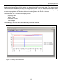
Figure 3-4 Main menu PPsolar
By double clicking on the name of an inverter, you will branch to submenus System Diagram, Control
Panel, Oscilloscope, Process Data, Data Storage, etc. Double click on one of these to open the relevant
window.
The System Diagram (Figure 3-5) shows the entire PV plant, including the PV generator, DC contactor,
inverter, AC contactor and grid interface. The status of the system components and the energy flow
within the system are represented by different colors in the diagram.
17
















![General design guidance [PDF 950KB]](http://vs1.manualzilla.com/store/data/005804077_1-5fec14441b6361d04901f77e13b8a9c0-150x150.png)