1
M095/M096/M099/M100
SERVICE MANUAL
It is the reader's responsibility when discussing the information contained
within this document to maintain a level of confidentiality that is in the best
interest of Ricoh Americas Corporation and its member companies.
NO PART OF THIS DOCUMENT MAY BE REPRODUCED IN ANY
FASHION AND DISTRIBUTED WITHOUT THE PRIOR
PERMISSION OF RICOH AMERICAS CORPORATION.
All product names, domain names or product illustrations, including
desktop images, used in this document are trademarks, registered
trademarks or the property of their respective companies.
They are used throughout this book in an informational or editorial fashion
only and for the benefit of such companies. No such use, or the use of
any trade name, or web site is intended to convey endorsement or other
affiliation with Ricoh products.
© 2011 RICOH Americas Corporation. All rights reserved.
WARNING
The Service Manual contains information
regarding service techniques, procedures,
processes and spare parts of office equipment
distributed by Ricoh Americas Corporation.
Users of this manual should be either service
trained or certified by successfully completing a
Ricoh Technical Training Program.
Untrained and uncertified users utilizing
information contained in this service manual to
repair or modify Ricoh equipment risk personal
injury, damage to property or loss of warranty
protection.
Ricoh Americas Corporation
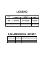
LEGEND
COMPANY
PRODUCT
CODE
LANIER
RICOH
SAVIN
M095
SPC240DN
Aficio SPC240DN
SPC240DN
M096
SPC242DN
Aficio SPC242DN
SPC242DN
M099
SPC240SF
Aficio SPC240SF
SPC240SF
M100
SPC242SF
Aficio SPC242SF
SPC242SF
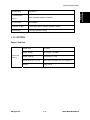
DOCUMENTATION HISTORY
REV. NO.
*
DATE
11/2011
COMMENTS
Original Printing
M095/M096/M099/M100
TABLE OF CONTENTS
1. PRODUCT INFORMATION .......................................................... 1-1 1.1 GENERAL SPECIFICATIONS ................................................................... 1-1 1.2 SUPPORTED PAPER SIZES .................................................................... 1-1 1.3 MACHINE OVERVIEW .............................................................................. 1-2 1.3.1 COMPONENT LAYOUT ................................................................... 1-2 Engine (M095/M096) ............................................................................ 1-2 Engine (M099/M100) ............................................................................ 1-3 ADF (only for M099/M100) ................................................................... 1-4 Scanner (only for M099/M100) ............................................................. 1-4 1.3.2 PAPER PATH ................................................................................... 1-5 ADF (only for M099/M100) ................................................................... 1-5 1.3.3 DRIVE LAYOUT ............................................................................... 1-6 1.4 MACHINE CONFIGURATION ................................................................... 1-8 1.4.1 PRINTER MODEL (M095/M096) ...................................................... 1-8 1.4.2 MF MODEL (M099/M100)................................................................. 1-8 1.5 GUIDANCE FOR THOSE WHO ARE FAMILIAR WITH PREDECESSOR
PRODUCTS ..................................................................................................... 1-9 2. INSTALLATION ............................................................................ 2-1 2.1 INSTALLATION REQUIREMENTS............................................................ 2-1 2.1.1 ENVIRONMENT ............................................................................... 2-1 2.1.2 MACHINE LEVEL ............................................................................. 2-1 2.1.3 MACHINE SPACE REQUIREMENT ................................................. 2-2 Printer Model ........................................................................................ 2-2 MF Model ............................................................................................. 2-2 2.1.4 POWER REQUIREMENTS .............................................................. 2-3 2.1.5 INSTALLATION PROCEDURE ........................................................ 2-3 3. PREVENTIVE MAINTENANCE .................................................... 3-3 3.1 PREVENTIVE MAINTENANCE ................................................................. 3-3 4. REPLACEMENT AND ADJUSTMENT ........................................ 4-1 4.1 BEFORE YOU START ............................................................................... 4-1 4.1.1 GENERAL PRECAUTIONS .............................................................. 4-1 SM
i
M095/M096/M099/M100
AIO ....................................................................................................... 4-1 Laser Unit ............................................................................................. 4-2 Transfer Roller ..................................................................................... 4-2 Fusing .................................................................................................. 4-2 Paper Feed .......................................................................................... 4-2 Scanner Unit (for M099/M100) ............................................................. 4-2 4.1.2 RELEASING PLASTIC LATCHES .................................................... 4-3 4.1.3 AFTER SERVICING THE MACHINE ................................................ 4-3 4.1.4 LITHIUM BATTERIES (MF MODELS) .............................................. 4-3 4.2 SPECIAL TOOLS....................................................................................... 4-4 4.3 EXTERIOR COVERS ................................................................................ 4-5 4.3.1 REAR COVER .................................................................................. 4-5 4.3.2 OPERATION PANEL ........................................................................ 4-6 4.3.3 RIGHT COVER ................................................................................. 4-7 4.3.4 LEFT COVER ................................................................................... 4-8 4.3.5 FRONT COVER UNIT ...................................................................... 4-9 4.4 LASER OPTICS ....................................................................................... 4-10 4.4.1 CAUTION DECAL LOCATIONS ..................................................... 4-10 4.4.2 LASER OPTICS HOUSING UNIT ................................................... 4-11 After replacing the laser optics housing unit ....................................... 4-14 Printing out the test chart to make sure MUSIC was performed correctly4-14 Checking that MUSIC was Performed Correctly ................................ 4-16 If MUSIC has not been performed successfully ................................. 4-17 4.5 AIO CARTRIDGE ..................................................................................... 4-18 4.5.1 AIO CARTRIDGE (ALL IN ONE CARTRIDGE) .............................. 4-18 4.5.2 BLACK AIO MOTOR....................................................................... 4-19 4.5.3 COLOR AIO MOTOR...................................................................... 4-22 4.6 IMAGE TRANSFER ................................................................................. 4-23 4.6.1 IMAGE TRANSFER BELT UNIT ..................................................... 4-23 After replacing the image transfer belt unit ......................................... 4-24 4.6.2 ITB (IMAGE TRANSFER BELT) CLEANING UNIT......................... 4-25 4.6.3 AGITATOR MOTOR ....................................................................... 4-26 4.6.4 ITB (IMAGE TRANSFER BELT) CONTACT MOTOR..................... 4-28 4.6.5 ITB (IMAGE TRANSFER BELT) CONTACT SENSOR ................... 4-29 4.6.6 TM (TONER MARK) SENSOR BASE ............................................. 4-30 4.6.7 WASTE TONER BOTTLE SET SENSOR....................................... 4-31 4.6.8 WASTE TONER OVERFLOW SENSOR ........................................ 4-32 4.7 PAPER TRANSFER ................................................................................ 4-33 M095/M096/M099/M100
ii
SM
4.7.1 TRANSFER UNIT ........................................................................... 4-33 4.7.2 TRANSFER ROLLER ..................................................................... 4-34 4.7.3 REGISTRATION ROLLER .............................................................. 4-36 Reassembling the registration roller unit ............................................ 4-36 4.7.4 REGISTRATION SENSOR ............................................................. 4-37 4.7.5 REGISTRATION CLUTCH ............................................................. 4-38 4.8 IMAGE FUSING ....................................................................................... 4-39 4.8.1 FUSING UNIT ................................................................................. 4-39 4.8.2 FUSING LAMP ............................................................................... 4-41 When Reinstalling the Fusing Lamp ................................................... 4-43 When Reassembling the Fusing Unit ................................................. 4-44 4.8.3 TRANSPORT/FUSING MOTOR ..................................................... 4-45 4.9 PAPER FEED .......................................................................................... 4-47 4.9.1 PAPER FEED CLUTCH.................................................................. 4-47 4.9.2 PAPER FEED ROLLER .................................................................. 4-48 4.9.3 SEPARATION PAD ........................................................................ 4-49 4.9.4 PAPER END SENSOR ................................................................... 4-50 4.10 PAPER EXIT ...................................................................................... 4-51 4.10.1 PAPER EXIT ROLLER ............................................................... 4-51 4.10.2 PAPER EXIT SENSOR .............................................................. 4-53 4.11 ELECTRICAL COMPONENTS .......................................................... 4-54 4.11.1 CONTROLLER BOARD ............................................................. 4-54 GDI/ PCL Controller Board (Printer Models) ...................................... 4-54 Controller Board (MF Models) ............................................................ 4-56 4.11.2 EGB (ENGINE BOARD) ............................................................. 4-58 Printer Models .................................................................................... 4-58 MF Models ......................................................................................... 4-60 4.11.3 FCU (ONLY FOR MF MODELS) ................................................ 4-62 4.11.4 4.11.5 4.11.6 4.11.7 4.11.8 4.11.9 INTERLOCK SWITCHES ........................................................... 4-63 FUSING FAN MOTOR ................................................................ 4-64 FUSING STRIPPER PAWL SOLENOID ..................................... 4-65 FUSING PRESSURE RELEASE SENSOR ................................ 4-67 LSU FAN MOTOR ...................................................................... 4-68 ID CHIP BOARD ......................................................................... 4-69 4.11.10 PSU .......................................................................................... 4-70 Fuse ................................................................................................... 4-73 4.11.11 HIGH VOLTAGE POWER SUPPLY BOARD............................ 4-73 4.11.12 TEMPERATURE/HUMIDITY SENSOR .................................... 4-74 SM
iii
M095/M096/M099/M100
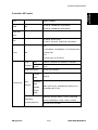
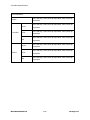
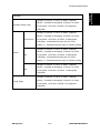
4.11.13 DUPLEX MOTOR ..................................................................... 4-74 4.11.14 SPEAKER (ONLY FOR MF MODELS) ..................................... 4-76 4.11.15 EEPROM .................................................................................. 4-77 Checking that MUSIC was Performed Correctly ................................ 4-78 4.12 ADF (ONLY FOR MF MODELS) ........................................................ 4-79 4.12.1 ADF UNIT ................................................................................... 4-79 4.12.2 ORIGINAL TRAY ........................................................................ 4-80 4.12.3 ADF FEED UNIT......................................................................... 4-81 4.12.4 ADF SEPARATION PAD ............................................................ 4-81 4.12.5 ADF FRONT COVER ................................................................. 4-82 4.12.6 ADF REAR COVER .................................................................... 4-82 4.12.7 ADF COVER ............................................................................... 4-83 4.12.8 ADF MOTOR .............................................................................. 4-84 4.12.9 ORIGINAL SET SENSOR........................................................... 4-86 4.12.10 ADF COVER OPEN SENSOR.................................................. 4-87 4.12.11 ADF FEED SENSOR ................................................................ 4-88 4.12.12 ADF DRIVE BOARD ................................................................. 4-89 4.13 SCANNER (ONLY FOR MF MODELS) .............................................. 4-90 4.13.1 SCANNER UNIT ......................................................................... 4-90 4.13.2 SCANNER TOP COVER ............................................................ 4-92 4.13.3 SCANNER CARRIAGE UNIT ..................................................... 4-93 4.13.4 EXPOSURE LAMP ..................................................................... 4-95 When reinstalling the exposure lamp ................................................. 4-96 4.13.5 LAMP STABILIZER BOARD ....................................................... 4-96 4.13.6 SCANNER MOTOR .................................................................... 4-97 5. SYSTEM MAINTENANCE REFERENCE..................................... 5-1 5.1 IMAGE PROBLEMS .................................................................................. 5-1 5.1.1 OVERVIEW ...................................................................................... 5-1 5.1.2 IMAGE PROBLEM ............................................................................ 5-1 5.2 ERROR CODES ........................................................................................ 5-2 5.2.1 OVERVIEW ...................................................................................... 5-2 5.2.2 ERROR CODES LIST....................................................................... 5-2 5.3 SERVICE CALL CONDITIONS .................................................................. 5-6 5.3.1 SUMMARY ....................................................................................... 5-6 5.3.2 ENGINE SC ...................................................................................... 5-7 SC 1xx (Other Error) ............................................................................ 5-7 SC 2xx (Laser Optics Error) ................................................................. 5-8 SC 3xx (Charge Error)........................................................................ 5-10 M095/M096/M099/M100
iv
SM
SC 4xx (Image Transfer and Transfer Error) ...................................... 5-11 SC 5xx (Motor and Fusing Error) ....................................................... 5-13 SC 6xx (Communication and Other Error).......................................... 5-18 5.3.3 CONTROLLER SC ......................................................................... 5-19 SC8xx................................................................................................. 5-19 5.4 SERVICE MENU...................................................................................... 5-21 5.4.1 OVERVIEW .................................................................................... 5-21 5.4.2 MAINTENANCE MODE MENU ...................................................... 5-22 Menu List............................................................................................ 5-22 5.4.3 FAX SERVICE TEST MENU (ONLY FOR MF MODELS)............... 5-35 Entering the Fax Service Test Menu .................................................. 5-35 Selecting an Item ............................................................................... 5-35 Going into the Next Level/ Returning to the Previous Level ............... 5-35 Exiting the Maintenance Mode Menu ................................................. 5-35 Menu List............................................................................................ 5-35 5.5 CONFIGURATION, MAINTENANCE AND TEST PAGE INFORMATION 5-37 5.5.1 OVERVIEW .................................................................................... 5-37 To Print the Configuration Page from the Machine (Printer models) .. 5-37 To Print the Test Page from the Machine (only for Printer Models) .... 5-37 To Print the Maintenance Page (Printer models) ............................... 5-37 To Print the Configuration Page/ Maintenance Page (MF models) .... 5-38 5.5.2 ERROR LOG .................................................................................. 5-38 5.5.3 COUNTER AND COVERAGE (ONLY FOR PRINTER MODELS) .. 5-39 Configuration Page ............................................................................ 5-39 5.6 FIRMWARE UPDATING .......................................................................... 5-40 5.6.1 CHECKING THE MACHINE FIRMWARE VERSION ...................... 5-40 5.6.2 UPDATING THE CONTROLLER FIRMWARE ............................... 5-40 5.6.3 UPDATING THE ENGINE FIRMWARE .......................................... 5-42 5.6.4 BOOT LOADER FIRMWARE ......................................................... 5-43 6. ENVIRONMENTAL CONSERVATION ......................................... 6-1 6.1 ENERGY SAVING ..................................................................................... 6-1 6.1.1 ENERGY SAVER MODES ............................................................... 6-1 Timer Settings (Printer Models) ............................................................ 6-2 Timer Settings (MF Models) ................................................................. 6-2 Return to Stand-by Mode ..................................................................... 6-2 Recommendation ................................................................................. 6-3 6.2 PAPER SAVE ............................................................................................ 6-4 6.2.1 EFFECTIVENESS OF DUPLEX/COMBINE FUNCTION .................. 6-4 SM
v
M095/M096/M099/M100
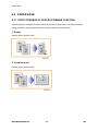
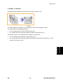
1. Duplex .............................................................................................. 6-4 2. Combine mode ................................................................................. 6-4 3. Duplex + Combine............................................................................ 6-5 M095/M096/M099/M100 SERVICE MANUAL APPENDICES
SEE M095/M096/M099/M100 SERVICE MANUAL APPENDICES SECTION FOR DETAILED
TABLE OF CONTENTS
PAPER FEED UNIT TYPE TK1010 (G849)
SEE SECTION G849 FOR DETAILED TABLE OF CONTENTS
M095/M096/M099/M100
vi
SM
READ THIS FIRST
Safety Notices
Important Safety Notices
Prevention of Physical Injury
1.
Before disassembling or assembling parts of the machine and peripherals, make sure that
the machine power cord is unplugged.
2.
The wall outlet should be near the machine and easily accessible.
3.
If any adjustment or operation check has to be made with exterior covers off or open while
the main switch is turned on, keep hands away from electrified or mechanically driven
components.
4.
The machine drives some of its components when it completes the warm-up period. Be
careful to keep hands away from the mechanical and electrical components as the machine
starts operation.
5.
The inside and the metal parts of the fusing unit become extremely hot while the machine is
operating. Be careful to avoid touching those components with your bare hands.
Health Safety Conditions
Toner is non-toxic, but if you get either of them in your eyes by accident, it may cause temporary
eye discomfort. Try to remove with eye drops or flush with water as first aid. If unsuccessful, get
medical attention.
Observance of Electrical Safety Standards
The machine and its peripherals must be serviced by a customer service representative who
has completed the training course on those models.
Safety and Ecological Notes for Disposal
1.
Do not incinerate toner bottles or used toner. Toner dust may ignite suddenly when
exposed to an open flame.
2.
Dispose of used toner, the maintenance unit which includes developer or the organic
photoconductor in accordance with local regulations. (These are non-toxic supplies.)
3.
Dispose of replaced parts in accordance with local regulations.
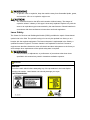
To prevent a fire or explosion, keep the machine away from flammable liquids, gases,
and aerosols. A fire or an explosion might occur.
The Controller board on the MF model contains a lithium battery. The danger of
explosion exists if a battery of this type is incorrectly replaced. Replace only with the
same or an equivalent type recommended by the manufacturer. Discard batteries in
accordance with the manufacturer's instructions and local regulations.
Laser Safety
The Center for Devices and Radiological Health (CDRH) prohibits the repair of laser-based
optical units in the field. The optical housing unit can only be repaired in a factory or at a
location with the requisite equipment. The laser subsystem is replaceable in the field by a
qualified Customer Engineer. The laser chassis is not repairable in the field. Customer
engineers are therefore directed to return all chassis and laser subsystems to the factory or
service depot when replacement of the optical subsystem is required.
Use of controls, or adjustment, or performance of procedures other than those
specified in this manual may result in hazardous radiation exposure.
WARNING
WARNING:
Turn off the main switch before attempting any of the procedures in the Laser Optics
Housing Unit section. Laser beams can seriously damage your eyes.
CAUTION MARKING:
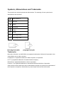
Symbols, Abbreviations and Trademarks
This manual uses several symbols and abbreviations. The meaning of those symbols and
abbreviations are as follows:
See or Refer to
Clip ring
Screw
Connector
Clamp
E-ring
SEF
Short Edge Feed
LEF
Long Edge Feed
Trademarks
Microsoft®, Windows®, and MS-DOS® are registered trademarks of Microsoft Corporation in the
United States and /or other countries.
PostScript® is a registered trademark of Adobe Systems, Incorporated.
PCL® is a registered trademark of Hewlett-Packard Company.
Ethernet® is a registered trademark of Xerox Corporation.
PowerPC® is a registered trademark of International Business Machines Corporation.
Other product names used herein are for identification purposes only and may be trademarks of
their respective companies. We disclaim any and all rights involved with those marks.
PRODUCT INFORMATION
R E V I S I O N H I S T O RY
P a ge
Date
A d de d /U pd at e d /N ew
None
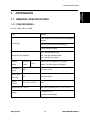
General Specifications
Product
Information
1. PRODUCT INFORMATION
1.1 GENERAL SPECIFICATIONS
See Appendices:
Appendices: Basic Specifications
Appendices: Controller Specifications
1.2 SUPPORTED PAPER SIZES
See Appendices:
SM
Appendices: Supported Paper Sizes
1-1
M095/M096/M099/M100
Machine Overview
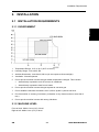
1.3 MACHINE OVERVIEW
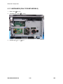
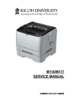
1.3.1 COMPONENT LAYOUT
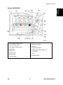
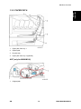
Engine (M095/M096)
1. Laser Optics Housing Unit
2. Print Cartridge (AIO)
3. Development Roller (AIO)
4. Paper Exit
5. Fusing Unit
6. Fusing Lamp
7. Duplex Path
8. Transfer Roller
M095/M096/M099/M100
9. Registration Roller
10. By-pass
11. Paper Feed Roller
12. ITB (Image Transfer Belt) Unit
13. OPC (AIO)
14. Tray 1
15 EGB/Controller
1-2
SM
Machine Overview
Product
Information
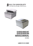
Engine (M099/M100)
1. Laser Optics Housing Unit
2. Print Cartridge (AIO)
3. Development Roller (AIO)
4. Paper Exit
5. Fusing Unit
6. Fusing Lamp
7. Duplex Path
8. Transfer Roller
SM
9. Registration Roller
10. By-pass
11. Paper Feed Roller
12. ITB (Image Transfer Belt) Unit
13. OPC (AIO)
14. Tray 1
15 EGB/Controller
1-3
M095/M096/M099/M100
Machine Overview
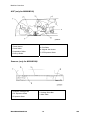
ADF (only for M099/M100)
1. Feed Sensor
2. Feed Roller
3. Separation Roller
4. Pick-up Roller
5. Exit Roller
6. Original Set Sensor
7. DF Exposure Glass
Scanner (only for M099/M100)
1. Scanner Carriage Unit
2. DF Exposure Glass
3. Exposure Glass
M095/M096/M099/M100
4. Carriage Drive Bar
5. White Plate
1-4
SM
Machine Overview
Product
Information
1.3.2 PAPER PATH
1.
Paper path from tray 1
2.
Duplex path
3.
By-pass tray
4.
Paper path from tray 2 (optional)
ADF (only for M099/M100)
1.
SM
Original path
1-5
M095/M096/M099/M100
Machine Overview
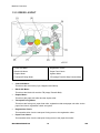
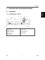
1.3.3 DRIVE LAYOUT
1. Color AIO Motor
5. Registration Clutch
2. Black AIO Motor
6. Paper Feed Clutch
3. Duplex Motor
7. Agitator Motor
4. Transport/Fusing Motor
8. ITB (Image Transfer Belt) Contact Motor
Color AIO Motor:
This drives the color AIOs (Cyan, Magenta and Yellow)
Black AIO Motor:
This drives the black AIO and the ITB (Image Transfer Belt).
Duplex Motor :
This drives the paper exit roller and the duplex roller.
Transport/Fusing Motor:
This drives the fusing unit, paper feed roller, registration roller and paper exit roller via the
paper feed clutch, registration clutch and gears.
Registration Clutch:
This transfers drive from the transport/ fusing motor to the registration roller.
Paper Feed Clutch:
This transfers drive from the transport/ fusing motor to the paper feed roller.
M095/M096/M099/M100
1-6
SM
Machine Overview
Agitator Motor:
Product
Information
This moves the agitators in the waste toner bottle.
ITB Contact Motor:
This moves the ITB into contact with and away from the color OPCs.
SM
1-7
M095/M096/M099/M100
Machine Configuration
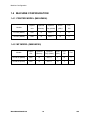
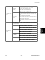
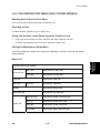
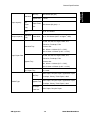
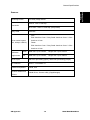
1.4 MACHINE CONFIGURATION
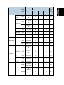
1.4.1 PRINTER MODEL (M095/M096)
Duplex
Optional
Optional
DDST
PCL
Unit
Memory
Tray (G849)
(GDI)
PS
PE-P2a (M095)
Auto
N
500 x 1
Y
N
PE-P2c (M096)
Auto
N
500 x 1
N
Y
Models
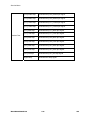
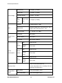
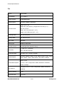
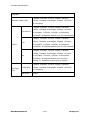
1.4.2 MF MODEL (M099/M100)
Duplex
Optional
Optional
DDST
PCL
Unit
Memory
Tray (G849)
(GDI)
PS
PE-MF3a (M099)
Auto
N
500 x 1
Y
N
Y
PE-MF3c (M100)
Auto
N
500 x 1
N
Y
Y
Models
M095/M096/M099/M100
1-8
Fax
SM
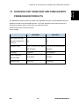
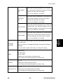
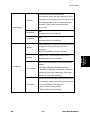
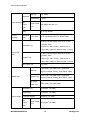
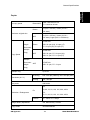
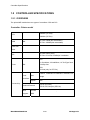
1.5 GUIDANCE FOR THOSE WHO ARE FAMILIAR WITH
PREDECESSOR PRODUCTS
The M095/M096 series models are similar to the M035/M036 series, and the M099/M100 series
models are similar to the M018/M019 series. If you have experience with those products, the
following information will be of help when you read this manual.
Different Points from Previous Products
Printer models:
M095/M096
M035/M036
New Fusing Unit that
improves maintenance
Yes
No
efficiency
Operation Panel
Pictbridge
Smart Organizing
Monitor (SOM)
Warm-up Time
SM
2-line LCD and 3 high visibility 2-line LCD and standard LED
LED indicators
indicators
Supported
Not supported
Not required
Required
30 seconds
48 seconds
1-9
M095/M096/M099/M100
Product
Information
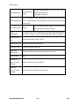
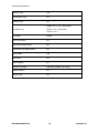
Guidance for Those Who are Familiar with Predecessor Products
Guidance for Those Who are Familiar with Predecessor Products
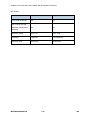
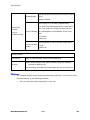
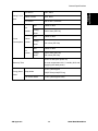
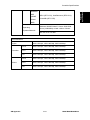
MF models:
M099/M100
Front USB Connector
M018/M019
Yes
No
Yes
No
Operation Panel
4-line LCD
2-line LCD
Pictbridge
Supported
Not supported
Warm-up Time
30 seconds
48 seconds
New Fusing Unit that
improves maintenance
efficiency
M095/M096/M099/M100
1-10
SM
INSTALLATION
R E V I S I O N H I S T O RY
P a ge
Date
A d de d /U pd at e d /N ew
None
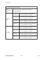
Installation Requirements
2. INSTALLATION
2.1 INSTALLATION REQUIREMENTS
Installation
2.1.1 ENVIRONMENT
1.
Temperature Range: 10°C to 32°C (50°F to 89.6°F)
2.
Humidity Range: 15% to 80% RH
3.
Ambient Illumination: Less than 2,000 lux (do not expose to direct sunlight)
4.
Ventilation: 3 times/hr/person
5.
Do not put the machine in areas that get sudden temperature changes. This includes:
Areas directly exposed to cool air from an air conditioner
Areas directly exposed to heat from a heater.
6.
Do not put the machine in areas that get exposed to corrosive gas.
7.
Do not install the machine at locations over 2,000 m (6,560 ft.) above sea level.
8.
Put the machine on a strong, level base. (Inclination on any side must be no more than 5
mm.)
9.
Do not put the machine in areas with strong vibrations.
2.1.2 MACHINE LEVEL
Front to back: Within 5 mm (0.2") of level
Right to left: Within 5 mm (0.2") of level
SM
2-1
M095/M096/M099/M100
Installation Requirements
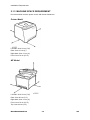
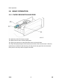
2.1.3 MACHINE SPACE REQUIREMENT
Put the machine near the power source with these clearances:
Printer Model
Left side: Over 20 cm (7.9")
Rear: Over 10 cm (4")
Right side: Over 10 cm (4")
Front: Over 70 cm (27.5")
MF Model
Left side: Over 20 cm (7.9")
Rear: Over 20 cm (7.9")
Right side: Over 10 cm (4")
Front: Over 70 cm (27.5")
Top: Over 24 cm (9.5")
M095/M096/M099/M100
2-2
SM
Installation Requirements
Make sure that the plug is tightly in the outlet.
Avoid multi-wiring.
Make sure that you ground the machine.
120 V, 60 Hz: More than 11 A (for North America)
Input voltage level
220 V to 240 V, 50 Hz/60 Hz: More than 6 A (for Europe/ Asia)
110 V, 60 Hz: More than 12 A (for Taiwan)
Permitted voltage fluctuation: 10%
Do not set anything on the power cord.
2.1.5 INSTALLATION PROCEDURE
Refer to the Quick Installation Guide for details about installing the machine.
SM
2-3
M095/M096/M099/M100
Installation
2.1.4 POWER REQUIREMENTS
PREVENTIVE MAINTENANCE
R E V I S I O N H I S T O RY
P a ge
Date
A d de d /U pd at e d /N ew
None
Preventive Maintenance
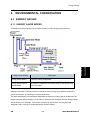
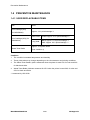
3. PREVENTIVE MAINTENANCE
3.1 PREVENTIVE MAINTENANCE
Preventive
Maintenance
See "Appendices" for the "User Replaceable Items".
SM
3-3
M095/M096/M099/M100
REPLACEMENT AND ADJUSTMENT
R E V I S I O N H I S T O RY
P a ge
Date
A d de d /U pd at e d /N ew
None
Before You Start
4. REPLACEMENT AND ADJUSTMENT
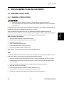
4.1 BEFORE YOU START
4.1.1 GENERAL PRECAUTIONS
If there are printer jobs in the machine, print out all jobs in the printer buffer.
Turn off the main power switch and unplug the machine before you do the procedures
in this section.
Use extreme caution when removing and replacing components. The cables in the machine are
located very close to moving parts; proper routing is a must.
procedure must be restored as close as possible to their original positions. Before removing any
component from the machine, note any cable routings that may be affected.
Before servicing the machine:
1.
Verify that documents are not stored in memory.
2.
Remove the print cartridge before you remove parts.
3.
Unplug the power cord.
4.
Work on a flat and clean surface.
5.
Replace with authorized components only.
6.
Do not force plastic material components.
Make sure all components are returned to their original positions.
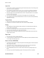
AIO
The AIO consists of the OPC drum, charge roller, development unit, cleaning components and
toner tank. Observe the following precautions when handling the AIO.
1.
Never touch the drum surface with bare hands. If the drum surface is dirty or if you have
accidentally touched it, wipe it with a dry cloth, or clean it with wet cotton and then wipe it
dry with a cloth.
2.
Never use alcohol to clean the drum. Alcohol will dissolve the drum surface.
3.
Store the AIO in a cool dry place.
4.
Do not expose the drum to corrosive gases (ammonia, etc.).
5.
Do not shake a used AIO, as this may cause toner to spill out.
6.
Dispose of used AIO components in accordance with local regulations.
SM
4-1
M095/M096/M099/M100
Replacement
and
Adjustment
After components have been removed, any cables that have been displaced during the
Before You Start
Laser Unit
1.
Do not loosen or adjust the screws securing the LD drive board on the LD unit. Doing so will
throw the LD unit out of adjustment.
2.
Do not adjust the variable resistors on the LD unit, as these are permanently adjusted at
the factory. If replacement of the LD drive board is necessary, replace the entire LD unit.
3.
Keep the polygon mirror and toroidal lens free of dust. Laser performance is very sensitive
to dust on these components.
4.
Do not touch the shield glass or the surface of the polygon mirror with bare hands.
5.
Do not adjust the Laser Synchronization detector on the LD unit, as these are permanently
adjusted at the factory.
Transfer Roller
1.
Never touch the surface of the transfer roller with bare hands.
2.
Be careful not to scratch the transfer roller, as the surface is easily damaged.
Fusing
1.
After installing the fusing thermistor, make sure that it is in contact with the hot roller and
that the roller can rotate freely.
2.
Be careful to avoid damage to the hot roller stripper pawls and their tension springs.
3.
Do not touch the fusing lamp and rollers with bare hands.
4.
Make sure that the fusing lamp is positioned correctly and that it does not touch the inner
surface of the hot roller.
Paper Feed
1.
Do not touch the surface of paper feed rollers.
2.
To avoid misfeeds, the side and end fences in each paper tray must be positioned correctly
so as to align with loaded paper size.
Scanner Unit (for M099/M100)
1.
Use alcohol or glass cleaner to clean the exposure and scanning glass. This will reduce the
static charge on the glass.
2.
Use a blower brush or a water-moistened cotton pad to clean the mirrors and lenses.
3.
Make sure to not bend or crease the exposure lamp’s ribbon cable.
4.
Do not disassemble the lens unit. This will cause the lens and copy image to get out of
focus.
5.
Do not turn any of the LED positioning screws. This will put the LED out of position.
M095/M096/M099/M100
4-2
SM
Before You Start
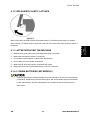
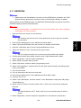
4.1.2 RELEASING PLASTIC LATCHES
Many of the parts are held in place with plastic latches. The latches break easily, so release
them carefully. To release a latch, press the hook end of the latch away from the part to which it
Replacement
and
Adjustment
is latched.
4.1.3 AFTER SERVICING THE MACHINE
1.
Make sure all parts that require grounding are properly grounded.
2.
Make sure the interlock switch is functioning.
3.
Do not leave unused solder or parts inside the machine.
4.
Do not leave any tools inside the machine.
5.
Make sure all wires are properly connected and routed.
6.
Make sure wires are not jammed between parts of the machine.
4.1.4 LITHIUM BATTERIES (MF MODELS)
Incorrect replacement of lithium battery(s) on the controller or on the fax unit poses risk
of explosion. Replace only with the same type or with an equivalent type recommended
by the manufacturer. Discard used batteries in accordance with the manufacturer’s
instructions.
SM
4-3
M095/M096/M099/M100
Special Tools
4.2 SPECIAL TOOLS
PC: Windows 2000/XP/Vista/7 or Windows Server 2003/2003 R2.
USB cable or Crossover cable
M095/M096/M099/M100
4-4
SM
Exterior Covers
4.3 EXTERIOR COVERS
Turn off the main power switch and unplug the printer before you do the procedures in
this section.
Replacement
and
Adjustment
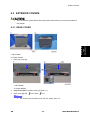
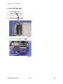
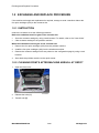
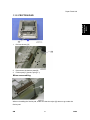
4.3.1 REAR COVER
1: MF models
2: Printer models
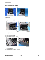
1.
Rear tray cover [A]
1: MF Models
2: Printer Models
2.
Only for Printers: Interface cover [C] (hook x 1)
3.
Rear cover [B] (MF:
SM
x 2 Printer:
x 3)
The screw in the Interface cover: M3 x 8, others: M4 x 10
4-5
M095/M096/M099/M100
Exterior Covers
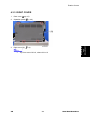
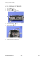
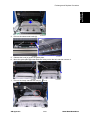
4.3.2 OPERATION PANEL
1: MF Models
2: Printer Models
1.
Open the top cover [A].
1:
MF Models
2:
Printer Models
2.
Open the front cover [B].
3.
Front harness cover [C] (
x 1)
1: MF Models
2: Printer Models
4.
Operation panel [D] (
M095/M096/M099/M100
x 1,
x 1)
4-6
SM
Exterior Covers
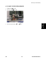
4.3.3 RIGHT COVER
Rear cover (
2.
Operation panel (
3.
Right cover [A] (
SM
p.4-5)
p.4-6)
Replacement
and
Adjustment
1.
x 4)
Top front screw: M3 x 8, others: M4 x 10
4-7
M095/M096/M099/M100
Exterior Covers
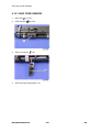
4.3.4 LEFT COVER
1.
Open the front cover.
2.
Open the top cover.
3.
Left cover [A] (
x 3, hook at the arrow mark above)
Top front screw: M3 x 8, others: M4 x 10
Remove the rear panel and the operation panel in advance when you meet
difficulties in removing the left cover.
M095/M096/M099/M100
4-8
SM
Exterior Covers
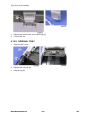
4.3.5 FRONT COVER UNIT
1.
Rear cover (
2.
Operation panel (
3.
Transfer unit (
4.
Right cover (
5.
Cover link gear unit [A] (
6.
Release the belt [B]
7.
Front cover unit [C] (
SM
p.4-5)
p.4-6)
p.4-33)
Replacement
and
Adjustment
p.4-7)
x 2)
x 4)
4-9
M095/M096/M099/M100
Laser Optics
4.4 LASER OPTICS
Turn off the main power switch and unplug the printer before beginning any of the
procedures in this section. Laser beams can cause serious eye injury.
4.4.1 CAUTION DECAL LOCATIONS
Caution decals are attached as shown below.
Be sure to turn off the main power switch and disconnect the power plug from the
power outlet before beginning any disassembly or adjustment of the laser unit. This
printer uses a class IIIb laser beam with a wavelength of 655 nm and an output of 7
mW. The laser can cause serious eye injury.
M095/M096/M099/M100
4-10
SM
Laser Optics
4.4.2 LASER OPTICS HOUSING UNIT
1.
Rear cover (
2.
Controller box cover (
3.
MF model only: Remove the controller bracket (
4.
Disconnect the three harnesses from CN301, 302 and 303 on the EGB (
5.
Open the top cover [A].
SM
p.4-5)
p.4-54)
4-11
x 3).
M095/M096/M099/M100
Replacement
and
Adjustment
p.4-58)
Laser Optics
6.
Lift up the hook [B] of the harness guide at the rear-left frame and slide the harness guide to
the right.
x 2 each; left side and right side)
7.
Stoppers [C] (
8.
Remove the springs [D] (left side and right side).
9.
Remove the laser optics housing unit [E] from the top cover and place it on the main body.
Always use two hands when carrying the laser optics housing unit. Be sure not to
drop the laser optics housing unit.
M095/M096/M099/M100
4-12
SM
Laser Optics
x 1).
Replacement
and
Adjustment
10. Take out the harnesses [F] (
11. Remove the laser optics housing unit.
SM
4-13
M095/M096/M099/M100
Laser Optics
After replacing the laser optics housing unit
1.
Open the front cover and turn on the machine.
Do the following 2 steps with the front cover of the machine open.
On the LCD, access “LSU Adjustment” inside the “Engine Maintenance” menu.
Manually input the corresponding LSU data from your supervisor into the space
provided on the LCD.
2.
Close the front cover.
3.
Perform “Color Registration” in the “Engine Maintenance” menu.
4.
Turn the power off and on.
5.
MUSIC will be performed automatically.
Print out the test chart (
Test Chart), and make sure that MUSIC was performed
successfully (see ‘Printing out the Test Chart” and ‘Checking that MUSIC was Performed
Correctly’ below).
6.
If necessary, adjust the registration settings for each tray and for the front and rear sides of
the paper with the "Engine Maintenance" menu.
When the MUSIC error persists, contact your supervisor, and get a set of LD
parameters for the unit. After that, enter them with “LSU Adjustment” in the
Maintenance Mode Menu (
“If MUSIC has not been performed successfully”
below).
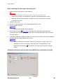
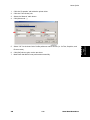
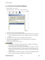
Printing out the test chart to make sure MUSIC was performed correctly
M095/M096/M099/M100
4-14
SM
1.
Click the “Properties” tab inside the printer driver.
2.
Click the “Print Quality” tab.
3.
Select the “Manual” radio button.
4.
Click [Advanced…].
5.
Select “Off” for the three Color Profile pull-down menus shown (i.e. for Text, Graphics, and
Photo modes).
6.
Click [OK] twice to print out the test chart.
7.
Make sure that MUSIC was performed successfully.
SM
4-15
M095/M096/M099/M100
Replacement
and
Adjustment
Laser Optics
Laser Optics
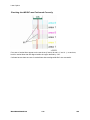
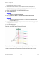
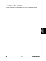
Checking that MUSIC was Performed Correctly
Four sets of vertical lines appear on the test chart (C and k, M and k, Y and k…). In each set,
look for vertical lines that are aligned within the region defined by “OK”.
If all sets have at least one set of vertical lines that are aligned MUSIC was successful.
M095/M096/M099/M100
4-16
SM
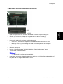
Laser Optics
1.
Open the upper cover and check the lot number of the laser optics housing unit.
2.
Contact your supervisor, and get the LD parameters for this lot number [A].
3.
Open the front cover and turn on the machine.
4.
Program the settings for the laser optics housing unit.
On the LCD, access “LSU Adjustment” inside the “Engine Maintenance” menu.
Manually input the corresponding LSU data from your supervisor into the space
provided on the LCD.
5.
Close the front cover.
6.
Execute “Color Registration”, which is inside the “Engine Maintenance” menu.
7.
Turn the main power Off and On.
8.
MUSIC will be performed automatically.
If necessary, adjust the registration settings for each tray and for the front and rear sides of
the paper with the "Engine Maintenance" menu.
SM
4-17
M095/M096/M099/M100
Replacement
and
Adjustment
If MUSIC has not been performed successfully
AIO Cartridge
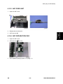
4.5 AIO CARTRIDGE
4.5.1 AIO CARTRIDGE (ALL IN ONE CARTRIDGE)
1.
Open the top cover.
2.
AIO cartridge [A]
M095/M096/M099/M100
4-18
SM
AIO Cartridge
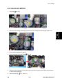
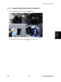
4.5.2 BLACK AIO MOTOR
Left cover (
p.4-8)
2.
Disconnect the fusing connector [A] and remove the fusing relay harness [B] (hooks x 2).
3.
Fusing harness guide [C] (
4.
Fusing thermistor harness guide (
5.
Disconnect the connectors shown by arrows in the above picture and release all harnesses
Replacement
and
Adjustment
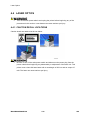
1.
x 2)
p.4-74)
on the harness guide [D].
6.
SM
Harness guide [D] (
x 4, hook x 1)
4-19
M095/M096/M099/M100
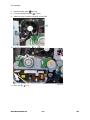
AIO Cartridge
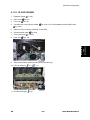
7.
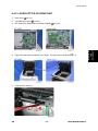
Interlock switch base (
8.
FCU and Speaker bracket (
9.
Disconnect the connector (CN305) on the EGB.
10. LSU fan motor base [E] (
11. Drive unit [F] (
p.4-63)
p.4-54)
x 2,
x 1)
x 4)
M095/M096/M099/M100
4-20
SM
AIO Cartridge
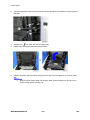
12. Drive unit guide [G] (
x 3)
13. Black AIO gear [H] (snap ring x 1)
Replacement
and
Adjustment
14. ITB gear [I] (snap ring x 1)
15. Black AIO motor [J] (
SM
x 3)
4-21
M095/M096/M099/M100
AIO Cartridge
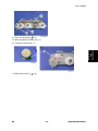
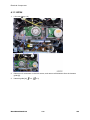
4.5.3 COLOR AIO MOTOR
1.
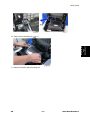
Drive unit (
p.4-19)
2.
Drive unit guide [A] (
3.
Color AIO gears [B] (ring stopper x 1)
4.
Color AIO motor [C] (
M095/M096/M099/M100
x 3)
x 3)
4-22
SM
Image Transfer
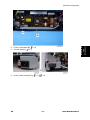
4.6 IMAGE TRANSFER
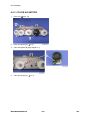
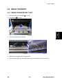
4.6.1 IMAGE TRANSFER BELT UNIT
1.
Remove all the AIO cartridges (
2.
Transfer unit (
3.
Pull out the waste toner bottle [A].
4.
Release the hook [B] under the guide plate.
5.
Move the guide plate [C] underneath the fusing unit to the left, and then remove it
SM
p.4-18).
Replacement
and
Adjustment
p.4-33)
4-23
M095/M096/M099/M100
Image Transfer
6.
Pull out the image transfer belt unit [D] (
x 2).
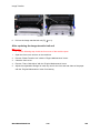
After replacing the image transfer belt unit
Do the following step 2 with the front cover of the machine open.
1.
Open the front cover and turn on the machine.
2.
Execute "Reset Transfer Unit” with the "Engine Maintenance" menu.
3.
Close the front cover.
4.
Execute "Trans. Belt Adjust" with the "Engine Maintenance" menu.
5.
Adjust the registration settings for each tray and for the front and rear sides of the paper
with the "Engine Maintenance" menu if necessary.
M095/M096/M099/M100
4-24
SM
Image Transfer
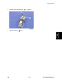
4.6.2 ITB (IMAGE TRANSFER BELT) CLEANING UNIT
The ITB cleaning unit contains waste toner. When removing the ITB cleaning unit, put it
on a sheet of paper.
Image transfer belt unit (
2.
Left handle [A] (hook, bushing x 1)
3.
Right handle [B] (hook, bushing x 1)
4.
ITB cleaning unit [C] (
SM
Replacement
and
Adjustment
p.4-23)
1.
x 2)
4-25
M095/M096/M099/M100
Image Transfer
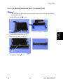
4.6.3 AGITATOR MOTOR
1.
Right cover (
p.4-7)
2.
Motor bracket [A] (
M095/M096/M099/M100
x 2)
4-26
SM
Image Transfer
3.
Agitator motor assembly [B] (
4.
Agitator motor [C] (
x 1,
x 1)
Replacement
and
Adjustment
x 2)
SM
4-27
M095/M096/M099/M100
Image Transfer
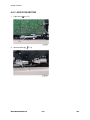
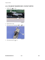
4.6.4 ITB (IMAGE TRANSFER BELT) CONTACT MOTOR
1.
Agitator motor (
2.
Release the wire [A].
3.
ITB contact motor assembly [B] (
4.
ITB contact motor [C] (
M095/M096/M099/M100
p.4-26)
x 1,
x 1)
x 2)
4-28
SM
Image Transfer
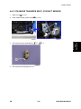
4.6.5 ITB (IMAGE TRANSFER BELT) CONTACT SENSOR
Right cover (
2.
High voltage power supply board (
p.4-73)
3.
ITB contact sensor assembly [A] (
x 1,
4.
ITB contact sensor [B] (hooks x 3)
SM
p.4-7)
4-29
Replacement
and
Adjustment
1.
x 1)
M095/M096/M099/M100
Image Transfer
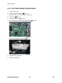
4.6.6 TM (TONER MARK) SENSOR BASE
1.
Open the top cover.
2.
Remove all AIO cartridges (
3.
Slide the ITB unit to the front side or remove it.
4.
Rear cover (
5.
Controller box cover (
6.
MF models only: FCU and Speaker bracket (
7.
Disconnect CN306 on the EGB (
8.
Harness cover [A] (hook)
9.
TM sensor base [B]
p.4-18).
p.4-5)
M095/M096/M099/M100
p.4-54)
p.4-58)
x 1).
4-30
SM
Image Transfer
4.6.7 WASTE TONER BOTTLE SET SENSOR
1.
Remove all AIO cartridges. (
2.
Image transfer belt unit (
3.
EGB (
4.
Remove two screws [A] for the waste toner sensor base.
SM
p.4-18)
p.4-23)
4-31
Replacement
and
Adjustment
p.4-58)
M095/M096/M099/M100
Image Transfer
5.
Waste toner sensor base [B]
6.
Waste toner bottle set sensor [C] (hooks x 3,
x 1)
When reinstalling the waste toner bottle set sensor, connect it to the white connector of
the harness.
4.6.8 WASTE TONER OVERFLOW SENSOR
1.
Remove all AIO cartridges. (
2.
Image transfer belt unit (
3.
EGB (
4.
Waste toner sensor base (
5.
Waste toner overflow sensor [A] (hooks x 3,
p.4-18)
p.4-23)
p.4-58)
p.4-31)
x 1)
When reinstalling the waste toner overflow sensor, connect it to the black connector of
the harness.
M095/M096/M099/M100
4-32
SM
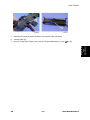
Paper Transfer
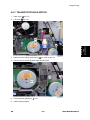
4.7 PAPER TRANSFER
4.7.1 TRANSFER UNIT
If you install a complete new unit, execute "Reset 2nd Transfer Unit" with the "Engine
Maintenance" menu, otherwise a paper transfer error may occur.
Open the front cover.
2.
Release the locks [A].
3.
Transfer unit [B]
4.
If you install a complete new unit, execute "Reset 2nd Transfer Unit" with the "Engine
Replacement
and
Adjustment
1.
Maintenance" menu (
SM
p.5-22).
4-33
M095/M096/M099/M100
Paper Transfer
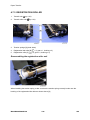
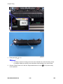
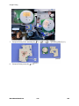
4.7.2 TRANSFER ROLLER
If you install a new roller, execute "Reset 2nd Transfer Unit" with the "Engine
Maintenance" menu, otherwise a paper transfer error may occur.
p.4-33)
1.
Transfer Unit (
2.
Release the two hooks [A] at both sides of the transfer unit.
3.
Open the transfer roller unit [B] and remove it.
4.
Transfer roller assembly [C] (
M095/M096/M099/M100
x 2)
4-34
SM
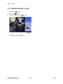
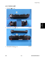
Paper Transfer
Release the holder [D] at the left side of the transfer roller unit (hook).
6.
Transfer roller [E]
7.
Execute "Reset 2nd Transfer Unit" with the "Engine Maintenance" menu (
p.5-22).
Replacement
and
Adjustment
5.
SM
4-35
M095/M096/M099/M100
Paper Transfer
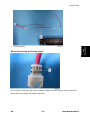
4.7.3 REGISTRATION ROLLER
1.
Transfer unit (
p.4-33)
2.
Transfer roller unit (
3.
Tension springs [A] (both sides)
4.
Registration idle roller [B] (
5.
Registration roller [C] (
p.4-34)
x 2, gear x 1, bushing x 2)
x 2, gear x 2, bushing x 2)
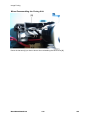
Reassembling the registration roller unit
When installing the tension spring, make sure that the tension spring correctly hooks onto the
bushing of the registration idle roller as shown above [A].
M095/M096/M099/M100
4-36
SM
Paper Transfer
4.7.4 REGISTRATION SENSOR
Right Cover (
p.4-7)
2.
Registration sensor assembly [A] (
3.
Registration sensor [B] (hooks)
x 1,
x 1)
Replacement
and
Adjustment
1.
SM
4-37
M095/M096/M099/M100
Paper Transfer
4.7.5 REGISTRATION CLUTCH
1.
Rear cover (
p.4-5)
2.
Left cover (
3.
Transport/Fusing motor (
4.
Registration clutch [A] (
p.4-8)
M095/M096/M099/M100
p.4-45)
x 1)
4-38
SM
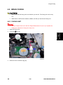
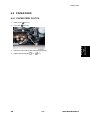
Image Fusing
4.8 IMAGE FUSING
Make sure that the fusing unit is cool before you touch it. The fusing unit can be very
hot.
Make sure to restore the insulators, shields, etc after you service the fusing unit.
4.8.1 FUSING UNIT
Execute "Reset Fuser Unit" with the "Engine Maintenance" menu if you replace the
fusing unit, otherwise a fusing error may occur.
1.
Open the front cover.
2.
Left cover (
3.
Disconnect the connectors [A], [B].
Replacement
and
Adjustment
p.4-8)
SM
4-39
M095/M096/M099/M100
Image Fusing
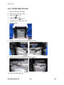
4.
Fusing unit [C] (
x 3)
It is likely to remove a fusing unit cover screw instead of the lower left fixing screw
by mistake. Make sure which screw should be removed before you do this step.
5.
Execute "Reset Fuser Unit" with the "Engine Maintenance" menu (
p.5-22) if the fusing
unit is replaced.
M095/M096/M099/M100
4-40
SM
Image Fusing
4.8.2 FUSING LAMP
Fusing unit (
2.
Fusing front cover [A] (
x 3)
3.
Fusing back cover [B] (
x 2)
SM
p.4-39)
Replacement
and
Adjustment
1.
4-41
M095/M096/M099/M100
Image Fusing
4.
Fusing lamp cable [C] (
5.
Lamp right stay [E] (
6.
Lamp left stay [D] (
M095/M096/M099/M100
x 2)
x 1)
x 1)
4-42
SM
7.
Replacement
and
Adjustment
Image Fusing
Fusing lamp [E]
When Reinstalling the Fusing Lamp
The end of the fusing lamp [A], which shows the voltage and power ratings, must be placed at
the left side of the fusing unit (fusing cable side).
SM
4-43
M095/M096/M099/M100
Image Fusing
When Reassembling the Fusing Unit
Route the harness [A] as shown above when reinstalling the back cover [B].
M095/M096/M099/M100
4-44
SM
Image Fusing
4.8.3 TRANSPORT/FUSING MOTOR
1.
Rear cover (
p.4-5)
2.
Left cover (
3.
Disconnect the fusing connector [A] (
4.
Pull out the connector [B] downward and remove it.
5.
Fusing harness guide [C] (
6.
Duplex timing belt [D]
Replacement
and
Adjustment
p.4-8)
SM
p.4-39, hooks x 2).
x 2)
4-45
M095/M096/M099/M100
Image Fusing
7.
Transport/Fusing motor assembly [E] (
8.
Transport/Fusing motor [G] (
M095/M096/M099/M100
x 3,
x 3,
x 1, grounding plate [F] x 1)
x 3)
4-46
SM
Paper Feed
4.9 PAPER FEED
4.9.1 PAPER FEED CLUTCH
1.
Rear cover (
2.
Left cover (
3.
Disconnect the fusing relay harness [A] (hook).
4.
Paper feed clutch [B] (
SM
p.4-5)
x 1,
Replacement
and
Adjustment
p.4-8)
x 1)
4-47
M095/M096/M099/M100
Paper Feed
4.9.2 PAPER FEED ROLLER
1.
Remove all the AIO cartridges.
2.
Remove the waste toner bottle.
3.
Rear cover (
4.
Left cover (
5.
Paper feed clutch (
6.
Close the top cover and front cover.
7.
Pull out the tray.
8.
Stand the machine with the rear side facing the table.
9.
Slide the paper feed shaft [A] to the left side (
p.4-5)
p.4-8)
p.4-47)
x 2).
10. Paper feed roller [B] (hook)
M095/M096/M099/M100
4-48
SM
Paper Feed
4.9.3 SEPARATION PAD
Pull out the tray.
2.
Push down the bottom plate [A].
3.
Separation pad [B] (hooks x 2, spring x 1)
Replacement
and
Adjustment
1.
When reinstalling the separation pad, make sure that the Mylar [C] is not placed under
the separation pad. The right side image above shows incorrect installation.
SM
4-49
M095/M096/M099/M100
Paper Feed
4.9.4 PAPER END SENSOR
1.
Rear cover (
p.4-5)
2.
Right cover (
p.4-7)
3.
High voltage power supply board (
4.
Paper end sensor assembly [A] (
5.
Paper end sensor [B] (hooks x 3)
M095/M096/M099/M100
p.4-73)
x 1)
4-50
SM
Paper Exit
4.10 PAPER EXIT
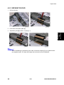
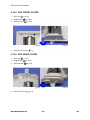
4.10.1 PAPER EXIT ROLLER
Operation panel (
p.4-6)
2.
Remove the bushing [A] (
3.
Pull out the paper exit roller [B] from the right stay, and move its left side towards the front
Replacement
and
Adjustment
1.
x 1)
slightly, and then remove it from the mainframe. (
SM
4-51
x 1)
M095/M096/M099/M100
Paper Exit
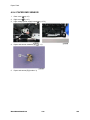
4.
Remove the four exit guides [C] and gear [D] (bushing x 1).
M095/M096/M099/M100
4-52
SM
Paper Exit
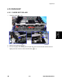
4.10.2 PAPER EXIT SENSOR
Rear cover (
p.4-5)
2.
Right cover (
p.4-7)
3.
Fusing pawl solenoid assembly [A] (
Replacement
and
Adjustment
1.
4.
The upper right screw in the above photo is different from other 3 screws.
Remove the paper exit sensor [C] while lightly pressing the feeler [B] in the direction shown
by the arrow (hooks x 4,
SM
x 4)
x 1).
4-53
M095/M096/M099/M100
Electrical Components
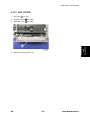
4.11 ELECTRICAL COMPONENTS
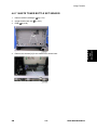
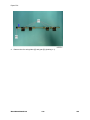
4.11.1 CONTROLLER BOARD
GDI/ PCL Controller Board (Printer Models)
1.
Rear cover (
p.4-5)
2.
Controller box cover [A] (
M095/M096/M099/M100
x 6)
4-54
SM
Replacement
and
Adjustment
Electrical Components
3.
Interface bracket [B] (
x 2)
1: GDI
2: PCL
4.
SM
GDI controller board [C] or PCL controller board [D] (
4-55
x 6,
x 1)
M095/M096/M099/M100
Electrical Components
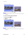
Controller Board (MF Models)
1.
Rear cover (
p.4-5)
2.
Controller box cover [A] (
3.
Interface bracket [B] (
M095/M096/M099/M100
x 7)
x 2)
4-56
SM
4.
Disconnect the flat cable with the Ferrite core [C] and remove it (
5.
Grounding screw [D] (
6.
FCU and Speaker bracket [E] (
7.
Controller board [F] (all
SM
x 1, hooks x 2).
x 1)
s,
x 5,
x 1,
x 2)
x 6)
4-57
M095/M096/M099/M100
Replacement
and
Adjustment
Electrical Components
Electrical Components
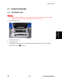
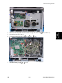
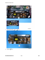
4.11.2 EGB (ENGINE BOARD)
Printer Models
1.
Rear cover (
2.
EGB [A] (
3.
EEPROM [B]
p.4-5)
x 6, all
s)
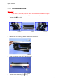
When installing the new EGB
1.
Remove the EEPROM from the old EGB.
M095/M096/M099/M100
4-58
SM
2.
Install it on the new EGB with the mark [A] pointing to the right side of the board after you
replace the EGB.
3.
Replace the EEPROM if the EEPROM on the old EGB is defective.
Keep the EEPROM away from objects that can cause static electricity. Static electricity
can damage EEPROM data.
SM
Make sure that the EEPROM is correctly installed on the EGB.
4-59
M095/M096/M099/M100
Replacement
and
Adjustment
Electrical Components
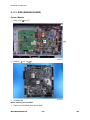
Electrical Components
MF Models
1.
Rear cover (
p.4-5)
2.
Controller box cover (
3.
FCU and Speaker bracket (
4.
EGB [A] (all
5.
EEPROM [B]
s,
p.4-54)
p.4-54)
x6)
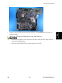
When installing the new EGB
1.
Remove the EEPROM from the old EGB.
M095/M096/M099/M100
4-60
SM
2.
Install it on the new EGB with the mark [A] pointing to the right side of the board after you
replace the EGB.
3.
Replace the EEPROM if the EEPROM on the old EGB is defective.
Keep the EEPROM away from any objects that can cause static electricity. Static
electricity can damage EEPROM data.
SM
Make sure that the EEPROM is correctly installed on the EGB.
4-61
M095/M096/M099/M100
Replacement
and
Adjustment
Electrical Components
Electrical Components
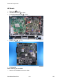
4.11.3 FCU (ONLY FOR MF MODELS)
1.
Rear cover (
p.4-5)
2.
Controller box cover (
3.
FCU and Speaker bracket (
4.
FCU [A] (
p.4-54)
p.4-54)
x 4)
M095/M096/M099/M100
4-62
SM
Electrical Components
4.11.4 INTERLOCK SWITCHES
1.
Operation panel (
p.4-6)
2.
Rear cover (
3.
Left cover (
4.
Interlock switch base [A] (
p.4-5)
Replacement
and
Adjustment
p.4-8)
5.
x 4,
x 4)
Removing the spring [B] first makes this procedure easier.
Remove all the connectors after the interlock switch base has been removed.
Two interlock switches [C] at the outside of the base and one interlock switch [D] at the
inside of the base (hooks x 2)
SM
4-63
M095/M096/M099/M100
Electrical Components
4.11.5 FUSING FAN MOTOR
1.
Operation panel (
2.
Rear cover (
3.
Left cover (
4.
Interlock switch base (
5.
Fusing fan base [A] (
6.
Fusing fan motor [B] (hooks x 2,
p.4-6)
p.4-5)
p.4-8)
p.4-63)
x 2,
x 1)
x 1)
Install the fusing fan motor with its decal facing the outside of the machine.
M095/M096/M099/M100
4-64
SM
Electrical Components
4.11.6 FUSING STRIPPER PAWL SOLENOID
Open the front cover.
2.
Open the top cover.
3.
Rear cover (
p.4-5)
4.
Right cover (
p.4-7)
5.
Fusing stripper pawl solenoid assembly [A] (
Replacement
and
Adjustment
1.
SM
4-65
x 4,
x 1)
M095/M096/M099/M100
Electrical Components
6.
Fusing stripper pawl solenoid [B] (
M095/M096/M099/M100
x 2)
4-66
SM
Electrical Components
4.11.7 FUSING PRESSURE RELEASE SENSOR
Fusing stripper pawl solenoid assembly (
2.
Fusing pressure release sensor [B] (
p.4-65)
Replacement
and
Adjustment
1.
SM
[A] x 1, hooks x 4)
4-67
M095/M096/M099/M100
Electrical Components
4.11.8 LSU FAN MOTOR
1.
Operation panel (
2.
Rear cover (
3.
Left cover (
4.
LSU fan motor [A] (hooks x 2,
p.4-6)
p.4-5)
p.4-8)
x 1)
Install the LSU fan motor with its decal facing the outside of the machine.
M095/M096/M099/M100
4-68
SM
Electrical Components
4.11.9 ID CHIP BOARD
1.
Operation panel (
p.4-6)
2.
Rear cover (
3.
Left cover (
4.
Controller box cover (printer model:
p.4-5)
p.4-8)
p.4-54) or FCU and Speaker bracket (MF model:
p.4-54)
5.
Disconnect the connector (CN305) on the EGB.
6.
Interlock switch base (
7.
Fusing fan base (
8.
Drive unit (
9.
Take the harnesses aside around the LSU fan base [A].
p.4-63)
p.4-64)
Replacement
and
Adjustment
p.4-19)
10. LSU fan base [A] (
x 2,
11. ID Chip Board [B] (
x 3)
SM
x 1)
4-69
M095/M096/M099/M100
Electrical Components
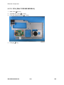
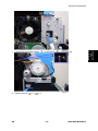
4.11.10 PSU
1.
Left cover (
p.4-8)
2.
Disconnect 2 connectors on the AIO motors, and remove all harnesses from the harness
guide [A].
3.
Harness guide [A] (
M095/M096/M099/M100
x 4,
x 2)
4-70
SM
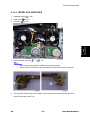
4.
Power cord bracket [B] (
5.
Ground cable [C] (
6.
Power switch assembly [D] (
SM
Replacement
and
Adjustment
Electrical Components
x 2)
x 1)
x 3,
x 2)
4-71
M095/M096/M099/M100
Electrical Components
7.
PSU assembly [E] (
8.
PSU [F] (
x 4,
x 7)
x 4)
M095/M096/M099/M100
4-72
SM
Electrical Components
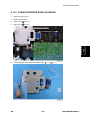
Fuse
There is a removable fuse on the PSU.
Fuse No.
Rating
FU101: NA, Taiwan
15 A, 125V
FU101: EU, ASIA
6.3A, 250V
Use a correct rating fuse for the fuse replacement. Never use a wrong rating fuse. If do
so, the machine may be damaged.
Never try direct connection of PSU circuit without a fuse.
Replacement
and
Adjustment
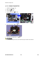
4.11.11 HIGH VOLTAGE POWER SUPPLY BOARD
1.
Remove all AIO cartridges.
2.
Operation panel (
3.
Rear cover (
p.4-5)
4.
Right cover (
p.4-7)
5.
High Voltage Power Supply Board [A] (
SM
p.4-6)
x 5, grounding cable x 1,
4-73
x 1)
M095/M096/M099/M100
Electrical Components
4.11.12 TEMPERATURE/HUMIDITY SENSOR
1.
Operation panel (
p.4-6)
2.
Rear cover (
p.4-5)
3.
Right cover (
p.4-7)
4.
Temperature/Humidity sensor [A] (
x 1,
x 1)
4.11.13 DUPLEX MOTOR
1.
Operation panel (
p.4-6)
2.
Left cover (
3.
Interlock switch base (
p.4-63)
4.
Fusing harness guide (
p.4-45)
5.
Fusing thermistor harness guide [A] (
6.
Duplex timing belt [B]
p.4-8)
M095/M096/M099/M100
x 2,
4-74
x 1)
SM
7.
Left bracket [D] (Printer models:
8.
Duplex motor [E] (
SM
x 2,
x 4, MF Models:
x 5 including [C])
x 1)
4-75
M095/M096/M099/M100
Replacement
and
Adjustment
Electrical Components
Electrical Components
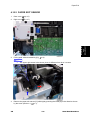
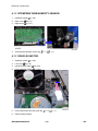
4.11.14 SPEAKER (ONLY FOR MF MODELS)
1.
Rear cover (
p.4-5)
2.
Controller box cover (
p.4-54)
3.
Speaker [A] (
x 1)
x 2,
M095/M096/M099/M100
4-76
SM
Electrical Components
4.11.15 EEPROM
Replacement and Reinstallation procedures for the EEPROM are included in the "EGB
(Engine Board)" replacement procedure. Refer to "EGB (Engine Board)" for details.
When replacing an old EEPROM with a new EEPROM, EEPROM setting is required. Follow the
EEPROM setting procedure described below.
Do the following steps 1 to 9 with the front cover of the machine open. After completing
these steps, turn off the machine.
1.
Open the front cover and turn on the machine.
The machine may issue an error code (because the cover is open), but continue
2.
Enter "Engine Maintenance" in the "Maintenance Mode Menu".
3.
Select "Init Engine EEPROM" item and execute it to initialize the EEPROM.
4.
Press the "Clear/Stop" key to exit the "Engine Maintenance" menu.
5.
Select the "Serial No." item, and then input a serial number.
Ask your supervisor about how to access the serial number input display.
6.
Exit the serial number input display, and then enter "Engine Maintenance" again.
7.
Select "Destination", and then select a destination.
8.
Select "Model", and then select a model.
9.
Select "PnP Name", and then select a plug and play name.
10. Select "LSU Adjustment", and then input the LSU (laser optics housing unit) setting values
if they are available.
11. Turn off the machine.
12. Turn on the machine with the front cover open.
13. Enter "Engine Maintenance" in the "Maintenance Mode Menu" again.
14. Close the front cover.
15. Select "Trans. Belt Adjust", and then execute "Trans. Belt Adjust" to adjust the ITB (Image
Transfer Belt) unit.
16. Select "Fuser SC Detect", and then select "ON" or "OFF" for the consecutive fusing jam
detection.
The default setting is "OFF". Select "ON" only if the customer wants to use this
feature.
17. Select "Registration", and then adjust the registration for each direction (vertical and
SM
4-77
M095/M096/M099/M100
Replacement
and
Adjustment
this procedure.
Electrical Components
horizontal direction) and tray if necessary.
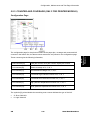
18. Select "2nd Transfer Fuser Temp", and then adjust the transfer roller bias and the
temperature reduction of the fusing unit for each paper type and for the front and back
sides. The default settings for normal operation are all '0'.
19. Perform “Color Registration” in the “Engine Maintenance” menu.
20. Turn the power off and on.
MUSIC will be performed automatically.
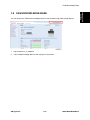
21. Print out the test chart (
p.4-11), and make sure that MUSIC was performed
successfully.
If MUSIC is not performed successfully, see “If MUSIC has not been performed
successfully” (
p.4-11).
22. If necessary, adjust the registration settings for the front and rear sides of each paper tray in
the “Engine Maintenance” menu.
23. Exit "Engine Maintenance".
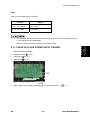
Checking that MUSIC was Performed Correctly
Four sets of vertical lines appear on the test chart (C and k, M and k, Y and k…). In each set,
look for vertical lines that are aligned within the region defined by “OK”.
If all sets have at least one set of vertical lines that are aligned [A], MUSIC was successful.
M095/M096/M099/M100
4-78
SM
ADF (only for MF Models)
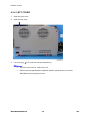
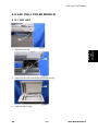
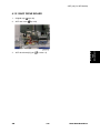
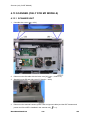
4.12 ADF (ONLY FOR MF MODELS)
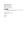
4.12.1 ADF UNIT
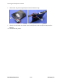
Stand left cover [A]
2.
Disconnect the ADF harness [B] and power cord [C].
3.
Open the ADF unit [D]
SM
Replacement
and
Adjustment
1.
4-79
M095/M096/M099/M100
ADF (only for MF Models)
4.
Release the three hooks of the right hinge [E]
5.
Lift the ADF unit.
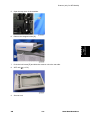
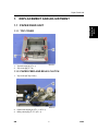
4.12.2 ORIGINAL TRAY
1.
Open the ADF cover.
2.
Release the front tab [A].
3.
Original tray [B]
M095/M096/M099/M100
4-80
SM
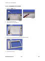
ADF (only for MF Models)
1.
Open the ADF cover.
2.
Release the lock lever [A]
3.
ADF feed unit [B]
Replacement
and
Adjustment
4.12.3 ADF FEED UNIT
4.12.4 ADF SEPARATION PAD
1.
Open the ADF cover.
2.
ADF feed unit (
3.
ADF separation pad [A] (hooks x 2, spring x 1)
SM
p.4-81)
4-81
M095/M096/M099/M100
ADF (only for MF Models)
4.12.5 ADF FRONT COVER
1.
ADF unit (
p.4-79)
2.
Original Tray (
3.
ADF feed unit (
4.
ADF front cover [A] (
p.4-80)
p.4-81)
x 1)
4.12.6 ADF REAR COVER
1.
ADF unit (
p.4-79)
2.
Original Tray (
3.
ADF feed unit (
4.
ADF rear cover [A] (
p.4-80)
p.4-81)
M095/M096/M099/M100
x 2)
4-82
SM
ADF (only for MF Models)
4.12.7 ADF COVER
ADF unit (
2.
ADF front cover (
p.4-82)
3.
ADF rear cover (
p.4-82)
4.
ADF top cover [A] (tabs x 2)
SM
p.4-79)
Replacement
and
Adjustment
1.
4-83
M095/M096/M099/M100
ADF (only for MF Models)
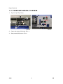
4.12.8 ADF MOTOR
1.
ADF unit (
p.4-79)
2.
Original Tray (
3.
ADF feed unit (
4.
ADF front cover (
p.4-82)
5.
ADF rear cover (
p.4-82)
6.
ADF drive unit [A] (
p.4-80)
p.4-81)
M095/M096/M099/M100
x 4, all
s)
4-84
SM
ADF (only for MF Models)
7.
ADF motor assembly [B] (
8.
ADF motor [C] (
x 2)
Replacement
and
Adjustment
x 2)
SM
4-85
M095/M096/M099/M100
ADF (only for MF Models)
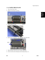
4.12.9 ORIGINAL SET SENSOR
1.
ADF unit (
p.4-79)
2.
ADF feed unit (
3.
ADF motor assembly (
p.4-84)
4.
Feed roller holder [A] (
x 1)
5.
Upper guide [B] (
6.
Original set sensor [C] (hooks x 3)
p.4-81)
M095/M096/M099/M100
x 2)
4-86
SM
ADF (only for MF Models)
4.12.10 ADF COVER OPEN SENSOR
1.
Original tray (
2.
ADF rear cover (
3.
ADF cover open sensor (
SM
p.4-80)
x 1,
Replacement
and
Adjustment
p.4-82)
x 1)
4-87
M095/M096/M099/M100
ADF (only for MF Models)
4.12.11 ADF FEED SENSOR
1.
ADF unit (
p.4-79)
2.
ADF feed unit (
3.
Sensor cover [A] (
4.
ADF feed sensor [B] (hooks x 2)
p.4-81)
M095/M096/M099/M100
x 2)
4-88
SM
ADF (only for MF Models)
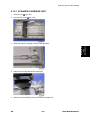
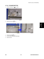
4.12.12 ADF DRIVE BOARD
1.
Original tray (
2.
ADF rear cover (
3.
ADF drive board [A] (all
SM
p.4-80)
Replacement
and
Adjustment
p.4-82)
s, hooks x 2)
4-89
M095/M096/M099/M100
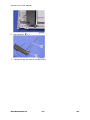
Scanner (only for MF Models)
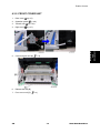
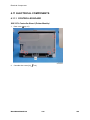
4.13 SCANNER (ONLY FOR MF MODELS)
4.13.1 SCANNER UNIT
1.
Controller box cover (
p.4-54)
2.
Disconnect the flat cable with the ferrite core [A] (
3.
Stand left cover [B] and right cover [C] (hook x 1 each)
4.
Disconnect the scanner harness, power cord and ground cable (and the ADF harness and
x 1, hooks x 2).
power cord if the ADF is installed in the scanner unit) (
M095/M096/M099/M100
4-90
x 1).
SM
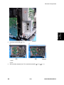
Scanner (only for MF Models)
Open the top cover of the machine.
6.
Remove the stepped screw [D].
7.
Push the lock button [E] and slide the scanner unit to the rear side.
8.
ADF unit (
9.
Scanner unit
Replacement
and
Adjustment
5.
SM
p.4-79)
4-91
M095/M096/M099/M100
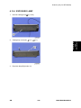
Scanner (only for MF Models)
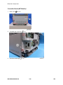
4.13.2 SCANNER TOP COVER
1.
Scanner unit (
p.4-90)
2.
Turn over the scanner unit.
3.
Scanner front cover [A] (tabs x 3)
4.
Remove the six screws at the bottom of the scanner base [B].
5.
Scanner top cover [C]
M095/M096/M099/M100
4-92
SM
Scanner (only for MF Models)
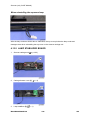
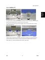
4.13.3 SCANNER CARRIAGE UNIT
1.
Scanner unit (
p.4-90)
2.
Scanner top cover (
3.
Slide the scanner carriage unit [A] to the right side.
4.
Remove the timing belt tension spring [B]
5.
Remove the flat cable [C] from the scanner carriage unit.
Replacement
and
Adjustment
p.4-92)
SM
4-93
M095/M096/M099/M100
Scanner (only for MF Models)
6.
Bar holder [D] (
7.
Carriage bar [E] and scanner carriage unit [F]
x 1)
M095/M096/M099/M100
4-94
SM
Scanner (only for MF Models)
4.13.4 EXPOSURE LAMP
Scanner carriage unit (
p.4-93)
2.
Carriage top cover [A] (
x 2,
3.
Exposure lamp [B] (hooks x 2)
x 1)
Replacement
and
Adjustment
1.
SM
4-95
M095/M096/M099/M100
Scanner (only for MF Models)
When reinstalling the exposure lamp
Wire the lamp cords as shown above. Otherwise, the top cover pinches the lamp cords and
damages them when reinstalling the top cover on the scanner carriage unit.
4.13.5 LAMP STABILIZER BOARD
1.
Scanner carriage unit (
2.
Carriage bottom cover [A] (
3.
Lamp stabilizer [B] (
M095/M096/M099/M100
p.4-93)
x 2)
x 1)
4-96
SM
Scanner (only for MF Models)
4.13.6 SCANNER MOTOR
1.
Scanner carriage unit (
p.4-93)
2.
Scanner motor [A] (
3.
Carriage rail [B] (
4.
Ground plate [C] (double-sided tape)
5.
Scanner motor
Replacement
and
Adjustment
x 3)
SM
x 2)
4-97
M095/M096/M099/M100
SYSTEM MAINTENANCE REFERENCE
R E V I S I O N H I S T O RY
P a ge
Date
A d de d /U pd at e d /N ew
None
Image Problems
5. SYSTEM MAINTENANCE REFERENCE
5.1 IMAGE PROBLEMS
5.1.1 OVERVIEW
Image problems may appear at regular intervals that depend on the circumference of certain
components. The following diagram shows the possible symptoms (black or white dots at
Abnormal image at 23.5 mm intervals: Paper feed roller.
Abnormal image at 59 mm intervals: Paper transfer roller
Abnormal image at 25 mm intervals: Image transfer belt unit (Transfer roller)
Abnormal image at 30 mm intervals: Charge roller.
Abnormal image at 38 mm intervals: Registration roller
Colored spots at 27 mm intervals: AIO cartridge (Development roller)
Abnormal image at 61 mm intervals: Image transfer belt unit (Drive roller)
Colored spots at 76 mm intervals: AIO cartridge (OPC drum)
Abnormal image at 95 mm intervals: Fusing unit (Pressure roller)
Abnormal image at 76 mm intervals: Fusing unit (Heat roller)
5.1.2 IMAGE PROBLEM
Print out a “maintenance page” (all K, C, M, or Y), which will clarify if the cause is a problem with
one of the AIOs, Image transfer belt, image transfer roller, or the fusing unit (
p.5-37).
Occurs with 1-3 colors: AIO unit(s) failure
Occurs with all four colors: Image transfer belt, transfer roller or fusing unit failure
SM
5-1
M095/M096/M099/M100
System
Maintenance
Reference
regular intervals).
Error Codes
5.2 ERROR CODES
5.2.1 OVERVIEW
The error codes will be displayed on the LCD if the machine has a problem. These can be
recovered by a customer.
5.2.2 ERROR CODES LIST
Cover Open
000
The front or top cover is open.
1.
Close the front or top cover.
2.
Replace the interlock switches or actuator mechanism.
010
AIO Set Error (Black)
011
AIO Set Error (Magenta)
012
AIO Set Error (Cyan)
013
AIO Set Error (Yellow)
Black AIO not set
Defective connection of the ID chip terminal on the black AIO
1.
Install the AIO (black, magenta, cyan or yellow).
2.
Reinstall or replace the AIO (black, magenta, cyan or yellow).
Waste Toner Bottle Set Error
014
Waste toner bottle not set
Disconnected or defective harness of the waste toner bottle set sensor
Defective waste toner bottle set sensor
1.
Install the waste toner bottle.
2.
Check or replace the harness of the waste toner bottle set sensor.
3.
Replace the waste toner bottle set sensor.
M095/M096/M099/M100
5-2
SM
Error Codes
Tray/Paper Selection Error
030
No paper in the tray or tray not set in the machine
Paper size requested by the job does not match the paper in the tray
1.
Install the tray or put the correct size paper in the tray.
2.
Check the paper setting in the user menu mode.
Paper Selection Error: Feed and Exit
031
Paper size requested by the job does not match the paper in the tray
Selection error for the paper feed and paper exit location in duplex mode
Check the paper feed and exit location in the user menu mode.
Jam Error: No Feed from Tray 1
050
Paper slipped
System
Maintenance
Reference
Remove the paper jam at tray 1.
Jam Error: No Feed from Optional Tray
052
Paper slipped
Remove the paper jam at the optional tray (Tray 2).
Inner Jam Error: Registration/ Paper Exit
A sheet of paper stays at the registration sensor or paper exit sensor.
055
Paper slipped
Paper double feed
Remove the paper jam at the registration sensor or paper exit sensor.
SM
5-3
M095/M096/M099/M100
Error Codes
Paper Exit Jam Error: Paper Exit/ Fusing Unit
A sheet of paper stays at the paper exit sensor or winds around the rollers in the
056
fusing unit.
Paper slipped
A sheet of paper is wound around the rollers in the fusing unit
Remove the paper jam at the paper exit sensor or in the fusing unit.
Printing Error: No Paper
070
No paper in the tray
Put paper in the tray.
080
081
Toner Near End: Black AIO
Toner End: Black AIO
Black toner near-end or end
Replace the black AIO.
082
083
Toner Near End: Magenta AIO
Toner End: Magenta AIO
Magenta toner near-end or end
Replace the magenta AIO.
084
085
Toner Near End: Cyan AIO
Toner End: Cyan AIO
Cyan toner near-end or end
Replace the Cyan AIO.
M095/M096/M099/M100
5-4
SM
Error Codes
086
087
Toner Near End: Yellow AIO
Toner End: Yellow AIO
Yellow toner near-end or end
Replace the yellow AIO.
088
089
Waste Toner Bottle: Near Full
Waste Toner Bottle: Full
Waste toner bottle near-full or full
Replace the waste toner bottle.
Color Registration (MUSIC) Error
Color registration (MUSIC) failure
This error is not displayed even if this error occurs. It is just logged. This error is
automatically recovered after the color registration (MUSIC) has been done
successfully.
SM
5-5
M095/M096/M099/M100
System
Maintenance
Reference
999
Service Call Conditions
5.3 SERVICE CALL CONDITIONS
5.3.1 SUMMARY
This machine issues an SC (Service Call) code if an error occurs on the machine. The error
code can be seen on the operation panel.
Make sure that you understand the following points;
1.
All SCs are logged.
2.
At first, always turn the main switch off and on if an SC code is issued.
3.
First, disconnect then reconnect the connectors before you replace the PCBs, if the
problem concerns electrical circuit boards.
4.
First, check the mechanical load before you replace motors or sensors, if the problem
concerns a motor lock.
5.
Fusing related SCs: To prevent damage to the machine, the main machine cannot be
operated until the fusing related SC has been reset by a service representative.
Enter the engine maintenance mode.
Press "O.K" in "Fuser SC Reset" with engine maintenance mode, and then turn the
main power switch off and on.
M095/M096/M099/M100
5-6
SM
Service Call Conditions
5.3.2 ENGINE SC
SC 1xx (Other Error)
Serial Number Error
The serial number stored in the memory (EGB) is not correct.
EEPROM defective
EGB replaced without original EEPROM
1.
Check the serial number.
2.
If the stored serial number is incorrect, contact your supervisor.
System
Maintenance
Reference
195
SM
5-7
M095/M096/M099/M100
Service Call Conditions
SC 2xx (Laser Optics Error)
Polygon motor error 1: ON timeout
202
The polygon mirror motor does not reach the targeted operating speed within 5
sec. after turning on or changing speed.
Polygon motor error 2: OFF timeout
203
The polygon mirror motor does not leave the READY status within 3 sec. after the
polygon motor switched off.
Polygon motor error 3: XSCRDY signal error
The SCRDY_N signal remains HIGH for 200 ms while the LD unit is firing.
204
Polygon motor/driver board harness loose or disconnected
Polygon motor/driver board defective
Laser optics unit defective
IPU (EGB) defective
1.
Replace the interface harness of the laser optics unit.
2.
Replace the laser optics unit.
3.
Replace the EGB (Engine Board).
M095/M096/M099/M100
5-8
SM
Service Call Conditions
Laser Synchronizing Detection Error: [K]/[Y]
220
The laser synchronizing detection signal for LDB [K]/[Y] is not output after the LDB
unit has turned on while the polygon motor is rotating normally.
Laser Synchronizing Detection Error: [M]/[C]
The laser synchronizing detection signal for LDB [M]/[C] is not output after the
LDB unit has turned on while the polygon motor is rotating normally.
connection
Defective laser synchronizing detector
Defective LDB
Defective EGB
1.
Check the connectors.
2.
Replace the laser optics unit.
3.
Replace the EGB.
System
Maintenance
Reference
222
Disconnected cable from the laser synchronizing detection unit or defective
LD error
The IPU (EGB) detects a problem at the LD unit.
240
SM
Worn-out LD
Disconnected or broken harness of the LD.
1.
Replace the laser optics unit.
5-9
M095/M096/M099/M100
Service Call Conditions
SC 3xx (Charge Error)
High voltage power output error
The measured voltage is not correct when the EGB measures each charge output
(charge, development, image transfer belt unit, and transfer unit).
300
Disconnected or defective high voltage harness
Defective high voltage power supply
Defective EGB
1.
Check or replace the harnesses.
2.
Replace the high voltage power supply board
3.
Replace the EGB.
Black drum motor error
The LOCK signal error is detected when the EGB monitors the black drum motor
state. (This monitoring is done immediately after power-on, when the motor starts
396
rotating, and immediately after the motor stops.)
Disconnected or defective motor harness.
Motor slips due to excessive load
1.
Check the harness from the black drum motor. Replace it if necessary.
Color drum motor error
The LOCK signal error is detected when the EGB monitors the color drum motor
state. (This monitoring is done immediately after power-on, when the motor starts
397
rotating, and immediately after the motor stops.)
Disconnected or defective motor harness.
Motor slips due to excessive load
1.
Check the harness from the color drum motor. Replace it if necessary.
M095/M096/M099/M100
5-10
SM
Service Call Conditions
SC 4xx (Image Transfer and Transfer Error)
TM sensor error
The CPU detected a low voltage of the positive reflection output under the
threshold in the TM sensor.
400
TM sensors are dirty.
A solid print out due to an electrostatic charging error
The TM sensor is defective.
1.
Clean the TM sensors.
2.
Replace the TM sensors.
3.
Check the image transfer unit.
4.
Turn the power Off and On.
ITB (Image Transfer Belt) Unit: Home Position Error
The ITB contact sensor does not detect the home position of the ITB for 5
ITB (Image Transfer Belt) Unit: Contact Position Error
The ITB contact sensor does not detect the contact position of the ITB for 5
seconds after the ITB unit has moved to the contact position.
445
ITB (Image Transfer Belt) Unit: No-contact Position Error
The ITB contact sensor does not detect the home position of the ITB for 5
seconds after the ITB unit has moved to no-contact position.
SM
Defective ITB contact motor
Defective ITB contact sensor
Defective ITB unit
1.
Replace the ITB contact motor.
2.
Replace the ITB contact sensor.
3.
Replace the ITB unit.
5-11
M095/M096/M099/M100
System
Maintenance
Reference
seconds after the ITB unit initialization has been done.
Service Call Conditions
Agitator Motor Error
The agitator motor error is detected twice for 10 msec during the initialization at
power-on or after the cover is closed.
480
Disconnected or defective harness
Defective agitator motor
1.
Check or replace the harness.
2.
Replace the agitator motor.
ITB (Image Transfer Belt) Unit Set Error
The TM sensor does not detect the reflection from the ITB.
490
No ITB unit in the machine
Dirty TM sensor
1.
Check the installation of the ITB unit.
2.
Clean the TM sensor.
M095/M096/M099/M100
5-12
SM
Service Call Conditions
SC 5xx (Motor and Fusing Error)
Transport/Fusing Motor Error
The LOCK signal error is detected when the EGB monitors the transport/fusing
motor state. (This monitoring is done immediately after power-on, when the motor
500
starts rotating, and immediately after the motor stops.)
Disconnected or defective motor harness.
Motor slips due to excessive load
1.
Check the harness from the transport/fusing motor. Replace it if
necessary.
LSU Fan Motor Error
A LOCK signal is not detected for more than ten seconds while the motor START
530
Disconnected or defective motor harness.
Defective LSU fan motor
1.
Check or replace the motor harness.
2.
Replace the LSU fan motor.
System
Maintenance
Reference
signal is on and if this error occurs twice consecutively, this SC is issued.
Fusing Fan Motor Error
A LOCK signal is not detected for more than ten seconds while the motor START
signal is on and if this error occurs twice consecutively, this SC is issued.
531
SM
Disconnected or defective motor harness.
Defective LSU fan motor
1.
Check or replace the motor harness.
2.
Replace the fusing fan motor.
5-13
M095/M096/M099/M100
Service Call Conditions
Thermistor Error
The thermistor output is less than 0°C for 7 seconds.
Disconnected thermistor
Defective harness connection
541
1.
Check the harness connection of the thermistor.
2.
Replace the fusing unit.
Execute "Engine Maintenance Menu" to recover the machine after
completing the recovery procedure. Otherwise, the machine continues to
issue this SC code and cannot be operated.
Print Ready Temperature Error
The heating roller temperature increase during a set time is not correct.
The fusing temperature does not reach the print ready temperature within a
set time after the fusing lamp has turned on.
542
Defective thermistor
Incorrect power supply input at the main power socket
Defective fusing lamp
1.
Check the voltage of the wall outlet.
2.
Replace the fusing unit
3.
Replace the fusing lamp.
Execute "Engine Maintenance Menu" to recover the machine after
completing the recovery procedure. Otherwise, the machine continues to
issue this SC code and cannot be operated.
M095/M096/M099/M100
5-14
SM
Service Call Conditions
High Temperature Detection Error
This SC is issued if one of following conditions occurs:
The thermistor (center) detects 255°C or thermistor (end) detects 245°C.
The thermistor (center) detects a 3°C increment or more for five seconds at
220°C or more or the thermistor (end) detects a 4°C increment or more for
five seconds at 210°C or more.
543
Defective I/O control (EGB)
Defective EGB
1.
Replace the EGB
Execute "Engine Maintenance Menu" to recover the machine after
completing the recovery procedure. Otherwise, the machine continues to
issue this SC code and cannot be operated.
The fusing lamp is fully-powered for a certain time while the fusing unit stays in the
stand-by mode and is not rotating.
545
Deformed thermistor
Thermistor not in the correct position
Defective fusing lamp
1.
Replace the fusing unit.
2.
Replace the fusing lamp.
Execute "Engine Maintenance Menu" to recover the machine after
completing the recovery procedure. Otherwise, the machine continues to
issue this SC code and cannot be operated.
SM
5-15
M095/M096/M099/M100
System
Maintenance
Reference
Heating Lamp Full-Power Error
Service Call Conditions
Zero Cross Error
The zero cross signal is not detected for three seconds even though the fusing
lamp relay is on after turning on the main power or closing the front door.
547
Defective fusing lamp relay
1.
Turn the main power switch off and on.
Execute "Engine Maintenance Menu" to recover the machine after
completing the recovery procedure. Otherwise, the machine continues to
issue this SC code and cannot be operated. The power should be turned
off and on after the recovery procedure.
Low Temperature Error
The center thermistor detects 100°C or less for 4 seconds.
548
Defective fusing lamp
Defective thermistor
1.
Replace the fusing unit.
2.
Replace the fusing lamp.
Execute "Engine Maintenance Menu" to recover the machine after
completing the recovery procedure. Otherwise, the machine continues to
issue this SC code and cannot be operated.
M095/M096/M099/M100
5-16
SM
Service Call Conditions
Zero Cross Frequency Error
The detection error occurs ten times consecutively in ten zero cross signal
detections. This error is defined when the detected zero cross signal is 17 or
less/27 or more for 0.2 seconds.
Defective fusing lamp relay
Unstable input power source
557
1.
Check the power supply source.
2.
Replace the fusing unit.
3.
Turn the main power switch off and on.
Execute "Engine Maintenance Menu" to recover the machine after
completing the recovery procedure. Otherwise, the machine continues to
issue this SC code and cannot be operated. The power should be turned
Consecutive Fusing Jam
The paper jam counter for the fusing unit reaches 3. The paper jam counter is
cleared if the paper is fed correctly.
This SC is activated only when this function is enabled with "Engine Maintenance"
(default "OFF").
559
Defective fusing unit
Defective fusing control
1.
Clear this SC to send a command after a jam removal.
2.
Turn off this function after a jam removal.
Execute "Engine Maintenance Menu" to recover the machine after
completing the recovery procedure. Otherwise, the machine continues to
issue this SC code and cannot be operated.
SM
5-17
M095/M096/M099/M100
System
Maintenance
Reference
off and on after the recovery procedure.
Service Call Conditions
SC 6xx (Communication and Other Error)
EEPROM Error
An unexpected value exists in the initialization flag of the EEPROM
669
EEPROM not initialized
Defective EEPROM
1.
Initialize the EEPROM.
2.
Replace the EEPROM.
3.
Replace the EGB.
GAVD Communication Error
The ID of the GAVD is not identified during initialization.
690
The chip ID of the GAVD cannot be detected by the machine at power-on.
Defective EGB
1.
Replace the EGB.
M095/M096/M099/M100
5-18
SM
Service Call Conditions
5.3.3 CONTROLLER SC
SC8xx
Service Cycle Power
819
Incorrect combination of EGB and controller board.
An unexpected error occurs in the EEPROM on the controller board.
Controller board defective
1.
Install the correct EGB and controller boards for this machine.
2.
Replace the controller board
USB/ Network Device Error
An interface error in the USB connection or NIB connection occurs.
Controller board detective
1.
Replace the controller board.
System
Maintenance
Reference
823
EEPROM Error
824
An EEPROM check error at power-on occurs.
Controller board detective
1.
SM
Replace the controller board.
5-19
M095/M096/M099/M100
Service Call Conditions
On-Board Memory Check Error
827
An on-board memory check error at power-on occurs.
Controller board detective
1.
Replace the controller board.
ROM Checksum Error
828 A ROM checksum error at power-on occurs.
1.
Replace the controller board.
M095/M096/M099/M100
5-20
SM
Service Menu
5.4 SERVICE MENU
5.4.1 OVERVIEW
These models have several service menus. Each service menu has several adjustment items.
This section explains how to enter each service menu and what you can do in each service
menu.
Each menu is classified into two "Modes" depending on how you enter the service menus.
"Menu Mode" can be executed by pushing a sequence of keys.
"Special Mode" can be executed if you press certain keys at the same time as you turn the
power on.
This service manual is a combined manual for the MF Model and the Printer Model.
Therefore, the order of some service menus is different from the actual one in the
Printer model.
Menu Mode
Maintenance Mode Menu
This is a menu for maintenance and service.
Special Mode
This is a menu for initializing all information stored
in the controller, except for some counters.
These counters are initialized:
Print/Scan/Copy/Fax functional Counter, Jam
Counter
Factory Default Settings Menu
These counters are not initialized:
Printer/Scanner Engine Counter, which are
printed in the "Configuration Page".
After initializing with this menu, when the user
powers on the machine, the Initial Setup Menu
appears. The user must select Language in
Country in this menu.
Fax Service Test Menu (only for MF
models)
SM
This is a menu for checking the fax mode.
5-21
M095/M096/M099/M100
System
Maintenance
Reference
Each menu is classified as follows:
Service Menu
5.4.2 MAINTENANCE MODE MENU
Menu List
Display Info
Displays the Model Name, Depends on Engine
Model Name
Firmware Settings
CTL FW Version
FAX FW Version
FW Version
Engine FW
Version
PDL FW Version
Displays the Firmware Version
Displays the Facsimile Firmware Version.
(M099 doesn't support this)
Displays the Engine Firmware Version
Displays the PDL Firmware Version.
(only for M096/M100)
Displays the following counters of the printer
Printer Counter
engine.
Total Page/ Color Image/ Black Image
Displays the sum total of scanner counters for
Scanner Counter
each mode.
Total Page/ Black Page/ Color Page
/ ADF Used
Counter
Displays the number of paper jams at each
Jam Counter
location.
Total/ ADF/ Printer Output Bin/ Internal/ Tray1
/ Tray2
Displays the number of paper misfeeds with tray 1
Coverage
or tray 2.
Coverage1 (Tray 1)/ Coverage2 (Tray2)
M095/M096/M099/M100
5-22
SM
Service Menu
Print Reports
G3 protocol dump of the latest communication is
G3 Protocol dump list
printed. (M099 doesn't support this)
Off (Default)/ Error/ On
Engine Maintenance
Determines the maximum amount of ink/toner you
can use in any area of your text. This is where you
Text
are controlling exactly how much ink will be used
during printing.
[200 to 400 / 250 (Default)/ 10/step]
Setting 0: Off
Determines the maximum amount of ink/toner you
Toner Limit
Graphic
you are controlling exactly how much ink will be
used during printing.
[200 to 400 / 250 (Default)/ 10/step]
Setting 0: Off
Determines the maximum amount of ink/toner you
can use in any area of your image. This is where
Image
you are controlling exactly how much ink will be
used during printing.
[200 to 400 / 250 (Default)/ 10/step]
Setting 0: Off
NA Model: RICOH/ 'nul'
PNP Name
EU Model: RICOH/ NRG/ LANIER
ASIA Model: RICOH/ LANIER
China Model: RICOH
SM
5-23
M095/M096/M099/M100
System
Maintenance
Reference
can use in any area of your graphic. This is where
Service Menu
Destination
Sets the destination and updates the engine setting.
DOM/ NA (Default)/ EU/ CHIN/ TAIWAN/ ASIA
Sets the Media type.
Thin Paper / Thick Paper / Plain Paper1 / Plain
Media Type
Paper2 / Recycled / Color / Letterhead / Preprinted
/ Prepunched / Label Paper / Bond Paper /
Cardstock / Envelope / Thick Post / Thinner Paper
2nd Transfer
2nd Transfer
Front
Fuser Temp.
2nd Transfer
Back
Fuser
Temperature
Adjusts the transfer roller current, based on the
default value.
[-15 to 15 / 0 (Default) / 1 A/step]
Adjusts the transfer roller current, based on the
default value.
[-15 to 15 / 0 (Default) / 1 A/step]
Adjusts the temperature of the fusing unit, based
on the default value.
[-30 to 0 / 0 (Default) / 2°C/step]
Adjusts the horizontal registration for tray 1. If the
Horiz. Tray1
machine settings are reset to the factory defaults,
this value does not change.
[-15 to 15 / 0 (Default) / 1 mm/step]
Adjusts the vertical registration for tray 1. If the
Vert.Tray1
machine settings are reset to the factory defaults,
this value does not change.
[-15 to 15 / 0 (Default) / 1 mm/step]
Registration
Adjusts the horizontal registration for tray 2. If the
Horiz.Tray2
machine settings are reset to the factory defaults,
this value does not change.
[-15 to 15 / 0 (Default) / 1 mm/step]
Adjusts the vertical registration for tray 2. If the
Vert.Tray2
machine settings are reset to the factory defaults,
this value does not change.
[-15 to 15 / 0 (Default) / 1 mm/step]
M095/M096/M099/M100
5-24
SM
Service Menu
Adjusts the horizontal registration for the bypass
Horiz Bypass
tray. If the machine settings are reset to the factory
Tray
defaults, this value does not change.
[-15 to 15 / 0 (Default) / 1 mm/step]
Adjusts the vertical registration for the bypass tray.
Vert Bypass
If the machine settings are reset to the factory
Tray
defaults, this value does not change.
[-15 to 15 / 0 (Default) / 1 mm/step]
Adjusts the horizontal registration for the back side
Horiz.Dup Back
in duplex mode. If the machine settings are reset
to the factory defaults, this value does not change.
[-15 to 15 / 0 (Default) / 1 mm/step]
Adjusts the vertical registration for the back side in
Vert.Dup Back
duplex mode. If the machine settings are reset to
the factory defaults, this value does not change.
This clears all counters except "Full Color" and "Black and White" in
Init Engine
EEPROM
the total counter.
When you execute "Init Engine EEPROM", the engine EEPROM is
initialized.
Turn the machine power off/on after you change this setting.
Displays only
PE-P2a / MF3a
Model
PE-P2c / MF3c
Displays the current model in a dropdown list.
Do not change this setting (Designed for Factory Use).
00* – 7F
Brand ID
Displays the current brand ID number.
Do not change this setting (Designed for Factory Use).
00* – 7F
Maintenance ID
Displays the current maintenance ID number.
Do not change this setting (Designed for Factory Use).
SM
5-25
M095/M096/M099/M100
System
Maintenance
Reference
[-15 to 15 / 0 (Default) / 1 mm/step]
Service Menu
LSU Adjustment
Input 160 bytes
setting.
Character: alphanumeric "0-9", "a-f", "A-F", only
valid data can be input.
Input length: 160 bytes
When you execute "Trans. Belt Adjust", the transfer belt adjustment is
Trans. Belt Adjust done. This calibrates the motor speed to match the length of the new
transfer belt.
If On, the engine detects SC559. If Off, the engine
Fuser SC Detect
On/Off*
Color
The engine will do color registration and density tuning automatically.
Registration
The printer will warm up automatically after this setting is changed.
Reset Transfer
Unit
does not detect "Fusing SC Reset".
Resets the transfer unit life counter.
Reset Fuser Unit
Resets the fusing unit life counter.
Fuser SC Reset
Resets the Fusing related SC.
Reset 2nd
Transfer unit
Special Mode
Resets the 2nd transfer unit (transfer roller) life counter.
DFU
Reset Count
(only for Printer
Resets counters to factory defaults.
Models)
Clear log
(only for Printer
Clears the error and the jam counter logs.
Models)
M095/M096/M099/M100
5-26
SM
Service Menu
Sets the tentative density of each mode.
Tentative
Text: 100 / 50 / 30 (Default: 100)
Density
Image: 100 / 50 / 30 (Default: 50)
Graphic:100 / 50 / 30 (Default: 30)
Economy Color
Sets the conversion mode for the economy color
Print
print.
Conversion
Mode
No: No conversion is executed.
Color Up Mode: Converts into economy color. The
image density is decreased.
B&W Up Mode: Converts into Economy Black and
white.
Sets whether to display the PM parts replacement notice and whether
to stop the engine.
At near end: No Notice / Not Stopped
0
PM Parts Rep
At near end: No Notice / Not Stopped
1
Notice
At life end: No Notice / Not Stopped
At near end: Notice / Not Stopped
2 (default)
At life end: Notice “Replace Now” / Not Stopped
At near end: Notice “Replace Soon” / Not Stopped
3
At life end: Notice “Replace Now” / Stopped
SM
5-27
M095/M096/M099/M100
System
Maintenance
Reference
At life end: Notice “Replace Now” / Not Stopped
Service Menu
Scan Maintenance (only for MF models)
Mono
Compression
Setting
Sets the monochrome compression type for scanning.
MH (Default)/ MR/ MMR
ADF Main Reg.
ADF Sub Reg.
Registration
Adjust
Adjusts the ADF Scan main-scan registration.
[-2.0 to 2.0 / 0 (Default)/ 0.1 %/step]
Adjusts the ADF Scan sub-scan registration.
[-2.0 to 2.0 / 0 (Default)/ 0.1 %/step]
Flatbed Main
Adjusts the Flatbed Scan main-scan registration.
Reg.
[-2.0 to 2.0 / 0 (Default)/ 0.1 %/step]
Flatbed Sub
Adjusts the Flatbed Scan sub-scan registration.
Reg.
[-2.0 to 2.0 / 0 (Default)/ 0.1 %/step]
ADF Main Reg.
ADF Sub Reg.
Adjusts the ADF Scan main-scan magnification.
[-0.9 to 0.9 / 0 (Default)/ 0.1 %/step]
Adjusts the ADF Scan sub-scan magnification.
[-0.9 to 0.9 / 0 (Default)/ 0.1 %/step]
Size Adjust
Flatbed Main
Adjusts the Flatbed Scan main-scan magnification.
Reg.
[-0.9 to 0.9 / 0 (Default)/ 0.1 %/step]
Flatbed Sub
Adjusts the Flatbed Scan sub-scan magnification.
Reg.
[-0.9 to 0.9 / 0 (Default)/ 0.1 %/step]
M095/M096/M099/M100
5-28
SM
Service Menu
Fax Maintenance (only for MF models)
Sets the reception level.
RX Level
[-43 dBm (Default)/ -33 dBm/ -26 dBm
/ -16 dBm]
Sets the transmission level.
[0 dBm/ -1 dBm/ -2 dBm/ -3 dBm/ -4 dBm
Modem Settings
TX Level
/ -5 dBm/ -6 dBm/ -7 dBm/ -8 dBm/ -9 dBm
/ -10 dBm/ -11 dBm/ -12 dBm/ -13 dBm
/ -14 dBm/ -15 dBm]
These selectors are used to improve the
Cable Equalizer
pass-band characteristics of analogue signals on
the telephone line.
[0Km (Default)/ 1.8Km/ 3.6Km/ 7.2Km]
This sets the number of training retries to be
repeated before automatic fallback.
[1 Time/ 2 Times (Default)/ 3 Times/ 4 Times]
Definition
Encoding
Sets the compression method for Tx/Rx.
[MMR+MR+MH (Default)/ MR+MH/ MH]
Timeout for response from the called station in
T0 Timer
T1 Timer
T4 Timer
SM
[35 Sec/ 45 Sec/ 55 Sec (Default)/ 60 Sec/ 90 Sec/
140 Sec]
Protocol
Definition Timer
automatic sending mode
Set the time length for the T1 timer.
[40 Sec (Default)/ 50 Sec]
Set the time length for the T4 timer.
[3 Sec (Default/ 4.5 Sec]
5-29
M095/M096/M099/M100
System
Maintenance
Reference
Training Retries
Protocol
Service Menu
Silence (No tone) detection time (Rx mode : FAX/
TAD Only)
Silence
After the line is connected via the external
Detection Time
telephone, the machine can detect silence (no
tone) for the time length specified by this setting.
[30 sec (Default)]
CNG tone detection time ( RX mode : FAX / TEL,
FAX / TAD Only)
CNG Tone
After the line is connected via the external
Detection Time
telephone, the machine can detect a CNG signal
for the time length specified by this setting.
[5 Sec (Default)/ 10 Sec]
Number of CNG cycles to be detected
RX Settings
CNG Cycles
This setting is only effective for FAX/TAD mode.
[1.5 Cycle (Default)/ 2.0 Cycle]
Determines the period when tones from the line
Tone Sound
are monitored.
Monitoring
[No Monitoring/ Up To Phase B (Default)/ All TX
Phases]
Pressing the Stop/Clear key can stop the current
Stop/Clear key
receiving operation. Received data is lost.
[Not Functional (Default)/ Functional]
Off-Hook Level
Off-Hook
Detection Period
M095/M096/M099/M100
Sets the off-hook detection threshold.
[10V (Default)/ 15V/ 20V/ 25V]
Sets the Off-Hook detection period.
200 ms (default)
800 ms
5-30
SM
Service Menu
Redial Interval
Sets the redial interval when Tx fails.
[5 Min/ 6 Min]
TX Settings
Redialings
Sets the number of redials when Tx fails.
[2 times/ 3 Times/ 4 Times/ 5 Times]
This sets the machine to ignore a DIS signal sent
Overseas
from the called station once in a sending
Comm Mode
operation.
[Off (Default)/ Ignore DIS Once]
Overseas Comm
If this setting is set to "On", the machine detects
Mode Settings
Minimum Time
Length
the CNG signal after the line is connected. If it is
set to "Off", the machine detects the CNG signal
as long as the line is connected.
[100 Ms/ 200 Ms/ 300 Ms/ 400 Ms (Default)]
This sets the number of pulses that are generated
Dial Pulse Setting Dial Pulse Type
N: Dialing '0' generates 10 pulses --- Dialing
'9' generates 9 pulses.
N+1: Dialing '0' generates 1 pulses --- Dialing
'9' generates 10 pulses.
10-N: Dialing '0' generates 10 pulses --Dialing '9' generates 1 pulse.
Tone Signal
Transmission
Time Length
Sets the tone signal transmission time length
[100 ms (Default)]
Minimum Pause
Sets the minimum pause during tone dialing
in Tone Dialing
[100 ms (Default)/ 150 ms/ 200 ms]
Tone Signal
Settings
Attenuator For
Pseudo
RingBack tone
To the Line
DTMF Level
SM
Sets the attenuator for pseudo ringback tone to
the line
[0 to 15 / 10 (Default)/ 1 dB/step]
Sets the transmission level of DTMF tones.
[-12 dBu / -11 dBu/ -10 dBu/ -8 dBu/ -6 dBu]
5-31
M095/M096/M099/M100
System
Maintenance
Reference
during dialing.
Service Menu
Sets the level difference between high band
DTMF Delta
frequency signals and low band frequency signals
when sending DTMF tones.
[2 dBu/ 3 dBu]
The machine starts dialing after the specified
interval without detection of a dial tone when
Wait Time
Dial tone detection is set to "No detection".
[3.5 Sec (Default)/ 7.0 Sec/ 10.5 Sec
1Dial Tone
/ 14.0 Sec]
Detection
This setting sets the time-out length for the 1st dial
tone detection. The machine waits for a dial tone
Timeout Length
for the specified time and disconnects itself from
the line when no dial tone is input.
[10 Sec (Default)/ 15 Sec/ 20 Sec/ 30 Sec]
DFU
BT Setting
[Off/ On]
BT: Busy tone
DFU
BT Frequency
[300-550 Hz/ 300-650 Hz/ 325-525 Hz/ 340-550
BT (Busy Tone)
Hz/ 350-500 Hz/ 350-550 Hz/ 375-475 Hz/
Detection
380-520 Hz]
BT Level
DFU
[-35 dB/ -36 dB/ -37 dB/ -38 dB/ -39 dB]
DFU
BT Cadence
[0.10/ 0.15/ 0.20/ 0.25/ 0.30/ 0.35/ 0.40/ 0.45/
0.50/ 0.75]
M095/M096/M099/M100
5-32
SM
Service Menu
The machine checks the actual data
reconstruction errors and then transmits an RTN
RTN Rate
depending on the decoding error rate that is set by
this setting (Number of lines containing an error
per page / Total number of lines per page).
[10%/ 15%]
Comm Settings
V34 Modem
V17 Modem
DFU
[Permitted (Default)/ Prohibited]
DFU
[Permitted (Default)/ Prohibited]
These selectors set the equalizer's training level to
Equalizer
be applied if training fails due to poor line
connection.
[Automatic (Default)/ 4 Points/ 16 Points]
Resend when a communication error occurs.
[Disabled (Default)/ Not Disabled]
Sets the first transmission speed choice, before
fallback.
V34 Settings
First TX Speed
[2400 Bps/ 4800 Bps/ 7200 Bps/ 9600 Bps
/ 12000 Bps/ 14400 Bps/ 16800 Bps/ 19200 Bps/
21600 Bps/ 24000 Bps/ 26400 Bps/ 28800 Bps/
31200 Bps/ 33600 Bps (Default)]
This setting limits the transmission speed range in
V.34 mode by masking the desired symbol rate(s).
Symbol Rate
[Not Used (Default)/ 3429 Sym/Sec
/ 3200 Sym/Sec/ 3000 Sym/Sec
/ 2800 Sym/Sec/ 2400 Sym/Sec]
SM
5-33
M095/M096/M099/M100
System
Maintenance
Reference
Redialing
Service Menu
Decides whether the Internet Fax function is used
Disable/Enable
or not.
Default: Enabled
Sets “Reply-To” in the SMTP authentication.
Yes: Sets the e-mail address that is usually set in
Internet Fax
Function
the “From” field in the “Reply-To” field, and sets
Reply-To Setting the “Administrator e-mail Address” in the “From”
(only for
field.
Pe-MF3c:M100)
No: Not set.
Default: No
Prt Rec Txt Mail
Header
Selects whether or not to print the header part of
E-mail.
Default: No
Factory Default
Not Execute
Does not reset anything. Returns to the upper level.
Resets all the settings to the factory defaults except the following.
Execute
Counter for Machine Life
After executing, the initial setup menu starts after the next power-on.
The "Reseller Default" menu can be entered directly at power-on. If you want to enter
this mode directly, try the following procedure.
Turn on the machine while pressing the "Copy" key.
M095/M096/M099/M100
5-34
SM
Service Menu
5.4.3 FAX SERVICE TEST MENU (ONLY FOR MF MODELS)
Entering the Fax Service Test Menu
Turn on the machine while pressing the "Facsimile" key.
Selecting an Item
To select the item, press the "Up" or "Down" key.
Going into the Next Level/ Returning to the Previous Level
To go into the next level of an item, select an item then press the "OK" key.
To return to the previous level of an item, press the "Return" key.
Exiting the Maintenance Mode Menu
To exit the maintenance mode menu, press the "Clear/Stop" or "Return" key until the "Ready"
display appears.
System
Maintenance
Reference
Menu List
Fax Test (only for MF models)
On Hook
Executes the on hook test.
Off Hook
Executes the off hook test
Off-Hook Test
CED Test
CNG Test
Executes the CED test.
1100 Hz
Executes the CNG test
ANSam
Executes the ANSam test.
Ring Tone Test
Executes the ring tone test.
Tone [0] to [9]
Executes the DTMF tone 0 to 9 test.
Tone [*]
Executes the DTMF tone * test.
Tone [#]
Executes the DTMF tone # test.
Tone Stop
Executes the Stop DTMF tone test.
DTMF Test
SM
5-35
M095/M096/M099/M100
Service Menu
[V34] 33600 bps
Generates the [V34] 33600 bps signal.
[V34] 28800 bps
Generates the [V34] 28800 bps signal.
[V17] 14400 bps
Generates the [V17] 14400 bps signal.
[V17] 12000 bps
Generates the [V17] 12000 bps signal.
[V17] 9600 bps
Generates the [V17] 9600 bps signal.
[V17] 7200 bps
Generates the [V17] 7200 bps signal.
[V29] 9600 bps
Generates the [V29] 9600 bps signal.
[V29] 7200 bps
Generates the [V29] 7200 bps signal.
[V27] 4800 bps
Generates the [V27] 4800 bps signal.
[V27] 2400 bps
Generates the [V27] 2400 bps signal.
[V21] 300 bps
Generates the [V21] 300 bps signal.
Signal Stop
Generates the Stop signal.
Modem Test
M095/M096/M099/M100
5-36
SM
Configuration, Maintenance and Test Page Information
5.5 CONFIGURATION, MAINTENANCE AND TEST PAGE
INFORMATION
5.5.1 OVERVIEW
The configuration page, maintenance page and test page for these models have information
about the machine's status. Print this sheet as shown below. Check the configuration page,
maintenance page or test page when doing machine maintenance.
To Print the Configuration Page from the Machine (Printer models)
Before turning on the machine
1.
Hold down the "Stop/Start" key, and then turn on the main switch of the printer with holding
down the "Stop/Start" key.
2.
Keep holding down the "Stop/Start" key until the "Alert LED" is blinking.
1.
Press "Menu" key.
2.
Press the "
3.
Press the "#Enter" key at the "Config. Page".
" or "
" key to select "List/Test Print", and then press the "#Enter" key.
To Print the Test Page from the Machine (only for Printer Models)
Before turning on the machine
1.
Hold down the "Job Reset" key, and then turn on the main switch of the printer with holding
down the "Job Reset" key.
2.
Keep holding down the "Job Reset" key until the "Alert LED" is blinking.
When the machine is power-on
1.
Press the "Menu" key.
2.
Press the "
3.
Press the "#Enter" key at the "Test Page".
" or "
" key to select "List/Test Print", and then press the "#Enter" key.
To Print the Maintenance Page (Printer models)
1.
Turn on the machine
2.
Press the “Menu” key.
3.
Press the "
" or "
" key to select “List/Test Print”, and press the “OK” key.
4.
Press the "
" or "
" key to select "Maintenance Pg.", and then press the "OK" key.
5.
The maintenance page is printed.
SM
Press “Escape” to return to the previous menu.
5-37
M095/M096/M099/M100
System
Maintenance
Reference
When the machine is power-on
Configuration, Maintenance and Test Page Information
To Print the Configuration Page/ Maintenance Page (MF models)
1.
Turn on the machine.
2.
Press the "User Tools" key.
3.
Press the "
" or "
" key to select "Reports Print", and then press the "OK" key.
4.
Press the "
" or "
" key to select "Configuration Page" or "Maintenance Page", and then
press the "OK" key.
5.
The configuration page or maintenance page is printed.
Press “Escape” to return to the previous menu.
5.5.2 ERROR LOG
The Error Log on the configuration page has the error logs (SC codes) and the following
information. However, the following error codes cannot be stored after turning off the machine.
Error Code
Code 3
Description
Paper misfeed
Paper is not detected in the tray.
The loaded paper size does not match the setting.
Some unit(s) is not correctly installed.
Code 4
Print/Data Error
Code 5
A consumable supply has run out
Code 6
Code 7
M095/M096/M099/M100
Warning; Toner near end, Waste toner bottle near full, TM
sensor cleaning, Fusing belt near end or Transfer belt near end
Alert; Diagnostic Error
5-38
SM
Configuration, Maintenance and Test Page Information
5.5.3 COUNTER AND COVERAGE (ONLY FOR PRINTER MODELS)
Configuration Page
The configuration page for the printer models has the paper jam, coverage and consumed AIO
These counters give the following information;
Three counters [A]:
Feed jam counter, inner jam counter, duplex jam counter
Four counters [B]:
Recent coverage of K, C, M, Y
Four counters [C]:
Accumulated Coverage of K, C, M, Y
Four counters [D]:
Consumed High Yield AIO counter of K, C, M, Y
Four counters [E]:
Consumed Short Yield AIO counter of K, C, M, Y
Four counters [F]:
High yield AIO Replacement counter of K, C, M, Y
Four counters [G]:
Short yield AIO Replacement counter of K, C, M, Y
The symbols [H] printed beside the remaining toner counter indicate the type of the AIO.
S: Short Yield AIO
H: High Yield AIO
SM
5-39
M095/M096/M099/M100
System
Maintenance
Reference
counters in the bottom line, but these counter names are not printed on the configuration page.
Firmware Updating
5.6 FIRMWARE UPDATING
Do not turn off the main power of the machine during the firmware updating. If doing so,
the engine board or controller board may be damaged.
5.6.1 CHECKING THE MACHINE FIRMWARE VERSION
1.
Turn the machine on.
2.
If the printer driver is not installed on your PC, install the printer driver now.
3.
Press "Menu" and select "Report Print" with the "Up" or "Down" key.
4.
Press "OK" and select "Maintenance Page" with the "Up" or "Down" key.
5.
Press "OK" to display the "Firmware version (Controller)" and "Engine FW version"
5.6.2 UPDATING THE CONTROLLER FIRMWARE
1.
Make a folder in your computer.
2.
Save the files (".dwn", "/ini" and ".exe") in the folder.
3.
Click the exe file to execute the updating program.
4.
Click "Burn" to send the controller firmware from the PC to the machine.
M095/M096/M099/M100
5-40
SM
Firmware Updating
5.
The machine makes a beep sound when starting the firmware update.
6.
The image above is displayed on the PC and "Firmware update" and "Updating" are
7.
Then, you can close this window at your PC.
Do not turn off the machine until "Done Please reboot" is displayed in the operation
panel. Otherwise, the controller board will be damaged.
If “Done Please reboot“ does not appear, the download failed. Try again. You can also
switch from an Ethernet connection to a USB connection and see if that works. If you
still cannot download the firmware, it may be necessary to change the EGB and/or the
controller board.
If power failed during the download, try again. If you still cannot download the firmware,
it may be necessary to change the EGB and/or the controller board.
SM
5-41
M095/M096/M099/M100
System
Maintenance
Reference
displayed on the operation panel.
Firmware Updating
5.6.3 UPDATING THE ENGINE FIRMWARE
1.
Make a folder in your computer.
2.
Save the files (".bin", ".fwu", ".ini" and ".exe") in the folder.
3.
Click the exe file to execute the updating program.
4.
Click "Eng. F/W Update (USB or NET)" to send the engine firmware from PC to MF printer.
The "F/W Update (USB or NET)" buttons are for designer use only. Do not use these
buttons.
5.
The machine makes a beep sound when starting the firmware update.
6.
The image above is displayed at the PC and "Firmware update" and "Updating" are
displayed on the operation panel.
7.
Then, you can close this window at your PC.
Do not turn off the machine until "Done Please reboot" is displayed in the operation
panel. Otherwise, the controller board will be damaged.
If “Done Please reboot“ does not appear, the download failed. Try again. You can also
switch from an Ethernet connection to a USB connection and see if that works. If you
still cannot download the firmware, it may be necessary to change the EGB and/or the
controller board.
If power failed during the download, try again. If you still cannot download the firmware,
it may be necessary to change the EGB and/or the controller board.
M095/M096/M099/M100
5-42
SM
Firmware Updating
5.6.4 BOOT LOADER FIRMWARE
System
Maintenance
Reference
This is also listed on the configuration page, but this firmware is not updated in the field.
SM
5-43
M095/M096/M099/M100
ENVIRONMENTAL CONSERVATION
R E V I S I O N H I S T O RY
P a ge
Date
A d de d /U pd at e d /N ew
None
Energy Saving
6. ENVIRONMENTAL CONSERVATION
6.1 ENERGY SAVING
6.1.1 ENERGY SAVER MODES
Customers should use energy saver modes properly, to save energy and protect the
Energy Saver Modes
Environmenta
l
Conservation
environment.
Description
Energy Saver Mode 1
Lower the fusing temperature.
Energy Saver Mode 2
No power is supplied to the printing engine, and almost none
(Sleep Mode)
to the controller.
When the machine is not being used, the machine enters energy saver mode to reduce the
power consumption by lowering the fusing temperature.
The area shaded gray in this diagram represents the amount of energy that is saved when the
timers are at the default settings (10 minutes). If the timers are changed, then the energy saved
will be different. For example, if the timers are all set to 240 minutes, the gray area will
disappear, and no energy is saved before 240 minutes expires.
SM
6-1
M095/M096/M099/M100
Energy Saving
Timer Settings (Printer Models)
The user can set this timer with the menu mode.
1.
Press [Menu].
2.
Press [
3.
[System]
[Energy Saver 2]
[On/Off] > [On]
4.
[System]
[Energy Saver 2]
[E.Saver2 Timer]
with [
] keys.)
] or [
]/[
] to scroll through the menu listing and press [OK] to select.
5.
Press [Escape] to return to the previous menu.
The default setting of Sleep mode is 10 minutes.
[1] to [240] min (Select the time
Timer Settings (MF Models)
The user can set this timer with the User Tools mode.
1.
Press [User Tools].
2.
Press [
3.
[Admin. Tools]
[Energy Saver Mode]
[EnergySaverMode 2]
[On/Off]
4.
[Admin. Tools
[Energy Saver Mode]
[EnergySaverMode 2]
[1] to [240] min
] or [
] to scroll through the menu listing and press [OK] to select.
[On]
(Input the time with the 10-key)
5.
Press [Escape] to return to the previous menu.
The default setting of Sleep mode is 10 minutes.
Return to Stand-by Mode
Energy Saver Mode 2 (Sleep Mode)
Recovery time
30 seconds or less
Energy Saver Mode 1
Recovery time
10 seconds or less
M095/M096/M099/M100
6-2
SM
Energy Saving
Recommendation
We recommend that the default settings should be kept.
If the customer requests that these settings should be changed, please explain that their
energy costs could increase, and that they should consider the effects on the environment
of extra energy use.
If it is necessary to change the settings, please try to make sure that the Auto Off timer is
not too long. Try with a shorter setting first, such as 12 minutes, then go to a longer one
(such as 15 minutes) if the customer is not satisfied.
If the timers are all set to the maximum value, the machine will not begin saving energy until
240 minutes has expired after the last job. This means that after the customer has finished
Environmenta
l
Conservation
using the machine for the day, energy will be consumed that could otherwise be saved.
SM
6-3
M095/M096/M099/M100
Paper Save
6.2 PAPER SAVE
6.2.1 EFFECTIVENESS OF DUPLEX/COMBINE FUNCTION
Duplexing and the combine functions reduce the amount of paper used. This means that less
energy overall is used for paper production, which improves the environment.
1. Duplex
Reduce paper volume in half!
2. Combine mode
Reduce paper volume in half!
M095/M096/M099/M100
6-4
SM
Paper Save
3. Duplex + Combine
Using both features together can further reduce paper volume by 3/4!
To check the paper consumption, look at the total counter and the duplex counter.
The total counter counts all pages printed.
For one duplex page, the total counter goes up by 2.
For a duplex job of a three-page original, the total counter goes up by 3.
The duplex counter counts pages that have images on both sides.
For one duplex page, the duplex counter goes up by 1.
For a duplex job of a three-page original, the duplex counter will only increase by 1, even
Environmenta
l
Conservation
though two sheets are used.
SM
6-5
M095/M096/M099/M100
M095/M096/M099/M100
SERVICE MANUAL APPENDICES
M095/M096/M099/M100
APPENDICES
TABLE OF CONTENTS
1. APPENDICES ............................................................................... 1-1 1.1 GENERAL SPECIFICATIONS ................................................................... 1-1 1.1.1 PRINTER MODEL ............................................................................ 1-1 1.1.2 MF MODEL ....................................................................................... 1-4 Engine .................................................................................................. 1-4 Copier................................................................................................... 1-7 Scanner ................................................................................................ 1-9 Fax ..................................................................................................... 1-10 1.1.3 OPTION .......................................................................................... 1-11 Paper Feed Unit ................................................................................. 1-11 1.2 CONTROLLER SPECIFICATIONS .......................................................... 1-12 1.2.1 OVERVIEW .................................................................................... 1-12 Controller: Printer model .................................................................... 1-12 Controller: MF model .......................................................................... 1-15 1.3 SUPPORTED PAPER SIZES .................................................................. 1-18 1.4 PREVENTIVE MAINTENANCE ............................................................... 1-20 1.4.1 USER REPLACEABLE ITEMS ....................................................... 1-20 1.4.2 YIELD ITEMS AND SERVICE MAINTENANCE ............................. 1-21 1.5 EXCHANGE AND REPLACE PROCEDURE ........................................... 1-22 1.5.1 INSTRUCTION ............................................................................... 1-22 1.5.2 CLEANING POINTS AFTER MACHINE ARRIVAL AT DEPOT ...... 1-22 1.6 FAQS/KNOWLEDGE BASE .................................................................... 1-25 SM Appendix
3
M095/M096/M099/M100
APPENDIX:
SPECIFICATIONS
R E V I S I O N H I S T O RY
P a ge
Date
A d de d /U pd at e d /N ew
None
General Specifications
Appendix:
Specifications
1. APPENDICES
1.1 GENERAL SPECIFICATIONS
1.1.1 PRINTER MODEL
PE-P2a: M095, PE-P2c: M096
Type
Desktop
Laser beam scanning and electro-photographic
printing
Technology
Mono-component toner development
4-drum tandem method
600 × 600 dpi Speed (1bit)
Resolution (dpi, bit/pixel)
600 × 600 dpi Standard (2bits)
600 × 600 dpi Fine (4bits)
Printing
General
Speed
Paper
First Print
Speed
(A4/LT, SEF,
Std. Tray)
Duplex
Printing
SM Appendix
BW/FC: PE-P2a:16ppm (LT:16.5ppm)
BW/FC: PE-P2c:20ppm (LT:21ppm)
Mono
14.0 sec or less
F/C
14.0 sec or less
A4, LT, B5, LG, Exe
Auto
Dimensions (W x D x H)
Weight
A4/LT
400 x 450 x 320 mm (15.8" × 17.8" ×12.8")
23.8 kg (52.5 lb.)
*Includes consumables.
1-1
M095/M096/M099/M100
General Specifications
Std Tray
250 sheets
Bypass tray
1 sheet
Standard
Input capacity Op.
Paper
Tray
Paper Feed
Unit
Max
Output
Standard
capacity
Tray
500 sheets (80 g/m2) x 1
Up to 751 sheets
Face down
Up to 150 sheets (A4/LT or 80g/m2,20lb)
A4,B5,A5,B6,A6,Legal,Letter,HLT,Exective,
Standard Tray
Foolscap, Folio
Custom size: Min. 90mm x 148mm (3.6" x
5.92"), Max. 216mm x 356mm (8.64" x 14.24")
Input Paper
A4,B5,A5,B6,A6,Legal,Letter,HLT,Exective,
Size
Bypass Tray
Foolscap, Folio
Custom size: Min. 90mm x 148mm (3.6" x
5.92"), Max. 216mm x 356mm (8.64" x 14.24")
Op. Paper Tray
Std.Tray
Media Type
Bypass Tray
Op.Paper
Feed Unit
A4, Letter
Plain Paper, Recycled Paper, Application
Paper, Envelope, Glossy, Thick Paper, Label
Plain Paper, Recycled Paper, Application
Paper, Envelope, Glossy, Thick Paper, Label
Plain Paper, Recycled Paper
Standard Tray
60-160g/m2 (16-40lb)
Bypass tray
60-160g/m2 (16-40lb)
Paper Weight Automatic duplex
Op.
Paper
Tray
M095/M096/M099/M100
Paper Feed
Unit
60-90g/m2 (16-24lb)
60-105g/m2 (16-28lb)
1-2
SM Appendix
Rating Power
Spec.
NA version
120V, 60Hz
Taiwan version
110V, 60Hz
EU version
220 to 240 V, 50/60Hz
Max.
Appendix:
Specifications
General Specifications
1300W or less
NA
version
Energy
Saver
Max.
Power
Taiwan
Consumption
version
Energy
Saver
10W or less (PE-P2c)
1300W or less
5W or less (PE-P2a)
Max.
1300W or less
Energy
10W or less (PE-P2c)
Saver
5W or less (PE-P2a)
EU
version
30 sec or less (from power on)
Warm-up Time
(At room temperature 23°C, humidity 50% and
supplying the rated power)
Energy Save
Sleep Mode
30 sec (Uses approx
5W(PE-P2a)/10W(PE-P2c))
Mode
Low Power Mode
SM Appendix
10 sec (Uses approx 80W)
1-3
M095/M096/M099/M100
General Specifications
1.1.2 MF MODEL
Engine
PE-MF3a: M099, PE- MF3c: M100
Type
Desktop
Flatbed with CCD array image-sensor
Laser beam scanning and electro-photographic
printing
Technology
Mono-component toner development
4-drum tandem method
600 × 600 dpi Speed (1bit)
Resolution (dpi, bit/pixel)
600 × 600 dpi Standard (2bits)
600 × 600 dpi Fine (4bits)
Printing Speed
First Print
General
Paper
A4/LT
BW/FC:PE-MF3c: 20ppm (LT:21ppm)
BW/FC:PE-MF3a: 16ppm(LT:16.5ppm)
Mono
14.0 sec or less
F/C
14.0 sec or less
A4, LT, B5, LG, Exe
Auto
PE-MF3a/c
420 x 493 x 476mm (16.5" × 19.4” × 18.7")
Speed
(A4/LT, SEF,
Std. Tray)
Duplex
Printing/Copying
Dimensions (W
x D x H)
Weight
PE-MF3a/c
M095/M096/M099/M100
30.0 kg (66.2lb.)
*Includes consumables.
1-4
SM Appendix
Std Tray
250 sheets (80 g/m2)
Bypass tray
1 sheet
Appendix:
Specifications
General Specifications
Standard
Input capacity
Op.
Paper
Tray
Paper Feed
Unit
Max
Output capacity
Standard
Tray
500 sheets (80 g/m2) x 1
Up to 751 sheets
Face down
up to 150 sheets (A4/LT or 80g/m2, 20lb)
A4, B5, A5, B6, A6, Legal, Letter, HLT,
Executive, Foolscap, Folio
Standard Tray
Custom size:
Min. 90mm x 148mm (3.6" x 5.92"),
Max. 216mm x 356mm (8.64" x 14.24")
A4, B5, A5, B6, A6, Legal, Letter, HLT,
Input Paper Size
Executive, Foolscap, Folio
Bypass Tray
Custom size:
Min. 90mm x 148mm (3.6" x 5.92"),
Max. 216mm x 356mm (8.64" x 14.24")
Op. Paper Tray
Std.Tray
Media Type
Bypass Tray
Op.Paper
Feed Unit
SM Appendix
A4, Letter
Plain Paper, Recycle Paper, Application Paper,
Envelope, Glossy, Thick Paper, Label
Plain Paper, Recycle Paper, Application Paper,
Envelope, Glossy, Thick Paper, Label
Plain Paper, Recycle Paper
1-5
M095/M096/M099/M100
General Specifications
Paper Weight
Standard tray
60-160g/m2 (16-40lb)
Bypass tray
60-160g/m2 (16-40lb)
Automatic duplex
60-90g/m2 (16-24lb)
Op.
Paper
Tray
Paper Feed
Unit
35 sheets (80g/m2, 20lb)
Capacity
ADF
Rating Power
Spec.
60-105g/m2 (16-28lb)
Original size
Letter/A4: Width 139.7-215.9 mm (5.5" - 8.5"),
Length: 139.7-355.6 mm (5.5" - 14")
Original weight
52 - 105 g/m2 (14 - 28lb.)
NA version
120V, 60Hz
Taiwan version
110V, 60Hz
EU version
220 to 240V, 50/60Hz
Max.
1300W or less
NA
version
Energy
Saver
Max.
Power
Taiwan
Consumption
version
Energy
Saver
Max.
10W or less
1300W or less
10W or less
1300W or less
EU
version
Energy
Saver
10W or less
30 sec or less (from power on)
Warm-up Time
(At room temperature 23°C, humidity 50% and
supplying the rated power)
Energy Save
Sleep Mode
30 sec (Uses approx 10W)
Mode
Low Power Mode
10 sec (Uses approx 80W)
M095/M096/M099/M100
1-6
SM Appendix
Appendix:
Specifications
General Specifications
Copier
1st copy speed
Platen/ADF
Platen
B&W: Less than 30 sec.
FC: Less than 30 sec.
A4 (210 x 297mm) / Letter (215.9 x
279.4mm)
Maximum original size
ADF
A4 (210 x 297mm) / Letter (215.9 x
279.4mm)/ Legal (215.9 x 355.6mm)
PE-MF3a/c:
Single
Platen
B/W: 20 cpm (A4), 21 cpm (LT)
Document
FC: 20 cpm (A4), 21 cpm (LT)
Multiple
PE-MF3a/c:
Copy
Copy Speed
ADF
B/W: 20 cpm, FC: 20 cpm (A4),
B/W: 21 cpm, FC: 21 cpm (LT)
Multiple
Document
Single
ADF
PE-MF3a/c:
B/W: 15 cpm, FC: 10 cpm
Copy
Multiple copy
Up to 99
Scanning
600 x 600 dpi (Flatbed), 600 x 300 dpi (ADF)
Printing
600 x 600 dpi
Resolution (H x V)
Grayscale
256 levels
NA:
Fix
Reduction / Enlargement
50, 65, 78, 93, 129, 155, 200, 400%
EU:
50, 71, 82, 93, 122, 141, 200, 400%
Custom
25 – 400% in 1% steps
Image density adjustment
Yes, Manual only: 5 levels
Copy mode
Text/Photo/Mixed
SM Appendix
1-7
M095/M096/M099/M100
General Specifications
Memory copy
Yes
Auto-duplex copy
No
Interrupt copy
No
Single: 2 in 1, 4 in 1 (Only ADF)
Combine copy
Duplex: 4 in 1 (Only ADF)
Duplex:: 2 in 1
APS/AMS
No/No
Auto Tray Switch
No
Directional Magnification
No
Directional Size Magnification
No
Photo Mode
Yes
Auto Start
No
User Program
No
Electronic Sorting
Standard (collation, ADF only)
Image Rotation
No
Series Copy
No
M095/M096/M099/M100
1-8
SM Appendix
Appendix:
Specifications
General Specifications
Scanner
Scanning Device
CCD array image-sensor
Scanner: 1200 x 1200 dpi
Resolution
Driver: Max. 19200 x 19200 dpi (interpolated)
Gray scale
256 levels
ADF:
B/W: less than 5 sec. / Gray Scale: less than 5 sec. / Color:
less than 10 sec
Scan modes/ speed
(A4, 300dpi, USB2.0)
Platen
B/W: less than 5 sec. / Gray Scale: less than 5 sec. / Color:
less than 10 sec
Maximum
Platen Width max: Up to 216mm, Length max: Up to 297mm
original size
ADF
Width max: Up to 216mm,
Length max: Up to 356mm
Scan Depth
48bit color processing (input), 24bit color processing (output)
PC Interface
USB2.0, 10/100Base-TX
TWAIN Compliment
TWAIN, WIA
Scanner utilities and
Drivers
SM Appendix
TWAIN Driver, Scanner utility (PageManager)
1-9
M095/M096/M099/M100
General Specifications
Fax
Circuit
PSTN/ PABX
Compatibility:
ITU-T Group 3
Coding system:
MH/MR/MMR/JBIG
Modem speed:
Automatic Fallback: 33600 bps
Platen: A4/ LT/ LG
Width max: 216 mm (8.5"), Length max: 297 mm (11.7")
Document size:
ADF: A4/ LT/ DLT
Width: 139.7-215.9mm (5.5” - 8.5”)
Length: 139.7-355.6 mm (5.5” - 14”)
Scanning width:
Max. 210 mm (8.3")
Printing width:
Max. 208 mm (8.2")
Gray scale:
256 levels
Polling type:
Standard, Sequential
Contrast control:
Normal/Light/Dark (manual setting)
Resolution:
Scanning Speed
Modem Speed
8 x 3.85/ 8 x 7.7 lines/mm
200 x 100/ 200 x 200 dpi
Less than 5 sec. (A4 SEF, 200 dpi)
Automatic Fallback: 33600, 31200, 28800, 26400, 24000, 21600,
19200, 16800, 14400, 12000, 9600, 7200, 4800, 2400bps
Approx. 3 sec
Transmission Speed
*ITU No.1 chart, Compression: MMR, Resolution: Standard,
Speed: 33.6kbps
SAF Memory
100 pages (ITU No.1 chart, Compression: MMR, Resolution:
Standard)
Memory Backup
1 hour
One-touch dial:
20 (10 x 2)
M095/M096/M099/M100
1-10
SM Appendix
General Specifications
100 stations
Communication
Appendix:
Specifications
Broadcasting:
Public switched telephone network
source:
PC Fax utility:
Not available
Automatic re-dial
5/4/3/2 times after 5 minutes (Default 5 times)
Auto Answer
1-99 rings (Default 2 rings)
1.1.3 OPTION
Paper Feed Unit
Paper Tray
(500x1)
SM Appendix
Paper Size
A4,Letter
Paper Weight
60-105g/m2 (16-28lb)
Paper capacity
500 sheets x 1 tray
Dimensions (W x D x H)
400 x 450 x 127mm/16 x 18 x 5.08 inch
Weight
6 kg/13.2 lb
1-11
M095/M096/M099/M100
Controller Specifications
1.2 CONTROLLER SPECIFICATIONS
1.2.1 OVERVIEW
The printer/MF models have two types of controllers: GDI and PCL.
Controller: Printer model
220MHz (PE-P2a)
CPU
RAM
Hard Disk
Drive
400MHz (PE-P2c)
PE-P2a: 64MB (Not extendable)
Std.
PE-P2c: 256MB (Not extendable)
-
-
PE-P2a: DDST (GDI)
PDL
PE-P2c: PCL5c/6, PostScript 3 emulation
PCL:
41 Symbolset, 35 Intellifonts, 10 TrueType fonts,
Fonts
1 bitmap font.
Std.
PS3:
80 fonts (only for PE-P2c)
Host
Std.
USB2.0, 100BASE-TX/10BASE-T Ethernet, Pict
Bridge
Interface
Option
Connectivity
Network Protocol
MIB
Private
support
MIB
M095/M096/M099/M100
Non
TCP/IP (PE-P2a)
TCP/IP, IPP, Bonjour (PE-P2c)
-
1-12
SM Appendix
Standard
MIB
(SMNP
Printer
MIB-II (RFC1213), HostResource (RFC1514),
PrinterMib (RFC1759)
MIB)
Windows 2000/XP/Vista/7, Server 2003/2008
Operating
Server (32bit/64bit) or later version of these.
Systems/Network
Mac OS X 10.3 or later
Print Resolution
Engine
Controller
Drivers
SM Appendix
600 x 600 dpi, 1200 x 600 dpi, 2400 x 600 dpi
PCL5c
600 x 600 dpi, 1200 x 600 dpi, 2400 x 600 dpi
PCL6
600 x 600 dpi, 1200 x 600 dpi, 2400 x 600 dpi
PS3
600 x 600 dpi, 1200 x 600 dpi, 2400 x 600 dpi
PCL5c
600 x 600 dpi, 1200 x 600 dpi, 2400 x 600 dpi
PCL6
600 x 600 dpi, 1200 x 600 dpi, 2400 x 600 dpi
PS3
600 x 600 dpi, 1200 x 600 dpi, 2400 x 600 dpi
1-13
M095/M096/M099/M100
Appendix:
Specifications
Controller Specifications
Controller Specifications
Language
1.English, 2.German, 3.French, 4.Italian, 5.Spanish,
Operation Panel (LCD)
6.Dutch, 7.Swedish, 8.Norwegian, 9.Danish, 10.Finnish,
11.Portuguese
1.English, 2.German, 3.French, 4.Italian, 5.Spanish,
PCL5c/PCL6
6.Dutch, 7.Swedish, 8.Norwegian, 9.Danish, 10.Czech,
11.Hungarian, 12.Finnish, 13.Polish, 14.Portuguese,
15.Russian, 16.Simplified Chinese (only for China models)
1.English, 2.German, 3.French, 4.Italian, 5.Spanish,
Drivers
PS3
6.Dutch, 7.Swedish, 8.Norwegian, 9.Danish, 10.Czech,
11.Hungarian, 12.Finnish, 13.Polish, 14.Portuguese,
15.Russian, 16.Simplified Chinese (only for China models)
1.English, 2.German, 3.French, 4.Italian, 5.Spanish,
6.Dutch, 7.Swedish, 8.Norwegian, 9.Danish, 10.Czech,
GDI
11.Hungarian, 12.Finnish, 13.Polish, 14.Portuguese,
15.Russian, 16.Simplified Chinese (only for China
models), 17. Traditional Chinese (only for Taiwan)
1.English, 2.German, 3.French, 4.Italian, 5.Spanish,
Test Page
Config. Map
6.Dutch, 7.Swedish, 8.Norwegian, 9.Danish, 10.Finnish,
11.Portuguese
Print
The others
M095/M096/M099/M100
English
1-14
SM Appendix
Appendix:
Specifications
Controller Specifications
Controller: MF model
CPU
RAM
Hard Disk
Drive
ARM11 400MHz
PE-MF3a: 256MB (Not extendable)
Std.
PE-MF3a: 256MB (Not extendable)
-
-
PE-MF3a: DDST (GDI)
PDL
PE-MF3c: PCL5c/6, PostScript 3 emulation
PCL:
41 Symbolset, 35 Intellifonts, 10 TrueType fonts,
Fonts
1 bitmap font.
Std.
PS3:
80 fonts (only for PE-MF3c)
Host
Std.
USB2.0, 100BASE-TX/10BASE-T Ethernet
Interface
Option
None
Network Protocol
Private
MIB
Connectivity
MIB
Standard
support
MIB
(SMNP
Printer
TCP/IP, IPP, Bonjour
Original
MIB-II (RFC1213), HostResource (RFC1514),
PrinterMib (RFC1759)
MIB)
Windows 2000/XP/Vista/7, Server 2003/2008
Operating
Server (32bit/64bit) or later version of these.
Systems/Network
Mac OS X 10.3 or later
SM Appendix
1-15
M095/M096/M099/M100
Controller Specifications
Print Resolution
600 x 600 dpi, 1200 x 600 dpi equivalent, 2400 x 600 dpi
Engine
equivalent
PCL5c
Controller
PCL6
PS3
PCL5c
Drivers
PCL6
PS3
M095/M096/M099/M100
600 x 600 dpi, 1200 x 600 dpi equivalent, 2400 x 600 dpi
equivalent
600 x 600 dpi, 1200 x 600 dpi equivalent, 2400 x 600 dpi
equivalent
600 x 600 dpi, 1200 x 600 dpi equivalent, 2400 x 600 dpi
equivalent
600 x 600 dpi, 1200 x 600 dpi equivalent, 2400 x 600 dpi
equivalent
600 x 600 dpi, 1200 x 600 dpi equivalent, 2400 x 600 dpi
equivalent
600 x 600 dpi, 1200 x 600 dpi equivalent, 2400 x 600 dpi
equivalent
1-16
SM Appendix
Language
1.English, 2.German, 3.French, 4.Italian, 5.Spanish,
Operation Panel (LCD)
6.Dutch, 7.Swedish, 8.Norwegian, 9.Danish, 10.Czech,
11.Hungarian, 12.Finnish,13.Polish, 14.Portuguese,
15.Russian
1.English, 2.German, 3.French, 4.Italian, 5.Spanish,
6.Dutch, 7.Swedish, 8.Norwegian, 9.Danish, 10.Czech,
PCL5c/PCL6
11.Hungarian, 12.Finnish, 13.Polish, 14.Portuguese,
15.Russian, 16.Simplified Chinese (only for China
models), 17. Traditional Chinese (only for Taiwan models)
1.English, 2.German, 3.French, 4.Italian, 5.Spanish,
Drivers
6.Dutch, 7.Swedish, 8.Norwegian, 9.Danish, 10.Czech,
PS3
11.Hungarian, 12.Finnish, 13.Polish, 14.Portuguese,
15.Russian, 16.Simplified Chinese (only for China
models), 17. Traditional Chinese (only for Taiwan models)
1.English, 2.German, 3.French, 4.Italian, 5.Spanish,
GDI
6.Dutch, 7.Swedish, 8.Norwegian, 9.Danish, 10.Czech,
11.Hungarian, 12.Finnish, 13.Polish, 14.Portuguese,
15.Russian
1.English, 2.German, 3.French, 4.Italian, 5.Spanish,
Config. Page
6.Dutch, 7.Swedish, 8.Norwegian, 9.Danish, 10.Czech,
11.Hungarian, 12.Finnish,13.Polish, 14.Portuguese,
15.Russian
SM Appendix
1-17
M095/M096/M099/M100
Appendix:
Specifications
Controller Specifications
Supported Paper Sizes
1.3 SUPPORTED PAPER SIZES
Supported and the size is molded in the tray. Need to select paper size by
A
operation panel/driver.
Supported but size is not molded in the tray. Need to select paper size by
B
operation panel/driver.
C
Need to input paper size by operation panel and driver.
N
Not supported.
Input Tray
Type
SEF/
LEF
Auto.
Size
Standard
Option
Bypass
Tray
PFU
Tray
Dup.
SEF
210x297
A
A
B
Y
LEF
297x210
N
N
N
N
SEF
182x257
A
N
B
Y
LEF
257x182
N
N
N
N
SEF
148x210
A
N
B
N
LEF
210x148
N
N
N
N
SEF
128x182
B
N
B
N
LEF
182x128
N
N
N
N
SEF
105x148
B
N
B
N
LEF
148x105
N
N
N
N
DLT
SEF
11" x 17"
N
N
N
N
Legal
SEF
8 1/2”x14”
A
N
B
Y
SEF
8 1/2”x11”
A
A
B
Y
LEF
11”x 8 1/2”
N
N
N
N
A4
B5
Plain Paper
A5
B6
A6
Plain Paper
Letter
M095/M096/M099/M100
1-18
SM Appendix
Input Tray
Type
Half
Letter
SEF/
LEF
SEF
SEF
Auto.
Size
5 1/2” x 8
1/2”
7 1/4”x10
1/2”
Standard
Option
Bypass
Tray
PFU
Tray
C
N
C
N
A
N
B
Y
N
N
N
N
Dup.
Executive
LEF
10 1/2”x7
1/4”
F
SEF
8” x 13”
B
N
B
N
Foolscap
SEF
8 1/2” x 13”
B
N
B
N
Folio
SEF
8 1/4” x 13”
B
N
B
N
8 Kai
SEF
267 x 390
N
N
N
N
SEF
195 x 267
C
N
C
N
LEF
267 x 195
N
N
N
N
C
N
C
N
C
N
C
N
Plain Paper
16 Kai
4 1/8” x 9
Com10
SEF
Monarch
SEF
C6
SEF
114 x 162
C
N
C
N
C5
SEF
162 x 229
C
N
C
N
DL Env
SEF
110 x 220
C
N
C
N
C
N
C
N
C
N
C
N
Envelope
Width
1/2”
3 7/8” x 7
1/2”
90-216mm
(3.6”x 8.5”)
148 –
Custom
Length
356mm
(5.8”x
14.24”)
SM Appendix
1-19
M095/M096/M099/M100
Appendix:
Specifications
Supported Paper Sizes
Preventive Maintenance
1.4 PREVENTIVE MAINTENANCE
1.4.1 USER REPLACEABLE ITEMS
Item
Print Cartridge (AIO)
(for M095/M099)
Yield
Approx. 2.3 k prints/cartridge *1
Short Yield
CYMK: Approx. 2.5 k prints/cartridge *1
Print Cartridge (AIO) (for
M096/M100)
Waste Toner Bottle
Long Yield
Black: Approx. 6.5 k prints/cartridge *1
CMY: Approx. 6.0 k prints/cartridge *1
Approx. 25 k prints/ bottle
(See condition 4)
Condition:
1.
The condition is standard temperature and humidity.
2.
These yield values may change depending on the circumstances and printing conditions.
3.
The Waste Toner Bottle's yield is measured when the printer is used 50% for color and 50%
for black-and-white
4.
Waste Toner Bottle yield was measured for 3P/J when the printer is used 50% for color and
50% for black-and-white.
*1 measured by ISO19798
M095/M096/M099/M100
1-20
SM Appendix
1.4.2 YIELD ITEMS AND SERVICE MAINTENANCE
The machine default setting will show the messages “Replace Soon” at the near end condition
and “Replace Now” at the end condition for yield parts. However, you can select the preferred
machine action at near end and end for yield parts using SP mode “PM Parts Rep Notice” as
shown in the following table.
There are 4 settings (0 to 3):
Sets whether to display the PM parts replacement notice and whether
to stop the engine.
At near end: No Notice / Not Stopped
0
At life end: Notice “Replace Now” / Not Stopped
PM Parts Rep
At near end: No Notice / Not Stopped
1
Notice
At life end: No Notice / Not Stopped
At near end: Notice / Not Stopped
2 (default)
At life end: Notice “Replace Now” / Not Stopped
At near end: Notice “Replace Soon” / Not Stopped
3
At life end: Notice “Replace Now” / Stopped
Item
Yield
Image Transfer Unit
90 K
Fusing Unit
90 K
Transfer Roller
90 K
SM Appendix
1-21
M095/M096/M099/M100
Appendix:
Specifications
Preventive Maintenance
Exchange and Replace Procedure
1.5 EXCHANGE AND REPLACE PROCEDURE
If the machine exchange and replacement is required, arrange to send a machine without the
four print cartridges (AIO) to the customer site.
1.5.1 INSTRUCTION
Instruct the customer to do the following procedure.
Before the substitute machine gets to the customer site
Save the customer settings by using a web browser. For details, refer to the “User Guide”.
Clear customer settings in the problem machine.
When the substitute machine gets to the customer site
1.
Remove the four print cartridges (AIO) from the problem machine.
2.
Install the four print cartridges (AIO) into the substitute machine.
3.
Restore the customer settings which are printed on the configuration page by using a web
browser.
4.
Send back the problem machine to the repair center.
1.5.2 CLEANING POINTS AFTER MACHINE ARRIVAL AT DEPOT
1.
Open the front cover.
2.
Release the locks [A].
3.
Transfer unit [B]
M095/M096/M099/M100
1-22
SM Appendix
Appendix:
Specifications
Exchange and Replace Procedure
4.
Pull out the waste toner bottle [A].
5.
Release the hook [A] under the guide plate.
6.
Move the guide plate [B] underneath the fusing unit to the left, and then remove it.
7.
Pull out the image transfer belt unit [A] (
SM Appendix
x 2).
1-23
M095/M096/M099/M100
Exchange and Replace Procedure
8.
Clean inside the printer, especially around the circled area [A].
9.
Clean the circled area at the waste toner bottle [A] and circled area [B] at image transfer
belt unit.
10. Reassemble the printer.
M095/M096/M099/M100
1-24
SM Appendix
1.6 FAQS/KNOWLEDGE BASE
You can access the FAQs and knowledge base for this model through Web Image Monitor.
1.
http://machine’s_IP_address
2.
Click ‘FAQ/Knowledge Base’ at the top right of the screen.
SM Appendix
1-25
M095/M096/M099/M100
Appendix:
Specifications
FAQs/Knowledge Base
PAPER FEED UNIT TK1010
(G849)
PAPER FEED UNIT TK1010 (G849) REVISION HISTORY
Page
Date
Added/Updated/New
None
PAPER FEED UNIT TK1010 (G849)
TABLE OF CONTENTS
1. REPLACEMENT AND ADJUSTMENT ....................................... 1
1.1 PAPER FEED UNIT ................................................................................. 1
1.1.1 TOP COVER ................................................................................... 1
1.1.2 PAPER FEED AND RELAY CLUTCH ............................................ 1
1.1.3 PAPER END AND RELAY SENSOR .............................................. 2
1.1.4 PAPER FEED ROLLER .................................................................. 3
When reassembling ............................................................................ 4
1.1.5 FRICTION PAD ............................................................................... 5
When reassembling ............................................................................ 5
2. DETAILED SECTION DESCRIPTIONS ...................................... 7
2.1 OVERVIEW .............................................................................................. 7
2.1.1 COMPONENT LAYOUT ................................................................. 7
2.2 BASIC OPERATION ................................................................................ 8
2.2.1 PAPER SEPARATION AND FEED ................................................. 8
2.2.2 PAPER LIFT ................................................................................... 9
2.2.3 PAPER END DETECTION............................................................ 10
SM
i
G849
Read This First
Safety and Symbols
Replacement Procedure Safety
Turn off the main power switch and unplug the machine before beginning any of
the replacement procedures in this manual.
Symbols Used in this Manual
This manual uses the following symbols.
: See or Refer to
: Screws
: Connector
: Clip ring
: E-ring
Paper Feed Unit
1. REPLACEMENT AND ADJUSTMENT
Paper Feed
Unit TK1010
(G849)
1.1 PAPER FEED UNIT
1.1.1 TOP COVER
1.
Top left cover [A] ( x 1)
2.
Top cover [B] ( x 6)
1.1.2 PAPER FEED AND RELAY CLUTCH
1.
Top cover ( Top Cover)
2.
Paper feed clutch [A] ( x 1, x 1)
3.
Relay clutch [B] ( x 1, x 1)
SM
1
G849
Paper Feed Unit
1.1.3 PAPER END AND RELAY SENSOR
1.
Top cover ( Top Cover)
2.
Paper end sensor [A] (hooks, x 1)
3.
Relay sensor [B] (hooks, x 1)
G849
2
SM
Paper Feed Unit
1.1.4 PAPER FEED ROLLER
Top cover ( Top Cover)
2.
Paper feed clutch ( Top Cover)
3.
Paper guide [A] (hooks)
4.
Remove the e-ring [B] at the right edge of the feed roller shaft.
5.
Slide the paper feed roller [C] to the right side (hook).
6.
Pull out the feed roller shaft [D] to the left side (bushing x 1).
Paper Feed
Unit TK1010
(G849)
1.
SM
3
G849
Paper Feed Unit
When reassembling
If the feed roller shaft [A] cannot be inserted easily, pull the gear [B], and then insert the
feed roller shaft.
G849
4
SM
Paper Feed Unit
Paper Feed
Unit TK1010
(G849)
1.1.5 FRICTION PAD
1.
Pull out the tray [A]
2.
Press down the bottom plate [B]
3.
Friction pad [C] (hooks, spring x 1)
When reassembling
When re-installing the friction pad, make sure that the mylar [A] does not go under the
friction pad.
SM
5
G849
Overview
2. DETAILED SECTION DESCRIPTIONS
Paper Feed
Unit TK1010
(G849)
2.1 OVERVIEW
2.1.1 COMPONENT LAYOUT
1. Side Fence
2. Paper End Sensor
3. Paper Feed Roller
4. Relay Sensor
5. Relay Roller
SM
6. Friction Pad
7. Paper Height Lever
8. Bottom Plate
9. Rear Fence
7
G849
Basic Operation
2.2 BASIC OPERATION
2.2.1 PAPER SEPARATION AND FEED
The paper tray holds 500 sheets of paper.
The paper feed unit uses a friction pad system.
The gear [A] is driven by the transport/fusing motor in the mainframe.
The relay clutch [B] and paper feed clutch [C] control drive from the mainframe. When the
optional tray is selected as the feed tray, the relay clutch and paper feed clutch transmit
drive power to the relay roller and paper feed roller.
G849
8
SM
Basic Operation
Paper Feed
Unit TK1010
(G849)
2.2.2 PAPER LIFT
The bottom plate is always pressed up by the spring in the tray. Therefore, you must press
down the bottom plate when you insert the tray in the machine.
The bottom tray lock levers [A] hold the tabs [B] under the bottom plate after the bottom
plate is pressed down.
When the tray is inserted in the machine, the lock lever guides [C] in the paper feed unit
push the bottom plate lock levers, and then the lock levers release the tabs under the
bottom plate. As a result, the bottom plate is lifted by the spring.
SM
9
G849
Basic Operation
2.2.3 PAPER END DETECTION
There is a paper end sensor [A] in the tray. The feeler [B] drops into the cutout [C] in the
bottom plate and the actuator interrupts the paper end sensor. This sensor also detects
whether the tray is set.
G849
10
SM