1
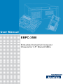
User Manual
EBPC-3500
Embedded Industrial Computer
Chassis for 3.5” Biscuit SBCs
Copyright
The documentation and the software included with this product are copyrighted 2008
by Advantech Co., Ltd. All rights are reserved. Advantech Co., Ltd. reserves the right
to make improvements in the products described in this manual at any time without
notice. No part of this manual may be reproduced, copied, translated or transmitted
in any form or by any means without the prior written permission of Advantech Co.,
Ltd. Information provided in this manual is intended to be accurate and reliable. However, Advantech Co., Ltd. assumes no responsibility for its use, nor for any infringements of the rights of third parties, which may result from its use.
Acknowledgements
EBPC-3500, PCM-9375, PCM-9380, PCM-9381, PCM-9386 and PCM-9387 are
trademarks of Advantech Co., Ltd. All other product names or trademarks are properties of their respective owners.
On-line Technical Support
For technical support and service, please visit our support website at:
http://www.advantech.com/support
EBPC-3500 User Manual
Part No. 2002350001
Edition 2
Printed in China
July 2008
ii
Safety Instructions
1.
2.
3.
4.
5.
6.
7.
8.
9.
10.
11.
12.
13.
14.
15.
16.
17.
Read these safety instructions carefully.
Keep this user manual for later reference.
Disconnect this equipment from AC outlet before cleaning. Do not use liquid or
spray detergents for cleaning.
For pluggable equipment, the power outlet shall be installed near the equipment
and shall be easily accessible.
Keep this equipment away from humidity.
Put this equipment on a reliable surface during installation. Dropping it or letting
it fall could cause damage.
Do not leave this equipment in an environment unconditioned where the storage
temperature under 0° C (32° F) or above 40° C (104° F), it may damage the
equipment.
The openings on the enclosure are for air convection hence protects the equipment from overheating. DO NOT COVER THE OPENINGS.
Make sure the voltage of the power source is correct before connecting the
equipment to the power outlet.
Place the power cord such a way that people can not step on it. Do not place
anything over the power cord. The voltage and current rating of the cord should
be greater than the voltage and current rating marked on the product.
All cautions and warnings on the equipment should be noted.
If the equipment is not used for long time, disconnect it from the power source to
avoid being damaged by transient over-voltage.
Never pour any liquid into ventilation openings. This could cause fire or electrical shock.
Never open the equipment. For safety reasons, the equipment should be
opened only by qualified service personnel.
If any of the following situations arises, get the equipment checked by service
personnel:
a. The power cord or plug is damaged.
b. Liquid has penetrated into the equipment.
c. The equipment has been exposed to moisture.
d. The equipment does not work well or you cannot get it to work according to
user manual.
e. The equipment has been dropped and damaged.
f. The equipment has obvious signs of breakage.
CAUTION: The computer is provided with a battery-powered real-time clock circuit. There is a danger of explosion if battery is incorrectly replaced. Replace
only with same or equivalent type recommended by the manufacture. Discard
used batteries according to the manufacturer's instructions.
THE COMPUTER IS PROVIDED WITH CD DRIVES COMPLY WITH APPROPRIATE SAFETY STANDARDS INCLUDING IEC 60825.
CLASS 1 LASER PRODUCT
KLASSE 1 LASER PRODUKT
iii
EBPC-3500 User Manual
18. This device complies with Part 15 of the FCC rules. Operation is subject to the
following two conditions:
(1) this device may not cause harmful interference, and
(2) this device must accept any interference received, including interference
that may cause undesired operation.
19. CAUTION: Always completely disconnect the power cord from your chassis
whenever you work with the hardware. Do not make connections while the
power is on. Sensitive electronic components can be damaged by sudden
power surges.
20. CAUTION: Always ground yourself to remove any static charge before touching
the motherboard, backplane, or add-on cards. Modern electronic devices are
very sensitive to static electric charges. As a safety precaution, use a grounding
wrist strap at all times. Place all electronic components on a static-dissipative
surface or in a static-shielded bag when they are not in the chassis.
21. CAUTION: Any unverified component could cause unexpected damage. To
ensure the correct installation, please always use the components (ex. screws)
provided with the accessory box.
Safety Precaution - Static Electricity
Follow these simple precautions to protect yourself from harm and the products from
damage.
1. To avoid electrical shock, always disconnect the power from your PC chassis
before you work on it. Don't touch any components on the CPU card or other
cards while the PC is on.
2. Disconnect power before making any configuration changes. The sudden rush
of power as you connect a jumper or install a card may damage sensitive electronic components.
EBPC-3500 User Manual
iv
A Message to the Customer
Advantech customer services
Each and every Advantech product is built to the most exacting specifications to
ensure reliable performance in the harsh and demanding conditions typical of industrial environments. Whether your new Advantech equipment is destined for the laboratory or the factory floor, you can be assured that your product will provide the
reliability and ease of operation for which the name Advantech has come to be
known. Your satisfaction is our primary concern. Here is a guide to Advantech's customer services.
To ensure you get the full benefit of our services, please follow the instructions below
carefully.
Technical support
We want you to get the best performance possible from your products. If you run into
technical difficulties, we are here to help. For the most frequently asked questions,
you can easily find answers in your product documentation. These answers are normally a lot more detailed than the ones we can give over the phone.
Please consult this manual first. If you still cannot find the answer, gather all the information or questions that apply to your problem, and with the product close at hand,
call your dealer. Our dealers are well trained and ready to give you the support you
need to get the most from your Advantech products. In fact, most problems reported
are minor and can be easily solved over the phone.
In addition, free technical support is available from Advantech engineers every business day. We are always ready to give advice about application requirements or specific information on the installation and operation of any of our products.
v
EBPC-3500 User Manual
Product Warranty (2 years)
Advantech warrants to you, the original purchaser, that each of its products will be
free from defects in materials and workmanship for two years from the date of purchase.
This warranty does not apply to any products which have been repaired or altered by
persons other than repair personnel authorized by Advantech, or which have been
subject to misuse, abuse, accident or improper installation. Advantech assumes no
liability under the terms of this warranty as a consequence of such events.
Because of Advantech’s high quality-control standards and rigorous testing, most of
our customers never need to use our repair service. If an Advantech product is defective, it will be repaired or replaced at no charge during the warranty period. For outof-warranty repairs, you will be billed according to the cost of replacement materials,
service time and freight. Please consult your dealer for more details.
If you think you have a defective product, follow these steps:
1. Collect all the information about the problem encountered. (For example, CPU
speed, Advantech products used, other hardware and software used, etc.) Note
anything abnormal and list any onscreen messages you get when the problem
occurs.
2. Call your dealer and describe the problem. Please have your manual, product,
and any helpful information readily available.
3. If your product is diagnosed as defective, obtain an RMA (return merchandise
authorization) number from your dealer. This allows us to process your return
more quickly.
4. Carefully pack the defective product, a fully-completed Repair and Replacement
Order Card and a photocopy proof of purchase date (such as your sales receipt)
in a shippable container. A product returned without proof of the purchase date
is not eligible for warranty service.
5. Write the RMA number visibly on the outside of the package and ship it prepaid
to your dealer.
Initial Inspection
When you open the carton, please make sure that the following materials have been
shipped:
! EBPC-3500 Chassis
! User Manual
! Warranty Card
!
Accessory box with a package of screws (for fastening the SBC, 3.5" disk drive,
mounting brackets, etc.), 4 pcs of rubber pads, a pair of mounting brackets and
a label for the pre-punched I/O ports.
If any of these items are missing or damaged, contact your distributor or sales representative immediately. We have carefully inspected the product mechanically and
electrically before shipment. It should be free of marks and scratches and in perfect
working order upon receipt. As you unpack the product, check it for signs of shipping
damage. (For example, damaged box, scratches, dents, etc.) If it is damaged or it
fails to meet the specifications, notify our service department or your local sales representative immediately. Also, please notify the carrier. Retain the shipping carton
and packing material for inspection by the carrier. After inspection, we will make
arrangements to repair or replace the unit.
EBPC-3500 User Manual
vi
Contents
Chapter
1
General Information ............................1
1.1
1.2
1.3
Introduction ............................................................................................... 2
Specification.............................................................................................. 3
Power Supply ............................................................................................ 3
Table 1.1: Power supply .............................................................. 3
Environment Specifications....................................................................... 3
Dimensions of EBPC-3500 ....................................................................... 4
Figure 1.1 Dimension Diagram of EBPC-3500 ............................ 4
1.4
1.5
Chapter
2
System Setup .......................................5
2.1
Removing the Chassis Cover.................................................................... 6
Figure 2.1 Removing the top cover.............................................. 6
Installing the Compact Flash or Mini PCI Module .................................... 7
Figure 2.2 Removing the bottom cover to maintain the compact
flash or mini PCI module ............................................ 7
Installing the 3.5” Biscuit SBC................................................................... 8
Figure 2.3 Installing a SBC .......................................................... 8
Installing a PCI-104 or MIO Module .......................................................... 9
Figure 2.4 Installing the PCI-104 module .................................... 9
Figure 2.5 Installing a MIO module.............................................. 9
Installing the Disk Drive........................................................................... 10
Figure 2.6 Installing the 2.5” HDD ............................................. 10
Attaching the Mounting Brackets ............................................................ 11
Figure 2.7 Attaching the mounting brackets .............................. 11
2.2
2.3
2.4
2.5
2.6
Chapter
3
I/O Board, Optional Display Module Kit
and Cable Connections13
3.1
3.4
I/O Board Layout ..................................................................................... 14
Figure 3.1 I/O board layout ....................................................... 14
Table 3.1: Cable Connections between PCM-9375E and rear I/O
Board (for EBPC-3500-75CE) .................................. 14
Table 3.2: Cable Connections between PCM-938X and rear I/O
Board (for EBPC-3500-80CE) .................................. 16
Jumper Setting for Rear COM Mode (RS-232/422/485) ......................... 18
Table 3.3: Jumper Setting for COM Mode (RS-232/422/485) on
the I/O Board ............................................................ 18
Figure 3.2 JP1 and JP2 jumper setting for RS-232 mode ......... 18
Figure 3.3 JP1 and JP2 jumper setting for RS-422/RS-485 mode
19
Optional Display Module Layout ............................................................. 19
Figure 3.4 Display module layout .............................................. 19
Cables Connection between the SBC and the Display Module .............. 20
4
Operation............................................21
4.1
The Front Plate ....................................................................................... 22
Figure 4.1 Front plate of EBPC-3500-75CE .............................. 22
Figure 4.2 Front plate of EBPC-3500-80CE .............................. 22
The Rear Plate ........................................................................................ 22
3.2
3.3
Chapter
4.2
vii
EBPC-3500 User Manual
4.3
4.4
Figure 4.3 Rear plate................................................................. 22
Replacing the Cooling fan....................................................................... 23
Figure 4.4 Replacing the system fan ......................................... 23
Replacing the Power Board .................................................................... 24
Figure 4.5 Replacing the power board ...................................... 24
Appendix A
Exploded Diagram ............................ 25
A.1
Exploded Diagram .................................................................................. 26
Figure A.1 Exploded Diagram.................................................... 26
Table A.1: Parts List .................................................................. 26
Appendix B
3.5” Biscuit SBC Options ................. 27
B.1
3.5” Biscuit SBC Options ........................................................................ 28
Table B.1: 3.5” Biscuit SBC Options.......................................... 28
EBPC-3500 User Manual
viii
Chapter
1
1
General Information
This chapter provides general
information about the EBPC-3500.
Sections include
! Introduction
! Specifications
! Power supply
! Environment Specifications
! Dimensions Diagram
1.1 Introduction
The EBPC-3500 series is a rugged and compact advanced embedded industrial
computer chassis. It is designed specifically for 3.5" biscuit SBCs.
Universal, comprehensive and flexible I/O expansion features
! Built-in is an I/O board that carries common I/O ports out and access from chassis externally
! Easily customized front plate to suit various of 3.5” biscuit SBCs
! Abundant pre-punched I/O ports on the rear plate for various I/O ports demands
! Flexibility to expand the I/O ports by adding a PC/104, PC/104+, PCI-104 or
MIO interface modules
Wide range of DC power inputs, ATX supported
! The EBPC-3500 series embedded chassis allows a wide range power inputs
from DC 12 V ~ 24 V, it also supports ATX which offers system integrators the
flexibility and excellent power management for various embedded application
environments.
Compact and robust construction
! Robust and heavy-duty metal cast construction.
! Modular design offers maximum space efficiency and good electromagnetic
compatibility.
! A specially cushioned design that absorbs vibration from 2.5” HDD to ensure
maximum reliability
Highly scalable performance with Low Power Consumption
! Scalable Low Voltage and Ultra Low Voltage Pentium M class processor system
to bring high computing performance with low power consumption.
Optimal integration
! Simple, modular and friendly design
! Quick installation, easy expansion and maintenance
! Product longevity support to secure investment value
EBPC-3500 User Manual
2
!
!
!
!
!
1.3 Power Supply
The EBPC-3500 accommodates an DC 46 W ATX power board. The detail spec is as
below.
Table 1.1: Power supply
Part Number
9898025700E
Output rating
46 W max.
Power source
12 ~ 24 VDC
Input voltage
12 VDC @ 4.5 A, 16 VDC @ 3.4 A,
19 VDC @ 2.9 A, 24 VDC @ 2.3 A
Output voltage
+5 VDC @ 7 A, +12 VDC @ 0.5 A, +5 VSB @ 1 A
Power input connector
2-pole Phoenix DC power connector
1.4 Environment Specifications
!
!
!
!
Temperature:
(Operating) 0 to 40° C (32 to 104° F)
(Non-Operating) -20 to 60° C (-4 to 140° F)
Relative Humidity: 0% ~ 95% (non-condensing)
Vibration During Operation:
1Grms (5 ~ 500 Hz)
Shock During Operation:
20G with 11ms duration, half-sine wave
3
EBPC-3500 User Manual
General Information
!
!
!
Construction: Heavy-duty steel
Disk Drive Capacity: One internal 2.5” disk drive bay
LED Indicators on front panel: Single-color LED for Power (green) and HDD
activity (red).
Front I/O Interfaces: A mini DIN PS/2 port, a 9-pin D-SUB COM port, a VGA
port, a 10/100 LAN port, a USB port (EBPC-3500-80CE only)
Rear I/O Interfaces: Built-in parallel port, DIO port, COM port, LAN port, two
USB ports, a Line in jack, a Line out jack and a Mic-in jack. An LVDS and an
inverter pre-punched openings reserved for the display module kit. A prepunched DVI, 2 USB and two 9-pin DSUB openings.
Cooling System: one 40 cm x 40 cm (11.4 CFM) cooling fan
Weight: 1 Kg (2.2lb)
Dimensions (W x H x D): 230 x 70 x 175 mm (9.1" x 2.8" x 6.9")
Chapter 1
1.2 Specification
1.5 Dimensions of EBPC-3500
Unit: mm [inch]
Figure 1.1 Dimension Diagram of EBPC-3500
EBPC-3500 User Manual
4
Chapter
2
2
System Setup
This chapter introduces the installation process.
Sections include:
! Removing the chassis cover
! Installing the compact flash and
mini PCI module
! Installing the 3.5” SBC
! Installing the PCI-104 or MIO
module
! Installing the 2.5” disk drive
! Attaching the mounting bracket
The following procedures will instruct you to install a 3.5” SBC, PCI-104 module, MIO
module and disk drive into the chassis.
Note!
Use caution when installing or operating the components with the chassis open. Be sure to turn off the power, unplug the power cord and
ground yourself by touching the metal chassis before you handle any
components inside the machine.
2.1 Removing the Chassis Cover
To remove the chassis cover, please proceed as below.
1. Loosen two screws on the bottom of the top cover.
2. Loosen two screws on right and left side of the top cover.
3. Pull forwards the top cover and then lift it up. (see Figure 2.1)
Figure 2.1 Removing the top cover
EBPC-3500 User Manual
6
It’s better to insert the compact flash or mini PCI module into the socket on the SBC
first if it’s necessary. After the SBC has been installed into the chassis, then users
need to open the bottom cover of the chassis by loosening the 4 screws to install or
replace the compact flash or mini PCI module. (Figure 2.2)
The compact flash is allocated as Secondary IDE Master.
Figure 2.2 Removing the bottom cover to maintain the compact flash or mini
PCI module
7
EBPC-3500 User Manual
System Setup
Note!
Chapter 2
2.2 Installing the Compact Flash or Mini PCI
Module
2.3 Installing the 3.5” Biscuit SBC
The EBPC-3500 supports Advantech PCM-9375E and PCM-938X series (except
PCM-9382) of 3.5” SBCs. To install the SBC, please proceed as follows: (Figure 2.3)
1. Install the CPU, CPU cooler, RAM, CF card, mini PCI module, etc. on the SBC.
2. Remove the hexangular copper stubs on the VGA port & 9-pin D-SUB port.
3. Fasten the SBC onto the chassis with the screws provided.
4. Find the 4 hexangular copper stubs in the accessory box. Then fasten them
onto the VGA port & 9-pin D-SUB port.
5. Connect the cables provided from the front I/O board to the SBC, (see the detail
cable connection on Chapter 3)
6. Connect the 12-pin (or 4-pin) power connector from the power board to the
SBC.
7. Connect the power LED, HDD LED and power switch wire from the chassis to
the SBC.
Figure 2.3 Installing a SBC
EBPC-3500 User Manual
8
The EBPC-3500 supports PCI-104 or MIO modules depending on the SBC specification. To install the module, just simply insert the module to the corresponding slot as
follows:
Note!
Figure 2.4 Installing the PCI-104 module
Figure 2.5 Installing a MIO module
9
EBPC-3500 User Manual
System Setup
Use caution when installing a PCI-104 or MIO module, please note the
height limit. It may cause a mechanical obstacle if some components on
the PCI-104 or MIO modules are too high.
Chapter 2
2.4 Installing a PCI-104 or MIO Module
2.5 Installing the Disk Drive
The EBPC-3500 comes with a shockproof bracket for an internal 2.5” HDD. Please
refer to the following instructions to install the 2.5” hard disk drive.
1. To install the 2.5” internal HDD, remove the bottom cover by releasing the four
screws. (see Figure 2.6)
2. The bottom cover is with the HDD bracket mounted. Insert the disk drive into the
proper location of the bracket and secure them with the screws provided.
3. Connect the 44-pin IDE cable from the SBC.
4. Return the bottom cover with the 2.5” HDD in the original position and fasten it
with the four screws.
Figure 2.6 Installing the 2.5” HDD
EBPC-3500 User Manual
10
There is a pair of mounting brackets in the accessory box. If you need to install them,
please refer to Figure 2.7 to simply fasten them to the bottom-left and bottom-right of
the chassis with the four screws provided.
Chapter 2
2.6 Attaching the Mounting Brackets
System Setup
Figure 2.7 Attaching the mounting brackets
11
EBPC-3500 User Manual
EBPC-3500 User Manual
12
Chapter
3
3
I/O Board, Optional
Display Module Kit and
Cable Connections
This chapter introduces the I/O
board, display module kit and
cable connections.
Sections include:
! I/O board layout
! Cable connections between the
3.5” SBC & I/O board
! Optional display module layout
! Cable connections between the
SBC & the display module kit
3.1 I/O Board Layout
The layout of the rear I/O board is given below:
CN1
CN2
CN12
CN9
CN6
CN5
CN10
Figure 3.1 I/O board layout
Table 3.1: Cable Connections between PCM-9375E and rear I/O Board
(for EBPC-3500-75CE)
Illustration
EBPC-3500 User Manual
Rear I/O
Board
Part Number
PCM-9375E
Function
1700001394
-
DC connector converter
1700002172
CN13
USB
Rear plate
1700002281
CN11
44-pin IDE
flat cable
-
1700002283
CN22
Audio
CN9
14
Illustration
PCM-9375E
Function
Rear I/O
Board
1700002284
CN24
LAN
CN12
1700002285
CN16, CN8
COM
CN2,
rear plate
1700008721
CN15
USB
CN10
1700002286
CN1, CN2
Power cable
CN2
(power
board)
1700002287
CN17
LPT
CN1
1700002295
CN9
DIO
CN6
1700007374
CN8
Power switch Rear plate
15
EBPC-3500 User Manual
I/O Board, Optional Display Module Kit and Cable Connections
Part Number
Chapter 3
Table 3.1: Cable Connections between PCM-9375E and rear I/O Board
(for EBPC-3500-75CE)
Table 3.2: Cable Connections between PCM-938X and rear I/O Board (for
EBPC-3500-80CE)
Illustration
EBPC-3500 User Manual
Rear I/O
Board
Part Number
PCM-938X
Function
1700001394
-
DC connector converter
1700002275
CN2
Audio
CN9
1700002277
CN8
COM
CN2
1700002278
CN13
LPT
CN1
1700002279
CN7
(PCM-9380
only)
DIO
CN6
1700002280
CN3
CN2
Power cable (power
board)
1700002281
CN4
44-pin IDE
flat cable
16
-
Illustration
PCM-938X
Function
Rear I/O
Board
1700008721
CN5
USB
CN10
1700007132
CN7
(PCM-9387
only)
DIO
CN6
1700007374
CN16
Power switch Rear plate
1700008401
CN10
LED
CN5,
rear plate
Note: DIO Pin Definitions:
CN6
(internal)
Pin
CN7
(D-SUB)
CN6
(internal)
Pin
CN7
(D-SUB)
Vcc
1
DIO0
DIO3
9
X
GND
DIO4
2
DIO1
10
X
DIO0
3
DIO2
11
Vcc
DIO5
4
DIO3
12
Vcc
DIO1
5
DIO4
13
GND
DIO6
6
DIO5
14
GND
DIO2
7
DIO6
15
GND
DIO7
8
DIO7
17
EBPC-3500 User Manual
I/O Board, Optional Display Module Kit and Cable Connections
Part Number
Chapter 3
Table 3.2: Cable Connections between PCM-938X and rear I/O Board (for
EBPC-3500-80CE)
3.2 Jumper Setting for Rear COM Mode (RS-232/
422/485)
The COM port located on the rear plate can be configured to operate in RS-232, RS422 or RS-485 mode. It is not only set by the SBC but also set by the I/O board.
Please refer to the table as below to set the jumper, JP1 and JP2, to meet the mode
you need. (Please refer to the setting on the SBC by reading the PCM user manual.)
Table 3.3: Jumper Setting for COM Mode (RS-232/422/485) on the I/O
Board
Mode
Setting
RS-232 (default)
JP1 and JP2 (1-2 closed, 4-5 closed)
RS-422
JP1 and JP2 (2-3 closed, 5-6 closed)
RS-485
JP1 and JP2 (2-3 closed, 5-6 closed)
JP2 JP1
Figure 3.2 JP1 and JP2 jumper setting for RS-232 mode
EBPC-3500 User Manual
18
Chapter 3
JP2 JP1
Figure 3.3 JP1 and JP2 jumper setting for RS-422/RS-485 mode
3.3 Optional Display Module Layout
The layout of the optional display module is given below:
Inverter CN5
LVDS CN1
Figure 3.4 Display module layout
19
EBPC-3500 User Manual
I/O Board, Optional Display Module Kit and Cable Connections
JP2 JP1
3.4 Cables Connection between the SBC and the
Display Module
Illustration
EBPC-3500 User Manual
Part Number
PCM-9375E
PCM-938X
Function
Display
Module
1700000410
CN23
(PCM-9381/
87 only)
DVI
Rear plate
1700002289
CN1
(PCM-9380/
81/86/87)
LVDS
CN1
1700002297
CN4
(PCM-9375
only)
LVDS
CN1
1700002288
CN17
(PCM-9380/
81/86/87)
Inverter
CN5
1700002282
CN5
(PCM-9375
only)
Inverter
CN5
20
Chapter
4
4
Operation
This chapter introduces how to
initialize the EBPC-3500.
Sections include:
! The front plate
! The rear plate
! Replacing the cooling fan
! Replacing the power board
4.1 The Front Plate
The front panel features a COM, a LAN, a mini DIN PS/2, a VGA, and a single USB
(for EBPC-3500-80CE only) opening. There is also a system reset button and two
LEDs. When the system power is on, the POWER LED is always Green. When the
HDD LED is blinking Red, it means the HDD is transmitting data. Moreover, it provides a pre-punched area for PCI-104 or MIO module expansion.
Figure 4.1 Front plate of EBPC-3500-75CE
Figure 4.2 Front plate of EBPC-3500-80CE
4.2 The Rear Plate
The rear plate features a Line-in jack, a Line out jack, a Mic-in jack, a LAN port, two
USB ports, a 25-pin D-SUB parallel port, a 9-pin D-SUB COM port, and one DIO port.
It reserves a LVDS and an Inverter openings for the optional display module kit. It
also reserves two 9-pin DSUB, a dual USB and a DVI opening. The momentary ATX
power switch is on the rear plate, so it can avoid being touched by accident.
Figure 4.3 Rear plate
EBPC-3500 User Manual
22
Figure 4.4 Replacing the system fan
23
EBPC-3500 User Manual
Operation
There is a system cooling fan near the rear of the chassis. To replace the cooling fan,
please follow the procedures as below.
1. Remove the top cover
2. Unplug the fan power connector.
3. Loosen the two screws on the rear plate and take out the fan module. (see Figure 4.4)
4. Remove the two screws on the fan guard.
5. Fasten the fan guard onto a new fan.
6. Return the fan module with the wire downward to the chassis and fasten it with
two screws.
7. Plug in the fan power connector.
8. Replace the top cover and fasten it.
Chapter 4
4.3 Replacing the Cooling fan
4.4 Replacing the Power Board
The EBPC-3500 power is provided by the power board. Connect the EBPC-3500 to a
12~24 VDC power source. The power source can be either from a power adapter or
an in-house power source. To replace the power board, proceed as follows:
1.
2.
3.
4.
5.
6.
Unplug the DC adapter from the chassis.
Remove the top cover.
Unplug the 10-pin power connector from the power board.
Fasten a new power board onto the chassis.
Plug the 10-pin power connector to the power board.
Return the top cover and fasten it, finally plug in the DC adapter.
Figure 4.5 Replacing the power board
EBPC-3500 User Manual
24
Appendix
A
A
Exploded Diagram
A.1 Exploded Diagram
Figure A.1 Exploded Diagram
Table A.1: Parts List
1. MIO module I/O cover
2. FRONT I/O COVER
3. CHASSIS
4. TOP COVER
5. HDD BRACKET
6. RUBBER CUSHION
7. SPRING
8. BOTTOM COVER
9. WASHER
10. FAN GUARD
11. SYSTEM COOLING FAN 12. POWER BOARD
13. I/O BOARD
14. POWER SWITCH
EBPC-3500 User Manual
26
Appendix
B
B
3.5” Biscuit SBC
Options
This appendix shows the 3.5" SBC
options.
B.1 3.5” Biscuit SBC Options
EBPC-3500 supports a variety of Advantech 3.5” biscuit SBCs as below. Users can
contact a local sales representative for detailed information.
Table B.1: 3.5” Biscuit SBC Options
Slot
Model Name
CF
PCI-104
PC/104
MIO
PCM-9375E
1
-
V
-
PCM-9380
1
-
-
V
PCM-9381
1
V
-
-
PCM-9386
1
-
-
V
PCM-9387
1
V
-
-
EBPC-3500 User Manual
28
Appendix B 3.5” Biscuit SBC Options
EBPC-3500 User Manual
29
www.advantech.com
Please verify specifications before quoting. This guide is intended for reference
purposes only.
All product specifications are subject to change without notice.
No part of this publication may be reproduced in any form or by any means,
electronic, photocopying, recording or otherwise, without prior written permission of the publisher.
All brand and product names are trademarks or registered trademarks of their
respective companies.
© Advantech Co., Ltd. 2008