1
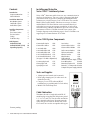
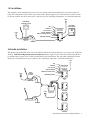
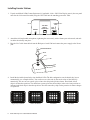
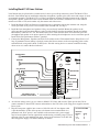
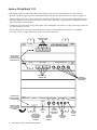
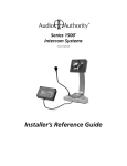
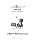
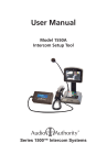
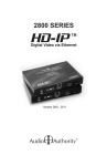
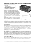
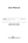
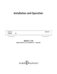
PATENTS PENDING
Series 1500™
Intercom Systems
Contents
Introduction
Component Overview
Cable Fabrication
2
2
2
Installation Overview
One-On-One System
Small Audio System
Audio/Video System
3
3
4
Installing Components
The Hub
The Counter Station
The Lane Station
Testing
Troubleshooting
5
6
7
8
8
Hub Diagrams
Audio Hub (1509)
Audio/Video Hub (1510)
Expanding Capacity
9
10
11
Installing and Using the
Series 1500™ Intercom Systems
Series 1500™ Intercoms enable clear two-way communications in
retail service businesses. Two-way video is integrated with highperformance audio to provide a complete intercommunication
solution over a single Category 5e or 6 UTP cable. The versatile
Model 1500 Counter Station, which can access up to 16 lanes,
and the Model 1520 Lane Station can be connected directly to
each other in a one-on-one system, or multiples of each can be
networked using a Model 1509 Hub for up to two-on-four audio
performance or Series 1510 Hub for multi-lane systems (See
example diagrams on the following pages). Series 1510 Hubs can
support up to 8 Counter Stations on 16 lanes.
Series 1500 System Components
Counter Audio Station
Counter Video Add-on
1500
1502
2-on-4 Audio Hub
1509
4-on-4 Audio/Video Hub
1510
4-on-8 Audio/Video Hub
1511
8-on-12 Audio/Video Hub 1512
8-on-16 Audio/Video Hub 1513
(See page 11 for Hub configurations)
4-counter plug-in card
4-lane plug-in card
System plug-in card
1515
1516
1517
Lane Station
Customer Video Station
Customer Video Add-On
1520
1522
1523
Surface-mount handset
Flush-mount handset
Wireless headset
Wired headset
Field Setup LCD
Universal 1A Power Supply
Boom Microphone
External microphone kit
External 3”, 4 ohm speaker
3 Amp UL DC power supply
1540
1541
1542
1543
1550
571-013
631-026
631-029
631-030
805-016
Tools and Supplies
RJ45
WHT / ORN
ORN
WHT / GRN
BLU
WHT / BLU
GRN
WHT / BRN
BRN
• 18mm open-end wrench (for boom mic)
• RJ-45 plug crimping tool (if cables are to be
fabricated on-site)
• Category 5e or 6 UTP cable and RJ-45
terminations (or prefabricated Cat 5e/6 cables)
• Model 1550 Field Setup Tool
Terminate the ends of each cable with RJ-45
modular plugs using the EIA 568 pinout (paired
1-2, 3-6, 4-5, and 7-8). Test the cable assemblies
with a network cable tester. Pre-made network
cables may also be used for shorter runs. Note:
Cat 5e and Cat 6 are also acceptable cable types.
Patents pending.
2
Audio Authority Series 1500 Installation Manual
CATEGORY 5,
5e or 6 CABLE
Cable Fabrication
1x1 Installation
The simplest system configuration involves only one counter station connected directly to one lane station (no
hub). This configuration can be audio-only or audio/video. Run a length of Cat 5 cable from the counter location
to the lane location; the cable can be up to 1,000 feet long. See “Installing Components” for detailed instructions.
POWER
AUDIO/VIDEO
COUNTER STATION
CUSTOMER
VIDEO ADD-ON
MIC
SPEAKER
LANE STATION
LOCATED IN
DRIVE UP UNIT
CALL BUTTON
TRAFFIC SENSING
POWER
REMOTE CONTROL RELAY
MODEL 1523
ARMORED HANDSET
MODEL 1500
WITH 1502
MODEL
1520
HEADSET
2x4 Audio Installation
The Model 1509 Audio Hub allows one or two Model 1500 Audio Counter Stations to serve up to four 1520 Lane
Stations. 1509 Hub configurations must be audio-only. Run a length of Cat 5 cable from each Counter Station
to the Hub. Run a length of Cat 5 cable from the Hub to each Lane Station. The total cable length from Counter
Station to Lane Station can be up to 1,000 feet. See “Installing Components” for detailed instructions.
POWER
MIC
SPEAKER
CALL BUTTON
LANE STATION
LOCATED IN
DRIVE UP UNIT
TRAFFIC SENSING
POWER
REMOTE CONTROL RELAY
AUDIO
COUNTER
STATION
ARMORED HANDSET
MODEL
1520
MODEL 1500
HEADSET
POWER
AUDIO HUB
MODEL 1509
HEADSET
Audio Authority Series 1500 Installation Manual
3
4x4 Audio/Video Installation
The Audio/Video Hub configurations allow from one to as many as eight Counter Stations to serve up to 16 Lane
Stations. These configurations (1510, 1511, 1512 and 1513) may be audio-only or audio/video. Run a length of
Cat 5 cable from each Counter Station to the Hub. Run a length of Cat 5 cable from the Hub to each Lane Station.
The total cable length from Counter Station to Lane Station can be up to 1,000 feet. See “Installing Components”
for detailed instructions.
POWER
CUSTOMER
VIDEO ADD-ON
MIC
SPEAKER
CALL BUTTON
LANE STATION
LOCATED IN
DRIVE UP UNIT
TRAFFIC SENSING
REMOTE CTRL RELAY
MODEL 1523
ARMORED HANDSET
POWER
MODEL
1520
EXISTING
CAMERA
AUDIO/VIDEO
COUNTER
STATION
HEADSET
AUDIO/VIDEO HUB
TYPICALLY LOCATED IN
TELEPHONE CLOSET OR
UNDER A COUNTER
MODEL 1510
EXISTING
VIDEO
DISPLAY
HEADSET
POWER
SINGLE CAT 5 CABLE
COAX (RG59)
AUDIO OR OTHER WIRE
FROM HUB CAMERA OUTPUTS
TO SECURITY VIDEO RECORDER
FROM DVD or PC* AUDIO/VIDEO
TO HUB PROGRAM INPUTS
SURVEILLANCE CAMERA OUTPUT
TO HUB WIDEANGLE CAMERA INPUT
Illustration: Two Counter Stations serve Four Lane Stations. Counter Stations and Lane Stations may have video
capability, or be audio-only. One Lane Station is shown with a Model 1523 Video Add-On; alternatively, any 1520
may be connected to existing camera and video display.
If desired, any 1520 could be replaced by a 1522 Customer Video Station, which has all the capability and
connections of a 1520 plus a camera, video display and call button mounted in one enclosure.
* PC video output signals may need to be modified for viewing on intercom video displays. Call Audio Authority for details.
4
Audio Authority Series 1500 Installation Manual
Installing a 1509 Hub
1. Position and install the Hub under the
counter or in a secure indoor location
such as a telephone closet. Ground the
hub to a nearby electrical device cover
using the green grounding wire attached
to the hub.
2. Run a length of Cat 5 cable from each
counter and lane station to the hub.
Observe the wiring guide on page 2,
and use a cable tester to verify the
terminations.
3. Connect audio source to Program Audio
jacks if desired, and adjust volume level
during system testing.
Illustration: Shown is Model 1509 Audio
Intercom Hub. Minimum connections for
Audio/Video Hubs are shown. For more
information on Memory and Diagnostics
functionality, see page 9.
LEVEL
COUNTER
STATION 1
CAT 5 CABLE TO
COUNTER STATION #1
PROGRAM AUDIO
COUNTER
STATION 2
LANE
STATION 1
CAT 5 CABLE TO
LANE STATION #1
LANE
STATION 2
LANE
STATION 3
LANE
STATION 4
12 VOLT
DC POWER
MEMORY
DIAGNOSTICS
1 AMP POWER SUPPLY
(MODEL 571-013)
GROUND WIRE TO ELECTRICAL
DEVICE COVER
Installing a 1510 Hub (1511, 1512, 1513 are similar)
1. Position and install the Hub under the counter or in a secure indoor location such as a telephone closet.
Ground the hub to a nearby electrical device cover using the green grounding wire attached to the hub.
2. If the installation requires additional capacity, install a Counter Card or Lane Card(s) as needed (see page 11).
3. Run a length of Cat 5 cable from each counter and lane station to the hub. Observe the wiring guide on page
2, and use a cable tester to verify the terminations.
4. Connect other equipment as needed (see page 11).
FOUR-UNIT COUNTER STATION
CARD (MODEL 1515)
CAT 5 CABLE TO COUNTER STATION #1
FOUR-UNIT LANE STATION
CARD (MODEL 1516)
CAT 5 CABLE TO LANE STATION #1
GROUND WIRE
SYSTEM CARD (MODEL 1517)
SEE PAGE 10 FOR INSTRUCTIONS
1 AMP POWER SUPPLY
(MODEL 571-013)
POWER CONNECTION
Illustration: Model 1510, the minimum capacity AV Hub configuration. Minimum connections for Audio/Video
Hubs are shown. For more configurations, system card functions, and other connections, see page 11.
Audio Authority Series 1500 Installation Manual
5
Installing Counter Stations
1. Unpack each Model 1500 Counter Station and, if applicable, slide a 1502 Video Display onto it (the rear panel
must first be slid out and discarded). Plug the 1502 cable into the matching port on the 1500.
1502 VIDEO
DISPLAY
CONNECTION
POWER
PACK
CAT 5
CABLE
HEADSET
2. Attach the field-replaceable microphone, tightening the nut securely with a 18mm open end wrench, and tuck
its rubber boot firmly into place.
3. Plug the Cat 5 cable from the hub into the Hub port of each 1500 and connect the power supply to the Power
jack.
MICROPHONE STALK
BOOT
NUT
4. Install the desired keyboard inlays into the Model 1500. The hub configuration sets the default key layout
automatically (see examples below). You can choose to color-code by the carrier color or label the keys
numerically. For one-on-one systems, place a lane color chip in the position shown. Place blank, black
chips in all the other positions. For multi-lane systems, place the desired chips in the active lane positions as
indicated and black chips in the other positions. Save the unused key chips on the premises for future changes
or expansion.
Single Lane (1x1) Default
6
1509 or 1510 Default
Audio Authority Series 1500 Installation Manual
1511 Default
1512 Default
Installing Model 1520 Lane Stations
Lane Stations may be placed at the customer end of a drive-up or walk-up intercom system. The Model 1520 is
the basic Lane Station unit for installations where the microphone, speaker (plus video screen and camera, if used)
are mounted separately. The Model 1522 is a Video Lane Station, including all of the features of the 1520 plus
microphone, speaker, camera and video screen mounted inside one enclosure. The Model 1523 Video Add-on
must be used with a 1520, and contains only the camera and video screen.
1. Install the Model 1520 Lane Station in each deal drawer or pneumatic unit on the customer end, using the
screws provided. If AC power is not available at the customer end, see Step 5.
2. Install the lane microphones and speakers if they are not already installed. Mount the speakers in the
grilles provided in the document delivery units. Peel the backing from the microphone shrouds and adhere
them directly centered over a 1/8” hole drilled in the faces of the customer units. At each station, place the
microphone and speaker as far apart as practical, while centering the microphone to receive customer speech.
Install Teller Call push-button switches, if needed.
3. Connect the Microphones, Speakers and Teller Call switches to the 1520 terminal blocks. Strip all wires 1/4”
long. If pneumatic blower muting is desired, connect the blower contacts to the corresponding points on the
terminal blocks, using small (about 22 AWG) wire. If traffic sensing devices or remote-controlled security
doors are in use, connect them as indicated.
MICROPHONE
SPEAKER
POWER
CALL BUTTON
1
2
TRAFFIC SENSE
3
4
+
–
+
–
MICROPHONE
SPEAKER
5 CALL BUTTON
BLOWER
6 TRAFFIC SENSE
7 BLOWER
8 COMMON
9
10
N.O. CONTACTS
ANY DEVICE TO BE
+
CONTROLLED BY RELAY –
HANDSET
4. At each lane where video is in use, connect a Model 1523 Video Add-on to the Video port on the 1520 or
connect standard 75-ohm NTSC cameras and monitors to the 1520 video jacks. Plug power supplies into the
Power jacks.
Recommended AWG
5. Plug the lane power supplies into a source of 100-260 volts AC. An adapter cable
is provided with the 1520 to allow power to be drawn from a terminal block in a
Maximum
pneumatic unit. If AC power is not available on the customer end, a power supply
Distance
Gauge
may be located indoors and its output leads extended using a suitable gauge of wire as
40 ft
18
shown at right. To power multiple lane units, it may be convenient to use an 805-016
60 ft
16
three amp power supply. Call Audio Authority for details.
100 ft
14
Audio Authority Series 1500 Installation Manual
7
Testing
Check the following locations for successful power-up and connectivity, indicated as follows:
• 1500 Counter Station: All LEDs become dark until keys are pressed
• 1510 Hub System Card: Flashing Green LED
• 1520 Lane Station: Flashing Green LED
Check system operation by selecting each lane and speaking with an assistant at the customer position. Adjust
Lane Microphone and Speaker gains using the Model 1550 Field Setup LCD.
Troubleshooting
Acoustical Coupling
Usually results from the lane speaker and microphone being too close together. This condition could cause
feedback prior to reaching a sufficient volume level. To cure this problem, move them farther apart (at least 18
inches) or put the speaker in a separate enclosure and/or aim it in a different direction. If these solutions do not
correct the problem, reduce the open loop gain.
Operators Hear Their Own Voices
A natural result of the full duplex audio process. If this is objectionable, reducing the open loop gain a little will
help.
The Deal Drawer Sounds Bad
Can be caused by poor acoustic treatment in the deal drawer or acoustic coupling from the customer side to the
teller side. Both of these conditions may be helped by adding foam rubber blocks or sheets to the hollow cavities
in the deal drawer.
Lane Microphone Doesn’t Work
Could be caused by using the wrong kind of microphone (it must be electret condenser) or the polarity being
reversed.
Wind Noise
Can often be eliminated by putting a small plug of 3M Scotchbrite™ in the microphone opening. The Audio
Authority lane microphone has a special foam surround; for optimum results, use Audio Authority microphones
and speakers.
8
Audio Authority Series 1500 Installation Manual
Audio Hub Model 1509
The Model 1509 is a compact audio Hub with a maximum capacity of two Counter Stations serving four Lane
Stations.
PROGRAM AUDIO INPUTS
ALLOW CONTENT TO BE
HEARD AT ALL COUNTER AND
LANE STATIONS
PROGRAM AUDIO
VOLUME LEVEL
ADJUSTMENT
LEVEL
COUNTER
STATION 1
CONNECT COUNTER
STATIONS HERE
PROGRAM AUDIO
COUNTER
STATION 2
LANE
STATION 1
LANE
STATION 2
CONNECT LANE
STATIONS HERE
LANE
STATION 3
LANE
STATION 4
12 VOLT
DC POWER
MEMORY
MEMORY CARD FOR
STORING SYSTEM
SETTINGS AND FIELD
UPGRADES
CONNECT 12V
POWER PACK HERE
DIAGNOSTICS
DIAGNOSTICS
PORT NOT
CURRENTLY
USED
CONNECT GROUND WIRE
TO BUILDING GROUND
Audio Authority Series 1500 Installation Manual
9
Audio or AV Hub Model 1510
• The Model 1510 is an audio/video Hub with a capacity of up to four Counter Stations serving four Lane
Stations. The Hub’s capacity can be expanded in the field by adding Counter and/or Lane cards (see page 11).
• System settings can be stored on a removable, proprietary media card for security or replication purposes, and
firmware upgrades can be performed when necessary. These operations are performed via a Model 1550 Field
Setup Tool and a Counter Station.
• Composite video and stereo analog audio inputs allow multimedia source devices to play advertising content on
any lane whenever it is idle.
• Direct outputs from wide angle camera (dedicated security camera) and/or lane cameras for surveillance
recording. Video is output continuously from each camera connected.
CONNECT COUNTER
STATIONS HERE
1515
1
ACTIVE
2 3 4
1
1
ACTIVE
2 3 4
1
COUNTER
CARD 1
COUNTER STATION
2
3
4
LIGHTS INDICATE
CONNECTIVITY
AND VOICE/VIDEO
COMMUNICATION
1516
LANE STATION
2
3
4
1
SECURITY VIDEO OUTPUT
2
3
4
LANE
CARD 1
CONNECT LANE
STATIONS HERE
FLASHING LIGHT
INDICATES NORMAL
HUB OPERATION
CONNECT POWER
SUPPLY TOWARD
REAR UNDER THE
CABINET
1517
POWER
MEMORY
PROGRAM INPUT
DIAGNOSTICS WIDEVIEW CAMERA
INPUT
OUTPUT VIDEO
AUDIO
LEVEL
NOT
CURRENTLY
USED
MEDIA CARD
SLOT FOR BACKUP
AND UPGRADES
(PROPRIETARY
FORMAT)
10
CONNECT TO
VIDEO RECORDER
OR MONITOR
Audio Authority Series 1500 Installation Manual
CONNECT
TO VIDEO
RECORDER OR
MONITOR
CONNECT
DEDICATED
SECURITY
CAMERA
CONNECT
AUDIO OR AV
SOURCE
SYSTEM
CARD
ADJUST
PROGRAM
AUDIO
VOLUME
Hub Configurations and Capacity
Shown below is the Model 1513 Hub, a maximum capacity configuration; all Counter and Lane Card
slots are filled. Several other configurations are available; contact Audio Authority for details, or visit
www.audioauthority.com.
To increase Counter or Lane Station capacity, remove power from the Hub. Remove the blank faceplate from the
appropriate card slot(s) and insert the new cards carefully, making sure the connections are firmly seated. Insert
the two screws to secure the card, and connect new Lane Stations and/or Counter Stations. Connect power and test
the system.
One other maximum configuration is possible, in which four Counter Stations serve 20 Lane Stations. If a 4x20
configuration is desired, contact Audio Authority for special instructions.
CARD SLOT
OPTIONS
1515
1
ACTIVE
2 3 4
1
COUNTER
CARD 1
COUNTER STATION
2
3
4
FIRST 1515
REQUIRED FOR ALL
CONFIGURATIONS
1515
5
ACTIVE
6 7 8
5
1516
1
ACTIVE
2 3 4
1
1516
5
ACTIVE
6 7 8
5
LANE STATION
6
7
8
5
SECURITY VIDEO OUTPUT
6
7
8
LANE
CARD 2
1516
ACTIVE
9 10 11 12
9
LANE STATION
10
11
12
9
SECURITY VIDEO OUTPUT
10
11
12
LANE
CARD 3
1516
ACTIVE
13 14 15 16
13
LANE STATION
14
15
16
13
SECURITY VIDEO OUTPUT
14
15
16
LANE
CARD 4
1517
COUNTER
CARD 2
COUNTER STATION
6
7
8
LANE STATION
2
3
4
1
SECURITY VIDEO OUTPUT
2
3
4
SECOND 1515 FOR 8
COUNTER STATIONS
– OR –
FIFTH 1516 IN 4X20
CONFIGURATIONS
LANE
CARD 1
FIRST 1516
REQUIRED FOR ALL
CONFIGURATIONS
POWER
MEMORY
PROGRAM INPUT
DIAGNOSTICS WIDEVIEW CAMERA
INPUT
OUTPUT VIDEO
AUDIO
LEVEL
SECOND 1516
FOR 8 LANE
CONFIGURATIONS
THIRD 1516
FOR 12 LANE
CONFIGURATIONS
FOURTH 1516
FOR 16 LANE
CONFIGURATIONS
SYSTEM
CARD
1517
(REQUIRED FOR ALL
CONFIGURATIONS)
Audio Authority Series 1500 Installation Manual
11
2048 Mercer Road, Lexington, Kentucky 40511-1071
Phone: 859/233-4599 • Fax: 859/233-4510
Customer Toll-Free USA & Canada: 800/322-8346
Website: http://www.audioauthority.com
752-465
2/06