1
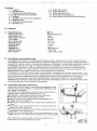
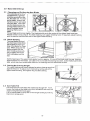
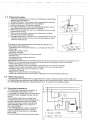
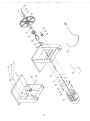
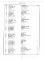
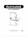
Charnwood, 1 Rowan Street,Leicester, LE3 9GP, England
Tel. 0 1 1 6 2 5 1 1550 Fax. 0116 253 2891
email; sales @charnwood.net.
Contents
• 1.0 General
1.1 Specifications
1.2 User Responsibility/Warranty
1.3 Final Assembly and Installation
2.0 Settings
2.1 Changing and Setting the Sawblade
2.2 Blade Guiding
2.3 Setting the Cutting Height
2.4 Saw Table Tilt
2.5
2.6
2.7
3.0
4.0
Safety Information
Other Information
Electrical Installation
Electrical Wiring Diagrams
Spare Parts List/Exploded View Drawing
1.0
General
1.1
Specifications
Dimensions(lxwxh)
Weight with motor
Table height from floor
Throat width
Max.cutting height
Sawblade length
Sawblade width
Sawtabletilt
Sawtable size
Sawblade speeds
Motor capacity
1.2
User Responsibility/Warranty
This appliance will perform in conformity with the description contained in the instructions provided.
This machine must be checked periodically. Defective epuipment (including power cables) should not
be used. Parts that are broken, missing, obviously worn, distorted or contaminated, should be replaced
immediately. Should such repairor replacement become necessary, it is recommended that only
genuine D&D replacement parts are used and that such repairs are carried out by qualified persons
approved by D&D or its representatives. Failure to comply relieves D&D from product liability. The
aforementioned also applies to all accessories offered for this appliance.
This appliance or any of its parts should not be altered or changed from standard specifications. The
userofthis machine shall have the sole responsibility forany malfunction which results from improper
use or unauthorized modification from standard specifications, faulty maintenance, damage or
improper repair by anyone other than qualified person approved by D&D or its representatives.
Please fill in the warranty registration card and send to the address shown on it. Normal wearing parts
and consumables are not covered by the warranty.
1.3
Final A s s e m b l y a n d I n s t a l l a t i o n
Unpack machine and check for any visible damage which may
have occurred during transport. If a damage is detected notify
your dealer immediately.
This machine is shipped partly disassembled. Saw table and
rip fence guide have to be installed prior to use.
• Remove the rip fence guide extrusion from the table.
• Place the table onto the upper table trunnion.
• Install to trunnion with 4 each serrated lock washer and
• hexagon head screw M 6x16.
• Attach rip fence guide extrusion to table with the two thumb
screws.
• Place table insert into the table centre hole (table insert with
wide slot for bevel cuts only).
• Insert cup square neck screw into rip fence guide and secure
with washer <t>8.4and wing nut.
• Attach rip fence extrusion with 2 each cup square neck screw
M6x30,washer <J>6.4 and knurled nut M6 to the rip fence guide.
W715
860X420X530.mm
35 kg
370 mm
245 mm
100 mm
1712 mm
10 mm
to 45°
340x335 mm
700 m/min
230V 50Hz 370W
After installation adjust the table so that the sawblade runs
through the centre of the table insert's slot.
-1-
Centering the Table
• Loosen the screws holding the lower table trunnion.
• Move table sideways as required, until sawblade runs
through the centre of the table insert.
• Tighten the table trunnion screws, ensure the table stays in
its set position
Setting the Table Square with the Sawblade
• The saw table can be tilted up to 45° .To tilt, loosen the knob
of the table trunnion.
• A stop on the underside of the table rests on the lower
wheel housing when the table is at 90° with the blade.
• By turning the hexagon nut (A) in or out, as required, the
angle against the sawblade can be adjusted.
• After setting the table affix the scale to the rip fence carrier
extrusion.
To ensure sufficient upright stability of the machine it should
be bolted to floor, bench or table, or mounted on the
Workstand BAS, available as optional accessory. For this
purpose <J> 9mm holes are provided in the machine's base
plate.
Sawblade Guard
When opening the lower wheel housing door the
sawblade guard swings down.
When closing the door, the sawblade guard must be lifted
by hand, so the door can close fully.
Important: Operate saw only with the lower wheel
housing door closed.
Dust Collection
If this band saw is operated indoors it is recommended to
have it connected to a dust collector. The suction connector, supplied with the machine, has to be
fitted to the dust ejection port of the saw for this purpose. The diameter of the suction connector is
60 mm. The dust collector this saw is connected to must provide for an air flow rate of 20 mtr/sec.
Caution! Wood dust and chips, together with an ignition source and the oxygen in the ambient air,
can cause fires and explosions, injuries and allergies.
- Workmen working in operations processing oak or beech timber where found to develop more
often cancer of the mucous membrane of the nose (adenocarciome of the inner nose) then other
workers.
- Experience shows that skin contact with oak or beech dust does nor cause cancer.
-2-
2.0
Band Saw Settings
2.1
C h a n g i n g a n d Setting the S a w B l a d e
This band sawis factoryequipped with a general
purpose woodcutting blade, the blade set. To change the blade, remove the
rip fence carrier extrusion
from the table. Then slacken the blade tension by
turning the-handwheel on
top of the upper wheel
housing. Remove the
blade.
Fit new blade and tension lightly. The blade should run in the centre of the rubber lined band saw
wheels or else ir may jump of. To check tracking, turn upper wheel by hand. If required, adjust tracking
with the knurled handle atthe rearof the upperwheel housing.
2.2
Blade Guiding
The saw blades guide of
this band saw model BAS
250 ensure an exact guiding of the blade for clean
cuts. When using narrow
blades ensure that the
lower blade guide positively supports the blade
from both sides and the
rear.
Set the bearings of the upper blade guide to within approx. 0.5 mm of the blade, and the rear bearing
against the back of the blade , just clear of it. Do not set the bearing too close, as the friation generates
heat, which may have an adverse effect on the bearings and the saw blade as-well.
2.3
Setting the Cutting Height
The upper blade guide should always be setas close as practical
against the work. To adjust, turn the knob nut at the side of the
upperwheel housing, and Tighten wig nut after setting.
•
2.4
S a w Table Tilt
For bevel cuts the saw table tilts steplessly through 4 5 ° . To tilt,
loosen the knob on the table trunnions, set table to the required
angle and tighten the knob again.
It is recommended to verify the correct angle setting by making
trial cuts in scrap wood.
llfi
2.5 Safety Information
1. Check that all guards are in place and securely locked before
switching the machine on.
2. Always disconnect from power when servicing this machine.
3. Do not use bent or cracked band saw blades.
4. Replace table insert if slot has enlarged.
5. For cutting operations with a tilted table the rip fence has to
be located to the right hand side of the blade.
6. When cutting round stock use a suitable jig or fixture to keep
the work from turning.
7. When cutting boards in an upright position use a suitable
push block to prevent kickback.
8. To keep health risk to a minimum it is recommended to always
connect this band saw to a dust collector having an air flow
rate of at least 20 m/s.
The most common hazards associated with the operation of
band saws are the following:
- a hazard by the running saw blade, e.g. contact with the teeth
of the blade.
- flinging of cutoffs or knots
- workpiece kickback
The principal hazard areas of a band saw are:
- the work area
- the area around a running machine
- the kickback area
Despite the use of the specific safety devices and compliance with all relevant regulations for the
prevention of accidents, when operating a band saw the following residual risks remain:
- hearing damage by excessive noise;
-dangerof accidents in the unprotected cutting area of the running saw blade;
- dangerof injury when changing blades (danger of cuts by the sharp teeth );
-endangering by flung about workpieces or parts;
- squashing of fingers;
- danger of injury by kickback of workpieces;
- health risk caused by the dust emission, especially from oak and beech saw dust.
2.6
Other Information
This band saw can be fitted and/or upgraded with a range of optional accessories. D&D or its
representatives can only assume liability underthe current product liability regulations if the machine,
and all accessories offered or made available for it, is used for its intended purpose.
2.7
Electrical Installation
This band saw is equipped with either a
0.37 kW230Vsingle-phase,motor.
Connection to a supply circuit is made by an
extension cable, plugged directly into the
switch.
This machine must be connected to an
earthed outlet and should be operated on a
residual current device (RCD) of 30mA
capacity. Extension cables must should
have a minimum lead cross section of
3x0.75mm (230V).
Have damaged power cables replaced at
once by a qualified electrician. Risk of
electric shock if operated with admaged
power cable.
Children should not operate this band saw.
J
RBS-IO
1: S w i t c h :
2: M o t o r :
-4-
KJD20
YYL7114
Cedar Court, Walker Rd
Bardon Hill, Leicestershire
LE671TU ENGLAND
-6-
PARTS LIST
Item Part No.
1
31503031
2
31503022
3
31503032
4
31503020
5
DJ250B04001
6
31503033
7
31503030
8
GB862.2-87 6
9
GB5783-86 M6xl0
10 DJ250B03001
11 DJ250A05001
12 GB894.1-86 10
13 GB/T276-94 6000-2Z
14 DJ250A03005
15 DJ250A03005-1
16 DJ250A04009
17 DJ250A03004A
18 GB896-86
19 DJ250A03007
20 DJ250A03003A
21 GB6177-86 M6
22 DJ250A03002A
23 GB819-85 M4xl2
24 KJD20
25 DJ25005004B
26 GB862.2-87 4
27 GB823-88 M4x6
28 DJ250A03010
29 DJ250B01000
30 DJ250A05002
31 DJ250A03008
32 GB6172-86 M8
33 DJ250A03006
34 GB97.1-85 6
35 GB5783-86 M6xl2
36 GB5783-86 M8x45
37 31503007
38 GB97.1-85 8
39 GB97.1-85 10
40 DJ250A03009
41 DJ250A03011
42 GB/T1792 A16
Description
Slotted Insert
Washer
Housing
Washer
Door Lower
Housing with Nut
Tongue
Ext.Lock Washer 6
Hex.Hd.BoltM6xl0
Door Upper
Saw Blade
Ring Retaining
Ball Bearing
Upper Wheel
Balance Collar
Band Saw Tyre
Bearing Bolt Upper
"E"Rings
Pin Guide
Seat Bearing Bolt Upper
Hex.Hd.Flange Nut
Guide Plate Assembly
Cross Countorsunk HD. Screw
Magnetic Switch
Switch Plate
Ext.Lock Washer
Cross Pan.Hd. Screw
Blade Tensioner
Band Saw Frame
Lamello Plug Black
Adjust Handle
Hex.Hd.ThinNut
Thread Bolt
Washer
Hex.Hd.Bolt
Hex.Hd.Bolt
Wing knob
Washer
Washer
Nut
Shaft
Butterfly Spring
Q'ty
3
3
3
3
1
3
3
3
5
1
1
2
4
1
fit
2
1
2
1
1
8
1
2
1
1
2
2
1
1
1
2
4
1
8
9
1
1
10
1
1
1
18
PARTS LIST
Item
43
44
45
46
47
48
49
50
51
52
53
54
55
56
57
58
59
60
61
62
63
64
65
66
67
68
69
70
71
72
73
74
75
76
77
78
79
80
81
82
83
84
Part No.
GB6177-86 M8
DJ250A04014
31504015
GB14-88 M8x70
GB889-86 M6
DJ25004011
DJ250A02002
GB96-85 6
GB80-85 M 6 x l 2
DJ250A04002A
31504003
DJ250A03021
GB/T276-94 625-2Z
31504018
GB5783-86 M 6 x l 6
DJ25002005
DJ250A02001
GB 14-88 M6x30
DJ25002006A
DJ250A02003
DJ250A02004
DJ250A02005
GB5783-86 M6x30
GB6170-86 M6
GB5783-86 M8xl2
DJ250A02014
GB879-86 3x16
DJ250A02008A-8
DJ250A02008A-6
DJ250B02008-1
DJ250A02008A-2
DJ250A02008A-1
DJ250A02008A-3
DJ250A02008A-4
DJ250A02008A-5
DJ315B03024
DJ250A03014A
GB846-85 ST4.2xl3
DJ250A03022A
GB80-85 M6x8
GB80-85 M6x6
DJ250A03024
Description
Hex.Hd.Flange Nut
Spacer Bushing
Brush Strip
Cup Square Neck Bolt
Hx.Hd.Lock Nut
Blade Guard
Blade Trunnion Lower
Washer
IntHd. Screw
Roller Guide
Pilot Pin
Thurst Bearing Shaft
Bearing
. ..
Idler Wheel Shaft
Hex.Hd.Bolt
Blade Fork
Table
Cup Square Neck Bolt
Guide Piece
Table Trunnion Upper
Indicator
Tension knob
Hex.Hd. Bolt
Hex. Nut
Hex.Hd. Bolt
Rip Fence Canier Extrvsion
Roll Pin
Partiality Piece
Connet Set
Baffle Bracket
Stuck Piece
Baffle
Spring
Clamp Board
Clamp Screw
Fastening Shaft
Seat Guide Upper
Cross CS.HD Tapping Screw
Housing Upper Guide
Int.Hd. Screw
Int.Hd.Screw
Slide Board
Q'ty
l
l
1
l
2
1
1
1
3
1
2
4
4
1
8
1
1
1
1
1
1
. 1
1
1
1
1
1
1
1
1
1
1
1
1
1
1
PARTS LIST
Item
Part No.
Description
85
86
87
88
89
90
91
92
93
94
95
96
97
98
99
100
101
102
103
104
105
106
107
108
109
110
DJ250A03012
DJ315B03031-1
GB845-85 ST4.2x9.5
DJ250A03018
DJ250A03013
DJ315B03016
GB889-86 M8
GB818-85 M5xl0
DJ250A04005
DJ25004008
DJ25004010
GB1096-79 5x30
DJ25004004
GB14-88 M6xl6
GB6171-86 M14xl.5
GB93-87 14
DJ250A04006
GB93-87 6
DJ25005003-1
YYL7114
Guide Lever
Cover Board
Cross Pan.Hd.Screw
Rack
Guide Piece
Adjust Knob
Hx.Hd.Lock Nut
Cross Pan. Hd. Screw
Wheel Lower
Pulley lower
V-Ribbed Belts
Key
Motor Pulley
Cup Square Neck Bolt
Hex.Nut
Spring Washer
Bearing Bolt Upper
Spring Washer
Plate Mounting Motor
Motor
Motor Cord
Power Cord
Hex.Hd.ThinNut
Hex.Hd.Bolt
relief strain
Shaft
DJ250A05006
DJ250A5005
GB6172-86 M6
GB5783-86 M6x20
3150501 OA
DJ250A03019
-9-
Q'ty
1
1
1
1
1
1
1
1
1
1
1
1
1
1
1
1
1
2
4
2
1