1
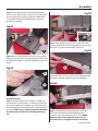
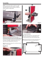
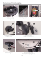
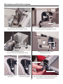
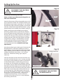
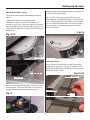
AXMINSTER
Hobby
SERIES
HBS205N 8"
Bandsaw
Code 508203
Index of Contents
Index of Contents
02
Declaration of Conformity
02
What’s Included
03-04
General Instructions for 230V Machines
05-06
Specification 06
Assembly06-07-08
Illustration and Parts Description
09-10-11-12-13
Setting Up the Saw
14-15-16-17
Operating Instructions
17-18
Changing the Saw Blade
18-19
Routine Maintenance
20
Parts Breakdown/List
21-22-23-24
Wiring Diagram
25
Bandsaw Blades
26
Notes27
Declaration of Conformity
Copied from CE Certificate
Manufactured by Qingdao D&D Electromechanical
Technologies Co., Ltd. is in compliance with the
standards determined in the following Council
Directive.
The undersigned, T. Fuhrmann
Authorised by Qingdao D&D Electromechanical
Technologies Co., Ltd. 23rd FL., D&D Fortune Center
No. 182-6 Haier Road Qingdao, Shandong 266000 P.R.
China.
EN 55014-1: 2006+1
EN 61000-3-2: 2006+A1+A2
EN 61000-3-3: 2008
EN 55014-2: 1997+A1+A2
Model Number: RBS205 (Band Saw)
2004/108/EC, 2006/42/EC
Warning
Fully read manual
and safety instructions
before use
Ear protection
should be worn
The symbols below advise that you follow
the correct safety procedures when using
this machine.
Eye protection
should be worn
2
Dust mask
should be worn
HAZARD
Motor gets hot
What’s Included
Quantity
Item Part
1 No
1 No
1 No
1 No
1 No
1 No
1 No
HBS205N 8" Bandsaw
Bandsaw Blade 1,400mm Long 6” TPI
(Mounted on the saw but not tensioned)
Table
Fence Rail with Scale
Fence Assembly
Mitre Fence
Push Stick
A
Model Number
RBS205
(Code: 508203)
B
C
D
E
F
Bag Containing:
G
H
I
J
K
L
M
4 No
M6 x 12mm Bolts
4 No
M6 Shakeproof Washers
4 No
M8x12mm Bolts
4 No
M8 Washers
1 No
Angled Bolt and Nut
1 No
3mm Hex Key
1 No
10-13mm Spanner
1 No
Instruction Manual
Having unpacked your saw (see below) and its accessories please dispose of any unwanted packaging
properly. The cardboard packaging is biodegradable.
B
A
3
What’s Included
E
F
C
D
M
J
I
L
G
K
H
4
General Instructions for 230V Machines
not use any solvents or cleaners, as these may cause
damage to any plastic parts or to the electrical
components. Keep the work area as uncluttered as is
practical, this includes personnel as well as material.
Good Working Practices/Safety
The following suggestions will enable you to observe
good working practices, keep yourself and fellow
workers safe and maintain your tools and equipment
in good working order.
Under no circumstances
should CHILDREN be allowed
in work areas.
WARNING! KEEP TOOLS AND
EQUIPMENT OUT OF THE
REACH OF YOUNG CHILDREN
It is good practice to leave the machine unplugged
until work is about to commence, also make sure
to unplug the machine when it is not in use or
unattended. Always disconnect by pulling on the
plug body and not the cable. Once you are ready to
commence work, remove all tools used in the setting
operations (if any) and place safely out of the way.
Re-connect the machine.
Primary Precautions
These machine are supplied with a moulded 13
Amp. plug and 3 core power cable. Before using the
machine inspect the cable and the plug to make
sure that neither are damaged. If any damage is
visible have the tool inspected/repaired by a suitably
qualified person. If it is necessary to replace the plug,
it is preferable to use an ‘unbreakable’ type that will
resist damage on site. Only use a 13 Amp plug and
make sure the cable clamp is tightened securely. Fuse
as required. If extension leads are to be used, carry
out the same safety checks on them and ensure that
they are correctly rated to safely supply the current
that is required for your machine.
Carry out a final “tightness” check e.g. guide fence,
table tilt, etc., check that the ‘cutting path’ (in this
case the path that the work piece will travel) is
unobstructed.
Make sure you are comfortable before you start
work; balanced, not reaching etc.
If the work you are carrying out is liable to generate
flying grit, dust or chips wear the appropriate safety
clothing, goggles, gloves, masks etc. If the work
operation appears to be excessively noisy, wear
ear-defenders. If you wear your hair in a long style,
wearing a cap, safety helmet, hair net, even a
sweatband, will minimise the possibility of your hair
being caught up in the rotating parts of the tool.
Likewise, consideration should be given to the
removal of rings and wristwatches, if these are liable
to be a ‘snag’ hazard. Consideration should also be
given to nonslip footwear, etc.
Work Place/Environment
Make sure when the machine is placed that it
sits firmly on the floor, that it does not rock and is
sufficiently clear of adjacent obstacles so that cutting
operations will not be impeded. Check you have
adequate clearance both in front of and behind the
machine when cutting long stuff. If you are liable to
be processing unwieldy or awkward work pieces, it is
suggested that you consider fastening the machine
down to the floor.
The machine is not designed for sub-aqua operation,
do not use when or where it is liable to get wet. If the
machine is set up in the open, and it starts to rain
(unusual though this would be in U.K.), cover it up or
move it into the dry. If the machine has got wet; dry
it off as soon as possible with a cloth or paper towel.
Do not use 230V a.c. powered machines anywhere
within a site area that is flooded or puddled and do
not trail extension cables across wet areas. Keep the
machines clean; it will enable you to more easily see
any damage that may have occurred. Clean the
machine with a damp soapy cloth if needs be, do
Do not work with cutting tools of any description
if you are tired, your attention is wandering or you
are being subjected to distraction. A deep cut, a lost
fingertip or worse; is not worth it!
Do not use this machine within the designated safety
areas of flammable liquid stores or in areas where
there may be volatile gases. There are very expensive,
very specialised machines for working in these areas,
THIS IS NOT ONE OF THEM.
5
General Instructions for 230V Machines
Above all, OBSERVE…. make sure you know what is
happening around you and USE YOUR COMMON
SENSE.
Check that blades are the correct type and size, are
undamaged and are kept clean and sharp, this will
maintain their operating performance and lessen the
loading on the machine.
Specification
Code508203
ModelHBS205N
RatingHobby
Power
250W (230V)
Blade Speed
274 m/min
Blade Length
1,400mm
Blade Width Min/Max
6-13mm
Max Width of Cut
200mm
Max Depth of Cut 80mm
Max Width of Cut with Fence
170mm
Table Size
300 x 300mm
Table Tilt
0° to +45°
Table Height
290mm
Wheel Diameter
200mm
Dust Extraction Outlet
40mm OD
Overall L x W x H
470 x 340 x 680mm
Weight20kg
Please read the Instruction Manual prior to using your new machine; as well as the operating procedures for
your new machine, there are numerous hints and tips to help you to use the machine safely and to maintain
its efficiency and prolong its life.
Keep this Instruction Manual readily accessible for any others who may also be required to use the
machine.
Assembly
Fig 01
Fitting the Table
NOTE: The table can be fitted without removing the
bandsaw blade. However, if you feel safer with the
bade removed, loosen the blade tensioning knob
(A),see fig 01 and very carefully remove the blade. To
refit the blade refer to pages 18-19 for “Changing the
Saw Blade”.
A
WARNING! WE ADVISE YOU
WEAR GLOVES AS THE BLADE
HAS SHARP TEETH!
6
Assembly
Step 1 Locate the bandsaw table (B), the four M6
bolts (G) and shake proof washers (H). Slot the blade
into the table’s slot and line up the threaded holes
in the table with the pre-drilled holes on the tilt
quadrant, see fig 02.
Fig 04
Fig 02
J
I
Step 2 Find the fence rail (C), line up the half moon
cutouts with the four bolts in the table and insert the
fence rail up against the table (B), see fig 05.
B
Fig 05
Step 2 Place a shake proof washer (H) over each M6
bolt (G),screw the bolts through the tilt quadrant into
the table and tighten using the supplied spanner, see
fig 03.
C
Fig 03
H
Secure the fence rail (C) in position by tightening the
four bolts with the supplied spanner, see fig 06.
Fig 06
G
Fitting the Fence
Step 1 Locate the fence rail (C), fence assembly (D),
four M8 bolts (I) and washers (J). Place a washer over
the end of each bolt and lightly screw the bolts into
the threaded holes beneath the front of the table (B),
see fig 04. NOTE: Leave sufficient distance between
the bolt head and table for mounting the fence
rail.
Step 3 Locate the fence assembly (D). Lower the
fence over the table until the clamping lever
assembly slots into the fence rail’s “T” slot. NOTE:
Make sure the clamping hook to the rear of
the fence (D) has engaged over the rear of the
7
Continues Over...
Assembly
table. Twist the locking lever clockwise to adjust
the clamping tension.(Two rotations should be
adequate) then press down the lever to lock the
fence in position, see figs 07-08.
F
Fig 07
D
Clamping lever
Fence rail “T” slot
Fig 11
Fig 08
E
Table “T” slot
Securing the Bandsaw
Step 1 Place the bandsaw on a work bench. Mark
the position of the holes in the bandsaws base,
place the bandsaw to one side and drill the holes.
Step 4 Locate the angled bolt (K), screw the
threaded end of the bolt into the threaded hole to
the top of the bandsaw frame and, using the supplied
10mm spanner, tighten with the nut to lock the bolt
in position, see fig 09. Find the push stick (F) and
hook it onto the angled bolt (K), see fig 10.
Step 2 Line up the holes and secure the bandsaw in
place with bolts, washers and shake proof nuts.
305mm
Step 5 Locate the mitre fence (E) and slide it into the
table’s “T” slot, see fig 11.
4ø
220mm
250mm
Fig 09-10
K
8
mm
8.5
335mm
Illustration and Parts Description
Blade tensioning knob
Upper wheel door
Upper door locking screw
Upper blade guide and guard
Guide fence
Blade
ON/OFF buttons
Mitre fence
Fence guide rail
Lower wheel door
Saw table ‘T’ slot for mitre fence
Lower door locking screw
9
Illustration and Parts Description
A
ON
OFF
B
Mitre fence assembly (A)
Index and pointer (B)
Table levelling stop bolt
ON/OFF NVR switch assembly
A
B
B
A
Blade guide adjusting knob (A)
Blade guide clamp (B)
Tracking control knob (A)
Tracking control butterfly lock (B)
A
C
B
Blade tensioning knob
Tilt quadrant (A), Tilt scale (B)
Tilt scale pointer and adjusting screw (C)
10
Illustration and Parts Description
Main saw frame
Tracking control
knob and lock
Upper blade guide
adjusting knob
Upper blade guide clamp
MItre fence
Table insert
Push stick
Power cable
Saw table
Tilt mechanism
Tilt mechanism clamp
Dust extraction outlet
Motor assembly
Motor air vents
11
Illustration and Parts Description
A
B
A
B
Lower blade guide assembly (A)
Blade guide pin and clamping grub screw (B)
B
Upper blade guide assembly (A)
Rear thrust bearing and clamping grub screw (B)
A
A
Lower blade guide guard (A)
Rear thrust bearing and clamping grub screw (B)
Upper guide assembly fore and aft
clamping grub screw (A)
Decrease tension
A
B
Increase tension
Blade tensioning spring (A),
under tension
Blade tensioning spring (B)
with no tension applied
12
Twist the locking lever clockwise to adjust the clamping
tension, (Two rotations should be adequate) then press
down the lever to lock the fence in position.
Illustration and Parts Description
Upper saw wheel
Upper wheel mounting
Blade guide assembly
Fence clamping lever
Saw table slot
Lower saw wheel
Saw wheel brush
Dust extraction outlet
13
Setting Up the Saw
Fig 12
DISCONNECT THE SAW FROM
THE MAINS SUPPLY!
Tensioning and tracking the blade
Blade
Make sure both top and bottom blade guides are
well clear of the blade.
Tyre
Open the front covers fully, giving good access to the
top compartment of the saw and good visibility into
the bottom compartment. (see page 13). For tracking
the blade first adjust all bearing guides so that there
well clear of the blade. Check that the blade is sitting
approximately in the middle of the wheels, see fig 12.
Fig 13
Apply some tension to the blade by turning the
tensioning wheel clockwise. Spin the top wheel by
hand, and check that the blade remains centrally on
the tyre, see fig 13. If it does not, loosen the tracking
control lock and adjust the tracking by turning the
tracking control at the rear of the upper saw wheel
compartment, see fig 14. Viewed directly onto the
tracking control wheel, turning clockwise should
cause the blade to track to the rear of the tyre,
anti-clockwise to the front (DO NOT make large
adjustments).
Spin the top wheel again, check again. Continue until
the blade tracks in the centre of the tyres with no
appreciable to and fro movement. Tension the blade
fully. A sideways push of about 7-8 lbs(3+kgs) in the
middle of the blade should allow a 1/4” (6.5mm)
distension. Check the tracking again, adjust if
necessary.
Fig 14
Tracking control lock
Connect the power to the machine. Stand clear and
start the saw, check that the saw is running smoothly,
(no thumps, bumps,knocking or excessive vibration)
and the blade appears to be tracking correctly (in
one place). You can check this by holding a marker
e.g. a pencil, close to the back of the blade (approach
from the back of the blade only) and check that the
gap remains constant. If it doesn’t, adjust the tracking
until it does. If you adjust the tracking with the saw
running, make very small adjustments and wait for
the saw to react before you adjust again, sometimes
the reaction is not instantaneous. Once you are
satisfied that the tracking is correct switch the
machine off and allow it to run to a stop. Retighten
the tracking control lock.
Tracking control
DISCONNECT THE SAW FROM
THE MAINS SUPPLY!
14
Setting Up the Saw
Checking the table is square
If the preset table stop has been fitted, proceed as
follows:Loosen the butterfly nut clamping the tilt
mechanism, see fig 15, and turn the table hard
against its stop. This is a bolt with a lock nut screwed
into the underside of the table, see fig 16, that acts as
a stop when it strikes the machine frame. Tighten the
butterfly nut.
Check that the blade is perpendicular to the table. If it
is not, try resetting the table.
If it is still not correct, loosen the locking nut and
adjust the bolt until perpendicularity is achieved, see
fig 16. Tighten the lock nut and then re-check. When
you are satisfied that the table is set correctly, check
that the pointer of the tilt gauge reads zero, if not,
adjust it, see fig 18.
Fig 18
Fig 15-16
A
B
Butterfly nut
Tilt pointer (A) and tilt gauge (B)
Setting the Fence
Always make sure the fence is parallel to the table
by placing an engineer’s rule against the fence and
setting equal distances to the front and back face of
the fence, see figs 19-20.
Fig 19-20
Back face
Locking nut
Make sure the upper blade guide is raised as high as
possible. Place a square on the table and move it up
against the blade (behind the teeth), see fig 17.
Front face
Fig 17
‘T’ slot
15
Continues Over...
Setting Up the Saw
Fig 24-25
DISCONNECT THE SAW FROM
THE MAINS SUPPLY!
Setting the Blade Guides
Lower the upper blade guide to approximately 1
1/2”(38mm) above the table by loosening the blade
guide height clamp and turning the adjusting knob.
Clamp in place, see figs 21-22. Loosen the grub screw
(A) holding the guide assembly in place, see fig 23.
Adjust the fore or aft position so that the leading
edges of the side guide pins are approximately 2mm
behind the gullets of the saw blade.
Re-tighten the grub screw, see figs 24-25.
2mm
Blade guide
Guide assembly
Fig 21-22
Guide pins
38mm
Steel rule
Fig 26
Just touching the blade
Rear thrust bearing
Adjusting knob
B
Blade guide clamp
Fig 23
A
Loosen the grub screw (B) that clamps the rear
thrust bearing and adjust the thrust bearing so it’s
just touching the blade; re-tighten the grub screw,
see fig 26. Turn the blade by hand to check the thrust
bearing turns. Loosen the two grub screws holding
the guide pins (D), move to approximately 0.5mm
from each side of the blade. Re-tighten the grub
screws. NOTE: A five pound note is approximately
0.5mm thick, slide a note between the blade and
guide pin until the pin is set to the correct thickness.
Re-tighten the grub screws (D), see fig 27. Repeat for
the other guide bush.
16
Setting Up the Saw
Fig 27
D
Close the upper and lower doors, re-connect the
power, switch the saw on, allow to run for several
minutes, check that the blade is still tracking correctly,
there is no excessive vibration, etc. Switch off and
wait until the saw comes to a complete stop. The saw
is ready to be used.
Operating Instructions
Guide pin
1. Make sure you have read and fully understood the
general instructions and safety precautions that are
printed in the preceding pages of this manual.
Setting the Lower Blade Guides
NOTE: For easier access to the lower blade guides
it is recommended you remove the table.
Open the lower wheel access door then open the
lower blade guard door, see fig 28. Repeat the
procedures as described for the upper blade guides
and thrust bearing, see fig 29. Once all adjustments
are completed rotate the blade, replace the table and
close the blade guard door.
Fig 28
Blade guard door
2. Before connecting the machine to the supply;
check the tool for obvious signs of damage, paying
particular attention to the plug and the power cable.
Rectify or have rectified any damage you discover.
Check that the blade you are using is the correct one
for the job in hand. Change the blade if necessary.
Check the blade is not damaged; is clean, sharp,
tracks properly and is correctly tensioned.
3. Set the upper blade guide to approximately 12mm
(1/2”) above the height of the work piece.
4. Check, especially on site, that there are no foreign
objects e.g. old nails, screws, small stones etc.
embedded in the material you are about to cut.
5. Check that all accessories, tools etc., that have been
used to set the machine up, are removed and set
carefully aside or stowed away correctly.
6. Ensure the machine is switched off. Plug the power
cable into a correctly rated switched socket outlet.
If extension leads are being used, check these for
damage, do not use if damaged; if you are working
outside, check that any extension cables in use are
rated for outside work. Switch on. Allow the saw to
run up to speed.
Lower guide pins
Fig 29
7. Make sure that the material you are about to cut
is within the machine capacity, and the cut you are
about to make is within the blades’ capabilities. e.g.
Do not try to cut a 1” radius curve using a 5/8” blade.
8. Make sure the blade is not in contact with the
material when you start the saw. Start the cutting operation.
Lower thrust bearing
17
Continues Over...
Operating Instructions
Do not try to cut too quickly; the correct cutting
speed, if one could be so precise, would never see
the blade pushed back against the thrust bearing
The saw would cut and clear the saw line at the rate
the work piece was fed into it. If you notice that you
require more and more pressure to effect the cut,
and the blade is in continual contact with the thrust
bearing, the chances are the blade is becoming blunt.
Check and change if necessary.
Do not let go of the work piece; if you have to change
your grip, make sure one hand is holding the material
at all times.
9. If you are cutting long pieces of material think
about sawing cutouts (i.e. a saw cut from the edge
of the material to the saw line) along the saw line
so that you can discard the off cuts as you progress
down the saw line.
12. Remember to check the blade tension after a
new blade has been ‘working’ for 30-60 mins. The
blade will ‘stretch’ slightly when new.
13. Do not release the tension on the saw blade
when work is complete. The blades and the main
saw frame do not respond kindly to frequent large
changes in stress and tension. Only release the
tension to change the blade or if the blade is to be
removed because the machine is to be ‘mothballed’
for a lengthy time period. The blade in tension over
a long period of non-use will cause the tyres to
develop ‘flat’ spots. Open the saw cut, either by
pulling apart or driving a wedge in close to the back
of the blade. Try to “wriggle” the blade free of the saw.
If this is not possible; check that the saw is free in the
cut, start the saw, allow it to run up to speed and ‘cut
out’ as quickly as possible. The removal of the ‘off
cut’ may well prevent the saw jamming again if you
resume the original cut.
10. Observe the old woodworkers’ adage of never
allowing your hand/fingers within one handbreadth
of the blade.
WARNING! IF THE SAW JAMS!
Switch off immediately.
11. If you have to cut very small pieces of material,
arrange or manufacture some form of ‘shoe’ to carry
the timber. If the work piece is exceptionally small,
find something to use as a sacrificial carrier and
mount the work piece on it with double sided tape,
or similar.
Changing the Saw Blade
Fig 30
DISCONNECT THE SAW
FROM THE MAINS SUPPLY!
Put the table back to the level position if it has been
tilted. Set the upper blade guide assembly
approximately midway in the throat. Open the top
and bottom covering doors. Remove the fence and
guide rail and place safely aside. Slacken the blade
tension by turning the blade tensioning wheel
anti-clockwise, until the blade can be easily slipped
off the wheels, see fig 30.
Remove the blade carefully, “wriggling” it clear of the
upper blade guard, and out through the slot in the
table. NOW is an excellent time to clean out the
interior of the machine, remove the impacted ‘crud’
from the tyres, apply a little light oil to the screw
Slacken the blade by turning the
tensioning wheel anti-clockwise
threads of the blade tensioner, and the tracking
control. The pivots and the slides of the top wheel
18
Changing the Saw Blade
mounting assembly could likewise be lightly oiled.
If you are fitting a new blade it will have been
supplied to you “folded”, bound together in this
configuration with tape or tie wrap. Also check the
blade did not “unfold” inside out. i.e. looking at the
right side front of the loop, the teeth should be on
the front of the blade, and pointing down. If you
can’t arrive at this view, turn the blade inside out
from its current position and look again.
lower blade guides, see fig 31. Apply some tension
to the blade. Turn the top wheel by hand to ensure
the blade will not skip off the wheels and the blade is
travelling in the blade guides, see fig 32. Apply a little
more tension and check by once again spinning the
Fig 32
Note: Be very cautious when
you “unfold” the blade; it
tends to ‘spring’ open, blade
and teeth going everywhere.
MAKE SURE THE BLADE
TEETH ARE POINTING DOWN!
Open up all blade guide pins so that they are clear
of the blade. Hold the blade approximately midway
on either side of the loop and feed into the table slot.
When you get to the table insert cutout void, work
the left side of the loop into the slot in the guard in
the neck of the main saw frame. “Wriggle” the right
hand side of the blade through the guard on the
upper blade guide assembly. Ease the blade over the
wheels and locate the blade in both the upper and
upper saw wheel by hand. Loosen the upper blade
guide clamp and set the upper blade guide assembly
so that the top of the blade guide is level with the
centre of the top drive wheel, see fig 33. Re-tighten
the clamp.
Fig 33
Fig 31
Top drive wheel
Blade guide
When you are sure that the blade is “ON” and stable,
re-fit the fence rail and fence. Now carry out the
procedures as detailed in “Setting up the Saw”.
19
Routine Maintenance
Daily
Monthly
• Keep the machine clean.
• Check the saw blade for missing teeth and
cracks, see fig 34.
• Spray oil the bare metal surfaces.
• Open the lower and upper doors and check the
condition of the tyres & the drive belt, see fig 34.
Weekly
• The pivots and the slides of the top wheel mounting
assembly and the captive stub axle of the belt
tensioner in its slot could likewise be lightly oiled.
• Using an air line (wearing goggles) blow out the
vents in the motor casing, see fig 35.
• Open the top & bottom wheel covers and clean out
all saw dust.
Clean out impacted ‘crud’ & saw dust
• Clean impacted ‘crud’ from the tyres, apply a little
oil to the screw threads of the blade and drive belt
tensioners. DO NOT USE OIL near the belt.
Fig 34
a
b
Fig 35
c
Clean out impacted ‘crud’ & saw dust
• Check for missing teeth (a)
• Check the condition of the tyres (b)
• Blow out motor vents (c)
20
Oil
Parts Breakdown/List
21
Parts Breakdown/List
ITEM
PART NO.
NAME
Q’ty
1
DJ200020200
Rip fence assembly
1
2
DJ200020103A
Support
3
3
31503009A
Locking knob
1
4
DJ200020101D
Working table
3
5
DJ25002005
Table insert
1
6
DJ200020112
Rip fence carrier extrusion
5
7
GB/T14 M6×16
Screw
1
8
31502015
Knob
1
9
GB/T14 M6×16
Screw
2
10
DJ25002006A
Guide piece
1
11
DJ250A02003
Table trunnion upper
6
12
GB/T862.2 6
Dental pad
4
13
DJ200030501
Locking pin
1
14
DJ250A03021
Thrust bearing shaft
2
15
DJ250A03022A
Housing upper guide
1
16
GB80-85 M6×6
Hex socket set screw
4
17
DJ200030502B
Upper pilot pin
2
18
GB/T276-94 625-2Z
Bearing
2
19
GB80-85 M6×8
Hex socket set screw
2
20
GB80-85 M6×12
Hex socket set screw
1
21
GB845-85 ST3.5×9.5
Cross recessed pan head tapping screw
4
22
DJ200030409
Seat upper guide
1
23
DJ200030401
Guide lever
1
24
GB14-88 M6×60
Cup head square neck bolt
1
25
DJ200030402
Shaft
1
26
DJ200040311
Cover board
1
27
DJ200030410
Slide board
1
28
DJ200030602B
Lower pilot pin
2
29
DJ200030601
Housing lower guide
1
30
DJ200030404
Rack
1
31
GB5783-86 M6×12
Hex Bolt
8
32
GB93-87 6
Spring washer
4
33
DJ200030102
Bandsaw tyre
2
34
DJ200030201
Lower wheel
1
22
Parts Breakdown/List
ITEM
PART NO.
NAME
Q’ty
35
DJ200030801
Saw blade
1
36
GB5783-86 M6×12
Hex Bolt
8
37
31503030
Tongue
2
38
31503033
Housing with nut
2
39
DJ200010301G
Door lower
1
40
31503020
Washer
2
41
31503032
Tongue housing
2
42
31503031
Slotted insert
2
43
GB97.1-85 4
Washer
4
44
GB818-85 M4×6
Cross recessed pan head screw
7
45
DJ200010201H
Door upper
1
46
GB894.1-86 10
Circlip for shaft
1
47
DJ200030101
Upper wheel
1
48
GB14-88 M8×65
Cup head square neck bolt
1
49
31504015
Brush
1
50
DJ200030701
Spacer bushing
1
51
CK-1A
Switch
1
52
GB819-85 M4×12
Cross Pan Hd Screw
2
53
DJ25005004B
Switch plate
1
54
DJ200030301
Bearing bolt upper
1
55
GB896-86 6
Bearing gasket
2
56
DJ250A03003A
Bearing bolt support upper
1
57
GB6177-86 M6
Hex Flanged nut
4
58
DJ250A03010
Blade tensioner
1
59
DJ200030900
Guide plate assembly
1
60
DJ250A03007
Pin guide
1
61
DJ200030403A
Guide piece
1
62
GB5783-86 M6×40
Hex Bolt
1
63
GB6177-86 M8
Hex Flanged nut
1
64
GB14-88 M6×16
Cup head square neck bolt
2
65
DJ25004011
Lower blade guard
1
66
GB889-86 M6
Hex Locking nut
2
67
GB5783-86 M6×20
Hex Bolt
5
68
YYG71L4W-01 B14
Motor
1
23
Parts Breakdown/List
ITEM
PART NO.
NAME
Q’ty
69
DJ200020108
Plank
1
70
DJ200020102
Locking handle
1
71
DJ200030406
Locking knob
1
72
DJ250A05005
Power cord and plug
1
73
DJ200030405
Setting knob
1
74
DJ200030407
Spring
1
75
DJ200030408
Dishing cover
1
76
GB97.1-85 6
Washer
4
77
DJ250A03008
Setting knob
2
78
GB5783-86 M8×45
Hex Bolt
1
79
31503007
Wing knob
1
80
GB/T1792 A16
Butterfly spring
9
81
DJ250A03011
Shaft
1
82
DJ200030302
Thread bolt
1
83
DJ200010401
Tamello plug
1
84
DJ200010100
Frame
1
85
DJ250A03009
Nut
1
86
GB862.2-87 6
Serrated lock washer
2
24
Wiring Diagram
25
Bandsaw Blades
Standard Axcaliber Bandsaw Blades
1,400mm(55”) x 0.014”
Axminster HBS310N Bandsaw
TPIWidth
61/4"
101/4"
141/4”
241/4”
321/4”
43/8"
63/8”
103/8”
143/8”
61/2"
Code
508253
508254
508255
508256
508257
508258
508209
508260
508261
508262
26
Notes
27
The Axminster guarantee is available on
Hobby, Trade, Industrial, Engineer, Air Tool & Axcnc Technology Series machines
It’s probably the most comprehensive FREE guarantee ever- buy with confidence from Axminster!
So sure are we of the quality, we cover all parts and labour free of charge for three years!
• Look for the icon and put your trust in Axminster
• No registration necessary - just keep your proof of purchase
• Optional Service Plan for Industrial Series machinery
Great value & easy-to-use,
perfect for use at home
Solid, reliable machines
designed for daily use
Top performers with class leading features and
build quality for use in busy workshops
Quality, precision machines
for the workshop or education
Small machines for the home
engineer
Compressors and tools for home or
workshop use; durable and great value
Free Three Year Guarantee on Axminster Hobby, Trade and Industrial Series
woodworking and engineering machines, Axminster Air compressors and Air
Tools, and bench top grinders - no registration necessary just proof of purchase.
We will repair or replace at our discretion and will collect only from a UK
mainland address, irrespective of the original delivery address.
The Guarantee assumes that you have bought the correct machine for the
required operation, in accordance with our guidelines; have operated and
maintained it in accordance with the instruction manual; and that all cutting
machines will be used with a blade which is sharp and serviceable at all times.
It does not cover consumable items purchased with the original product,
including original blades or abrasives.
Precision CNC machines for
industry and education
Normal wear and tear, misuse, abuse and neglect are excluded and the machine
should not have been modified in any way. Please do not attempt to service the
product without first contacting us; we are happy to guide you but failure to do
so may invalidate the guarantee.
The Guarantee is transferable from owner to owner in the first three years but
you must have original proof of purchase. Should we need to replace a machine
in the first three years the guarantee will still continue to be effective from the
original purchase date.
Full Terms and Conditions can be found at axminster.co.uk/terms
This guarantee does not affect your statutory rights.
For more information visit axminster.co.uk/3years
Please dispose of packaging for the product in a responsible manner. It is suitable for recycling.
Help to protect the environment, take the packaging to the local recycling centre and place into
the appropriate recycling bin.
Only for EU countries
Do not dispose of electric tools together with household waste material. In observance of
European Directive 2002/96/EC on waste electrical and electronic equipment and its
implementation in accordance with national law, electric tools that have reached the end of their
life must be collected separately and returned to an environmentally compatible recycling facility.
Axminster Tools & Machinery Ltd
Weycroft Avenue, Axminster, Devon EX13 5PH
axminster.co.uk