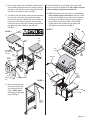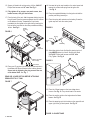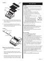
1
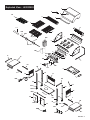
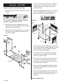
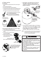
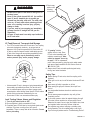
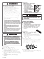
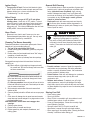
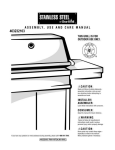
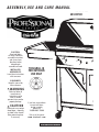
ASSEMBLY,USE AND CARE MANUAL
4632235
463233503
CAUTION:
Read and follow
all safety statements,
assembly instructions,
and use and care
directions before
attempting to
assemble and cook.
INSTALLER/
ASSEMBLER:
Leave these instructions
with consumer.
THIS GRILL IS
FOR OUTDOOR
USE ONLY
CONSUMER:
Keep this manual for
future reference.
WARNING
Failure to follow all
manufacturer’s
instructions could
result in serious
personal injury and/or
property damage.
CAUTION
Some parts may contain
sharp edges - especially
as noted in the manual!
Wear protective gloves
if necessary.
®
If you have any questions
or need assistance
during assembly,
please call
1-800-241-7548.
Visit us on the web at:
www.charbroil.com
463233503 / P8012066A (06-18-03)
463233503 • 1
WARNING
FOR YOUR SAFETY
1. Do not store or use gasoline or other
flammable vapors and liquids in the
vicinity of this or any other appliance.
2. An LP Tank not connected for use
shall not be stored in the vicinity of
this or any other appliance.
FOR YOUR SAFETY
If you smell gas:
1. Shut off gas to the appliance.
2. Extinguish any open flame.
3. Open lid.
4. If odor continues, immediately call
your gas supplier or your fire
department.
Call Grill Service Center For Help And Parts
• If you need help or warranty parts call !1-800-241-7548, or
send a FAX to 1-706-576-6355.
Business hours: Open 24 hours - Seven days a week.
• To order non-warranty replacement parts or accessories (grill
cover, cleaners, paint) call 1-800-993-2677 or send a FAX to
1-706-565-2121.
Important: Fill out Warranty Information below
Warranty Information
Model Number _______________________________
Installation Safety Precautions
• Use grill only with LP (propane) gas and the regulator/valve
assembly supplied.
• Grill installation must conform with local codes, or in their
absence with National Fuel Gas Code, NFPA 54 / ANSI
Z223.1. Handling and storage of LP cylinders must
conform to LP Gas Code NFPA/ANSI 58. Grill is not for
use in or on recreational vehicles and/or boats.
• All electrical accessories (such as rotisserie) must be
electrically grounded in accordance with local codes, or
National Electrical Code, ANSI / NFPA 70. Keep any
electrical cords and/or fuel supply hoses away from any
hot surfaces.
• This grill is safety certified for use in the United States only.
Do not modify for use in any other location. Modification
will result in a safety hazard.
Safety Symbols
• The symbols and boxes shown below explain what each
heading means. Read and follow all of the messages found
throughout the manual.
D ANGER
• DANGER: Indicates an imminently hazardous
situation which, if not avoided, will result in death or
serious injury.
WARNING
• WARNING: Be alert to the possibility of serious
bodily injury if the instructions are not followed. Be
sure to read and carefully follow all of the messages.
Lot Number (on carton label) _____________________
Serial Number _______________________________
Date Purchased ______________________________
CA
UTION
CAUTION
• For residential use only. Do not use for commercial
cooking.
2 • 463233503
CA
UTION
CAUTION
• CAUTION: Indicates a potentially hazardous
situation which, if not avoided, may result in minor
or moderate injury.
Table of Contents
For Your Safety ......................................................................... 2
Call Grill Service Center For Help And Parts ........................... 2
Installation Safety Precautions ................................................. 2
Safety Symbols ......................................................................... 2
Table of Contents ..................................................................... 3
Warranty .................................................................................... 3
Before Beginning Assembly ..................................................... 4
Parts List ................................................................................... 4
Exploded View .......................................................................... 5
Assembly ................................................................................ 6-9
Use and Care ........................................................................ 9-14
Storing Your Grill ..................................................................... 13
Indirect Cooking ...................................................................... 14
Food Safety .............................................................................. 14
Troubleshooting .................................................................. 15-16
Warranty
Char-Broil warrants to the original consumer-purchaser that
this product shall be free from defects in workmanship and
materials under normal and reasonable use and correct
assembly (if assembled by consumer-purchaser), from date of
purchase.
Stainless steel and die cast parts - 99 years
Electronic ignition and burners - 10 years
Remaining parts - 2 years
Char-Broil will, at its option, refinish or replace any
product or part found to be defective during the warranty
period. Char-Broil will require you to return the part(s)
claimed to be defective, for its inspection, freight or postage
prepaid.
If you wish to obtain performance of any obligation under this
limited warranty, you should write to:
CHAR-BROIL
Consumer Warranty / P.O. Box 1240
Columbus, GA 31902-1240
Char-Broil may require reasonable proof of purchase and
we suggest you keep your receipt. In the state of California only,
if refinishing or replacement of the product is not commercially
practicable, the retailer selling this product or Char-Broil will
refund the purchase price paid for the product, less the amount
directly attributable to use by the original consumer-purchaser
prior to discovery of the nonconformity. In addition, in the state of
California only, you may take the product to the retail
establishment from which it was purchased or to any retail
establishment selling this product in order to obtain performance
under this warranty.
This warranty does not include the cost on any
inconvenience or property damage due to failure of the product
and does not cover damage due to misuse, abuse, accident,
damage arising out of transportation of the product, or damage
incurred through commercial use of the product. This express
warranty is the sole warranty given by the manufacturer and is in
lieu of all other warranties, express or implied, including implied
warranty of merchantability or fitness for a particular purpose.
Neither Char-Broil dealers nor the retail establishment selling this
product has any authority to make any warranties or to promise
remedies in addition to or inconsistent with those stated above.
Char-Broil's maximum liability, in any event, shall not exceed the
purchase price of the product paid by the original consumerpurchaser. Some states do not allow the exclusion or limitation of
incidental or consequential damages. So the above limitations or
exclusions may not apply to you. This warranty gives you specific
legal rights and may also have other rights which vary from state
to state.
463233503 • 3
Before Beginning Assembly
• Necessary tools for assembly of your grill include:
Phillips® screwdriver, pliers and adjustable wrench.
Certified Grill Parts And Accessories®, Char-Broil and Design®, Char-Broil (Gas Grill Briquettes)®,
Char-Diamonds®, Cooking Zone and Design®, Diamond Flame®, Executive Chef®, Faststart®,
Flare Fighter®, FlavorMaster®, Gas Grill Silouette and Design®, H2O Smoker®, Lava Flame®,
MasterFlame®, MasterFlame Precision Cooking System®, PowerSpark®, Quantum®, VIP®,
PrecisionFlame and Design®, Sierra®, and TruFlame® are registered Trademarks of the W.C. Bradley
Company. Thermos® is a registered trademark of the Thermos Company and its affiliates.
Artisan Collection by Char-Broil ™, C3 and Design™, Char-Broil and Design™, Flame Design™,
FlavorTents™, Grill 2 Go™, Grillin’ Stick™, Keeper of the Flame™, Keepers of the Flame™,
Natural Grip™, Outdoor Cooking Collection and Design™, Patio Bistro™, PrecisionFlame™, Pro-Check™,
QuickSet Grills and Design™, SmokerTents™, The Big Easy™, The Minute Grill™, The Edge™,
The Tuscan Collection™, and The Urban Grill™ are Trademarks of the W.C. Bradley Company. Universal
Grill Parts and Design™ is a trademark of the Thermos Company and its affiliates.
Protected under one or more of the following U.S. Patents: 4,598,692; 4,624,240; 4,747,391; 4,747,391;
4,817,583; 4,924,846; 4,989,579; 5,003,960; 5,076,256; 5,076,257; 5,090,398; 5,109,834; 5,224,676;
5,277,106; 5,421,319; 5,441,226; 5,452,707; 5,458,309; 5,566,606; 5,566,606; 5,579,755; 5,582,094;
5,613,486; 5,649,475; 5,706,797; 5,711,663; 5,765,543; 5,931,149; 5,996,573; 6,095,132; 6,135,104;
6,279,566; D282,619; D339,714; D341,292; D343,337; D358,059; D361,466; D364,535; D372,637;
D373,701; D377,735; D383,035; D397,910; D405,643; D405,643; D406,005; D406,009; D413,043; D413,229;
D413,229; D414,982; D415,388; D416,164; D416,441; D416,441; D417,587; D422,516; D423,274; D423,876;
D428,303; D435,396; D436,004; D438,059; D438,060; D438,427; D439,110; D442,505; D443,179; D443,354;
D447,384; D447,385; D447,909; D448,610; D448,614; D448,615; D448,616; D448,975; and D449,492.
Other Patents Pending.
4 • 463233503
Parts List - 463233503
Key
A
B
C
D
E
F
G
H
I
J
K
L
M
N
O
P
Q
R
S
T
U
V
W
X
Y
Z
AA
BB
CC
DD
EE
FF
GG
HH
II
JJ
KK
LL
MM
NN
OO
PP
QQ
RR
SS
TT
UU
VV
WW
XX
YY
ZZ
AAA
BBB
CCC
DDD
EEE
FFF
GGG
HHH
III
JJJ
KKK
LLL
MMM
Qty
1
1
1
1
1
2
3
3
1
3
1
1
1
1
1
1
1
1
1
1
1
3
1
1
1
1
1
3
1
4
1
1
1
2
2
1
1
2
1
2
1
1
1
1
2
1
1
1
1
2
1
4
4
1
1
1
1
2
1
1
1
1
1
1
1
1
1
1
Description
Lid
Heat Indicator
Curved Stainless Steel Handle
Name Plate - Professional Series
Warming Rack
Cooking Grid - Stainless Steel
Flame Tamer
Burner
Burner Bracket
Gas Collector Box with Electrode
Electric Wire Set
Electric Ignitor (4 port)
Back Burner
Back Burner Frame
Bowl Side Panel, Left
Bowl Side Panel, Right
Bowl Front Panel
Bowl Rear Panel
Grease Draining Tray
Grease Receptacle
Gas Manifold
Gas Valve for Main Burner
Gas Valve for Back Burner
Spark Electrode
Gas Tube
Heat Shield for Control Panel
Control Panel
Control Knob (Main Burner)
Control Knob (Back Burner)
Control Knob Seat
Griddle
Side Shelf, Left
Side Shelf, Right
Bracket for Side Shelf, LR/RF
Bracket for Side Shelf, LF/RR
Shelf Trim Plate, Right
Shelf trim Plate, Left
Side Shelf Handle
Bottom Shelf
Bowl Support Bracket
Side Cart Leg, LF
Side Cart Leg, LR
Side Cart Leg, RF
Side Cart Leg, RR
Cart Side Panel
Cart Rear Panel
Front Door, Left
Front Door, Right
Door Bracket
Door Curved Handle
Door Stop
Caster Seat
"3" Industry Caster
Regulator with Hose (27")
AA Battery
Motor
Motor Bracket
Fork
Collar
Bushing
Handle
Spit
Tool Hooks
Match Lighting Stick with Chain
Retention Screw for Tank
Caster Wrench
Hardware Pack
Owners Manual
New Part #
P00119096A
P00601181A
P00205015B
P00414034G
P01505007B
P01602005B
P01705005E
P02001031E
P02203055A
P02609002B
P02615033A
P02502024C
P02007027D
P03305006H
P00720033C
P00721033C
P00724046C
P00725044A
P02705364A
P02701041A
P05004072B
P03222024B
P03222095B
P02610005B
P03701003A
P03007051B
P02907121A
P03419031B
P03411142H
P03413011A
P05702002E
P01102009B
P01107010B
P01213005A
P01211005A
P07502001A
P07503001A
P00205016B
P01008005C
P01303002B
P00917005B
P00918005B
P00912005B
P00920005B
P07601001A
P07701002A
P04302003A
P04303003A
P03302001C
P00211004B
P05510009E
P04507003A
P05106003D
P03601004A
P05301001A
P07101002B
P05508005A
P05508006A
P05508007A
P05508008A
P05508004E
P05508011A
P05514013A
P05507031E
P06222019B
P05515002C
P06004045A
P80112066A
Exploded View - 463233503
A
D
B
EE
E
C
F
III
N
HHH
X
F
GGG
R
G
DDD
JJJ
J
Q
K
EEE
K
V
AA
Z
K
V
V
DD
FF
HH
NN
Y
DD
BB
CC
CCC
L
P
U
W
BB
BB
S
KK
II
H
J
FFF
LL
H
J
O
M
I
H
PP
SS
TT
T
BBB
NN
OO
ZZ
AAA
LLL
ZZ
RR
AAA
SS
WW
YY
UU
MM
ZZ
QQ
XX
VV
II
GG
ZZ
AAA
AAA
HH
MMM
JJ
KKK
LL
463233503 • 5
4. Screw the 4 casters into the caster seats in the bottom of
each cart leg. Turn the threaded caster stem by hand,
clockwise until it stops. Fully tighten with the wrench
provided. See Fig. 2.
Assembly - 463233503
• Unpack and remove all protective packaging.
1. Position bottom shelf with the tank hole toward the left side.
See Fig. 1.
VERY IMPORTANT: The labels on the cart legs
indicate their assembly position to the bottom shelf. LF
LF=Left
Front, LR
LR=Left Rear, RF
RF=Right Front, and RR
RR=Right
Rear. Labels should face inward toward each other when
correctly assembled. Remaining components cannot be
assembled if leg positions are incorrect.
5. Install the two side panels and one rear panel to the cart by
using 4 of the 3/16x1/2" Phillips-head screws on each
panel. Leave rear panel screws loose. See Fig. 2.
FIGURE 2
Rear
panel
Side
panel
2. Install the four cart legs to the indicated corners of the
bottom shelf using 8 of the 1/4x2-1/2" Phillips-head screws
provided. Do not fully tighten screws.
3. Install bowl support brackets, facing inward, to cart legs on
both sides using 8 of the 1/4x1/2" Phillips-head screws.
Fully tighten. See Fig. 1.
FIGURE 1
Caster
Bowl
Support
Bracket
Side
panel
6. Attach the door bracket to the lower holes in the front legs
with the end tabs pointing upward and the flange to the rear,
pointing downward. Use 2 of the 1/4x1/2" Phillips-head
screws. Do not fully tighten. See Fig. 3.
LR
Bottom
Shelf
LF
7. Attach the door stop to the bottom shelf, with the flange
facing the front , using 2 of the 3/16x3/8" Phillips head
screws. Fully tighten. See Fig. 3.
RR
Tank Hole
RF
8. Place doors into the hinge holes of the bottom shelf and
door bracket. Push door bracket down until doors are
secure and can open and close freely. Do not fully tighten
door bracket screws. See Fig. 3.
9. Remove protective film from doors. Install door handles to
doors using 4 of the 3/16x3/8" Phillips-head screws and
washers. See Fig. 3.
10. Attach the 4 side shelf brackets to the tops of the cart legs
using 8 of the 1/4x1/2" Phillips-head screws. Be sure the
flat side of each bracket faces outward. Fully tighten.
See Fig. 3.
FIGURE 3 ON NEXT PAGE
6 • 463233503
11. Place the side shelves over the brackets and cross braces
with the wider-spaced shelf holes to the outside (shelf with
trim plate on right side). Be sure the inside shelf holes align
with holes in bowl support bracket. See Fig. 3.
12. To install the side shelf handle, remove the bolt and washer
from one side of the handle (cap remains with handle).
From beneath shelf, place washer onto bolt and insert bolt
through end of shelf bracket, side shelf, and into handle.
Leave bolt loose until other side of handle is attached, then
fully tighten both sides. Repeat for other side shelf.
See Fig. 3.
FIGURE 3
14. HINT: Slide grill head into cart from the front. Use care to
avoid scratching tops of side shelves. Align the 2 holes
beneath the hang ledge on each side of the grill head with
the 2 holes in the side shelf and bowl support bracket on
the cart. Raise the grill lid and insert 4 of the 1/4x1/2"
Phillips-head screws. Beneath the side shelves, add
1/4" nuts. Do not fully tighten. See Fig. 5.
FIGURE 5
Shelf
handle
Align
holes
Side
shelf
Grill
head
Shelf bracket,
flat side facing
outward
Lower
hole
Door
bracket
Hang
ledge
Gas hose
Door
stop
Door
Hang
ledges
rest on
shelves
Hinge
hole
Handle
Remove
film
To reduce the weight of the grill head, open the grill lid and
remove the packed components. This step requires 2 people
to lift and position the grill head onto the cart.
Hinge
Screw & washer
FIGURE 4
13. Attach match lighting stick
and chain to the right rear
leg, below shelf bracket,
using one M4 X 10mm,
self-tapping, Phillips-head
screw. See Fig. 4.
Match
lighting
stick
463233503 • 7
15. Secure grill head to all cart legs using 4 of the 1/4x2-1/2"
Phillips-head screws and 1/4" nuts. See Fig. 6.
16. Fully tighten all leg screws, rear panel screws, door
bracket screws, and grill head screws.
17. From the back of the cart, slide the grease draining tray into
the grill head. Place the grease receptacle into the notches
on the bottom of the tray. Assemble the 3 tool hooks
provided to the front panel on the right shelf by inserting the
thin end of the hook first into the holes provided and sliding
all thru. See Fig. 6.
Grease
19. Unscrew the ignitor cap located on the control panel and
remove the contact and spring from the ignitor slot.
See Fig. 8.
20. Place the supplied AA battery into the ignitor slot with the
positive pole facing toward you.
21. Place the spring with contact over the battery. Screw the
ignitor cap back onto the control panel.
FIGURE 8
draining
tray
FIGURE 6
Spring
Contact
Ignitor
cap
–
+
AA Battery
Grease
receptacle
22. Attach trim plate to front of left shelf by placing top lip of
plate ABOVE bottom lip of shelf. Secure using three
3/16"x3/8" Phillips-head screws and 3/16" nuts.
Fully Tighten. See Fig. 9.
Attach grill head
to all 4 legs
FIGURE 9
Tool Hooks
18. Place your LP gas tank (not included) into the tank hole in
the bottom shelf. Be sure the tank valve is facing forward.
Secure tank by tightening the wing screw at the rear
of the bottom shelf. See. Fig. 7.
READ USE & CARE SECTION BEFORE ATTACHING
REGULATOR TO LP TANK.
Plate lip
Shelf
lip
FIGURE 7
23. Place the 3 flame tamers on the lower ledge above
burners. See Fig. 10. They should meet in the center.
24. Place the cooking grids on the ledge above the flame
tamers. See Fig. 10.
25. Place the warming rack into the slots on the upper left and
upper right of the grill bowl panels. See Fig. 10.
LP gas
tank
FIGURE 10 ON NEXT PAGE
8 • 463233503
Warming
rack
FIGURE 10
Use and Care
LP Tank
Flame tamer
Cooking
grid
Lower
ledge
26. Attach rotisserie motor bracket to bowl side panel using
screws, washers, and nuts provided, then slide motor onto
bracket. See Fig. 11.
27. Twist handle onto threaded end of spit rod, then add
bushing, collar, and forks to spit. Insert spit into motor and
rest collar in groove of opposite side.
FIGURE 11
Handle
Bushing and collar
Forks
• The LP tank used with your grill must meet the following
requirements:
• Purchase LP tanks only with these required measurements:
12" (30.5cm) (diameter) x 18" (45.7 cm) (tall) with 20 lb. (9
kg.) capacity maximum.
• Be constructed and marked in accordance with
specifications for LP tank of the U.S. Department of
Transportation (DOT). See LP tank collar for marking.
• LP tank valve must have:
• Type 1 outlet compatible with regulator or grill.
• Safety relief valve.
• UL listed Overfill Protection Device (OPD).
This OPD safety feature is identified by a
unique triangular hand wheel. Use only
OPD Hand Wheel
tanks equipped with this type of valve.
• Supply system must be arranged for vapor withdrawal and
include collar to protect LP tank valve.
LP (Liquefied Petroleum Gas)
• Is nontoxic, odorless and colorless when produced. For Your
Safety, LP gas has been given an odor (similar to rotten
cabbage) so that it can be smelled.
• LP gas is highly flammable and may ignite unexpectedly
when mixed with air.
LP Tank Filling
Spit rod
Motor
Bracket
Before Your First Cookout
•
Perform the leak test as indicated in the use and care
section.
•
Wash the cooking grids, griddle, cooking rack, and all
stainless steel surfaces with warm, soapy water. Rinse and
dry thoroughly.
•
Light burners. Check to make sure they are lit, then close
the lid and warm the grill on HI for 15 minutes. Curing of
paint and parts will produce an odor only on first lighting.
• Use only licensed and experienced dealers.
• LP tank must be purged before filling.
• Dealer should NEVER fill LP tank more than 80% of LP tank
volume. Volume of propane in tank will vary by temperature.
• A frosty regulator indicates gas overfill. Immediately close LP
tank valve and call local LP gas dealer for assistance.
• Do not release liquid propane (LP) gas into the atmosphere.
This is a hazardous practice.
• To remove gas from LP tank, contact an LP dealer or call a
local fire department for assistance. Check the telephone
directory under “Gas companies” for nearest certified LP
dealers.
• LP tank Exchange: You may choose to replace your empty LP
tank through an exchange service. Use only those reputable
exchange companies that inspect, precision fill, test and
certify their cylinders. Exchange for OPD safety feature
equipped tank as described in LP Tank
• Always keep LP tank in upright position during use, transit or
storage.
• Leak test LP tank BEFORE connecting to grill.
463233503 • 9
LP Tank Leak Test
For your safety
• Leak test must be repeated each time LP tank is exchanged or
refilled.
• Do not smoke during leak test.
• Do not use an open flame to check for gas leaks.
• Grill must be leak checked outdoors in well-ventilated area, away
from ignition sources such as gas fired or electrical appliances.
During leak test, keep grill away from open flames or sparks.
Use a clean paint brush and 50/50 soap and water
solution. Use mild soap and water.
▲ Do not use household cleaning agents.
Damage to gas train components can result.
Brush soapy solution
onto the shaded areas.
If
"growing"
bubbles appear
do not use or move
the LP tank. Contact
an LP gas supplier or
your fire department!
Connecting The Regulator To The LP Tank
1. LP tank must be properly secured onto grill.
2. Turn all control knobs including sideburner (if featured) to the OFF
position.
3. Turn LP tank OFF by turning hand-wheel
Clo
clockwise to a full stop.
O f f ckwise
4. Remove the protective cap from
LP tank valve. Always use cap and
OPD Hand
Wheel
strap supplied with valve.
Safety Relief Valve
Type 1 outlet with thread on outside
Strap and Cap
A
10 • 463233503
Use of this POL transport plug
(A) (plastic part with external
threads) will defeat safety
feature of valve.
5. Hold regulator, insert nipple (B) into LP tank valve.
Hand tighten coupling nut, holding regulator in a
straight line (C) with LP tank valve so as not to cross
thread the connection.
B
Nipple has to be
centered into the
LP tank valve
C
Hold coupling nut
and regulator as
shown for proper
connection to LP
tank valve.
6. Turn the coupling nut clockwise to tighten to a full solid stop.
The regulator will seal on the back-check feature in LP tank
valve, resulting in some resistance. An additional one-half
to three quarters turn is required to complete
connection. Tighten by hand only - do not use tools.
NOTE: If you cannot complete connection, disconnect regulator and
repeat steps 5 and 6. If you are still unable to complete the
connection, do not use this regulator!
WARNING
• Do not insert any foreign objects into the valve
outlet. You may damage the valve and cause a leak.
Leaking propane may result in explosion, fire, severe
personal injury, or death.
• Never attempt to attach this grill to the self-contained
LP gas system of a camper trailer or motor home.
• Do not use grill until leak checked.
• If leak is detected at any time, STOP and call the Fire
Department.
• If you cannot stop a gas leak, immediately close LP
tank valve and call LP gas supplier or your fire
department!
D ANGER
• NEVER store a spare LP tank under or near grill or in
enclosed areas.
• Never fill the cylinder beyond 80% full. An overfilled
spare LP tank is hazardous due to possible gas
released from the safety relief valve. The safety relief
valve on a LP tank could activate releasing gas and
cause a fire, resulting in serious injury, property
damage or death.
• If you see, smell or hear escaping gas, immediately
get away from the LP tank/grill and call your fire
department.
• All spare LP tanks must have safety caps installed on
the LP tank outlet.
4. Brush soapy
solution onto
following
connections:
LP Tank Removal, Transport And Storage
• Turn OFF all control knobs and LP tank valve. Turn coupling
nut counter clockwise by hand only - do not use tools to
disconnect. Lift LP tank wire upward off of LP tank collar, lift
LP tank up and off of support bracket. Install safety cap onto
LP tank valve. Always use cap and strap supplied with valve.
Failure to use safety cap as directed may result in
serious personal injury and/or property damage.
5. "If growing" bubbles
appear, there is a leak. Close
LP tank valve immediately and
retighten connections. If leaks
cannot be stopped "do not try
to repair." Call for replacement
parts. Order new parts by giving the serial, model number
and name of items needed to the Grill Service Center at
!1-800-241-7548.
6. Always close LP tank valve after performing leak test by
turning hand wheel clockwise.
Safety Tips
LP Tank
Valve
Retainer
Strap
Safety
Cap
• A disconnected LP tank in storage or being transported must
have a safety cap installed (as shown). Do not store an LP
tank in enclosed spaces such as a carport, garage, porch,
covered patio or other building. Never leave a LP tank inside a
vehicle which may become overheated by the sun.
• Do not store LP tank in an area where children play.
Leak Testing Valves, Hoses and Regulator
1. Turn all grill control knobs to OFF.
2. Be sure regulator is tightly connected to LP tank.
3. Completely open LP tank valve by turning hand wheel counter
clockwise. If you hear a rushing sound, turn gas off
immediately. There is a major leak at the connection. Correct
before proceeding.
▲ Before opening LP tank valve, check the coupling nut for
tightness.
▲ When grill is not in use, turn off all control knobs and LP tank
valve.
▲ Never move grill while in operation or still hot.
▲ When moving the grill push it forward, do not pull from
behind.
▲ Use long-handled barbecue utensils to avoid burns and
splatters.
▲ Do not remove grease receptacle or tray until grill has
completely cooled.
▲ If you notice grease or other hot material dripping from grill
onto valve, hose or regulator turn off gas supply at once.
Determine the cause, correct, clean and inspect valve, hose
and regulator before continuing. Perform a leak test.
▲ The regulator may make a humming or whistling noise
during operation. This will not affect safety or use of grill.
▲ If you have a grill problem see the "Troubleshooting Section".
463233503 • 11
WARNING
For Safe Use Of Your Grill:
•
•
•
•
•
Do not let children operate or play near grill.
Keep grill area clear and free from materials that burn.
Do not block holes in bottom or back of grill.
Check burner flames regularly.
Use grill only in well-ventilated space. NEVER use in
enclosed space such as carport, garage, porch, covered
patio, or under a surface that can catch fire.
• Use grill at least 3 ft. from any wall or surface. Maintain 10 ft.
clearance to objects that can catch fire or sources of ignition
such as pilot lights on water heaters, live electrical appliances,
etc.
• Do not use charcoal, briquets or lava rock in this grill.
• Apartment Dwellers:
Check with management to learn the requirements and fire
codes for using an LP Gas Grill in an apartment. If allowed
use outside on the ground floor with a three (3) foot clearance
from walls or rails. Do not use on or under balconies made of
wood.
• NEVER attempt to light burner with lid closed. A
buildup of non-ignited gas inside a closed grill is
hazardous.
• Never operate grill with LP tank out of correct position.
• Always close LP tank valve and remove coupling nut
before moving LP tank from specified operating
position.
CA
UTION
CAUTION
• Putting out grease fires by closing the lid is not
possible. Grills are well ventilated for safety reasons.
• Do not use water on a grease fire. Personal injury may
result. If a grease fire develops turn knobs and LP tank
off.
• Do not leave grill unattended while preheating or
burning off on high. If grill has not been regularly
cleaned a grease fire can occur that may damage the
product.
Match Lighting
▲ Do not lean over grill while lighting.
1. Open lid during lighting.
2. Place lit match into match
lighting stick, then into lighting
hole on right side of grill.
3. Push in and turn far right burner
knob to HI. Be sure burner lights
and stays lit.
4. Light adjacent burners in
sequence by pushing knobs in and turning to HI.
WARNING
• If burner does not light turn knobs to OFF, wait 5
minutes, try again.
Rotisserie Ignitor Lighting
▲ Do not lean over grill while lighting.
1. Open lid during lighting
2. To ignite rotisserie burner, turn knob to HI, push and hold
ELECTRONIC IGNITOR button for 5 seconds.. If burner
does not light, repeat lighting procedure up to 5 times.
3. If IGNITOR does not work, follow match lighting
instructions.
Match Lighting
▲ Do not lean over grill while lighting.
1. Open lid during lighting.
2. Place lit match near rotisserie spark electrode wire.
3. Push in and turn rotisserie knob to ON. Be sure burner
lights and stays lit.
Burner Flame Check
• Remove grates and flametamers. Light burners, rotate knobs
from HI to LOW. You should see a smaller flame in LOW
position than seen on HI. Always check flame prior to each
use. If only low flame is seen refer to "Sudden drop or low
flame" in the Troubleshooting Section.
HI
LOW
Ignitor Lighting
▲ Do not lean over grill while lighting.
1. Open lid during lighting
2. To ignite any burner, turn knob to HI, push and hold
ELECTRONIC IGNITOR button for 5 seconds.
3. If ignition does not take place within 5 seconds, turn all
burner knobs to OFF, wait 5 minutes, then repeat lighting
procedure.
4. If IGNITOR does not work, follow match lighting
instructions.
12 • 463233503
Turning Grill Off
• Turn all knobs to OFF position. Turn LP tank OFF by turning
hand-wheel clockwise to a full stop.
Ignitor Check
General Grill Cleaning
Valve Check
• Do not mistake brown or black accumulation of grease and
smoke for paint. Interiors of gas grills are not painted at the
factory (and should never be painted). Apply a strong
solution of detergent and water or use a grill cleaner with
scrub brush to insides of grill lid and bottom. Rinse and allow
to completely air dry. Do not apply a caustic grill/oven
cleaner to painted surfaces.
• Plastic parts: wash with warm soapy water and wipe dry.
▲ Do not use citrisol, abrasive cleaners, degreasers or a
concentrated grill cleaner on plastic parts. Damage to and
failure of parts can result.
• Turn gas off at LP tank. Push and hold electronic ignitor
button. "Clicks" should be heard and spark seen each time
between collector box or burner and electrode. See
"Troubleshooting" if no click or spark.
• Important: Make sure gas is OFF at LP tank before
checking valves. Knobs lock in OFF position. To check
valves, first push in knobs and release, knobs should spring
back. If knobs don't spring back, replace valve assembly
before using grill. Turn knobs to LOW position then turn back
to OFF position. Valves should turn smoothly.
Hose Check
• Before each use, check to see if hoses are cut or worn.
Replace damaged hoses before using grill. Use only valve/
hose/regulator specified by manufacturer.
Cleaning The Burner Assembly
Follow these instructions to clean and/or replace parts of burner
assembly or if you have trouble igniting grill.
1. Turn gas off at control knobs and LP tank.
2. Remove cooking grates, flametamers, grease tray and grease
receptacle.
3. Remove cotter pins from beneath each burner "foot" using a
screwdriver or needle nose pliers.
4. Carefully lift each burner up and away from valve openings.
We suggest three ways to clean the burner tubes. Use the one
easiest for you.
(A) Bend a stiff wire (a light weight coat hanger works well)
into a small hook. Run the hook through each burner tube
and burner several times.
(B) Use a narrow bottle brush with a flexible handle (do not
use a brass wire brush), run the brush through each burner
tube and burner several times.
(C) Wear eye protection: Use an air hose to force air into the
burner tube and out the burner ports. Check each port to make
sure air comes out each hole.
5. Wire brush entire outer surface of burner to remove food
residue and dirt.
6. Clean any blocked ports with a stiff wire such as an open paper
clip.
7. Check burner for damage, due to normal wear and corrosion
some holes may become enlarged. If any large cracks or holes
are found replace burner.
VERY IMPORTANT: Burner tubes must reengage valve
openings.
8. Carefully replace burners.
9. Replace cotter pin beneath each burner.
10. Replace grease tray and receptacle, flametamers, and
cooking grates.
CA
UTION
CAUTION
Clean burners prior to use after storing, at the
beginning of grilling season or a period of
one month not being used. Spiders and insects like to
build nests in burner tubes (especially during colder
months). These nests can cause fires in burner tubes or
under grill.
• Porcelain surfaces: because of glass-like composition,
most residue can be wiped away with baking soda/water
solution or specially formulated cleaner. Use nonabrasive
scouring powder for stubborn stains.
• Painted surfaces: Wash with mild detergent or nonabrasive
cleaner and warm soapy water, wipe dry with a soft
nonabrasive cloth.
• Stainless steel surfaces: To maintain your grill's highquality appearance, wash with mild detergent and warm
soapy water, wipe dry with a soft cloth after each use. Bakedon grease deposits may require the use of an abrasive plastic
cleaning pad.
Storing Your Grill
• Clean cooking grates
• Store in dry location.
• When LP tank is connected to grill, store outdoors in wellventilated space and out of reach of children.
• Cover grill if stored outdoors. Choose from a variety of grill
covers offered by Char-Broil.
• Store grill indoors ONLY if LP tank is turned off and
disconnected, removed from grill and stored outdoors.
• When removing grill from storage follow "Cleaning the Burner
Assembly" instructions before starting grill.
463233503 • 13
Indirect Cooking
Food Safety
Poultry and large cuts of meat cook slowly to perfection on the
grill by indirect heat. The heat from selected burners circulates
gently throughout the grill, cooking meat or poultry without the
touch of a direct flame. This method greatly reduces flare-ups
when cooking extra fatty cuts because there is no direct flame to
ignite the fats and juices that drip during cooking.
• Food safety is a very important part of enjoying the outdoor
cooking experience. To keep food safe from harmful
bacteria, follow these four basic steps:
Indirect Cooking Instructions
•
•
Always cook with the lid closed.
Due to weather conditions, cooking times may vary. During
cold and windy conditions the temperature setting may
need to be increased to insure sufficient cooking
temperatures.
Clean: Wash hands, utensils, and surfaces with hot soapy
water before and after handling raw meat and poultry.
Separate: Separate raw meats and poultry from ready-to-eat
foods to avoid cross contamination. Use a clean platter and
utensils when removing cooked foods.
Cook: Cook meat and poultry thoroughly to kill bacteria. Use a
thermometer to ensure proper internal food temperatures.
Chill: Refrigerate prepared foods and leftovers promptly.
How To Tell If Meat Is Grilled Thoroughly
ON
1 Burner Cooking
Cook with direct or indirect heat.
Best for smaller meals or foods.
Consumes less fuel.
ON
ON
2 Burner Cooking
Great indirect cooking on low.
Produces slow, even heating.
Ideal for slow roasting and baking.
14 • 463233503
• Meat and poultry cooked on a grill often browns very fast on
the outside. Use a meat thermometer to be sure food has
reached a safe internal temperature, and cut into food to
check for visual signs of doneness.
• Whole poultry should reach 1800 F; breasts, 1700 F. Juices
should run clear and flesh should not be pink.
• Hamburgers made of any ground meat or poultry should
reach 1600 F, and be brown in the middle with no pink juices.
Beef, veal and lamb steaks, roasts and chops can be cooked
to 1450 F. All cuts of pork should reach 1600 F.
• NEVER partially grill meat or poultry and finish cooking later.
Cook food completely to destroy harmful bacteria.
• When reheating takeout foods or fully cooked meats like hot
dogs, grill to 1650 F, or until steaming hot.
Troubleshooting
Problem
Possible Cause
Prevention/Cure
Burner will not
light using
ignitor.
- Wires and/or electrode covered with
cooking residue.
- Clean wires and/or electrode with rubbing alcohol and clean swab.
- Electrode cracked or broken "sparks
at crack"
- Replace electrode(s).
- Electrode tip not in proper position
- Main Burners: Tip of electrode should be pointing toward tip of collector box.
The distance should be 1/8" to 1/4", adjust if necessary.
Sideburner: Tip of electrode should be pointing toward gas port opening on
burner. The distance should be 1/8" to 3/16", adjust if necessary.
- Wires are loose or disconnected.
- Reconnect wires or replace electrode/wire assembly.
- Wire is shorting (sparking) between
ignitor and electrode.
- Replace ignitor wire/electrode assembly.
- Dead battery.
- Replace with a new AA battery.
- No gas flow.
- Turn gas on at source.
- Obstruction of gas flow.
- Clear burner tubes.
- Disengagement of burner to valve.
- Reengage burner and valve.
Sudden drop in
gas flow or low
flame.
- Out of gas.
- Check for gas in LP tank.
- Excess flow valve tripped.
- Turn off knobs, wait 30 seconds and light grill. If flames are still low, turn off
knobs and LP tank valve. Disconnect regulator. Reconnect regulator and leak
check. Turn on LP tank valve, wait 30 seconds and then light grill.
Flames blow out.
- High or gusting winds.
- Turn front of grill to face wind or increase flame height.
Flare-up.
- Grease buildup.
- Clean grill.
- Excessive fat in meat.
- Trim fat from meat before grilling.
- Excessive cooking temperature.
- Adjust (lower) temperature accordingly or use indirect cooking.
Persistent grease
fire.
- Grease trapped by food buildup
around burner system.
- Turn knobs to OFF. Turn gas off at gas source. Leave lid in position and let
fire burn out. After grill cools, remove and clean all parts.
Flashback...
(fire in burner
tubes)
- Burner and/or burner tubes are
blocked.
- Clean burner and/or burner tubes.
Burners will not
match light.
463233503 • 15
Troubleshooting - Electronic Ignition
Problem
Possible Cause
Check Procedure
Solution
No sparks appear
at any electrodes
when ignition
button is pushed;
no noise can be
heard from spark
module.
- Battery not installed
properly.
- Check battery orientation.
- Install battery (make sure that "+" and "–"
connectors are oriented correctly, with "+" end
down and "–" end up.)
- Dead battery.
- Has battery been used
previously?
- Replace battery with new AA-size alkaline battery.
- Button assembly not
installed properly.
- Check to insure threads are
properly engaged. Button should
travel up and down without
binding.
- Unscrew button cap assembly and reinstall, making
sure threads are aligned and engaged fully.
- Faulty spark module.
- If no sparks are generated with
new battery and good wire
connections, module is faulty.
- Replace spark module assembly.
No sparks appear
at any electrodes
when ignition
switch is pushed;
noise can be heard
from spark module.
- Output lead
connections not
complete.
- Are output connections on and
tight?
- Remove and reconnect all output connections at
module and electrodes.
Sparks are present
but not at all
electrodes and/or
not at full strength
- Output lead
connections not
complete.
- Are output connections on and
tight?
- Remove and reconnect all output connections at
module and electrodes.
- Arcing to grill away
from burner(s).
- If possible, observe grill in dark
location. Operate ignition system
and look for arcing between
output wires and grill frame.
- If sparks are observed other than from burner(s),
wire insulation may be damaged. Replace wires.
- Weak battery.
- All sparks present but weak or at
slow rate.
- Replace battery with a new AA-size alkaline
battery.
- Electrodes are wet.
- Has moisture accumulated on
electrode and/or in burner ports?
- Use paper towel to remove moisture.
- Electrodes cracked or
broken "sparks at
crack".
- Inspect electrodes for cracks.
- Replace cracked or broken electrodes.
A Division of W.C. Bradley Co.
P. O. Box 1240
Columbus, GA 31902-1240
16 • 463233503