1
SiUS25 - 501
Split System Air Conditioners
SkyAir Inverter
R-410A Heat Pump 60Hz
M Series
SiUS25-501
SkyAir Inverter M Series
R-410A Heat Pump 60Hz
1. Introduction ............................................................................................. v
1.1 Safety Cautions........................................................................................ v
Part 1 General Information........................................................... 1
1. Model Names and Power Supply............................................................2
2. External Appearance ..............................................................................3
2.1 Indoor Units.............................................................................................. 3
2.2 Outdoor Units........................................................................................... 3
Part 2 Specifications .................................................................... 5
1. Specifications..........................................................................................6
1.1 FCQ ......................................................................................................... 6
1.2 FHQ ......................................................................................................... 8
Part 3 List of Electrical and Functional Parts ........................... 11
1. List of Electrical and Functional Parts ...................................................12
1.1 Outdoor Units......................................................................................... 12
1.2 Indoor Units............................................................................................ 13
Part 4 Refrigerant Circuit ........................................................... 15
1. Refrigerant Circuit .................................................................................16
1.1 RZQ24·30·36·42MVJU........................................................................... 16
2. Functional Parts Layout ........................................................................18
2.1 RZQ24·30·36·42MVJU........................................................................... 18
Part 5 Function ........................................................................... 19
1. Operation Mode ....................................................................................20
2. Basic Control.........................................................................................21
2.1
2.2
2.3
2.4
Normal Operation................................................................................... 21
Compressor PI Control .......................................................................... 22
Electronic Expansion Valve PI Control .................................................. 23
Cooling Operation Fan Control .............................................................. 24
3. Special Control......................................................................................25
3.1
3.2
3.3
3.4
3.5
3.6
Table of Contents
Startup Control....................................................................................... 25
Oil Return Operation .............................................................................. 26
Defrosting Operation.............................................................................. 28
Pump-down Residual Operation ............................................................ 29
Restart Standby ..................................................................................... 30
Stopping Operation ................................................................................ 31
i
SiUS25-501
3.7 Pressure Equalization Prior to Startup ................................................... 32
4. Protection Control .................................................................................33
4.1
4.2
4.3
4.4
High Pressure Protection Control .......................................................... 33
Low Pressure Protection Control ........................................................... 34
Discharge Pipe Protection Control ......................................................... 35
Inverter Protection Control ..................................................................... 36
5. Other Control ........................................................................................37
5.1 Heating Operation Prohibition ................................................................ 37
6. Outline of Control (Indoor Unit) .............................................................38
6.1
6.2
6.3
6.4
6.5
Drain Pump Control ............................................................................... 38
Louver Control for Preventing Ceiling Dirt ............................................. 40
Thermostat Sensor in Remote Controller .............................................. 41
Freeze Prevention.................................................................................. 43
View of Operations of Swing Flaps ........................................................ 44
Part 6 Test Operation ................................................................. 45
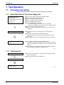
1. Test Operation ......................................................................................46
1.1 Procedure and Outline ........................................................................... 46
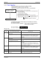
1.2 Operation When Power is Turned On .................................................... 49
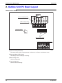
2. Outdoor Unit PC Board Layout .............................................................50
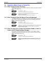
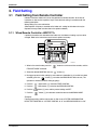
3. Field Setting ..........................................................................................51
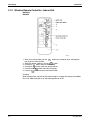
3.1 Field Setting from Remote Controller..................................................... 51
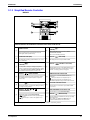
3.2 Field Setting from Outdoor Unit ............................................................. 62
3.3 Detail of Setting Mode............................................................................ 68
Part 7 Troubleshooting............................................................... 79
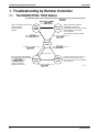
1. Troubleshooting by Remote Controller .................................................82
1.1
1.2
1.3
1.4
The INSPECTION / TEST Button .......................................................... 82
Self-Diagnosis by Wired Remote Controller........................................... 83
Self-Diagnosis by Wireless Remote Controller ...................................... 84
Operation of the Remote Controller’s Inspection /
Test Operation Button............................................................................ 86
1.5 Remote Controller Service Mode ........................................................... 87
2. List of Malfunction Code .......................................................................89
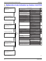
3. Malfunction Code Indication by Outdoor Unit PCB ...............................92
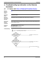
4. Troubleshooting by Indication on the Remote Controller ......................94
4.1
4.2
4.3
4.4
4.5
4.6
“A0” Indoor Unit: Error of External Protection Device ............................. 94
“A1” Indoor Unit: PC Board Defect .......................................................... 95
“A3” Indoor Unit: Malfunction of Drain Level Control System (S1L)........ 96
“A6” Indoor Unit: Fan Motor (M1F) Lock, Overload ................................ 98
“A7” Indoor Unit: Malfunction of Swing Flap Motor (MA)......................... 99
“A9” Indoor Unit: Malfunction of Moving Part of
Electronic Expansion Valve (20E)........................................................ 101
4.7 “AF” Indoor Unit: Drain Level above Limit ............................................. 103
4.8 “AJ” Indoor Unit: Malfunction of Capacity Determination Device.......... 104
ii
Table of Contents
SiUS25-501
4.9 “C4” Indoor Unit: Malfunction of Thermistor (R2T)
for Heat Exchanger .............................................................................. 105
4.10 “C5” Indoor Unit: Malfunction of Thermistor (R3T) for Gas Pipes ......... 106
4.11 “C9” Indoor Unit: Malfunction of Thermistor (R1T) for Suction Air ........ 107
4.12 “CJ” Indoor Unit: Malfunction of Thermostat Sensor in
Remote Controller ................................................................................ 108
4.13 “E1” Outdoor Unit: PC Board Defect...................................................... 109
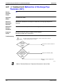
4.14 “E3” Outdoor Unit: Actuation of High Pressure Switch.......................... 110
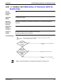
4.15 “E4” Outdoor Unit: Actuation of Low Pressure Switch .......................... 111
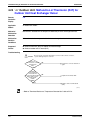
4.16 “E5” Outdoor Unit: Compressor Motor Lock.......................................... 113
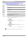
4.17 “E7” Outdoor Unit: Malfunction of Outdoor Unit Fan Motor ................... 114
4.18 “E9” Outdoor Unit: Malfunction of Moving Part of
Electronic Expansion Valve ................................................................. 116
4.19 “F3” Outdoor Unit: Abnormal Discharge Pipe Temperature .................. 118
4.20 “H9” Outdoor Unit: Malfunction of Thermistor (R1T) for Outdoor Air .... 119
4.21 “J3” Outdoor Unit: Malfunction of Discharge Pipe Thermistor (R3T).... 120
4.22 “J5” Outdoor Unit: Malfunction of Thermistor (R2T) for Suction Pipe... 121
4.23 “J6” Outdoor Unit: Malfunction of Thermistor (R4T) for
Outdoor Unit Heat Exchanger Deicer .................................................. 122
4.24 “J9” Outdoor Unit: Malfunction of Subcooling Heat Exchanger
Gas Pipe Thermistor (R5T) .................................................................. 123
4.25 “JA” Outdoor Unit: Malfunction of High Pressure Sensor ..................... 124
4.26 “JC” Outdoor Unit: Malfunction of Low Pressure Sensor ...................... 126
4.27 “L4” Outdoor Unit: Malfunction of Inverter Radiating Fin
Temperature Rise ................................................................................ 127
4.28 “L5” Outdoor Unit: Inverter Compressor Abnormal ............................... 128
4.29 “L8” Outdoor Unit: Inverter Current Abnormal....................................... 129
4.30 “L9” Outdoor Unit: Inverter Start up Error ............................................. 131
4.31 “LC” Outdoor Unit: Malfunction of Transmission between Inverter
and Control PC Board.......................................................................... 132
4.32 “P4” Outdoor Unit: Malfunction of Inverter Radiating Fin
Temperature Rise Sensor .................................................................... 134
4.33 “PJ” Outdoor Unit: Faulty Combination of Inverter and Fan Driver ....... 135
4.34 “UO” Outdoor Unit: Low Pressure Drop Due to Refrigerant
Shortage or Electronic Expansion Valve Failure.................................. 136
4.35 “U2” Outdoor Unit: Power Supply Insufficient or
Instantaneous Failure .......................................................................... 137
4.36 “U3” Outdoor Unit: Check Operation not Executed ............................... 139
4.37 “U4” Malfunction of Transmission between Indoor Units and
Outdoor Units....................................................................................... 140
4.38 “U5” Indoor Unit: Malfunction of Transmission between
Remote Controller and Indoor Unit ...................................................... 142
4.39 “U8” Indoor Unit: Malfunction of Transmission between Main and
Sub Remote Controllers....................................................................... 143
4.40 “U9” Indoor Unit: Malfunction of Transmission between Indoor
Units and Outdoor Units in the Same System ..................................... 144
4.41 “UA” Improper Combination of Indoor Units and Outdoor Units,
Indoor Units and Remote Controller .................................................... 146
4.42 “UC” Address Duplication of Centralized Controller............................... 147
Table of Contents
iii
SiUS25-501
4.43 “UE” Malfunction of Transmission between Centralized
Controller and Indoor Unit .................................................................... 148
4.44 “UF” System is not Set yet.................................................................... 150
4.45 “UH” Malfunction of System, Refrigerant System Address
Undefined............................................................................................. 151
5. Troubleshooting by Indication on the Central Remote Controller .......152
5.1 “M1” PC Board Defect ............................................................................ 152
5.2 “M8” Malfunction of Transmission between Optional Controllers
for Centralized Control ......................................................................... 153
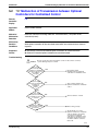
5.3 “MA” Improper Combination of Optional Controllers for
Centralized Control .............................................................................. 154
5.4 “MC” Address Duplication, Improper Setting.......................................... 156
6. Troubleshooting by Indication on the Unified ON/OFF Controller.......157
6.1 Operation Lamp Blinks......................................................................... 157
6.2 Display “Under Centralized Control” Blinks (Repeats Single Blink) ..... 159
6.3 Display “Under Centralized Control” Blinks (Repeats Double Blink).... 162
7. Troubleshooting (OP: Schedule Timer) ..............................................163
7.1 “UE” Malfunction of Transmission between Centralized
Controller and Indoor Unit .................................................................... 163
7.2 “M1” PC Board Defect ............................................................................ 165
7.3 “M8” Malfunction of Transmission between Optional Controllers
for Centralized Control ......................................................................... 166
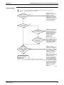
7.4 “MA” Improper Combination of Optional Controllers for
Centralized Control .............................................................................. 167
7.5 “MC” Address Duplication, Improper Setting.......................................... 169
8. Check ..................................................................................................170
Part 8 Appendix ........................................................................ 173
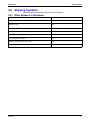
1. Piping Diagrams..................................................................................174
1.1 Outdoor Unit......................................................................................... 174
1.2 Indoor Unit ........................................................................................... 175
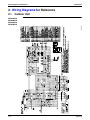
2. Wiring Diagrams for Reference...........................................................176
2.1 Outdoor Unit......................................................................................... 176
2.2 Indoor Unit ........................................................................................... 177
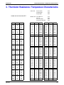
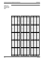
3. Thermistor Resistance / Temperature Characteristics........................179
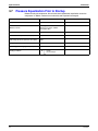
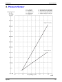
4. Pressure Sensor .................................................................................181
Part 9 Precautions for New Refrigerant (R-410A) ................... 183
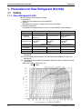
1. Precautions for New Refrigerant (R-410A) .........................................184
1.1 Outline.................................................................................................. 184
1.2 Service Tools ....................................................................................... 186
Index
............................................................................................ i
Drawings & Flow Charts .................................................................v
iv
Table of Contents
SiUS25-501
Introduction
1. Introduction
1.1
Safety Cautions
Cautions and
Warnings
Be sure to read the following safety cautions before conducting repair work.
Warning” and “
Caution”. The “
The caution items are classified into “
Warning”
items are especially important since they can lead to death or serious injury if they are not
followed closely. The “
Caution” items can also lead to serious accidents under some
conditions if they are not followed. Therefore, be sure to observe all the safety caution items
described below.
About the pictograms
This symbol indicates an item for which caution must be exercised.
The pictogram shows the item to which attention must be paid.
This symbol indicates a prohibited action.
The prohibited item or action is shown inside or near the symbol.
This symbol indicates an action that must be taken, or an instruction.
The instruction is shown inside or near the symbol.
After the repair work is complete, be sure to conduct a test operation to ensure that the
equipment operates normally, and explain the cautions for operating the product to the
customer
1.1.1 Caution in Repair
Warning
Be sure to disconnect the power cable plug from the plug socket before
disassembling the equipment for a repair.
Working on the equipment that is connected to a power supply can cause an
electrical shook.
If it is necessary to supply power to the equipment to conduct the repair or
inspecting the circuits, do not touch any electrically charged sections of the
equipment.
If the refrigerant gas discharges during the repair work, do not touch the
discharging refrigerant gas.
The refrigerant gas can cause frostbite.
When disconnecting the suction or discharge pipe of the compressor at the
welded section, release the refrigerant gas completely at a well-ventilated
place first.
If there is a gas remaining inside the compressor, the refrigerant gas or
refrigerating machine oil discharges when the pipe is disconnected, and it can
cause injury.
If the refrigerant gas leaks during the repair work, ventilate the area. The
refrigerant gas can generate toxic gases when it contacts flames.
The step-up capacitor supplies high-voltage electricity to the electrical
components of the outdoor unit.
Be sure to discharge the capacitor completely before conducting repair work.
A charged capacitor can cause an electrical shock.
Do not start or stop the air conditioner operation by plugging or unplugging the
power cable plug.
Plugging or unplugging the power cable plug to operate the equipment can
cause an electrical shock or fire.
v
Introduction
SiUS25-501
Caution
Do not repair the electrical components with wet hands.
Working on the equipment with wet hands can cause an electrical shock.
Do not clean the air conditioner by splashing water.
Washing the unit with water can cause an electrical shock.
Be sure to provide the grounding when repairing the equipment in a humid or
wet place, to avoid electrical shocks.
Be sure to turn off the power switch and unplug the power cable when cleaning
the equipment.
The internal fan rotates at a high speed, and cause injury.
Do not tilt the unit when removing it.
The water inside the unit can spill and wet the furniture and floor.
Be sure to check that the refrigerating cycle section has cooled down
sufficiently before conducting repair work.
Working on the unit when the refrigerating cycle section is hot can cause burns.
Use the welder in a well-ventilated place.
Using the welder in an enclosed room can cause oxygen deficiency.
1.1.2 Cautions Regarding Products after Repair
Warning
Be sure to use parts listed in the service parts list of the applicable model and
appropriate tools to conduct repair work. Never attempt to modify the
equipment.
The use of inappropriate parts or tools can cause an electrical shock,
excessive heat generation or fire.
When relocating the equipment, make sure that the new installation site has
sufficient strength to withstand the weight of the equipment.
If the installation site does not have sufficient strength and if the installation
work is not conducted securely, the equipment can fall and cause injury.
Be sure to install the product correctly by using the provided standard
installation frame.
Incorrect use of the installation frame and improper installation can cause the
equipment to fall, resulting in injury.
Be sure to install the product securely in the installation frame mounted on a
window frame.
If the unit is not securely mounted, it can fall and cause injury.
vi
For integral units
only
For integral units
only
SiUS25-501
Introduction
Warning
Be sure to use an exclusive power circuit for the equipment, and follow the
technical standards related to the electrical equipment, the internal wiring
regulations and the instruction manual for installation when conducting
electrical work.
Insufficient power circuit capacity and improper electrical work can cause an
electrical shock or fire.
Be sure to use the specified cable to connect between the indoor and outdoor
units. Make the connections securely and route the cable properly so that there
is no force pulling the cable at the connection terminals.
Improper connections can cause excessive heat generation or fire.
When connecting the cable between the indoor and outdoor units, make sure
that the terminal cover does not lift off or dismount because of the cable.
If the cover is not mounted properly, the terminal connection section can cause
an electrical shock, excessive heat generation or fire.
Do not damage or modify the power cable.
Damaged or modified power cable can cause an electrical shock or fire.
Placing heavy items on the power cable, and heating or pulling the power cable
can damage the cable.
Do not mix air or gas other than the specified refrigerant in the refrigerant
system.
If air enters the refrigerating system, an excessively high pressure results,
causing equipment damage and injury.
If the refrigerant gas leaks, be sure to locate the leak and repair it before
charging the refrigerant. After charging refrigerant, make sure that there is no
refrigerant leak.
If the leak cannot be located and the repair work must be stopped, be sure to
perform pump-down and close the service valve, to prevent the refrigerant gas
from leaking into the room. The refrigerant gas itself is harmless, but it can
generate toxic gases when it contacts flames, such as fan and other heaters,
stoves and ranges.
When replacing the coin battery in the remote controller, be sure to disposed
of the old battery to prevent children from swallowing it.
If a child swallows the coin battery, see a doctor immediately.
Caution
Installation of a leakage breaker is necessary in some cases depending on the
conditions of the installation site, to prevent electrical shocks.
Do not install the equipment in a place where there is a possibility of
combustible gas leaks.
If a combustible gas leaks and remains around the unit, it can cause a fire.
Be sure to install the packing and seal on the installation frame properly.
For integral units
If the packing and seal are not installed properly, water can enter the room and only
wet the furniture and floor.
1.1.3 Inspection after Repair
Warning
Check to make sure that the power cable plug is not dirty or loose, then insert
the plug into a power outlet all the way.
If the plug has dust or loose connection, it can cause an electrical shock or fire.
vii
Introduction
SiUS25-501
Warning
If the power cable and lead wires have scratches or deteriorated, be sure to
replace them.
Damaged cable and wires can cause an electrical shock, excessive heat
generation or fire.
Do not use a joined power cable or extension cable, or share the same power
outlet with other electrical appliances, since it can cause an electrical shock,
excessive heat generation or fire.
Caution
Check to see if the parts and wires are mounted and connected properly, and
if the connections at the soldered or crimped terminals are secure.
Improper installation and connections can cause excessive heat generation,
fire or an electrical shock.
If the installation platform or frame has corroded, replace it.
Corroded installation platform or frame can cause the unit to fall, resulting in
injury.
Check the grounding, and repair it if the equipment is not properly grounded.
Improper grounding can cause an electrical shock.
Be sure to measure the insulation resistance after the repair, and make sure
that the resistance is 1 Mohm or higher.
Faulty insulation can cause an electrical shock.
Be sure to check the drainage of the indoor unit after the repair.
Faulty drainage can cause the water to enter the room and wet the furniture
and floor.
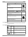
1.1.4 Using Icons
Icons are used to attract the attention of the reader to specific information. The meaning of each
icon is described in the table below:
1.1.5 Using Icons List
Icon
Type of
Information
Description
Note
A “note” provides information that is not indispensable, but may
nevertheless be valuable to the reader, such as tips and tricks.
Caution
A “caution” is used when there is danger that the reader, through
incorrect manipulation, may damage equipment, loose data, get
an unexpected result or has to restart (part of) a procedure.
Warning
A “warning” is used when there is danger of personal injury.
Reference
A “reference” guides the reader to other places in this binder or
in this manual, where he/she will find additional information on a
specific topic.
Note:
Caution
Warning
viii
SiUS25-501
Part 1
General Information
1. Model Names and Power Supply............................................................2
2. External Appearance ..............................................................................3
2.1 Indoor Units.............................................................................................. 3
2.2 Outdoor Units........................................................................................... 3
General Information
1
Model Names and Power Supply
SiUS25-501
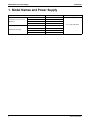
1. Model Names and Power Supply
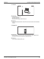
Indoor Unit
Ceiling Mounted Cassette Type
(Multi Flow)
Ceiling Suspended Type
2
Outdoor Unit
FCQ24MVJU
RZQ24MVJU
FCQ30MVJU
RZQ30MVJU
FCQ36MVJU
RZQ36MVJU
FCQ42MVJU
RZQ42MVJU
FHQ24MVJU
RZQ24MVJU
FHQ30MVJU
RZQ30MVJU
FHQ36MVJU
RZQ36MVJU
FHQ42MVJU
RZQ42MVJU
Power Supply
VJ : 1φ, 208~230V, 60Hz
General Information
SiUS25-501
External Appearance
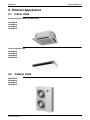
2. External Appearance
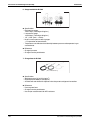
2.1
Indoor Units
Ceiling Mounted Cassette Type (Multi Flow)
FCQ24MVJU
FCQ30MVJU
FCQ36MVJU
FCQ42MVJU
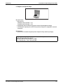
Ceiling Suspended Type
FHQ24MVJU
FHQ30MVJU
FHQ36MVJU
FHQ42MVJU
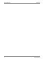
2.2
Outdoor Units
RZQ24MVJU
RZQ30MVJU
RZQ36MVJU
RZQ42MVJU
General Information
3
External Appearance
4
SiUS25-501
General Information
SiUS25-501
Part 2
Specifications
1. Specifications..........................................................................................6
1.1 FCQ ......................................................................................................... 6
1.2 FHQ ......................................................................................................... 8
Specifications
5
Specifications
SiUS25-501
1. Specifications
1.1
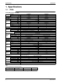
FCQ
Ceiling Mounted Cassette Type
Model
Indoor Unit
Outdoor Unit
∗1 Cooling Capacity
∗2 Heating Capacity
Indoor Unit
Dimensions H×W×D
Type
Coil
Rows×Stages×FPI
Face Area
Model
Type
Fan
Motor Output
Air Flow Rate (H/L)
Air Filter
Mass (Weight)
Liquid
Piping
Connections Gas
Drain
Wired
Remote Controller (Option)
Wireless
Model
Color
Decoration
Panels
Dimensions H×W×D
(Option)
Air Filter
Weight
Outdoor Unit
Color
Dimensions H×W×D
Type
Coil
Rows×Stages×FPI
Face Area
Model
Comp.
Type
Motor Output
Model
Type
Fan
Motor Output
Air Flow Rate
Mass (Weight)
Liquid
Piping
Connections Gas
Drain
Btu/h
Btu/h
in.
FCQ30MVJU
RZQ24MVJU
24,000
27,000
FCQ24MVJU
11–3/8 × 33–1/8 × 33–1/8
RZQ30MVJU
30,000
34,000
FCQ30MVJU
11–3/8 × 33–1/8 × 33–1/8
Cross Fin Coil
2×12×17
5.35
QTS45A17M
ft²
2×12×17
5.35
QTS45A17M
Turbo Fan
W
cfm
90
(Cooling) 790/670 (Heating) 870/670
—
73
φ3/8 (Flare Connection)
φ5/8 (Flare Connection)
VP25 (External Dia. 1–1/4, Internal Dia. 1)
Lbs
in.
in.
in.
90
900/790
—
73
φ3/8 (Flare Connection)
φ5/8 (Flare Connection)
VP25 (External Dia. 1–1/4, Internal Dia. 1)
BRC1C71
BRC7C812
BYC125K–W19
White (10Y9/0.5)
in.
1–5/8 × 37–3/8 × 37–3/8
Resin Net (with Mold Resistant)
11
RZQ24MVJU
Lbs
1–5/8 × 37–3/8 × 37–3/8
Resin Net (with Mold Resistant)
11
RZQ30MVJU
Ivory White (5Y7.5/1)
in.
52–15/16 × 35–7/16 × 12–5/8
52–15/16 × 35–7/16 × 12–5/8
Cross Fin Coil
2×60×13
12.2
JT100FCVDK@4
ft²
2×60×13
12.2
JT100FCVDK@4
Hermetically Sealed Scroll Type
kW
W
cfm
Lbs
in.
in.
in.
Safety Devices
Refrigerant Control
Standard Length
Ref. Piping
Max. Length
Max. Height Difference
Model
Refrigerant
Charge (Factory Charge)
Model
Ref. Oil
Charge
Drawing No.
FCQ24MVJU
ft
ft
ft
Lbs
L
1.6
KFD–325–70–8A
2.0
KFD–325–70–8A
Propeller Fan
70×2
70×2
3,740
3,740
310
310
φ3/8 (Flare Connection)
φ3/8 (Flare Connection)
φ5/8 (Flare Connection)
φ5/8 (Flare Connection)
φ1 (Hole)
φ1 (Hole)
High Pressure Switch. Outdoor Fan Driver Overload Protector. Thermal Protector for Indoor Fan Motor. Inverter Overload
Protector. Fusible Plugs. Fuse.
Electronic Expansion Valve
25
25
230
230
164
164
R-410A
R-410A
12.8
12.8
Refer to the name plate of compressor.
1.6
1.6
C : 4D049128
Note:
1. The above data are based on the following conditions.
Cooling ∗1
Heating ∗2
Equivalent Piping Length
Hz, Volts
Indoor : 80°FDB, 67°FWB
Indoor : 70°FDB
60Hz, 230V
Outdoor : 95°FDB
Outdoor : 47°FDB, 43°FWB 25ft (Level Difference : 0)
2. Capacities are net, including a deduction for cooling (an addition for heating) for indoor fan motor heat.
6
Specifications
SiUS25-501
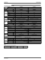
Specifications
Ceiling Mounted Cassette Type
Model
Indoor Unit
Outdoor Unit
∗1 Cooling Capacity
∗2 Heating Capacity
Indoor Unit
Dimensions H×W×D
Type
Coil
Rows×Stages×FPI
Face Area
Model
Type
Fan
Motor Output
Air Flow Rate (H/L)
Air Filter
Mass (Weight)
Liquid
Piping
Connections Gas
Drain
Wired
Remote Controller (Option)
Wireless
Model
Color
Decoration
Panels
Dimensions H×W×D
(Option)
Air Filter
Weight
Outdoor Unit
Color
Dimensions H×W×D
Type
Coil
Rows×Stages×FPI
Face Area
Model
Comp.
Type
Motor Output
Model
Type
Fan
Motor Output
Air Flow Rate
Mass (Weight)
Liquid
Piping
Connections Gas
Drain
Btu/h
Btu/h
in.
FCQ42MVJU
RZQ36MVJU
36,000
39,500
FCQ36MVJU
11–3/8 × 33–1/8 × 33–1/8
RZQ42MVJU
40,500
41,500
FCQ36MVJU
11–3/8 × 33–1/8 × 33–1/8
Cross Fin Coil
2×12×17
5.35
QTS45A17M
ft²
2×12×17
5.35
QTS45A17M
Turbo Fan
W
cfm
90
950/790
—
74
φ3/8 (Flare Connection)
φ5/8 (Flare Connection)
VP25 (External Dia. 1–1/4, Internal Dia. 1)
Lbs
in.
in.
in.
90
1,030/870
—
74
φ3/8 (Flare Connection)
φ5/8 (Flare Connection)
VP25 (External Dia. 1–1/4, Internal Dia. 1)
BRC1C71
BRC7C812
BYC125K–W19
White (10Y9/0.5)
in.
1–5/8 × 37–3/8 × 37–3/8
Resin Net (with Mold Resistant)
11
RZQ36MVJU
Lbs
1–5/8 × 37–3/8 × 37–3/8
Resin Net (with Mold Resistant)
11
RZQ42MVJU
Ivory White (5Y7.5/1)
in.
52–15/16 × 35–7/16 × 12–5/8
52–15/16 × 35–7/16 × 12–5/8
Cross Fin Coil
2×60×13
12.2
JT100FCVDK@4
ft²
2×60×13
12.2
JT100FCVDK@4
Hermetically Sealed Scroll Type
kW
W
cfm
Lbs
in.
in.
in.
Safety Devices
Refrigerant Control
Standard Length
Ref. Piping
Max. Length
Max. Height Difference
Model
Refrigerant
Charge (Factory Charge)
Model
Ref. Oil
Charge
Drawing No.
FCQ36MVJU
ft
ft
ft
Lbs
L
2.5
KFD–325–70–8A
3.0
KFD–325–70–8A
Propeller Fan
70×2
70×2
3,740
3,740
310
310
φ3/8 (Flare Connection)
φ3/8 (Flare Connection)
φ5/8 (Flare Connection)
φ5/8 (Flare Connection)
φ1 (Hole)
φ1 (Hole)
High Pressure Switch. Outdoor Fan Driver Overload Protector. Thermal Protector for Indoor Fan Motor. Inverter Overload
Protector. Fusible Plugs. Fuse.
Electronic Expansion Valve
25
25
230
230
164
164
R-410A
R-410A
12.8
12.8
Refer to the name plate of compressor.
1.6
1.6
C : 4D049128
Note:
1. The above data are based on the following conditions.
Cooling ∗1
Heating ∗2
Equivalent Piping Length
Hz, Volts
Indoor : 80°FDB, 67°FWB
Indoor : 70°FDB
60Hz, 230V
Outdoor : 95°FDB
Outdoor : 47°FDB, 43°FWB 25ft (Level Difference : 0)
2. Capacities are net, including a deduction for cooling (an addition for heating) for indoor fan motor heat.
Specifications
7
Specifications
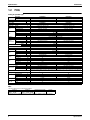
1.2
SiUS25-501
FHQ
Ceiling Suspended Type
Model
Indoor Unit
Outdoor Unit
∗1 Cooling Capacity
∗2 Heating Capacity
Indoor Unit
Color
Dimensions H×W×D
Type
Coil
Rows×Stages×FPI
Face Area
Model
Type
Fan
Motor Output
Air Flow Rate (H/L)
Air Filter
Mass (Weight)
Liquid
Piping
Connections Gas
Drain
Wired
Remote Controller (Option)
Wireless
Outdoor Unit
Color
Dimensions H×W×D
Type
Coil
Rows×Stages×FPI
Face Area
Model
Comp.
Type
Motor Output
Model
Type
Fan
Motor Output
Air Flow Rate
Mass (Weight)
Liquid
Piping
Connections Gas
Drain
FHQ24MVJU
FHQ30MVJU
Btu/h
Btu/h
RZQ24MVJU
24,000
27,000
FHQ24MVJU
RZQ30MVJU
30,000
34,000
FHQ30MVJU
in.
7–11/16 × 62–5/8 × 26–3/4
White (10Y9/0.5)
ft²
2×12×15 + 2×10×15
3.66+2.95
—
W
cfm
130
790/670
2×12×15 + 2×10×15
3.66+2.95
—
Sirocco Fan
Lbs
in.
in.
in.
in.
ft²
kW
W
cfm
Lbs
in.
in.
in.
Safety Devices
Refrigerant Control
Standard Length
Ref. Piping
Max. Length
Max. Height Difference
Model
Refrigerant
Charge (Factory Charge)
Model
Ref. Oil
Charge
Drawing No.
7–11/16 × 62–5/8 × 26–3/4
Cross Fin Coil
ft
ft
ft
Lbs
L
130
790/670
Resin Net (With Mold Resistant)
90
90
φ3/8 (Flare Connection)
φ3/8 (Flare Connection)
φ5/8 (Flare Connection)
φ5/8 (Flare Connection)
VP20 (External Dia. 1, Internal Dia. 3/4)
VP20 (External Dia. 1, Internal Dia. 3/4)
BRC1C71
BRC7E83
RZQ24MVJU
RZQ30MVJU
Ivory White (5Y7.5/1)
52–15/16 × 35–7/16 × 12–5/8
52–15/16 × 35–7/16 × 12–5/8
Cross Fin Coil
2×60×13
2×60×13
12.2
12.2
JT100FCVDK@4
JT100FCVDK@4
Hermetically Sealed Scroll Type
1.6
2.0
KFD–325–70–8A
KFD–325–70–8A
Propeller Fan
70×2
70×2
3,740
3,740
310
310
φ3/8 (Flare Connection)
φ3/8 (Flare Connection)
φ5/8 (Flare Connection)
φ5/8 (Flare Connection)
φ1 (Hole)
φ1 (Hole)
High Pressure Switch. Outdoor Fan Driver Overload Protector. Thermal Protector for Indoor Fan Motor. Inverter Overload
Protector. Fusible Plugs. Fuse.
Electronic Expansion Valve
25
25
230
230
164
164
R-410A
R-410A
12.8
12.8
Refer to the name plate of compressor.
1.6
1.6
C : 4D049325
Note:
1. The above data are based on the following conditions.
Cooling ∗1
Heating ∗2
Equivalent Piping Length
Hz, Volts
Indoor : 80°FDB, 67°FWB
Indoor : 70°FDB
60Hz, 230V
Outdoor : 95°FDB
Outdoor : 47°FDB, 43°FWB 25ft (Level Difference : 0)
2. Capacities are net, including a deduction for cooling (an addition for heating) for indoor fan motor heat.
8
Specifications
SiUS25-501
Specifications
Ceiling Suspended Type
Model
Indoor Unit
Outdoor Unit
∗1 Cooling Capacity
∗2 Heating Capacity
Indoor Unit
Color
Dimensions H×W×D
Type
Coil
Rows×Stages×FPI
Face Area
Model
Type
Fan
Motor Output
Air Flow Rate (H/L)
Air Filter
Mass (Weight)
Liquid
Piping
Connections Gas
Drain
Wired
Remote Controller (Option)
Wireless
Outdoor Unit
Color
Dimensions H×W×D
Type
Coil
Rows×Stages×FPI
Face Area
Model
Comp.
Type
Motor Output
Model
Type
Fan
Motor Output
Air Flow Rate
Mass (Weight)
Liquid
Piping
Connections Gas
Drain
FHQ36MVJU
FHQ42MVJU
Btu/h
Btu/h
RZQ36MVJU
36,000
37,500
FHQ36MVJU
RZQ42MVJU
40,500
39,500
FHQ42MVJU
in.
7–11/16 × 62–5/8 × 26–3/4
White (10Y9/0.5)
ft²
2×12×15 + 2×10×15
3.66+2.95
—
W
cfm
130
830/670
2×12×15 + 2×10×15
3.66+2.95
—
Sirocco Fan
Lbs
in.
in.
in.
in.
ft²
kW
W
cfm
Lbs
in.
in.
in.
Safety Devices
Refrigerant Control
Standard Length
Ref. Piping
Max. Length
Max. Height Difference
Model
Refrigerant
Charge (Factory Charge)
Model
Ref. Oil
Charge
Drawing No.
7–11/16 × 62–5/8 × 26–3/4
Cross Fin Coil
ft
ft
ft
Lbs
L
130
850/700
Resin Net (With Mold Resistant)
90
90
φ3/8 (Flare Connection)
φ3/8 (Flare Connection)
φ5/8 (Flare Connection)
φ5/8 (Flare Connection)
VP20 (External Dia. 1, Internal Dia. 3/4)
VP20 (External Dia. 1, Internal Dia. 3/4)
BRC1C71
BRC7E83
RZQ36MVJU
RZQ42MVJU
Ivory White (5Y7.5/1)
52–15/16 × 35–7/16 × 12–5/8
52–15/16 × 35–7/16 × 12–5/8
Cross Fin Coil
2×60×13
2×60×13
12.2
12.2
JT100FCVDK@4
JT100FCVDK@4
Hermetically Sealed Scroll Type
2.5
3.0
KFD–325–70–8A
KFD–325–70–8A
Propeller Fan
70×2
70×2
3,740
3,740
310
310
φ3/8 (Flare Connection)
φ3/8 (Flare Connection)
φ5/8 (Flare Connection)
φ5/8 (Flare Connection)
φ1 (Hole)
φ1 (Hole)
High Pressure Switch. Outdoor Fan Driver Overload Protector. Thermal Protector for Indoor Fan Motor. Inverter Overload
Protector. Fusible Plugs. Fuse.
Electronic Expansion Valve
25
25
230
230
164
164
R-410A
R-410A
12.8
12.8
Refer to the name plate of compressor.
1.6
1.6
C : 4D049325
Note:
1. The above data are based on the following conditions.
Cooling ∗1
Heating ∗2
Equivalent Piping Length
Hz, Volts
Indoor : 80°FDB, 67°FWB
Indoor : 70°FDB
60Hz, 230V
Outdoor : 95°FDB
Outdoor : 47°FDB, 43°FWB 25ft (Level Difference : 0)
2. Capacities are net, including a deduction for cooling (an addition for heating) for indoor fan motor heat.
Specifications
9
Specifications
10
SiUS25-501
Specifications
SiUS25-501
Part 3
List of Electrical and
Functional Parts
1. List of Electrical and Functional Parts ...................................................12
1.1 Outdoor Units......................................................................................... 12
1.2 Indoor Units............................................................................................ 13
List of Electrical and Functional Parts
11
List of Electrical and Functional Parts
SiUS25-501
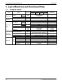
1. List of Electrical and Functional Parts
1.1
Outdoor Units
Item
Compressor
Fan motor
Functional
parts
Name
Type
Output
Crankcase heater (INV)
Motor
Over-current relay
Electronic expansion Cooling
valve (Main)
Heating
Electronic expansion Cooling
valve (Subcool)
Heating
Solenoid valve (Hot gas)
Solenoid valve (Receiver gas
charge)
4 way valve
Inverter
Pressure switch (INV)
Pressurerelated parts
Thermistor
12
Fusible plug
Pressure sensor (HP)
Pressure sensor (LP)
For outdoor air
For suction pipe
Main
For discharge pipe
PC
board For heat exchanger
For subcooling heat
exchanger
Symbol
M1C
E1HC
M1F·M2F
—
RZQ24
MVJU
Model
RZQ30
RZQ36
MVJU
MVJU
RZQ42
MVJU
JT100FCVDK@4
3.2kW
Remark
(PCB terminal)
—
A1P X6A
—
—
A1P X26A
Y1S
33W
0.07kW
3.2A
1400pls
PI control
PI control
0pls
TEV1620DQ2
Y2S
TEV1620DQ2
A1P X3A
Y3S
A1P X5A
—
S1NPH
S1NPL
R1T
R2T
R3T
R4T
VT40100
ACB-4UB10
ON: 580+0/-22 psi OFF: 435±22 psi
FPGH-3D 158~167°F
PS8051A 0~602 psi
PS8051A -7~247 psi
3.5~360kΩ
3.5~360kΩ
3.5~400kΩ
3.5~360kΩ
—
A1P X46A
A1P X45A
A1P X44A
A1P X37A 1-2Pin
A1P X34A 1-2Pin
A1P X37A 3-4Pin
R5T
3.5~360kΩ
A1P X37A 5-6Pin
Y1E
Y2E
S1PH
A1P X28A
A1P X2A
A2P X60A
List of Electrical and Functional Parts
SiUS25-501
1.2
List of Electrical and Functional Parts
Indoor Units
Model
Parts Name
Remote
Controller
FCQ
24MVJU
FCQ
30MVJU
FCQ
36MVJU
Wired Remote
Controller
BRC1C71
Wireless Remote
Controller
BRC7C812
Fan Motor
Motors
Symbol
Capacitor, fan motor
M1F
C1
1φ45W 6P
1φ90W 6P
Thermal Protector 266°F : OFF
3.5µF 450VAC
176°F : ON
5.0µF 450VAC
M1P
PLD-12230DM
Thermal Fuse 293°F
Swing Motor
M1S
MP35HCA [3P007482-1]
Thermistor (Suction Air)
R1T
ST8601A-1 φ4 L250
20kΩ (77°F)
(for Heat
Thermistors Thermistor
Exchanger High Temp.)
R3T
ST8605-3 φ8 L630
20kΩ (77°F)
R2T
ST8602A-3 φ6 L630
20kΩ (77°F)
Others
Remark
Option
Drain Pump
Thermistor (Heat
Exchanger)
FCQ
42MVJU
Float Switch
S1L
FS-0211
Fuse
F1U
250V 5A φ5.2
Transformer
T1R
TR25H25R0
Model
Parts Name
Remote
Controller
Symbol
FHQ
24MVJU
FHQ
30MVJU
FHQ
36MVJU
Wired Remote
Controller
BRC1C71
Wireless Controller
BRC7E83
FHQ
42MVJU
Option
1φ130W
Fan Motor
M1F
Capacitor for Fan Motor
C1R
9.0µF-450V
Swing Motor
M1S
MT8-L[3P058751-1]
AC200~240V
Thermistor (Suction Air)
R1T
ST8601A-1 φ4 L250
20kΩ (77°F)
(for Heat
Thermistors Thermistor
Exchanger High Temp.)
R3T
ST8605-6 φ8 L = 1250
20kΩ (77°F)
ST8605-6 φ8 L = 1250
20kΩ (77°F)
R2T
ST8602A-6 φ6 L = 1250
20kΩ (77°F)
ST8602A-6 φ6 L = 1250
20kΩ (77°F)
Motors
Thermistor (Heat
Exchanger)
Others
Thermal protector 266°F : OFF
Fuse
F1U
250V 5A
Transformer
T1R
TR25H25R0
List of Electrical and Functional Parts
Remark
176°F : ON
13
List of Electrical and Functional Parts
14
SiUS25-501
List of Electrical and Functional Parts
SiUS25-501
Part 4
Refrigerant Circuit
1. Refrigerant Circuit .................................................................................16
1.1 RZQ24·30·36·42MVJU........................................................................... 16
2. Functional Parts Layout ........................................................................18
2.1 RZQ24·30·36·42MVJU........................................................................... 18
Refrigerant Circuit
15
Refrigerant Circuit
SiUS25-501
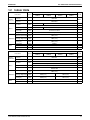
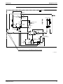
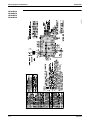
1. Refrigerant Circuit
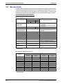
1.1
RZQ24·30·36·42MVJU
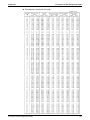
No. in
refrigerant Symbol
system
diagram
Major Function
A
M1C
Inverter compressor (INV)
Inverter compressor is operated on frequencies between 52 Hz and 177 Hz by using
the inverter.
17 steps
D
M1F
M2F
Inverter fan
Since the system is of air heat exchanging type, the fan is operated at 8-step rotation
speed by using the inverter.
E
Y1E
Electronic expansion valve
(Main: EV1)
While in heating operation, PI control is applied to keep the outlet superheated degree
of air heat exchanger constant.
F
Y2E
Electronic expansion valve
(Subcool: EV2)
PI control is applied to keep the outlet superheated degree of subcooling heat
exchanger constant.
G
Y1S
Solenoid valve (Hot gas: SVP) Used to prevent the low pressure from transient falling.
J
Y2S
Solenoid valve (Receiver gas
discharging: SVG)
Y3S
Four way valve
M
16
Name
Used to collect refrigerant to receiver.
Used to switch the operation mode between cooling and heating.
N
S1NPH High pressure sensor
Used to detect high pressure.
O
S1NPL Low pressure sensor
Used to detect low pressure.
P
S1PH
S
HP pressure switch (For INV
compressor)
In order to prevent the increase of high pressure when a malfunction occurs, this
switch is activated at high pressure of 580 psi or more to stop the compressor
operation.
—
Fusible plug
In order to prevent the increase of pressure when abnormal heating is caused by fire
or others, the fusible part of the plug is molten at a temperature of 158 to 167°F to
release the pressure into the atmosphere.
T
—
Pressure regulating valve 1
(Receiver to discharge pipe)
This valve opens at a pressure of 290 to 390 psi for prevention of pressure increase,
thus resulting in no damage of functional parts due to the increase of pressure in
transportation or storage.
1
R1T
Thermistor (Outdoor air: Ta)
Used to detect outdoor temperature, correct discharge pipe temperature, and others.
2
R2T
Thermistor (Suction pipe: Ts)
used to detect suction pipe temperature, keep the suction superheated degree
constant in heating operation, and others.
3
R3T
Thermistor (INV discharge
pipe: Tdi)
used to detect discharge pipe temperature, make the temperature protection control of
compressor, and others.
4
R4T
Thermistor (Heat exchanger
deicer: Tb)
Used to detect liquid pipe temperature of air heat exchanger, determine defrosting
operation, and others.
5
R5T
Thermistor (Subcooling heat
exchanger gas pipe: Tsh)
Used to detect gas pipe temperature on the evaporation side of subcooling heat
exchanger, keep the superheated degree at the outlet of subcooling heat exchanger
constant, and others.
Refrigerant Circuit
SiUS25-501
Refrigerant Circuit
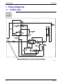
�
M
Four way
valve
T
N
Service port
High pressure SP
sensor
Oil
separator
Pressure
regulating valve
Filter
Heat exchanger
D
�
P
Filter
G
Capillary
tube
SV
�
HPS
Solenoid
valve
High pressure
switch
�
D
A
Compressor
�
SP
O
Low pressure
sensor
E
Check
valve
Check
valve
Check
valve
Check
valve
Filter
S
Fusible
plug
Double pipe
heat exchanger
Electronic
expansion valve
Receiver
SV
J
Filter
F
Filter
Solenoid
valve
Electronic
expansion valve
Filter
Heat
exchanger
pipe
Stop valve (With service port on field piping side φ6.4mm flare connection)
C : 3D047385
Refrigerant Circuit
17
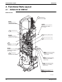
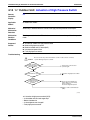
Functional Parts Layout
SiUS25-501
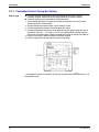
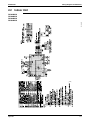
2. Functional Parts Layout
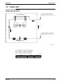
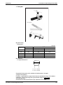
2.1
RZQ24·30·36·42MVJU
Birds-eye view
Y2S Solenoid valve
(Connector color : PINK)
S1NPH
High pressure sensor
(Connector color : RED)
S1NPH
High pressure sensor lead wire
(Connector color : RED)
(Low voltage)
Y3S Four way valve coil
S1NPL
Low pressure sensor
Y1E Electronic expansion valve
(Connector color : BLUE)
Y2E Electronic expansion valve
R3T
Discharge pipe thermistor
lead wire
S1NPL
Low pressure sensor lead wire
(Connector color : BLUE)
(Low voltage)
Y3S Four way valve lead wire
Y1S Solenoid valve
(Connector color : WHITE)
(Connector color : BLUE)
(High voltage)
Y2S Solenoid valve lead wire
(Connector color : PINK)
(High voltage)
Y1S Solenoid valve lead wire
(Connector color : WHITE)
(High voltage)
E1HC Crankcase heater lead wire
(Connector color : GRAY)
(High voltage)
1P152123H
18
Refrigerant Circuit
SiUS25-501
Part 5
Function
1. Operation Mode ....................................................................................20
2. Basic Control.........................................................................................21
2.1
2.2
2.3
2.4
Normal Operation................................................................................... 21
Compressor PI Control .......................................................................... 22
Electronic Expansion Valve PI Control .................................................. 23
Cooling Operation Fan Control .............................................................. 24
3. Special Control......................................................................................25
3.1
3.2
3.3
3.4
3.5
3.6
3.7
Startup Control....................................................................................... 25
Oil Return Operation .............................................................................. 26
Defrosting Operation.............................................................................. 28
Pump-down Residual Operation ............................................................ 29
Restart Standby ..................................................................................... 30
Stopping Operation ................................................................................ 31
Pressure Equalization Prior to Startup ................................................... 32
4. Protection Control .................................................................................33
4.1
4.2
4.3
4.4
High Pressure Protection Control .......................................................... 33
Low Pressure Protection Control ........................................................... 34
Discharge Pipe Protection Control ......................................................... 35
Inverter Protection Control ..................................................................... 36
5. Other Control ........................................................................................37
5.1 Heating Operation Prohibition ................................................................ 37
6. Outline of Control (Indoor Unit) .............................................................38
6.1
6.2
6.3
6.4
6.5
Function
Drain Pump Control ............................................................................... 38
Louver Control for Preventing Ceiling Dirt ............................................. 40
Thermostat Sensor in Remote Controller .............................................. 41
Freeze Prevention.................................................................................. 43
View of Operations of Swing Flaps ........................................................ 44
19
Operation Mode
SiUS25-501
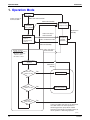
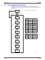
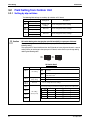
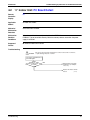
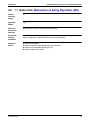
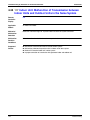
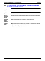
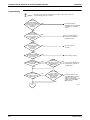
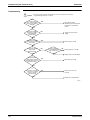
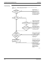
1. Operation Mode
Operation in
stop mode
Indoor unit stop or
thermostat OFF
Indoor unit thermostat ON
Malfunction/Standby
Restart standby
(Compressor stop)
Pressure
equalization
prior to startup
Malfunction/
Standby
Indoor unit stop or
thermostat OFF
Startup control
• Cooling startup
control
• Heating startup
control
Indoor unit thermostat ON
Pump-down
residual
operation
Malfunction/Standby
Indoor unit stop or
thermostat OFF
Normal operation
• Compressor PI control
• Electronic expansion
valve PI control
• Protection control
Cooling or heating
operation
Malfunction/
Standby
Oil return IN
conditions are met.
Yes
Oil return operation
No
Defrost IN
conditions are met.
Yes
Defrosting operation
No
Operation
mode change
No
Yes
Note:
In the event indoor unit stops or the thermostat
turns OFF while in oil return operation or
defrosting operation, pump-down residual
operation is performed on completion of the oil
return operation or defrosting operation.
(V3152)
20
Function
SiUS25-501
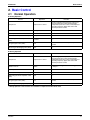
Basic Control
2. Basic Control
2.1
Normal Operation
Cooling Operation
Actuator
Operation
Remarks
Compressor
Compressor PI control
Used for high pressure protection control, low
pressure protection control, discharge pipe
temperature protection control, and compressor
operating frequency upper limit control with
inverter protection control.
Outdoor unit fan
Cooling fan control
Four way valve
OFF
Main electronic expansion valve (EV1)
1400 pls
Subcooling electronic expansion valve
(EV2)
PI control
Hot gas bypass valve (SVP)
OFF
This valve turns on with low pressure protection
control.
Receiver gas discharging valve (SVG)
OFF
—
Heating Operation
Actuator
Operation
Remarks
Compressor
Compressor PI control
Used for high pressure protection control, low
pressure protection control, discharge pipe
temperature protection control, and compressor
operating frequency upper limit control with
inverter protection control.
Outdoor unit fan
STEP8
The fan step changes to STEP1 with high pressure
> 454 psi.
Four way valve
ON
Main electronic expansion valve (EV1)
PI control
Subcooling electronic expansion valve
(EV2)
0 pls
Hot gas bypass valve (SVP)
OFF
This valve turns on with low pressure protection
control.
Receiver gas discharging valve (SVG)
OFF
—
∗ Heating operation is not functional at an outdoor air temperature of 86°FDB or more.
Function
21
Basic Control
2.2
SiUS25-501
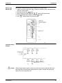
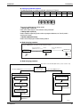
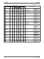
Compressor PI Control
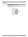
Compressor PI Control
Carries out the compressor capacity PI control to maintain Te at constant during cooling
operation and Tc at constant during heating operation to ensure stable unit performance.
[Cooling operation]
Controls compressor capacity to adjust Te to
achieve target value (TeS).
Te : Low pressure equivalent saturation temperature
(°F)
Te setting (Set in Set-up mode 2)
L
M (Normal)
H
(factory
setting)
TeS : Target Te value
(Varies depending on Te setting, operating
frequency, etc.)
37.5
43
48
[Heating operation]
Controls compressor capacity to adjust Tc to
achieve target value (TcS).
Tc setting
L
109.5
M (Normal)
(factory
setting)
115
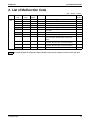
RZQ24 · 30 · 36 · 42M
STEP
1
2
3
4
5
6
7
8
9
10
11
12
13
14
15
16
17
H
Tc : High pressure equivalent saturation temperature
(°F)
TcS : Target Tc value
(Varies depending on Tc setting, operating
frequency, etc.)
120
INV
52Hz
57Hz
62Hz
68Hz
74Hz
81Hz
88Hz
96Hz
104Hz
110Hz
116Hz
124Hz
133Hz
143Hz
158Hz
165Hz
177Hz
∗ Compressors may operate in a pattern other than those listed
in above tables subject to the operating conditions.
22
Function
SiUS25-501
2.3
Basic Control
Electronic Expansion Valve PI Control
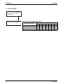
Main Electronic Expansion Valve EV1 Control
Carries out the electronic expansion valve (Y1E) PI control to maintain the evaporator outlet
superheated degree (SH) at constant during heating operation to make maximum use of the
outdoor unit heat exchanger (evaporator).
SH = Ts - Te
SH : Evaporator outlet superheated degree (°F)
Ts : Suction pipe temperature detected by thermistor
R2T (°F)
Te : Low pressure equivalent saturation temperature
(°F)
The optimum initial value of the evaporator outlet superheated degree is 5°C, but varies
depending on the discharge pipe superheated degree of inverter compressor.
Subcooling Electronic Expansion Valve EV2 Control
Makes PI control of the electronic expansion valve (Y2E) to keep the superheated degree (SH)
of the outlet gas pipe on the evaporator side for the full use of the subcooling heat exchanger.
SH = Tsh -Te
SH : Outlet superheated degree of evaporator (°F)
Tsh : Suction pipe temperature detected with the
thermistor R5T (°F)
Te : Low pressure equivalent saturation
temperature (°F)
Function
23
Basic Control
2.4
SiUS25-501
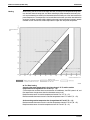
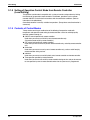
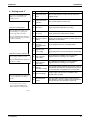
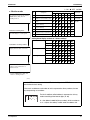
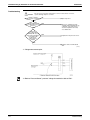
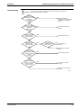
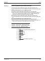
Cooling Operation Fan Control
In cooling operation with low outdoor air temperature, this control is used to provide the
adequate amount of circulation air with liquid pressure secured by high pressure control using
outdoor unit fan.
Pc>450 psi
Pc: HP pressure sensor detection value
STEP8
Pc<261 psi
Pc>348 psi
STEP7
Pc<261 psi
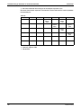
Fan Steps
Cooling
M1F
M2F
STEP0
0 rpm
0 rpm
STEP1
250 rpm
0 rpm
STEP2
400 rpm
0 rpm
STEP3
285 rpm
250 rpm
STEP4
360 rpm
325 rpm
STEP5
445 rpm
410 rpm
STEP6
580 rpm
545 rpm
STEP7
715 rpm
680 rpm
STEP8
850 rpm
815 rpm
Heating
M1F
M2F
STEP1
250rpm
0 rpm
STEP8
850 rpm
815rpm
Pc>348 psi
STEP6
Pc<261 psi
Pc>348 psi
STEP5
Pc<261 psi
Pc>348 psi
STEP4
Reference
Pc<261 psi
Pc>348 psi
STEP3
Pc<261 psi
Pc>334 psi
There are 2 steps in heating operation.
STEP2
Pc<261 psi
Pc>305 psi
STEP1
Pc<261 psi
Pc>276 psi
STEP0
(V3172)
24
Function
SiUS25-501
Special Control
3. Special Control
3.1
Startup Control
On activation, following control is performed to lighten load of the compressor by back liquid and
the like. Also, the position of the four way valve is defined.
3.1.1 Startup Control in Cooling Operation
Actuator
Operation
Compressor
Differential pressure control
Outdoor unit fan
High pressure control
Four way valve
Main electronic expansion valve (EV1)
Subcooling electronic expansion valve
(EV2)
Hot gas bypass valve (SVP)
Receiver gas discharging valve (SVG)
OFF
1400 pls
Remarks
Compressor operating frequency
increases by 2 step / 20 sec. until
Pc - Pe>58 psi.
Initial fan speed is set to STEP 0.
1-step increase with Pc>305 psi
1-step decrease with Pc<261 psi
0 pls
ON
OFF
Ending conditions
or
• 230 sec.
• Pc - Pe>58 psi
&( • 45 sec.
3.1.2 Startup Control in Heating Operation
Actuator
Compressor
Differential pressure control
Outdoor unit fan
Four way valve
Main electronic expansion valve (EV1)
Subcooling electronic expansion valve
(EV2)
Hot gas bypass valve (SVP)
Receiver gas discharging valve (SVG)
STEP8
ON
180 pls
Remarks
Compressor operating frequency
increases by 2 step / 20 sec. until
Pc - Pe>58 psi
0 pls
ON
OFF
Ending conditions
or
Function
Operation
• 145 sec.
• Pc - Pe>58 psi
&( • 15 sec.
25
Special Control
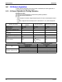
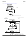
3.2
SiUS25-501
Oil Return Operation
Oil flown from the compressor to the side of system is collected by oil-returning operation, in
case of that oil in the compressor runs down.
3.2.1 Oil Return Operation in Cooling Operation
[Conditions to start]
The cooling oil-returning operation is started referring following conditions.
Integrated amount of displaced oil
Timer
(After the power is turned on, integrated operating-time is 2 hours and subsequently every 8
hours.)
In addition, integrated amount of displaced oil is derived from Tc, Te, and the compressor
load.
Outdoor unit actuator
Compressor
Outdoor unit fan
Four way valve
Main electronic expansion valve
(EV1)
Subcooling electronic expansion
valve (EV2)
Hot gas bypass valve (SVP)
Receiver gas discharging valve
(SVG)
Ending conditions
Oil return preparation
operation
Upper limit control
Fan control
OFF
124 Hz
Fan control
OFF
124 Hz
Fan control
OFF
1400 pls
1400 pls
1400 pls
SH control
0 pls
0 pls
OFF
ON
ON
OFF
OFF
OFF
20 sec.
or
Indoor unit actuator
Thermostat ON unit
Fan
Stopping unit
Thermostat OFF unit
Thermostat ON unit
Electronic expansion valve
Stopping unit
Thermostat OFF unit
26
Oil return operation
• 6 min.
• Ts - Te<5
Post-oil-return operation
3 min.
Cooling oil return operation
Set Air Volume
OFF
OFF
Normal opening
200 pls
200 pls
Function
SiUS25-501
Special Control
3.2.2 Oil Return Operation in Heating Operation
[Conditions to start]
The heating oil-returning operation is started referring following conditions.
Integrated amount of displaced oil
Timer
(After the power is turned on, integrated operating-time is 2 hours and subsequently every 8
hours.)
In addition, integrated amount of displaced oil is derived from Tc, Te, and the compressor
load.
Outdoor Unit Actuator
Oil return preparation
operation
Oil return operation
Post-oil-return operation
Compressor
Upper limit control
124 Hz
2-step increase from
52 Hz to
(Pc - Pe>58 psi) time
Outdoor unit fan
STEP8
OFF
STEP8
Four way valve
ON
OFF
ON
Main electronic expansion valve
(EV1)
SH control
1400 pls
200~400 pls
Subcooling electronic expansion
valve (EV2)
0 pls
0 pls
0 pls
Hot gas bypass valve (SVP)
OFF
ON
ON
Receiver gas discharging valve
(SVG)
ON
ON
OFF
Ending conditions
130 sec.
or
• 6 min.
• Ts - Te<5
or
• 160 sec.
• Pc - Pe>58 psi
* From the preparing oil-returning operation to the oil-returning operation, and from the oilreturning operation to the operation after oil-returning, the compressor stops for 1 minute to
reduce noise on changing of the four way valve.
Indoor unit actuator
Thermostat ON unit
Fan
Stopping unit
Thermostat OFF unit
Thermostat ON unit
Electronic expansion valve
Stopping unit
Thermostat OFF unit
Function
Heating oil return operation
OFF
OFF
OFF
500 pls
500 pls
500 pls
27
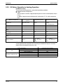
Special Control
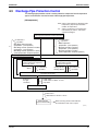
3.3
SiUS25-501
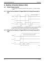
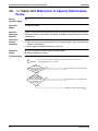
Defrosting Operation
The defrost operation is performed to solve frost on the outdoor unit heat exchanger when
heating, and the heating capacity is recovered.
[Conditions to start]
The defrost operation is started referring following conditions.
Outdoor heat exchanger heat transfer co-efficiency
Temperature of heat-exchange (Tb)
Timer (2 hours at the minimum)
In addition, outdoor heat-exchange co-efficiency is derived from Tc, Te, and the compressor
load.
Defrost preparation
operation
Outdoor unit actuator
Defrost operation
Post Defrost operation
Compressor
52 Hz
177 Hz
2-step increase from
52 Hz to
(Pc - Pe>58 psi)
every 20 sec.
Outdoor unit fan
STEP8
OFF
STEP8
Four way valve
ON
OFF
ON
Main electronic expansion valve
(EV1)
SH control
1400 pls
200~400 pls
Subcooling electronic expansion
valve (EV2)
0 pls
0 pls
0 pls
Hot gas bypass valve (SVP)
OFF
ON
ON
Receiver gas discharging valve
(SVG)
ON
ON
OFF
Ending conditions
130 sec.
or
• 15 min.
• Tb >51.8°F
or
• 160 sec.
• Pc - Pe>58 psi
* From the preparing operation to the defrost operation, and from the defrost operation to the
operation after defrost, the compressor stops for 1 minute to reduce noise on changing of the
four way valve.
Indoor unit actuator
Thermostat ON unit
Fan
Stopping unit
Thermostat OFF unit
Thermostat ON unit
Electronic expansion valve
Stopping unit
Thermostat OFF unit
28
During defrost
OFF
OFF
OFF
500 pls
500 pls
500 pls
Function
SiUS25-501
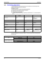
3.4
Special Control
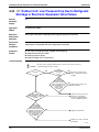
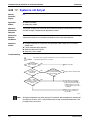
Pump-down Residual Operation
When activating compressor, if the liquid refrigerant remains in the heat-exchanger, the liquid
enters into the compressor and dilutes oil therein resulting in decrease of lubricity.
Therefore, the pump-down residual operation is performed to collect the refrigerant in the heatexchanger when the compressor is down.
3.4.1 Pump-down Residual Operation in Cooling Operation
Actuator
Compressor
Master unit operation
124 Hz
Outdoor unit fan
Fan control
Four way valve
OFF
Main electronic expansion valve (EV1)
2000 pls
Subcooling electronic expansion valve (EV2)
0 pls
Hot gas bypass valve (SVP)
OFF
Receiver gas discharging valve (SVG)
ON → OFF
Ending conditions
or
• 30 sec.
• Pe<73 psi
• Td>230°F
3.4.2 Pump-down Residual Operation in Heating Operation
Actuator
Master unit operation
Compressor
124 Hz
Outdoor unit fan
STEP8
Four way valve
ON
Main electronic expansion valve (EV1)
0 pls
Subcooling electronic expansion valve (EV2)
0 pls
Hot gas bypass valve (SVP)
OFF
Receiver gas discharging valve (SVG)
ON → OFF
Ending conditions
or
Function
• 3 min.
• Pe<36 psi
• Td>230°F
29
Special Control
3.5
SiUS25-501
Restart Standby
Restart is stood by force to prevent frequent power-on/off and to equalize pressure in the
refrigerant system.
Actuator
Operation
Remarks
Compressor
OFF
Outdoor unit fan
Ta>86°F: STEP4
Ta≤86°F: OFF
Four way valve
Keep former condition.
Main electronic expansion valve (EV1)
0 pls
Subcooling electronic expansion valve (EV2)
0 pls
Hot gas bypass valve (SVP)
ON
Receiver gas discharging valve (SVG)
OFF
Ending conditions
5 min.
30
Function
SiUS25-501
3.6
Special Control
Stopping Operation
Operation of the actuator when the system is down, is cleared up.
3.6.1 When System is in Stop Mode
Actuator
Operation
Compressor
OFF
Outdoor unit fan
OFF
Four way valve
Keep former condition.
Main electronic expansion valve (EV1)
0 pls
Subcooling electronic expansion valve (EV2)
0 pls
Hot gas bypass valve (SVP)
OFF
Receiver gas discharging valve (SVG)
OFF
Ending conditions
Indoor unit thermostat is turned ON.
Function
31
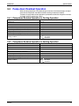
Special Control
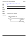
3.7
SiUS25-501
Pressure Equalization Prior to Startup
Before activating the compressor, the activation load is lightened by equalization across the
compressor. In addition, inverters turn on electricity and capacitors are charged.
Actuator
Operation
Remarks
Compressor
OFF
Outdoor unit fan
Cooling:OFF
Heating:Ta>78.8°F; STEP8,
Ta≤78.8°F; OFF
Four way valve
Keep former condition.
Main electronic expansion valve (EV1)
0 pls
Subcooling electronic expansion valve (EV2)
0 pls
Hot gas bypass valve (SVP)
ON
Receiver gas discharging valve (SVG)
OFF
Ending conditions
32
or
• • 3 min.
• • Pc-Pe<29 psi
Function
SiUS25-501
Protection Control
4. Protection Control
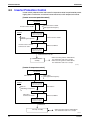
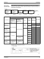
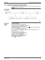
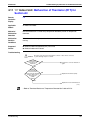
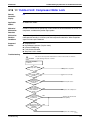
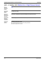
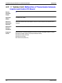
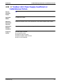
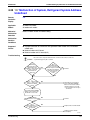
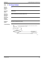
4.1
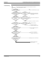
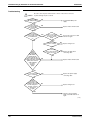
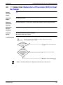
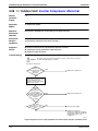
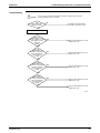
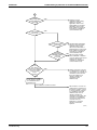
High Pressure Protection Control
This high pressure protection control is used to prevent the activation of protection devices due
to abnormal increase of high pressure and to protect compressors against the transient
increase of high pressure.
[In cooling operation]
Pc>493 psi
High pressure not limited
Pc: HP pressure sensor detection value
&
or
• INV upper limit frequency
• Pc ≤ 493 psi
• During oil return operation
• After oil return operation
• Stopping operation
• Heating operation
High pressure limited
INV upper limit frequency :
1-step down from current
compressor frequency
Every 10 sec.
Pc>500 psi
Keeping the current step
Pc<479 psi
479 psi≤Pc≤493 psi
Every 60 sec.
INV upper limit frequency:
1-step up from current
compressor frequency
Every
5 min.
INV upper limit frequency:
1-step up from current
compressor frequency
Pc>3.6MPa
When occurring 3 times within 30
minutes, HPS is activated without high
pressure standby, thus outputting the
malfunction code "E3".
High pressure
standby
(V3173)
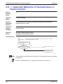
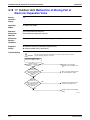
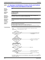
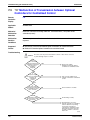
[In heating operation]
High-pressure drop
High pressure not limited
Pc>479 psi
Pc: HP pressure sensor detection value
Pc<450 psi
High pressure
limited
52Hz
Pc>522 psi
High pressure
standby
When HPS is activated, the
malfunction code "E3" is output.
(V3174)
Function
33
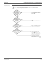
Protection Control
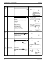
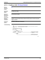
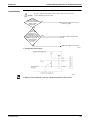
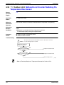
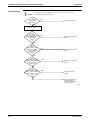
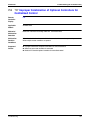
4.2
SiUS25-501
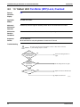
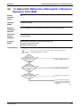
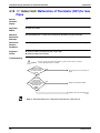
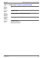
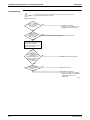
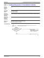
Low Pressure Protection Control
This low pressure protection control is used to protect compressors against the transient
decrease of low pressure.
[In cooling operation]
Low pressure not limited
Pe<36 psi
Pe: LP pressure sensor detection
value
Pe>58 psi
Low pressure
limited
52Hz
Pe<10 psi
Low pressure
standby
When occurring 3 times within 60 min.,
the malfunction code "E4" is output.
(V3175)
[In heating operation]
Pe: LP pressure sensor detection
value
• Pe>36 psi
& • INV upper limit
frequency
Low pressure not limited
Pe<23 psi
Low pressure limited
&
More than 124Hz
Pe<23 psi
Upper limit:
124Hz
Pe<19 psi
Pe<19 psi
Upper limit:
52Hz
Pe>28 psi
Upper limit: 1-step up from
current compressor frequency
Pe>28 psi (every 20 sec.)
Pe>25 psi
SVP = OFF
SVP = ON
Pe<15 psi
Pe<10 psi
Low pressure
standby
When occurring 3 times within 60 min.,
the malfunction code "E4" is output.
(V3176)
34
Function
SiUS25-501
4.3
Protection Control
Discharge Pipe Protection Control
This discharge pipe protection control is used to protect the compressor internal temperature
against a malfunction or transient increase of discharge pipe temperature.
[INV compressor]
HTdi :Value of INV compressor discharge pipe
temperature (Tdi) compensated with
outdoor air temperature
Tp : Value of compressor port temperature
calculated by Tc and Te, and suction
superheated degree.
Discharge pipe protection control not limited
&
or
• HTdi>221˚F
• Tp>266˚F
&
• Not during defrost operation
(preparation ~ post operation)
• Not during oil return operation in heating
(preparation ~ post operation)
• Not during oil return operation in cooling
(without preparation and post opeation)
or
• HTdi<203˚F
• Tp<212˚F
• Defrost operation
(preparation ~ post operation)
• Oil return operation in heating
(preparation ~ post operation)
• Oil return operation in cooling
(without preparation and post operation)
In discharge pipe protection control
INV upper limit frequency:
1-step up from current
compressor frequency
INV frequency 1-step down from
current compressor frequency
(lower limit: 52Hz)
30 sec.
or
• HTdi>230˚F
• Tp>266˚F
Cooling: 20 sec.
Heating: 60 sec.
&
• HTdi<212˚F
• Tp<239˚F
Keep the current step
Exclusion of
the right
conditions
or
• HTdi>266˚F
• HTdi>239˚F for 90sec. or more
• Tp>284˚F
Fix INV frequency 52Hz
or
HTdi>275˚F
HTdi>239˚F for 10 min. or more.
Discharge pipe
temp.control standby
When occurring 3 times within 100 min.,
the malfunction code "F3" is output.
(V3177)
Function
35
Protection Control
4.4
SiUS25-501
Inverter Protection Control
Inverter current protection control and inverter fin temperature control are performed to prevent
tripping due to a malfunction, or transient inverter overcurrent, and fin temperature increase.
[Inverter overcurrent protection control]
Not limited
&
Inverter current >23.8A
Limited
•Inverter current ≤ 23.8A
•INV upper limit frequency
INV upper limit frequency:
1-step down from current
compressor frequency
•10 sec.
& •Matching of frequency
Inverter current >23.8A
Status quo
Inverter current ≤ 23.8A
continues for 3 min.
Without conditions
INV upper limit frequency:
1-step up from current
compressor frequency
Inverter current ≥ 24.9A
• When occurring 3 times within 60 min.,
the malfunction code "L8 " is output.
• When occurring 3 times within 30 min.,
the malfunction code "L9" is output
Inverter current
standby
(V3178)
[Inverter fin temperature control]
Not limited
Tfin≥199.4˚F
Limited
&
&
•Tfin<194˚F
•INV upper limit frequency
INV upper limit frequency:
1-step down from current
compressor frequency
Tfin≥199.4˚F
•10 sec.
•Macthing of frequency
Status quo
Tfin≤194˚F
continues for 3 min.
Without conditions
INV upper limit frequency:
1-step up from current
compressor frequency
Tfin≥210˚F
Fin temp. standby
• When occurring 3 times within 60 min.,
the malfunction code "L4" is output.
(V3179)
36
Function
SiUS25-501
Other Control
5. Other Control
5.1
Heating Operation Prohibition
Heating operation is prohibited above 86°FDB outdoor air temperature.
Function
37
Outline of Control (Indoor Unit)
SiUS25-501
6. Outline of Control (Indoor Unit)
6.1
Drain Pump Control
1. The drain pump is controlled by the ON/OFF buttons (4 button (1) - (4) given in the figure
below).
6.1.1 When the Float Switch is Tripped While the Cooling Thermostat is
ON:
∗ 1. The objective of residual operation is to completely drain any moisture adhering to the fin of
the indoor unit heat exchanger when the thermostat goes off during cooling operation.
6.1.2 When the Float Switch is Tripped While the Cooling Thermostat is
OFF:
38
Function
SiUS25-501
Outline of Control (Indoor Unit)
6.1.3 When the Float Switch is Tripped During Heating Operation:
During heating operation, if the float switch is not reset even after the 5 minutes operation, 5
seconds stop, 5 minutes operation cycle ends, operation continues until the switch is reset.
6.1.4 When the Float Switch is Tripped and “AF” is Displayed on the
Remote Controller:
Note:
Function
If the float switch is tripped five times in succession, a drain malfunction is determined to have
occurred. “AF” is then displayed as operation continues.
39
Outline of Control (Indoor Unit)
6.2
SiUS25-501
Louver Control for Preventing Ceiling Dirt
We have added a control feature that allows you to select the range of in which air direction can
be adjusted in order to prevent the ceiling surrounding the air discharge outlet of ceiling
mounted cassette type units from being soiled.
Existing position
P0
P1
P2
P3
P4
Ceiling soiling prevention
position
Standard Setting
position
Draft prevention position
(Not for Multi flow type)
P0
P0
P1
P1
P3
P4
P4
P1
P2
P4
P3'
P4'
P0
P2
P0'
P1'
P2'
P2
Draft
prevention
position
P0
P3
P4
P0''
P1''
P2''
P3''
P4''
Same as existing position
Range of direction adjustment
Standard
position
Prohibited
P0'
P1'
P2'
P3'
P4'
Separated into 5 positions
(P1 - 4)
Range of direction adjustment
Dirt
prevention
position
Prohibited
P0''
P1''
P2''
P3''
P4''
Separated into 5 positions
(P2 - 4)
(VL012)
The factory set position is standard position.
40
Function
SiUS25-501
6.3
Outline of Control (Indoor Unit)
Thermostat Sensor in Remote Controller
Temperature is controlled by both the thermostat sensor in remote controller and air suction
thermostat in the indoor unit. (This is however limited to when the field setting for the thermostat
sensor in remote controller is set to “Use.”)
Note:
Cooling
When OA (outdoor air) is introduced to the air-conditioner with mixed into indoor air, the room
temperature may fail to be preset temperature, since TS and TH1 do not enter the area of “use
range of remote control thermostat.” In such a case, put the remote sensor (optional accessory)
in your room, and use it with setting “do not use remote control thermostat.”
If there is a significant difference in the preset temperature and the suction temperature, fine
adjustment control is carried out using a body thermostat sensor, or using the sensor in the
remote controller near the position of the user when the suction temperature is near the preset
temperature.
Ex: When cooling
Assuming the preset temperature in the figure above is 75°F, and the suction
temperature has changed from 64°F to 86°F (A → F):
(This example also assumes there are several other air conditioners, the VRV system is off, and
that temperature changes even when the thermostat sensor is off.)
Body thermostat sensor is used for temperatures from 64°F to 73°F (A → C).
Remote controller thermostat sensor is used for temperatures from 73°F to 81°F (C → E).
Body thermostat sensor is used for temperatures from 81°F to 86°F (E → F).
And, assuming suction temperature has changed from 86°F to 64°F (F → A):
Body thermostat sensor is used for temperatures from 86°F to 77°F (F → D).
Remote controller thermostat sensor is used for temperatures from 77°F to 70°F (D → B).
Body thermostat sensor is used for temperatures from 70°F to 64°F (B → A).
Function
41
Outline of Control (Indoor Unit)
Heating
SiUS25-501
When heating, the hot air rises to the top of the room, resulting in the temperature being lower
near the floor where the occupants are. When controlling by body thermostat sensor only, the
unit may therefore be turned off by the thermostat before the lower part of the room reaches the
preset temperature. The temperature can be controlled so the lower part of the room where the
occupants are doesn’t become cold by widening the range in which thermostat sensor in remote
controller can be used so that suction temperature is higher than the preset temperature.
Ex: When heating
Assuming the preset temperature in the figure above is 75°F, and the suction
temperature has changed from 64°F to 82°F (A → D):
(This example also assumes there are several other air conditioners, the VRV system is off, and
that temperature changes even when the thermostat sensor is off.)
Body thermostat sensor is used for temperatures from 64°F to 77°F (A → C).
Remote controller thermostat sensor is used for temperatures from 77°F to 82°F (C → D).
And, assuming suction temperature has changed from 82°F to 64°F (D → A):
Remote controller thermostat sensor is used for temperatures from 82°F to 73°F (D → B).
Body thermostat sensor is used for temperatures from 73°F to 64°F (B → A).
42
Function
SiUS25-501
6.4
Outline of Control (Indoor Unit)
Freeze Prevention
Freeze
Prevention by Off
Cycle (Indoor
Unit)
When the temperature detected by liquid pipe temperature thermistor (R2T) of the indoor unit
heat exchanger drops too low, the unit enters freeze prevention operation in accordance with
the following conditions, and is also set in accordance with the conditions given below.
Conditions for starting freeze prevention: Temperature is 30°F or less for total of 40 min., or
temperature is 23°F or less for total of 10 min.
Conditions for stopping freeze prevention: Temperature is 45°F or more for 10 min.
continuously.
Ex: Case where temperature is 23°F or less for total of 10 min.
Function
43
Outline of Control (Indoor Unit)
6.5
SiUS25-501
View of Operations of Swing Flaps
Swing flaps work as following.
Fan
Swinging
OFF
Setting the wind direction
Swinging
OFF
OFF
Level
Level
Level
Level
Setting the wind direction
Swinging
OFF
LL
Level
Level
Level
Level
Setting the wind direction
Swinging
LL
LL
Level
Level
Level
Level
Setting the wind direction
LL
Level
Level
Swinging
Setting the wind direction
OFF
OFF
Level
Level
Level
Level
Swinging
L*1
Swinging
Swinging
Setting the wind direction
L*1
Set up
Set up
Swinging
Swinging
Setting the wind direction
OFF
or
L
Set up
Set up
Cooling thermostat
is off
Swinging
Setting the wind direction
Set up
Set up
Swinging
Set up
Swinging
Set up
Halt
Swinging
Setting the wind direction
OFF
OFF
Level
Set up
Level
Level
L
Swinging
Swinging
L
Set up
Set up
Hot-start from
defrosting
Heating
Defrosting
Thermostat is off
Hot-start from the
state that the
thermostat is off
Halt
Cooling
Flap control
FCQ
Level
Thermostat of
microcomputer-dry
is on
Thermostat of
microcomputer-dry
is off
Swinging
Microcomputer is
Swinging
controlled (including
Setting the wind direction
the cooling state)
FHQ
Level
* 1. Only in FCQ case, L or LL.
44
Function
SiUS25-501
Part 6
Test Operation
1. Test Operation ......................................................................................46
1.1 Procedure and Outline ........................................................................... 46
1.2 Operation When Power is Turned On .................................................... 49
2. Outdoor Unit PC Board Layout .............................................................50
3. Field Setting ..........................................................................................51
3.1 Field Setting from Remote Controller..................................................... 51
3.2 Field Setting from Outdoor Unit ............................................................. 62
3.3 Detail of Setting Mode............................................................................ 68
Test Operation
45
Test Operation
SiUS25-501
1. Test Operation
1.1
Procedure and Outline
Follow the following procedure to conduct the initial test operation after installation.
1.1.1 Check Work Prior to Turn Power Supply On
Check the below items.
2Power wiring
2Control transmission wiring
between units
2Earth wire
¡ Is the power supply single-phase 208-230V / 60Hz?
¡ Have you finished a ductwork to drain?
¡ Have you detach transport fitting?
¡ Is the wiring performed as specified?
¡ Are the designated wires used?
¡ Is the grounding work completed?
¡
¡
Check on refrigerant piping
¡ Is pipe size proper? (The design pressure of this product is
580 psi.)
¡ Are pipe insulation materials installed securely?
¡
Check on amount of refrigerant
charge
Use a 500V megger tester to measure the insulation.
2 Do not use a megger tester for other circuits than 200-230V circuit.
Are the setscrews of wiring not loose?
Is the electrical component box covered with an insulation cover
completely?
Liquid and gas pipes need to be insulated. (Otherwise causes
water leak.)
Are respective stop valves on liquid and gas line securely open?
¡ Is refrigerant charged up to the specified amount?
¡
If insufficient, charge the refrigerant from the service port of stop
valve on the liquid side with outdoor unit in stop mode after turning
power on.
Has the amount of refrigerant charge been recorded on “Record
Chart of Additional Refrigerant Charge Amount”?
(V3180)
1.1.2 Turn Power On
Turn outdoor unit power on.
¡ Be sure to turn the power on 6 hours before starting operation to
protect compressors.
¡ Close outside panels of the outdoor unit.
Turn indoor unit power on.
Carry out field setting on
outdoor PC board
(V3056)
46
Test Operation
SiUS25-501
Test Operation
1.1.3 Check Operation
* During check operation, mount front panel to avoid the misjudging.
* Check operation is mandatory for normal unit operation.
(When the check operation is not executed, alarm code "U3" will be displayed.)
Press and hold the TEST
button (BS4) on outdoor unit
PC board for 5 seconds.
Check on operation
¡ The test operation is started automatically.
The following judgements are conducted within 15 minutes(about 30
at the maximum).
minutes
2“Check for wrong wiring”
2“Check stop valve for not open”
2“Pipe length automatic judgement”
The following indications are conducted while in test operation.
2LED lamp on outdoor unit PC board H2P flickers (test operation)
2Remote controller Indicates “Under Centralized Control” on
upper right.
Indicates “Test Operation” on lower left
(V3057)
On completion of test operation, LED on outdoor unit PC board displays the following.
H3P ON: Normal completion
H2P and H3P ON: Abnormal completion → Check the indoor unit remote controller for
abnormal display and correct it.
H1PH2PH3PH4PH5PH6PH7P
(For normal completion)
1 1 8 1 1 1 1
(For abnormal completion) 1 8 8 1 1 1 1
Malfunction code
In case of an alarm code displayed on remote controller:
Malfunction
code
E3
Nonconformity during installation
The shutoff valves in the outdoor unit
remain closed.
Open the shutoff valve on both the gas side and liquid side.
The refrigerant is overcharged.
Calculate again the required quantity of refrigerant to be charged
based on the piping length, recover the refrigerant using the
refrigerant recovery device, then achieve proper quantity of
refrigerant.
Open the shutoff valve on both the gas side and liquid side.
The shutoff valves in the outdoor unit
remain closed.
E4
F3
Remedial action
The operation mode on the remote controller Set the operating mode on all indoor unit remote controllers to
was changed before the check run.
“cooling”.
The refrigerant is insufficient.
The refrigerant is overcharged.
F6
• Check whether additional refrigerant charge has been finished
correctly.
• Calculate again the required quantity of refrigerant to be
charged based on the piping length, then charge additionally
proper quantity of refrigerant.
Calculate again the required quantity of refrigerant to be charged
based on the piping length, recover the refrigerant using the
refrigerant recovery device, then achieve proper quantity of
refrigerant.
U3
U4
The check operation is not performed.
Perform the check operation.
The power is not supplied to the outdoor unit. Connect correctly the power cable of the outdoor unit.
UA
Improper type of indoor units are
connected.
Test Operation
Check the type of indoor units currently connected. If they are not
proper, replace them with proper ones.
47
Test Operation
UF
UH
SiUS25-501
The shutoff valves in the outdoor unit
remain closed.
The piping and wiring of the specified indoor
unit are not connected correctly to the
outdoor unit.
The operation mode on the remote
controller was changed before the check
run.
The unit-to-unit wirings are not connected
correctly.
Open the shutoff valve on both the gas side and liquid side.
Confirm that the piping and wiring of the specified indoor unit are
connected correctly to the outdoor unit.
Set the operating mode on all indoor unit remote controllers to
“cooling”.
Connect correctly the unit-to-unit wirings to the F1 and F2(TO IN/
D UNIT) terminals on the PC board (A1P) in the outdoor unit.
1.1.4 Confirmation on Normal Operation
• Conduct normal unit operation after the check operation has been completed.
(When outdoor air temperature is 86°FDB or higher, the unit can not be operated with
heating mode. See the installation manual attached.)
• Confirm that the indoor/outdoor units can be operated normally.
(When an abnormal noise due to liquid compression by the compressor can be heard, stop
the unit immediately, and turn on the crankcase heater to heat up it sufficiently, then start
operation again.)
• Operate indoor unit one by one to check that the corresponding outdoor unit operates.
• Confirm that the indoor unit discharges cold air (or warm air).
• Operate the air direction control button and flow rate control button to check the function of
the devices.
48
Test Operation
SiUS25-501
1.2
Test Operation
Operation When Power is Turned On
1.2.1 When Turning On Power First Time
The unit cannot be run for up to 12 minutes to automatically set the master power and address
(indoor-outdoor address, etc.).
Status
Outdoor unit
Test lamp H2P .... Blinks
Can also be set during operation described above.
Indoor unit
If ON button is pushed during operation described above, the “UH”
malfunction indicator blinks.
(Returns to normal when automatic setting is complete.)
1.2.2 When Turning On Power the Second Time and Subsequent
Tap the RESET(BS5) button on the outdoor unit PC board. Operation becomes possible for
about 2 minutes. If you do not push the RESET button, the unit cannot be run for up to 10
minutes to automatically set master power.
Status
Outdoor unit
Test lamp H2P .... Blinks
Can also be set during operation described above.
Indoor unit
If ON button is pushed during operation described above, the operation lamp
lights but the compressor does not operate. (Returns to normal when
automatic setting is complete.)
1.2.3 When an Indoor Unit or Outdoor Unit Has Been Added, or Indoor or
Outdoor Unit PC Board Has Been Changed
Be sure to push and hold the RESET button for 5 seconds. If not, the addition cannot be
recognized. In this case, the unit cannot be run for up to 12 minutes to automatically set the
address (indoor-outdoor address, etc.)
Status
Outdoor unit
Test lamp H2P .... ON
Can also be set during operation described above.
Indoor unit
Test Operation
If ON button is pushed during operation described above, the “UH” or “U4”
malfunction indicator blinks. (Returns to normal when automatic setting is
complete.)
49
Outdoor Unit PC Board Layout
SiUS25-501
2. Outdoor Unit PC Board Layout
Outdoor unit PC board
DEMAND
SLAVE
MASTER
IND
L.N.O.P
C/H
SELECTOR
TEST:9
HWL:8
(3) Mode setting switch
MODE
(2) Set mode display (LED)
H1P H2P H3P H4P H5P H6P H7P
BS1
BS2
BS3
BS4
BS5
MODE
SET
RETURN
TEST
RESET
(1) Service monitor
HAP
1 2 3 4 1 2 3 4
DS1
DS2
(4) Local setting switch
Connection terminal for transmission use
A
B
C F1 F2 F1 F2
C/H SELECTOR
TO IN / D
UNIT
TO OUT / D
UNIT
(V3171)
(1) Service monitor (LED Green)
This monitor blinks while in normal operation, and turns on or off when a malfunction occurs.
(2) Set mode display (LED Orange)
LEDs display mode according to the setting.
(3) Mode setting switch
Used to change mode.
(4) Local setting switch
Used to make local settings.
50
Test Operation
SiUS25-501
Field Setting
3. Field Setting
3.1
Field Setting from Remote Controller
Individual function of indoor unit can be changed from the remote controller. At the time of
installation or after service inspection / repair, make the local setting in accordance with the
following description.
Wrong setting may cause malfunction.
(When optional accessory is mounted on the indoor unit, setting for the indoor unit may be
required to change. Refer to information in the option handbook.)
3.1.1 Wired Remote Controller <BRC1C71>
If optional accessories are mounted on the indoor unit, the indoor unit setting may have to be
changed. Refer to the instruction manual for each optional accessory.
UNIT NO.
MODE NO.
SECOND
CODE NO.
Unit NO.
FIELD
SET
MODE
SETTIING
3
FIRST
CODE NO.
1 7
4
TEST
6
5
2
2P068938
1. When in the normal mode, press the “
” button for a minimum of four seconds, and the
FIELD SET MODE is entered.
2. Select the desired MODE NO. with the “
” button (�).
3. During group control, when setting by each indoor unit (mode No. 20, 21 and 23 have been
selected), push the “
” button (�) and select the INDOOR UNIT NO to be set. (This
operation is unnecessary when setting by group.)
4. Push the “
” upper button (�) and select FIRST CODE NO.
5. Push the “
” lower button (�) and select the SECOND CODE NO.
6. Push the “
” button (�) once and the present settings are SET.
7. Push the “
” button (�) for about one second to return to the NORMAL MODE.
(Example)
If during group setting and the time to clean air filter is set to FILTER CONTAMINATION,
HEAVY, SET MODE NO. to “10” FIRST CODE NO. to “0,” and SECOND CODE NO. to “02.”
Test Operation
51
Field Setting
SiUS25-501
3.1.2 Wireless Remote Controller - Indoor Unit
BRC7C812
BRC7E83
1. When in the normal mode, push the
button for 4 seconds or more, and operation
then enters the “field set mode.”
2. Select the desired “mode No.” with the
button.
3. Pushing the
button, select the first code No.
4. Pushing the
button, select the second code No.
5. Push the timer
button and check the settings.
6. Push the
button to return to the normal mode.
(Example)
When setting the filter sign time to “Filter Dirtiness-High” in all group unit setting, set the Mode
No. to “10”, Mode setting No. to “0” and setting position No. to “02”.
52
Test Operation
SiUS25-501
Field Setting
3.1.3 Simplified Remote Controller
BRC2A71
6
13
2
1
3
5
H L
F
7
4
8
9
11
10
12
BRC2A71
REMOTE CONTROLLER: NAME AND FUNCTION OF EACH SWITCH AND DISPLAY
DISPLAY “
CONTROL)
ON/OFF BUTTON
�
�
Press the button and the system will start. Press the
button again and the system will stop.
OPERATION LAMP (RED)
�
The lamp lights up during operation. Blinks in case of stop
due to malfunction.
DISPLAY “
CONTROL)
�
” (CHANGEOVER UNDER
It is impossible to changeover heating/cooling with the
remote controller when it shows this display. (As for details,
see “SETTING OF MASTER REMOTE CONTROLLER” in
the installation manual attached to the indoor unit.)
DISPLAY “
�
F
This display shows the set temperature. Only given during
a cooling or heating operation.
”“
”“
”
This display shows current OPERATION MODE.
“ ” is not available with outdoor units specially designed
for cooling only.
“
” is reserved only for outdoor units capable of heat
recovery.
L
” (FAN SPEED)
” (DEFROST / HOT START)
Indicates that defrost or hot start (during which the fan is
stopped till the temperature of air supply rises enough at
the start of a heating operation) is in progress.
TEMPERATURE SETTING BUTTON
��
” (SET TEMPERATURE)
DISPLAY “ ” “ ” “
(OPERATION MODE)
�
�
H
This display shows the fan speed: HIGH or LOW.
DISPLAY “
” (VENTILATION/AIR
This display shows that the total heat exchanger and the
air cleaning unit are in operation. (These are optional
accessories).
DISPLAY “
�
When this display shows, the system is UNDER
CENTRALIZED CONTROL.
(This is not a standard specification)
DISPLAY “
�
” (UNDER CENTRALIZED
Use this button for SETTING TEMPERATURE of the
thermostat.
; Each press raises the set temperature by 1°F.
; Each press lowers the set temperature by 1°F.
The variable temperature range is between 60°F and 90°F.
FAN SPEED CONTROL BUTTON
��
��
Press this button to select the fan speed, HIGH or LOW,
of your choice.
OPERATION MODE SELECTOR BUTTON
Press this button to select OPERATION MODE.
DISPLAY “
��
” (MALFUNCTION)
Indicates malfunction and blinks if the unit stops operating
due to malfunction.
(As for details, see “TROUBLE SHOOTING” in the
operation manual attached to the outdoor unit.)
For the sake of explanation, all indications are shown in the figure above contrary to actual running situations.
3P146204
Test Operation
53
Field Setting
SiUS25-501
3.1.4 Setting Contents and Code No. – VRV Unit
Field Setting Contents and Code No.
0
10(20)
12(22)
Ultra-Long-Life
Type
Filter Contamination-Heavy/
Light (Setting for display time
to clean air filter) (Sets display
time to clean air filter to half
Long-Life Type
when there is heavy filter
contamination.)
Standard Type
1
Long-life filter type (Setting of filter sign indication
time) (Change setting when Ultra-long-life filter is
installed)
2
Thermostat Sensor in Remote Controller
3
Display Time to Clean Air Filter Calculation
(Set when filter sign is not to be displayed)
0
Optional accessories output selection
(field selection of output for adaptor for wiring)
1
01
02
Approx.
10,000
hours
Approx.
5,000
hours
Approx.
2,500
hours
Approx.
200 hours
Approx.
1,250
hours
03
04
—
—
Approx.
100 hours
Long-Life
Filter
Ultra-LongLife Filter
—
—
Use
Not Use
—
—
Display
Do not
Display
—
—
Indoor Unit
Turned ON by
Thermostat
—
Operation
Output
Malfunction
Output
ON/OFF Input from Outside (Set when ON/OFF is
to be controlled from outside.)
Forced Off
ON/OFF
Control
External
Protection
Device
Input
—
2
Thermostat Differential Changeover (Set when
remote sensor is to be used.)
FCQ only
2°F
1°F
—
—
5
Power failure automatic reset (Auto Restart)
No equipped
4
Field set air flow position setting
5
Field set fan speed selection (fan speed control by
air discharge outlet for phase control)
13(23)
Notes:
54
SECOND CODE NO. Note)3
Description of Setting
Heavy
FIRST
CODE No.
Light
Mode No.
Note)2
Equipped
—
—
Draft
Prevention
Standard
Ceiling Soiling
Prevention
—
Standard
Optional
Accessory 1
Optional
Accessory 2
—
1. Settings are made simultaneously for the entire group, however, if you select the mode No.
inside parentheses, you can also set by each individual unit. Setting changes however
cannot be checked except in the individual mode for those in parentheses.
2. The mode numbers inside parentheses cannot be used by wireless remote controllers, so
they cannot be set individually. Setting changes also cannot be checked.
3. Marked
are factory set.
4. Do not make settings other than those described above. Nothing is displayed for functions
the indoor unit is not equipped with.
5. “88” may be displayed to indicate the remote controller is resetting when returning to the
normal mode.
Test Operation
SiUS25-501
Field Setting
3.1.5 Applicable Range of Field Setting
Mode No.
10
(20)
12
(22)
13
(23)
Setting
Switch
No.
Ceiling mounted cassette type (Multi flow)
Ceiling suspended type
FCQ
FHQ
Setting Contents
0
Filter sign
{
{
1
Ultra long life filter sign
{
—
2
Remote controller
thermostat sensor
{
{
3
Set fan speed when
thermostat OFF
{
{
0
Air flow adjustment Ceiling
height
{
{
1
Air flow direction
{
—
3
Air flow direction
adjustment
(Down flow operation)
—
—
4
Air flow direction
adjustment range
{
—
5
Field set fan speed
selection
—
—
Test Operation
55
Field Setting
SiUS25-501
3.1.6 Detailed Explanation of Setting Modes
Filter Sign Setting
If switching the filter sign ON time, set as given in the table below.
Set Time
Filter Specs.
Mode No.
Setting
Contamination Light
Contamination Heavy
Setting
Switch No.
10(20)
0
Lighting interval of the filter sign
(hours)
Setting
Position
No.
Standard
01
200 hrs.
2,500 hrs.
Ultra Long
Life Filter
10,000 hrs.
02
100 hrs.
1,250 hrs.
5,000 hrs.
Long Life
Fan Speed Changeover When Thermostat is OFF
By setting to “Set Fan Speed,” you can switch the fan speed to the set fan speed when the
heating thermostat is OFF.
∗ Since there is concern about draft if using “fan speed up when thermostat is OFF,” you should
take the setup location into consideration.
On warming, the priority is given to this over "airflow OFFSW on thermostat off".
.This is used to correspond with the improvement of the electrical collection capability.
Setting Table
Mode No.
First Code No.
12(22)
3
Second Code No.
01
Setting
LL Fan Speed
02
Set Fan Speed
Auto Restart after Power Failure Reset
For the air conditioners with no setting for the function (same as factory setting), the units will be
left in the stop condition when the power supply is reset automatically after power failure reset
or the main power supply is turned on again after once turned off. However, for the air
conditioners with the setting, the units may start automatically after power failure reset or the
main power supply turned on again (return to the same operation condition as that of before
power failure).
For the above reasons, when the unit is set enabling to utilize “Auto restart function after power
failure reset”, utmost care should be paid for the occurrence of the following situation.
Caution 1. The air conditioner starts operation suddenly after power failure reset or
the main power supply turned on again. Consequently, the user might be
surprised (with question for the reason why).
2. In the service work, for example, turning off the main power switch during
the unit is in operation, and turning on the switch again after the work is
completed start the unit operation (the fan rotates).
56
Test Operation
SiUS25-501
Field Setting
Setting of Air Flow Direction Adjustment Range
Make the following air flow direction setting according to the respective purpose.
Setting Table
Mode No.
First Code No.
Second Code No.
01
Setting
Upward (Draft prevention)
13 (23)
4
02
Standard
Downward (Ceiling soiling
prevention)
03
Test Operation
57
Field Setting
SiUS25-501
3.1.7 Centralized Control Group No. Setting
BRC1C Type
If carrying out centralized control by central remote controller or unified ON/OFF
1.
2.
3.
4.
5.
6.
controller, group No. must be set for each group individually by remote controller.
Group No. setting by remote controller for centralized control
If the inspection/test button is pushed for 4 seconds or more when in the normal mode,
operation enters the “field set mode.”
Using the temperature control buttons, set the mode No. to “00.”
Push the inspection/test button to inspect the group No. display.
Using the programming time button, set the group No. for each group. (Group No. rises in
the order of 1-00, 1-01, ...1-15, 2-00 ...4-15, etc. The unified ON/OFF controller however
displays only the range of group numbers selected by the switch for setting each address.)
Push the timer ON/OFF button and enter the selected group No.
Push the inspection/test button and return to the normal mode.
* If the address has to be set individually for each unit for power consumption counting, etc., set
the mode No. to “30.”
58
Test Operation
SiUS25-501
Field Setting
BRC7C Type
BRC7E Type
Group No. setting by wireless remote controller for centralized control
1. When in the normal mode, push
button for 4 seconds or more, and operation then
enters the “field set mode.”
2. Set mode No. “00” with
button.
3. Set the group No. for each group with
button (advance/backward).
4. Enter the selected group numbers by pushing
button.
5. Push
button and return to the normal mode.
Group No. Setting
Example
Indoor unit
P1·P2
P1·P2
P1·P2
Central remote controller
Unified ON/OFF controller
Group No. for 1-00
centralized
control
P1·P2
1-01
1-02
P1·P2
P1·P2
P1·P2
No remote controller
Remote controller centralized control
(automatic address)
1-03
1-04
(V3170)
Caution
Test Operation
When turning the power supply on, the unit may often not accept any operation while "88" is
displaying after all indications were displayed once for about 1 minute on the liquid crystal
display. This is not an operative fault.
59
Field Setting
SiUS25-501
3.1.8 Setting of Operation Control Mode from Remote Controller
(Local Setting)
The operation control mode is compatible with a variety of controls and operations by limiting
the functions of the operation remote controller. Furthermore, operations such as remote
controller ON/OFF can be limited in accordance with the combination conditions. (Refer to
information in the table below.)
Centralized controller is normally available for operations. (Except when centralized monitor is
connected)
3.1.9 Contents of Control Modes
Twenty modes consisting of combinations of the following five operation modes with
temperature and operation mode setting by remote controller can be set and displayed by
operation modes 0 through 19.
ON/OFF control impossible by remote controller
Used when you want to turn on/off by central remote controller only.
(Cannot be turned on/off by remote controller.)
OFF control only possible by remote controller
Used when you want to turn on by central remote controller only, and off by remote controller
only.
Centralized
Used when you want to turn on by central remote controller only, and turn on/off freely by
remote controller during set time.
Individual
Used when you want to turn on/off by both central remote controller and remote controller.
Timer operation possible by remote controller
Used when you want to turn on/off by remote controller during set time and you do not want
to start operation by central remote controller when time of system start is programmed.
60
Test Operation
SiUS25-501
How to Select
Operation Mode
Example
ON by remote
controller
(Unified ON by
central remote
controller)
↓
Rejection
Field Setting
Whether operation by remote controller will be possible or not for turning on/off, controlling
temperature or setting operation mode is selected and decided by the operation mode given on
the right edge of the table below.
OFF by remote
controller
(Unified OFF by
central remote
controller)
OFF by
remote
controller
↓
Rejection
↓
Rejection
Temperature
control by
remote controller
Operation mode
setting by
remote controller
↓
Acceptance
↓
Acceptance
Control
mode is "1."
(VL069)
Control by remote controller
Operation
Control mode
Unified operation,
individual operation
by central remote
controller, or
operation controlled
by timer
Unified OFF,
individual stop by
central remote
controller, or timer
stop
OFF
Temperature
Operation
control
mode setting
Rejection
ON/OFF control
impossible by
remote controller
Rejection
(Example)
Acceptance
(Example)
Rejection (Example)
Rejection
OFF control only
possible by
remote controller
Rejection (Example)
Acceptance
Rejection
Centralized
Acceptance
Acceptance
Acceptance
Rejection
Individual
Acceptance
Acceptance
Timer operation
possible by
remote controller
Acceptance
(During timer at ON
position only)
Rejection
(During timer at OFF
position)
Rejection
Acceptance
Control mode
Acceptance
0
Rejection
Acceptance
(Example)
10
1(Example)
Rejection
Acceptance
11
2
Rejection
Acceptance
12
3
Rejection
Acceptance
13
4
Rejection
Acceptance
14
5
Rejection
Acceptance
15
6
Rejection
Acceptance
16
7 ∗1
Rejection
Acceptance
17
8
Rejection
Acceptance
18
9
Rejection
19
Do not select “timer operation possible by remote controller” if not using a remote controller.
Operation by timer is impossible in this case.
∗1. Factory setting
Test Operation
61
Field Setting
3.2
SiUS25-501
Field Setting from Outdoor Unit
3.2.1 Setting by dip switches
The following field settings are made by dip switches on PC board.
Dipswitch
Setting
Setting item
ON
OFF (Factory set)
Cool / Heat
change over
setting
Do not change the factory setting.
ON
DS1-2
~DS1-4 OFF (Factory set)
Not used
Do not change the factory settings.
ON
OFF (Factory set)
Not used
Do not change the factory settings.
No.
DS1-1
DS2-1
~4
Caution
Description
DIP switch Setting after changing the main PC board(A1P) to spare parts PC board
When you change the main PC board(A1P) to spare parts PC board, please carry out the
following setting.
The spare parts PC board is different from the PC board on factory shipment above in a way of
setting. When you exchange to the spare parts PC board, make sure that you change setting
referring the following table.
ON
OFF
ON
OFF
1 2 3 4
DS1
1 2 3 4
DS2
DIP Switch Detail
DS No.
Item
DS1-1
Cool/Heat change
over setting
DS1-2
Cooling only/Heatpump setting
DS1-3
DS1-4
Not used
Contents
ON
Do not set.
OFF
The Cool/Heat change over is carried out by remote controller
fitted to indoor unit.
ON
Cooling only
OFF
Heat-pump
Do not change the factory settings.
The following setting is performed according to capacity of the outdoor unit.
DS2-1
RZQ24MVJU RZQ30MVJU RZQ36MVJU RZQ42MVJU
DS2-2
HP setting
(Horse power)
DS2-3
DS2-1
ON
OFF
OFF
OFF
DS2-2
OFF
ON
OFF
OFF
DS2-3
OFF
OFF
ON
ON
DS2-4
OFF
OFF
OFF
OFF
DS2-4
62
Test Operation
SiUS25-501
Field Setting
Setting by pushbutton switches
The following settings are made by pushbutton switches on PC board.
LED display
H1P
H2P
H3P
H4P
H5P
H6P
H7P
7
7
8
7
7
7
7
(Factory setting)
BS1
BS2
BS3
BS4
BS5
MODE
SET
RETURN
TEST
RESET
(V2760)
There are the following three setting modes.
c Setting mode 1 (H1P off)
Initial status (when normal) : Also indicates during “abnormal”.
d Setting mode 2 (H1P on)
Used to modify the operating status and to set program addresses, etc. Usually used in
servicing the system.
e Monitor mode (H1P blinks)
Used to check the program made in Setting mode 2.
Mode changing procedure
Using the MODE button, the modes can be changed as follows.
Setting mode 2
(Normal)
Push and hold the BS1
(MODE button) for 5 seconds.
Setting mode 1
Push the BS1(MODE button)
one time.
Monitor mode
Push the BS1(MODE button) one time. MODE
MODE
MODE
Off
On
H1P
Blinking
H1P
H1P
(V2761)
Mode changing procedure
(Set): Select mode with BS2 (SET button) in each selection step.
Press BS1 (MODE button) for more than 5 sec.
Setting mode 2
Setting item selection (Set)
Press BS3
(RETURN button).
Setting condition
selection (Set)
Press BS3
(RETURN button).
Setting mode 1
(Initial condition)
Press BS1(MODE button).
Monitor mode
Check item selection (Set)
Press BS3
(RETURN button).
Contents display
Press BS3
(RETURN button).
Setting condition
(Contents) display
Press BS3
(RETURN button).
Press BS1
(MODE button).
Press BS1
(MODE button).
(V2762)
Test Operation
63
Field Setting
SiUS25-501
a. “Setting mode 1”
Normally, “Setting mode 1” is set. In
case of other status, push MODE
button (BS1) one time and set to
“Setting mode 1”.
Display for malfunction/preparing/test-run
∗ The current state is displayed.
Setting (displaying) item
Normal
Malfunction
Preparing/Test-run
64
LED display example
H1P
H2P
H3P
H4P
7
7
7
7
8
9
8
8
8
7
7
7
H5P
H6P
H7P
7 7 7
7 7 7
7 7 7
8: ON 7: OFF 9: Blink
Test Operation
SiUS25-501
Field Setting
b. “Setting mode 2”
No.
Push and hold the MODE button
(BS1) for 5 seconds and set to
“Setting mode 2”.
<Selection of setting items>
Push the SET button (BS2) and set
the LED display to a setting item
shown in the table on the right.
↓
Push the RETURN button (BS3) and
decide the item. (The present setting
condition is blinked.)
Setting item
5
Indoor unit forced
fan H
Allows forced operation of indoor unit fan while unit is
stopped. (H tap)
6
Indoor unit forced
operation
Allows forced operation of indoor unit.
8
Te setting
Target evaporation temperature for cooling
9
Tc setting
Target condensation temperature for heating
10
Defrost changeover Changes the temperature condition for defrost and sets to
setting
quick defrost or slow defrost.
21
Refrigerant
recovery /
vacuuming mode
setting
Sets to refrigerant recovery / vacuuming mode.
22
Night-time low
noise setting
Sets automatic nighttime low noise operation in a simple
way.
The operating time is based on “Starting set” and “Ending
set”.
26
Night-time low
noise operation
start setting
Sets starting time of nighttime low noise operation.
(Night-time low noise setting is also required.)
27
Night-time low
noise operation
end setting
Sets ending time of nighttime low noise operation.
(Night-time low noise setting is also required.)
29
Capacity
precedence setting
If the capacity control is required, the low noise control is
automatically released by this setting during carrying out
low noise operation and nighttime low noise operation.
30
Demand setting 1
Changes target value of power consumption when
demand control 1 is input.
32
Normal demand
setting
Normally enables demand control 1 without external
input. (Effective to prevent a problem that circuit breaker
of small capacity is shut down due to large load.
<Selection of setting conditions>
Push the SET button (BS2) and set
to the setting condition you want.
↓
Push the RETURN button (BS3) and
decide the condition.
Description
Push the RETURN button (BS3) and
set to the initial status of “Setting
mode 2”.
∗ If you become unsure of how to
proceed, push the MODE button
(BS1) and return to setting mode 1.
(V2764)
Test Operation
65
Field Setting
SiUS25-501
8: ON 7: OFF 9: Blink
Setting item display
No.
5
6
C/H selection
Master Slave
H4P
H5P
Setting item
MODE
H1P
TEST
H2P
Indoor forced fan H
8
7
7
7
8
7
7
7
Indoor forced
operation
IND
H3P
Low
noise
H6P
Demand
H7P
8
7
8
8
8
7
Setting condition display
Normal operation
Indoor forced fan H
Normal operation
Indoor forced operation
High
8
Te setting
8
7
7
8
7
7
7
Normal
Low
High
9
Tc setting
8
7
7
8
7
7
8
Normal
Low
Quick defrost
changeover
10 Defrost
setting
8
7
7
8
7
8
7
Normal
Slow defrost
Refrigerant recovery
21 / vacuuming mode
setting
8
7
8
7
8
7
8
Refrigerant recovery/
vacuuming: OFF
Refrigerant recovery/
vacuuming: ON
OFF
22 Night-time low noise
setting
8
7
8
7
8
8
7
Level 1
Level 2
Level 3
About 20:00
Night-time low noise
26 operation start
setting
8
7
8
8
7
8
7
About 22:00
About 24:00
About 6:00
Night-time low noise
27 operation end
setting
8
7
8
8
7
8
8
About 7:00
About 8:00
29 Capacity
precedence setting
8
7
8
8
8
7
8
OFF
ON
60 % demand
30 Demand setting 1
8
7
8
8
8
8
7
70 % demand
80 % demand
demand
32 Normal
setting
66
8
8
7
7
7
7
7
OFF
ON
∗ Factory set
8777778 ∗
8777787
8777778 ∗
8777787
8777877
8777787 ∗
8777778
8777877
8777787 ∗
8777778
8777877
8777787 ∗
8777778
8777778 ∗
8777787
8777777 ∗
8777778
8777787
8777788
8777778
8777787 ∗
8777877
8777778
8777787
8777877 ∗
8777778 ∗
8777787
8777778
8777787 ∗
8777877
8777778 ∗
8777787
Test Operation
SiUS25-501
Field Setting
8: ON 7: OFF 9: Blink
c. Monitor mode
No.
To enter the monitor mode, push the
MODE button (BS1) when in
“Setting mode 1”.
<Selection of setting item>
Push the SET button (BS2) and set
the LED display to a setting item.
Setting item
LED display
H1P
H2P
H3P
H4P
H5P
H6P
H7P
Data display
See below
Number of connected indoor units
9 7 7 7 7 7 7
9 7 7 7 8 7 8
14
Contents of malfunction (the
latest)
9 7 7 8 8 8 7
Malfunction
code table
15
Contents of malfunction
(1 cycle before)
8 7 7 8 8 8 8
16
(2 cycle before)
20
Contents of retry (the latest)
21
Contents of retry (1 cycle before)
22
Contents of retry (2 cycle before)
0
Various settings
5
Contents of malfunction
8
8
8
8
7
7
7
7
8
8
8
8
7
7
7
7
7
8
8
8
7
7
7
8
7
7
8
7
7
7
7
8
9
7
7
7
7
7
7
7
7
7
7
8
9
7
Lower 6 digits
Setting item 0 Display contents of “Various settings”
Defrost select setting Short
Medium
<Confirmation on setting contents>
Long
Push the RETURN button (BS3) to
display different data of set items.
Te setting
H
M
L
Tc setting
H
M
L
9
9
9
9
9
9
9
9
9
7
7
7
7
7
7
7
7
7
7
7
7
7
7
7
7
7
7
7
7
7
7
7
7
7
7
7
8
9
7
7
7
7
7
7
7
Push the RETURN button (BS3) and
switches to the initial status of
“Monitor mode”.
∗ Push the MODE button (BS1) and
returns to “Setting mode 1”.
(V2765)
Push the SET button and match with the LEDs No. 1 - 15, push the RETURN button, and
enter the data for each setting.
Data such as addresses and number of units is expressed as binary numbers; the two
ways of expressing are as follows:
9 797997
16
32
Test Operation
4
8
The No. 5 cool/heat unified address is expressed as a binary
number consisting of the lower 6 digits. (0 - 63)
1
2
In c the address is 000110 (binary number), which translates to
4 + 2 = 6 (base 10 number). In other words, the address is 6.
67
Field Setting
3.3
SiUS25-501
Detail of Setting Mode
3.3.1 Cool / Heat Mode Switching
The Cool / Heat Mode switching is carried out by remote controller fitted to indoor unit.
This setting is not required for normal operation. (Factory setted)
68
Test Operation
SiUS25-501
Field Setting
Set Cool / Heat Separately for Each Outdoor System by Indoor Unit Remote Controller
Install the remote controller to indoor unit.
Set outdoor unit PC board DS1-1 to “IN (indoor)” (factory set).
Test Operation
69
Field Setting
SiUS25-501
3.3.2 Setting of Low Noise Operation and Demand Operation
Setting of Low Noise Operation
By setting the low noise operation input to the outdoor unit PC board, you can lower operating
noise by 2-3 dB.
Setting
Mode 1
Content
Set the outdoor unit fan to Step 6 or lower.
Mode 2
Mode 3
Set the outdoor unit fan to Step 5 or lower.
Set the outdoor unit fan to Step 4 or lower.
The low noise operation is carried out automatically at night (The external control
adapter for outdoor unit is not required)
1. While in "Setting mode 2", select the setting condition (i.e., "Mode 1", "Mode 2", or "Mode 3")
for set item No. 22 (Setting of nighttime low noise level).
2. If necessary, while in "Setting mode 2", select the setting condition (i.e., "20:00", "22:00", or
"24:00") for set item No. 26 (Setting of start time of nighttime low noise operation).
(Use the start time as a guide since it is estimated according to outdoor temperatures.)
3. If necessary, while in "Setting mode 2", select the setting condition (i.e., "06:00", "07:00", or
"08:00") for set item No. 27 (Setting of end time of nighttime low noise operation).
(Use the end time as a guide since it is estimated according to outdoor temperatures.)
4. If necessary, while in "Setting mode 2", set the setting condition for set item No. 29 (Setting
of capacity precedence) to "ON".
(If the condition is set to "ON", when the air-conditioning load reaches a high level, the
system will be put into normal operation mode even during nighttime.)
70
Test Operation
SiUS25-501
Field Setting
Image of operation
Test Operation
71
Field Setting
SiUS25-501
Setting of Demand Operation
By setting the demand input to the outdoor unit PC board, the power consumption of unit
operation can be saved suppressing the compressor operating condition.
[Demand setting]
Setting
Demand setting 1
Demand setting 2 (factory setting)
Demand setting 3
Standard for upper limit of power consumption
Approx. 60%
Approx. 70%
Approx. 80%
The normal demand operation is carried out. (Use of the external control adaptor for
outdoor unit is not required.)
1. Set the "Normal demand setting" on the outdoor unit PCB.
2. If the "Normal demand setting" is set to the "ON", set the "Demand 1 setting" on the outdoor
unit PCB, as the need arises.
(During the normal demand level 1 operation, the power consumption can be saved to 80 %,
70 % or 60 % of the rated value respectively.)
72
Test Operation
SiUS25-501
Field Setting
Image of operation
Power consumption
Rated power consumption
80 % of rated power consumption
70 % of rated power consumption
60 % of rated power consumption
The power consumption set with "Demand 1 level setting".
When the
"Normal demand
setting" is set to ON
("OFF" has been set
at factory.) , the
power consumption
can be set with the
"Demand 1 level
setting". ("70 % of
rated power
consumption" has
been set at factory.)
Forced thermostat OFF
(Fan operation)
(V3082)
Test Operation
73
Field Setting
SiUS25-501
Detailed Setting Procedure of Low Noise Operation and Demand Control
1. Setting mode 1 (H1P off)
c In setting mode 2, push the BS1 (MODE button) one time. → Setting mode 1 is entered and
H1P off.
During the setting mode 1 is displayed, “In low noise operation” and “In demand control” are
displayed.
2. Setting mode 2 (H1P on)
c In setting 1, push and hold the BS1 (MODE button) for more than 5 seconds. → Setting
mode 2 is entered and H1P lights.
d Push the BS2 (SET button) several times and match the LED display with the Setting No.
you want.
e Push the BS3 (RETURN button) one time, and the present setting content is displayed.
→ Push the BS2 (SET button) several times and match the LED display with the setting
content (as shown on next page) you want.
f Push the BS3 (RETURN button) two times. → Returns to c.
g Push the BS1 (MODE button) one time. → Returns to the setting mode 1 and turns H1P off.
74
Test Operation
SiUS25-501
Field Setting
{: ON
d
c
Setting
No.
Setting
contents
22
25
26
External
low noise /
Demand
setting
{
z
z
z
z
Setting No. indication
z
Night-time
low noise
setting
z
{
{
{
External
low noise
setting
Night-time
low noise
start setting
{
Setting
contents
Night-time
low noise
end setting
{
z
z
z
z
z
{
{
{
{
z
{
{
{
{
z
z
z
{
z
{
z
z
{
z
29
30
32
Capacity
precedence
setting
{
Demand
setting 1
{
Normal
demand
setting
{
Setting mode indication section
Test Operation
z
z
z
z
{
{
{
z
{
{
{
z
z
{
{
z
{
z
{
z
Setting No. indication section
{
{
z
z
Setting contents indication (Initial setting)
H1P H2P H3P H4P H5P H6P H7P
NO
(Factory
set)
{
z
z
z
z
z
9
YES
{
z
z
z
z
9
z
OFF
(Factory
setting)
{
z
z
z
z
z
z
Mode 1
{
z
z
z
z
z
9
Mode 2
Mode 3
{
{
z
z
z
z
z
z
z
z
9
9
z
9
Mode 1
{
z
z
z
z
z
9
Mode 2
(Factory
setting)
{
z
z
z
z
9
z
Mode 3
{
z
z
z
9
z
z
PM 8:00
{
z
z
z
z
z
9
PM 10:00
(Factory
setting)
{
z
z
z
z
9
z
AM 6:00
{
{
z
z
z
z
z
z
9
z
z
z
z
9
AM 7:00
{
z
z
z
z
9
z
AM 8:00
(Factory
setting)
{
z
z
z
9
z
z
Low noise
precedence
(Factory
setting)
{
z
z
z
z
z
9
Capacity
precedence
{
z
z
z
z
9
z
60 % of
rated power
consumption
{
z
z
z
z
z
9
70 % of
rated power
consumption
(Factory
setting)
{
z
z
z
z
9
z
80 % of
rated power
consumption
{
z
z
z
9
z
z
OFF
(Factory
setting)
{
z
z
z
z
z
9
ON
{
z
z
z
z
9
z
PM 0:00
27
9: Blink
e
Setting No. indication
H1P H2P H3P H4P H5P H6P H7P H1P H2P H3P H4P H5P H6P H7P
12
z: OFF
Set contents indication section
75
Field Setting
SiUS25-501
3.3.3 Setting of Refrigerant Recovery Mode
When carrying out the refrigerant collection on site, fully open the respective expansion valve of
indoor and outdoor units
Both the outdoor unit and the indoor unit are forbidden to operation.
[Operation procedure]
c In setting mode 2 with units in stop mode, set “Refrigerant Recovery / Vacuuming mode” to
ON. The respective expansion valve of indoor and outdoor units are fully opened. (H2P turns
to display “TEST OPERATION” (blinks), “TEST OPERATION” and “UNDER CENTRALIZED
CONTROL” are displayed on the remote controller, and the operation is prohibited.
d Collect the refrigerant using a refrigerant recovery unit. (See the instruction attached to the
refrigerant recovery unit for more detal.)
e Press Mode button “BS1” once and reset “Setting Mode 2”.
3.3.4 Setting of Vacuuming Mode
In order to perform vacuuming operation at site, fully open the expansion valves of indoor and
outdoor units to turn on some solenoid valves.
Both the outdoor unit and the indoor unit are forbidden to operation.
[Operating procedure]
c With Setting Mode 2 while the unit stops, set “Refrigerant recovery / Vacuuming mode” to
ON. The expansion valves of indoor and outdoor units fully open and some of solenoid
valves open.
(H2P blinks to indicate the test operation, and the remote controller displays “TEST
OPERATION” and “UNDER CENTRALIZED CONTROL”, thus prohibiting operation.)
After setting, do not cancel “Setting Mode 2” until completion of Vacuuming operation.
d Use the vacuum pump to perform vacuuming operation.
e Press Mode button “BS1” once and reset “Setting Mode 2”.
76
Test Operation
SiUS25-501
Field Setting
3.3.5 Check Operation
To prevent any trouble in the period of installation at site, the system is provided with a test
operation mode enabling check for incorrect wiring, stop valve left in closed, and judgment of
piping length.
CHECK OPERATION FUNCTION
LED display (H1P~H7P) (8:ON
Unit stopping
9:BLINK 3:OFF)
3383333
Press the TEST button for 5 seconds.
Step 1
Pressure equalizing
10 sec to 10 minutes
Step 2
Cooling start control
3933338
3933383
20 sec to 2 minutes
Step 3
Stability waiting operation
3933388
10 minutes
Step4~6
Step 7
Judgement function
• Stop valve close check
• Wrong wiring check
• Piping length check
3 minutes
Pump down residual operation
3933833
3933838
3933883
3933888
To 30 seconds
Step 8
Standby for restarting
3938333
5 minutes
Completion
3983333
(V3165)
Test Operation
77
Field Setting
78
SiUS25-501
Test Operation
SiUS25-501
Part 7
Troubleshooting
1. Troubleshooting by Remote Controller .................................................82
1.1
1.2
1.3
1.4
The INSPECTION / TEST Button .......................................................... 82
Self-Diagnosis by Wired Remote Controller........................................... 83
Self-Diagnosis by Wireless Remote Controller ...................................... 84
Operation of the Remote Controller’s Inspection / Test
Operation Button .................................................................................... 86
1.5 Remote Controller Service Mode ........................................................... 87
2. List of Malfunction Code .......................................................................89
3. Malfunction Code Indication by Outdoor Unit PCB ...............................92
4. Troubleshooting by Indication on the Remote Controller ......................94
4.1
4.2
4.3
4.4
4.5
4.6
4.7
4.8
4.9
4.10
4.11
4.12
4.13
4.14
4.15
4.16
4.17
4.18
4.19
4.20
4.21
4.22
4.23
4.24
4.25
4.26
Troubleshooting
“A0” Indoor Unit: Error of External Protection Device ............................. 94
“A1” Indoor Unit: PC Board Defect .......................................................... 95
“A3” Indoor Unit: Malfunction of Drain Level Control System (S1L)........ 96
“A6” Indoor Unit: Fan Motor (M1F) Lock, Overload ................................ 98
“A7” Indoor Unit: Malfunction of Swing Flap Motor (MA)......................... 99
“A9” Indoor Unit: Malfunction of Moving Part of Electronic Expansion
Valve (20E) .......................................................................................... 101
“AF” Indoor Unit: Drain Level above Limit ............................................. 103
“AJ” Indoor Unit: Malfunction of Capacity Determination Device.......... 104
“C4” Indoor Unit: Malfunction of Thermistor (R2T)
for Heat Exchanger .............................................................................. 105
“C5” Indoor Unit: Malfunction of Thermistor (R3T) for Gas Pipes ......... 106
“C9” Indoor Unit: Malfunction of Thermistor (R1T) for Suction Air ........ 107
“CJ” Indoor Unit: Malfunction of Thermostat Sensor in
Remote Controller ................................................................................ 108
“E1” Outdoor Unit: PC Board Defect...................................................... 109
“E3” Outdoor Unit: Actuation of High Pressure Switch.......................... 110
“E4” Outdoor Unit: Actuation of Low Pressure Switch .......................... 111
“E5” Outdoor Unit: Compressor Motor Lock.......................................... 113
“E7” Outdoor Unit: Malfunction of Outdoor Unit Fan Motor ................... 114
“E9” Outdoor Unit: Malfunction of Moving Part of Electronic
Expansion Valve .................................................................................. 116
“F3” Outdoor Unit: Abnormal Discharge Pipe Temperature .................. 118
“H9” Outdoor Unit: Malfunction of Thermistor (R1T) for Outdoor Air .... 119
“J3” Outdoor Unit: Malfunction of Discharge Pipe Thermistor (R3T).... 120
“J5” Outdoor Unit: Malfunction of Thermistor (R2T) for Suction Pipe... 121
“J6” Outdoor Unit: Malfunction of Thermistor (R4T) for Outdoor Unit
Heat Exchanger Deicer ........................................................................ 122
“J9” Outdoor Unit: Malfunction of Subcooling Heat Exchanger Gas
Pipe Thermistor (R5T) ......................................................................... 123
“JA” Outdoor Unit: Malfunction of High Pressure Sensor ..................... 124
“JC” Outdoor Unit: Malfunction of Low Pressure Sensor ...................... 126
79
SiUS25-501
4.27 “L4” Outdoor Unit: Malfunction of Inverter Radiating Fin
Temperature Rise ................................................................................ 127
4.28 “L5” Outdoor Unit: Inverter Compressor Abnormal ............................... 128
4.29 “L8” Outdoor Unit: Inverter Current Abnormal....................................... 129
4.30 “L9” Outdoor Unit: Inverter Start up Error ............................................. 131
4.31 “LC” Outdoor Unit: Malfunction of Transmission between
Inverter and Control PC Board............................................................. 132
4.32 “P4” Outdoor Unit: Malfunction of Inverter Radiating Fin Temperature
Rise Sensor ......................................................................................... 134
4.33 “PJ” Outdoor Unit: Faulty Combination of Inverter and Fan Driver ....... 135
4.34 “UO” Outdoor Unit: Low Pressure Drop Due to Refrigerant Shortage
or Electronic Expansion Valve Failure ................................................. 136
4.35 “U2” Outdoor Unit: Power Supply Insufficient or
Instantaneous Failure .......................................................................... 137
4.36 “U3” Outdoor Unit: Check Operation not Executed ............................... 139
4.37 “U4” Malfunction of Transmission between Indoor Units and
Outdoor Units....................................................................................... 140
4.38 “U5” Indoor Unit: Malfunction of Transmission between Remote
Controller and Indoor Unit .................................................................... 142
4.39 “U8” Indoor Unit: Malfunction of Transmission between Main and Sub
Remote Controllers .............................................................................. 143
4.40 “U9” Indoor Unit: Malfunction of Transmission between Indoor Units
and Outdoor Units in the Same System............................................... 144
4.41 “UA” Improper Combination of Indoor Units and Outdoor Units, Indoor
Units and Remote Controller................................................................ 146
4.42 “UC” Address Duplication of Centralized Controller............................... 147
4.43 “UE” Malfunction of Transmission between Centralized Controller and
Indoor Unit ........................................................................................... 148
4.44 “UF” System is not Set yet.................................................................... 150
4.45 “UH” Malfunction of System, Refrigerant System Address Undefined .. 151
5. Troubleshooting by Indication on the Central Remote Controller .......152
5.1 “M1” PC Board Defect ............................................................................ 152
5.2 “M8” Malfunction of Transmission between Optional Controllers for
Centralized Control .............................................................................. 153
5.3 “MA” Improper Combination of Optional Controllers for
Centralized Control .............................................................................. 154
5.4 “MC” Address Duplication, Improper Setting.......................................... 156
6. Troubleshooting by Indication on the Unified ON/OFF Controller.......157
6.1 Operation Lamp Blinks......................................................................... 157
6.2 Display “Under Centralized Control” Blinks (Repeats Single Blink) ..... 159
6.3 Display “Under Centralized Control” Blinks (Repeats Double Blink).... 162
7. Troubleshooting (OP: Schedule Timer) ..............................................163
7.1 “UE” Malfunction of Transmission between Centralized Controller and
Indoor Unit ........................................................................................... 163
7.2 “M1” PC Board Defect ............................................................................ 165
7.3 “M8” Malfunction of Transmission between Optional Controllers for
Centralized Control .............................................................................. 166
80
Troubleshooting
SiUS25-501
7.4 “MA” Improper Combination of Optional Controllers for
Centralized Control .............................................................................. 167
7.5 “MC” Address Duplication, Improper Setting.......................................... 169
8. Check ..................................................................................................170
Troubleshooting
81
Troubleshooting by Remote Controller
SiUS25-501
1. Troubleshooting by Remote Controller
1.1
The INSPECTION / TEST Button
The following modes can be selected by using the
Indoor unit settings can be made
• Filter sign time
• Air flow direction
• Others
Depress
button
for more than 4 seconds.
Local
setting
mode
Service
mode
Depress
button
for more than 4 seconds.
Press
button on the remote control.
Service data can be obtained.
• Malfunciton code history
• Temperature data of various sections
Service settings can be made.
• Forced fan ON
• Air flow direction/volume setting
button once.
Normal
mode
Press
Press
button once.
Or after 30 minutes
button once.
After 10 seconds
You can confirm following three
codes with respect to each push
of the
button.
• Malfunction codes
• Indoor model code
• Outdoor model code
Inspection
mode
Press
Test
operation
mode
The thermostat is turned on by force
when the "trial-operation mode" is
started (the remote controller displays
"trial-operation").
button once.
(V0815)
82
Troubleshooting
SiUS25-501
1.2
Troubleshooting by Remote Controller
Self-Diagnosis by Wired Remote Controller
Explanation
Troubleshooting
If operation stops due to malfunction, the remote controller’s operation LED blinks, and
malfunction code is displayed. (Even if stop operation is carried out, malfunction contents are
displayed when the inspection mode is entered.) The malfunction code enables you to tell what
kind of malfunction caused operation to stop.
83
Troubleshooting by Remote Controller
1.3
SiUS25-501
Self-Diagnosis by Wireless Remote Controller
In the Case of
BRC7C Type
BRC7E Type
You can confirm the error code as following.
If equipment stops due to a malfunction, the operation indicating LED on the light reception
section flashes.
The malfunction code can be determined by following the procedure described below. (The
malfunction code is displayed when an operation error has occurred. In normal condition, the
malfunction code of the last problem is displayed.)
1. Press the INSPECTION/TEST button to select “Inspection.”
The equipment enters the inspection mode. The “Unit” indication lights and the Unit No.
display shows flashing “0” indication.
2. Set the Unit No.
Press the UP or DOWN button and change the Unit No. display until the buzzer (*1) is
generated from the indoor unit.
*1 Number of beeps
3 short beeps : Conduct all of the following operations.
1 short beep : Conduct steps 3 and 4.
Continue the operation in step 4 until a buzzer remains ON. The continuous buzzer indicates
that the malfunction code is confirmed.
Continuous beep : No abnormality.
3. Press the MODE selector button.
The left “0” (upper digit) indication of the malfunction code flashes.
4. Malfunction code upper digit diagnosis
Press the UP or DOWN button and change the malfunction code upper digit until the
malfunction code matching buzzer (*2) is generated.
The upper digit of the code changes as shown below when the UP and DOWN buttons are
pressed.
*2 Number of beeps
Continuous beep : Both upper and lower digits matched. (Malfunction code confirmed)
2 short beeps : Upper digit matched.
1 short beep : Lower digit matched.
5. Press the MODE selector button.
The right “0” (lower digit) indication of the malfunction code flashes.
6. Malfunction code lower digit diagnosis
Press the UP or DOWN button and change the malfunction code lower digit until the
continuous malfunction code matching buzzer (*2) is generated.
84
Troubleshooting
SiUS25-501
Troubleshooting by Remote Controller
The lower digit of the code changes as shown below when the UP and DOWN buttons are
pressed.
Troubleshooting
85
Troubleshooting by Remote Controller
1.4
SiUS25-501
Operation of the Remote Controller’s Inspection / Test
Operation Button
Normal display (No display)
Inspection/test
operation
0
Unit
L0
Malfunction code
Inspection
Malfunction code blinks when a malfunction occurs.
Push the button.
0
Unit
L0
Malfunction code
Inspection
Inspection mode
Inspection/test
operation
Push the button.
Indoor unit type code
071
FFM
Indoor unit model code display
Inspection/test
operation
Type
Display
F
Multi flow
H
Ceiling suspended
Push the button.
–––
A8A
Inspection/test
operation
Push the button.
Test operation
Test operation mode
Inspection/test
operation
Push the button.
(V3181)
86
Troubleshooting
SiUS25-501
1.5
Troubleshooting by Remote Controller
Remote Controller Service Mode
You can take “service data” and make a “service setting” in the service mode, with operating the
button on the remote controller.
How to Enter the
Service Mode
Service Mode
Operation
Method
Troubleshooting
1. Select the mode No.
Set the desired mode No. with the
button.
(For wireless remote controller, Mode 43 only can be set.)
2. Select the unit No. (For group control only)
Select the indoor unit No. to be set with the time mode
. (For wireless remote controller,
button.)
3. Make the settings required for each mode.
In case of Mode 44, 45, push
button to be able to change setting before setting work.
(LCD “code” blinks.)
For details, refer to the table in next page.
4. Define the setting contents. (Modes 44, 45)
Define by pushing the timer
button.
After defining, LCD “code” changes blinking to ON.
5. Return to the normal operation mode.
Push the
button one time.
87
Troubleshooting by Remote Controller
Mode
No
40
Function
Malfunction
hysteresis display
Contents and operation method
Display malfunction hysteresis.
The history No. can be changed with the
button.
SiUS25-501
Remote controller display example
Unit 1
Malfunction code
2-U4
40
Malfunction code
Hystory No: 1 - 9
1: Latest
(VE007)
41
Display of sensor
and address data
Display various types of data.
Select the data to be displayed with the
button.
Sensor data display
Unit No.
Sensor data
0: Thermostat sensor in remote controller.
1: Suction
2: Liquid pipe
3: Gas pipe
Sensor type
1 1
41
27
Temperature ºC
Address data
4: Indoor unit address
5: Outdoor unit address
6: BS unit address
7: Zone control address
8: Cool/heat group address
9: Demand / low noise address
Address display
Unit No.
Address type
1 8
Address
(VE008)
43
Forced fan ON
41
1
Manually turn the fan ON by each unit. (When
you want to search for the unit No.)
By selecting the unit No. with the
button,
you can turn the fan of each indoor unit on
(forced ON) individually.
Unit 1
43
(VE009)
44
Individual setting
Set the fan speed and air flow direction by each
unit
Select the unit No. with the time mode
button.
Set the fan speed with the
button.
Set the air flow direction with the
button.
Unit 1
Code
44
1 3
Fan speed 1: Low
3: High
Air flow direction
P0 - P4
(VE010)
45
Unit No. transfer
Transfer unit No.
Select the unit No. with the
button.
Set the unit No. after transfer with the
button.
Present unit No.
Unit
1
Code
0 2
45
Unit No. after
transfer
(VE011)
88
Troubleshooting
SiUS25-501
List of Malfunction Code
2. List of Malfunction Code
Indoor
Unit
Malfunction
code
A0
A1
A3
A6
A7
A9
Operation
lamp
9
9
9
9
8
9
Inspection
display
9
9
9
9
7
9
Unit No.
AF
AJ
C4
8
9
9
7
9
9
9
9
9
C5
9
9
9
C9
9
9
9
CJ
8
8
8
9
9
9
9
9
9
8: ON 7: OFF 9: Blink
Malfunction contents
Page
Referred
Error of external protection device
94
PC board defect, E2 PROM defect
95
Malfunction of drain level control system (S1L)
96
Fan motor (M1F) lock, overload
98
Malfunction of swing flap motor (MA)
99
Malfunction of moving part of electronic expansion
101
valve (20E)
Drain level above limit
103
Malfunction of capacity setting
104
Malfunction of thermistor (R2T) for heat exchange
105
(loose connection, disconnection, short circuit,
failure)
Malfunction of thermistor (R3T) for gas pipes (loose
106
connection, disconnection, short circuit, failure)
Malfunction of thermistor (R1T) for air inlet (loose
107
connection, disconnection, short circuit, failure)
Malfunction of thermostat sensor in remote controller
108
The system operates for malfunction codes indicated in black squares, however, be sure to check and repair.
Troubleshooting
89
List of Malfunction Code
Malfunction
code
Outdoor
E1
Unit
E3
E4
E5
E6
E7
E9
SiUS25-501
Operation
lamp
9
9
9
9
9
9
9
Inspection
display
9
9
9
9
9
9
9
Unit No.
F3
F6
H3
H4
H7
H9
9
9
8
9
9
9
9
9
7
9
9
9
9
9
9
9
9
9
J2
J3
9
9
9
9
9
9
J5
9
9
9
J6
9
9
9
J9
9
9
9
JA
JC
L0
L4
L5
L6
L8
L9
LA
LC
9
9
9
9
9
9
9
9
9
9
9
9
9
9
9
9
9
9
9
9
9
9
9
9
9
9
9
9
9
9
P1
P4
9
9
9
9
9
9
PJ
9
9
9
9
9
9
9
9
9
9
8: ON 7: OFF 9: Blink
Malfunction contents
Page
Referred
PC board defect, E2 PROM defect
109
Actuation of high pressure switch
110
Actuation of low pressure switch
111
Compressor motor lock
113
Standard compressor lock or over current
—
Malfunction of outdoor unit fan motor
114
Malfunction of moving part of electronic expansion
116
valve (Y1E~3E)
Abnormal discharge pipe temperature
118
Refrigerant overcharged
—
Malfunction of High pressure switch
—
Actuation of Low pressure switch
—
Abnormal outdoor fan motor signal
—
Malfunction of thermistor (R1T) for outdoor air (loose
119
connection, disconnection, short circuit, failure)
Current sensor malfunction
—
Malfunction of discharge pipe thermistor (R3T) (loose
120
connection, disconnection, short circuit, failure)
Malfunction of thermistor (R2T) for suction pipe
121
(loose connection, disconnection, short circuit,
failure)
Malfunction of thermistor (R4T) for heat exchanger
122
(loose connection, disconnection, short circuit,
failure)
Malfunction of subcooling heat exchanger gas pipe
123
thermistor (R5T)
Malfunction of high pressure sensor
124
Malfunction of low pressure sensor
126
Inverter system error
—
Malfunction of inverter radiating fin temperature rise
127
Inverter compressor abnormal
128
Compressor motor coil grounding on short circuit
—
Inverter current abnormal
129
Inverter start up error
131
Malfunction of power unit
—
Malfunction of transmission between inverter and
132
control PC board
Inverter over-ripple protection
—
Malfunction of inverter radiating fin temperature rise
134
sensor
Faulty combination of inverter and fan driver
135
The system operates for malfunction codes indicated in black squares, however, be sure to check and repair.
90
Troubleshooting
SiUS25-501
List of Malfunction Code
Malfunction
code
System
U0
Central
remote
Controller
and
Schedule
Timer
Operation
lamp
8
Inspection
display
7
Unit No.
U1
U2
U3
U4
9
9
9
9
9
9
9
9
9
9
9
9
U5
9
9
9
U5
7
8
7
U7
U8
9
9
9
9
9
7
U9
9
9
9
UA
9
9
9
UC
UE
8
9
8
9
8
9
UF
UH
9
9
9
9
9
9
M1
M8
8 or 7
8 or 7
9
9
9
9
MA
8 or 7
9
9
MC
8 or 7
9
9
9
8: ON 7: OFF 9: Blink
Malfunction contents
Page
Referred
Low pressure drop due to refrigerant shortage or
136
electronic expansion valve failure
Reverse phase / open phase
—
Power supply insufficient or instantaneous failure
137
Check operation not executed
139
Malfunction of transmission between indoor units and
140
outdoor units
Malfunction of transmission between remote
142
controller and indoor unit
Failure of remote controller PC board or setting
—
during control by remote controller
Malfunction of transmission between outdoor units
—
Malfunction of transmission between main and sub
143
remote controllers (malfunction of sub remote
controller)
Malfunction of transmission between indoor unit and
144
outdoor unit in the same system
Improper combination of indoor and outdoor unit,
146
indoor unit and remote controller
Address duplication of central remote controller
147
Malfunction of transmission between central remote
148
controller and indoor unit
System is not set yet
150
Malfunction of system, refrigerant system address
151
undefined
Central remote controller PC board defect
152
Malfunction of transmission between optional
153
controllers for centralized control
Improper combination of optional controllers for
154
centralized control
Address duplication, improper setting
156
The system operates for malfunction codes indicated in black squares, however, be sure to check and repair.
Troubleshooting
91
Malfunction Code Indication by Outdoor Unit PCB
SiUS25-501
3. Malfunction Code Indication by Outdoor Unit PCB
<Monitor mode>
Contents of malfunction
To enter the monitor mode, push the
MODE button (BS1) when in
“Setting mode 1”.
Malfunction
code
Abnormal discharge pressure
HPS activated
E3
Abnormal suction pressure
Abnormal Pe
E4
Compressor lock
Detection of INV compressor lock
E5
Over load, over current,
Instantaneous over current of DC fan motor
E7
abnormal lock of outdoor unit fan motor
Detection of DC fan motor lock
Malfunction of electronic expansion valve
EV1
E9
EV2
<Selection of setting item>
Push the SET button (BS2) and set
the LED display to a setting item.
Faulty sensor of outdoor air temperature
Faulty Ta sensor
H9
Abnormal discharge pipe temperature
Abnormal Td
F3
Faulty sensor of discharge pipe temperature
Faulty Tdi sensor
J3
Faulty sensor of suction pipe temperature
Faulty Ts sensor
J5
Faulty sensor of heat exchanger temperature
Faulty Tb sensor
J6
Faulty sensor of subcool heat exchanger temperature
Faulty Tsh sensor
J9
Faulty sensor of discharge pressure
Faulty Pc sensor
JA
Faulty sensor of suction pressure
Faulty Pe sensor
JC
DC output over current
Inverter instantaneous over current
L5
Electronic thermal switch
Electronic thermal switch 1
L8
Electronic thermal switch 2
<Confirmation of malfunction 1>
Out-of-step
Speed down after startup
Push the RETURN button (BS3)
once to display "First digit" of
malfunction code.
Lightening detection
Stall prevention (Limit time)
L9
Stall prevention (Current increasing)
Stall prevention (Faulty startup)
Abnormal wave form in startup
Out-of-step
<Confirmation of malfunction 2>
Push the SET button (BS2) once to
display "Second digit" of malfunction
code.
Detail
description
on the
right.
Transmission error between inverter and outdoor unit
Inverter transmission error
LC
Open phase / Power supply imbalance
Imbalance of inverter power supply voltage
P1
Faulty temperature sensor inside swicth box
Faulty thermistor of inverter box
P3
Faulty temperature sensor of inverter radiation fin
Faulty thermistor of inverter fin
P4
Incorrect combination of inverter and fan driver
Incorrect combination of inverter and fan driver
PJ
Gas shortage
Gas shortage alarm
U0
Abnormal power supply voltage
Insufficient inverter voltage
U2
Inverter open phase (phase T)
Charging error of capacitor in inverter main circuit
Abnormal SP-PAM
Over voltage
Over current/Over voltage (Hard detection)
Abnormal latch circuitry
No implementation of test-run
U3
Transmission error between indoor and outdoor unit
I/O transmission error
U4
Transmission error of other system
Indoor unit system malfunction in other system or
U9
other unit of own system
<Confirmation of malfunction 3>
Push the SET button (BS2) once to
display "master or slave1 or slave2"
and "malfunction location".
Erroneous on-site setting
Abnormal connection with excessive number of indoor units
UA
Conflict of refrigerant type in indoor units
Faulty system function
Incorrect wiring (Auto address error)
UH
Transmission error in accessory devices, conflict
Malfunction of multi level converter, abnormality in
UF
in wiring and piping, no setting for system
conflict check
Push the RETURN button (BS3) and
switches to the initial status of
“Monitor mode”.
∗ Push the MODE button (BS1) and
returns to “Setting mode 1”.
92
(V3167)
Troubleshooting
SiUS25-501
Malfunction Code Indication by Outdoor Unit PCB
8: ON 7: OFF 9: Blink
Malfunction
Confirmation of malfunction 1
code
H1P
E3
9
H2P
H3P
Confirmation of malfunction 2
Confirmation of malfunction 3
H4P
H5P
H6P
H7P
H1P
H4P
H5P
H6P
H7P
H1P
H4P
H5P
H6P
H7P
7
7
9
9
E7
9
9
9
9
7
7
7
7
7
9
9
9
9
7
7
9
9
7
9
9
E9
9
9
7
7
9
9
9
9
9
9
9
7
7
7
7
7
7
7
7
7
7
7
7
L8
9
9
9
9
9
9
9
9
9
9
9
7
7
7
7
9
9
9
7
9
7
7
7
9
9
7
7
9
9
7
7
9
9
7
9
7
9
7
7
7
9
9
9
9
7
9
7
7
9
7
9
9
9
9
9
9
9
9
9
9
7
7
7
7
7
7
7
7
7
7
7
7
7
7
7
7
7
7
7
7
7
7
7
7
9
7
9
7
7
7
7
7
7
7
7
7
7
7
7
7
9
7
9
7
7
7
9
7
7
7
7
7
7
7
L9
9
9
7
7
9
9
7
7
7
7
9
9
9
9
9
9
9
9
7
7
7
9
7
7
9
7
7
9
9
7
7
7
7
9
7
7
7
9
7
9
9
7
9
7
7
9
9
9
9
9
9
9
7
7
7
7
7
7
7
7
7
7
7
7
7
7
7
7
7
7
7
7
U9
9
9
9
7
7
9
7
9
7
9
7
7
9
9
9
7
7
7
7
7
7
7
7
7
7
7
7
UA
9
9
7
9
9
7
9
7
7
9
7
7
7
7
UH
9
9
9
9
7
9
9
9
9
9
9
9
7
7
7
7
7
7
7
7
E4
E5
H9
F3
J3
9
9
9
7
7
7
9
9
9
7
7
9
7
9
7
9
7
9
9
9
J5
J6
J9
JA
JC
L5
LC
P1
9
9
7
7
7
9
9
7
7
9
P3
P4
PJ
U0
U2
U3
U4
UF
Malfunction code 1st
digit display section
H2P
H3P
Malfunction code 2nd
digit display section
H2P
H3P
Master
Slave 1
Slave 2
7 7
7 9
9 7
Malfunction
location
(V3168)
Troubleshooting
93
Troubleshooting by Indication on the Remote Controller
SiUS25-501
4. Troubleshooting by Indication on the Remote
Controller
4.1
“A0” Indoor Unit: Error of External Protection Device
Remote
Controller
Display
A0
Applicable
Models
All indoor unit models
Method of
Malfunction
Detection
Detect open or short circuit between external input terminals in indoor unit.
Malfunction
Decision
Conditions
When an open circuit occurs between external input terminals with the remote controller set to
"external ON/OFF terminal".
Supposed
Causes
Actuation of external protection device
Improper field set
Defect of indoor unit PC board
Troubleshooting
Caution
Be sure to turn off power switch before connect or disconnect connector,
or parts damage may be occurred.
External
protection device is
connected to terminals T1
and T2 of the indoor
unit terminal
block.
YES
Actuation of external protection
device.
NO
ON/OFF
input from
outside (mode No. 12,
first code No. 1) has been
set to external protection
device input (second
code No. 03)
by remote
controller.
YES
Change the second code No. to
"01" or "02" .
NO
Indoor unit PC board replacement.
(V2776)
94
Troubleshooting
SiUS25-501
4.2
Troubleshooting by Indication on the Remote Controller
“A1” Indoor Unit: PC Board Defect
Remote
Controller
Display
A1
Applicable
Models
All indoor unit models
Method of
Malfunction
Detection
Check data from E²PROM.
Malfunction
Decision
Conditions
When data could not be correctly received from the E²PROM
E²PROM : Type of nonvolatile memory. Maintains memory contents even when the power
supply is turned off.
Supposed
Causes
Defect of indoor unit PC board
Troubleshooting
Caution
Be sure to turn off power switch before connect or disconnect connector,
or parts damage may be occurred.
Turn power supply OFF, then
power ON again.
Does
the system return
to normal?
NO
YES
External factor other than
malfunction (for example,
noise etc.).
Replace the indoor unit PC
board.
(V2777)
Troubleshooting
95
Troubleshooting by Indication on the Remote Controller
4.3
“A3” Indoor Unit: Malfunction of Drain Level Control
System (S1L)
Remote
Controller
Display
A3
Applicable
Models
FCQ, FHQ(Option)
Method of
Malfunction
Detection
By float switch OFF detection
Malfunction
Decision
Conditions
When rise of water level is not a condition and the float switch goes OFF.
Supposed
Causes
96
SiUS25-501
208~230V power supply is not provided
Defect of float switch or short circuit connector
Defect of drain pump
Drain clogging, upward slope, etc.
Defect of indoor unit PC board
Loose connection of connector
Troubleshooting
SiUS25-501
Troubleshooting by Indication on the Remote Controller
Troubleshooting
Caution
Be sure to turn off power switch before connect or disconnect connector,
or parts damage may be occurred.
NO
Is power supply
208~230V provided?
Provide 208~230V power supply.
YES
The float
switch is connected to
X8A of the indoor unit
PC board.
NO
YES
The float
switch contact is
forming a short circuit
(continuity check
with X8A
disconnected)
YES
Connect either a short circuit
connector or float switch and
turn on again.
Becomes
normal when X8A of
the indoor unit PC board
is short circuited
NO
Defect of indoor unit PC board.
YES
NO
The float switch
functions normally.
YES
YES
The drain
pump is connected
to X25A or terminals Y1
and Y2 of the
indoor unit PC
board.
NO
YES
NO
Water builds up
in the drain pan.
A short
circuit connector is
connected to
X8A.
Loose connection of connector.
NO
Replace float switch.
Modify the float switch's
connection and turn on again.
NO
Connect the drain pump and
turn on again.
YES
The drain
pump works when
the power supply is reset
for the indoor
unit.
YES
Check the drain piping for
clogging or upward slope, etc.
NO
The voltage
of terminals Y1
and Y2 or X25A is
208~230 V (within
5minutes of resetting
the power
supply).
NO
Replace indoor unit PC board.
YES
Replace the drain pump or
check for dirt, etc.
(V2778)
Troubleshooting
97
Troubleshooting by Indication on the Remote Controller
4.4
SiUS25-501
“A6” Indoor Unit: Fan Motor (M1F) Lock, Overload
Remote
Controller
Display
A6
Applicable
Models
All indoor unit models
Method of
Malfunction
Detection
Detection by failure of signal for detecting number of turns to come from the fan motor
Malfunction
Decision
Conditions
When number of turns can’t be detected even when output voltage to the fan is maximum
Supposed
Causes
Fan motor lock
Disconnected or faulty wiring between fan motor and PC board
Troubleshooting
Caution
Be sure to turn off power switch before connect or disconnect connector,
or parts damage may be occurred.
Is the
wiring from the fan
motor securely connected
to connectors on the
indoor unit PC
board?
NO
Connect the wiring and turn on
again.
YES
Wiring
between the
indoor unit PC board and
fan motor is
disconnected.
YES
Fix the wiring and turn on again.
NO
Does the fan motor run?
YES
Replace the indoor unit PC board.
NO
Replace the fan motor.
(V2779)
98
Troubleshooting
SiUS25-501
4.5
Troubleshooting by Indication on the Remote Controller
“A7” Indoor Unit: Malfunction of Swing Flap Motor (MA)
Remote
Controller
Display
A7
Applicable
Models
FHQ
Method of
Malfunction
Detection
Utilizes ON/OFF of the limit switch when the motor turns.
Malfunction
Decision
Conditions
When ON/OFF of the microswitch for positioning cannot be reversed even though the swing flap
motor is energized for a specified amount of time (about 30 seconds).
Supposed
Causes
Troubleshooting
Defect of swing motor
Defect of connection cable (power supply and limit switch)
Defect of air flow direction adjusting flap-cam
Defect of indoor unit PC board
99
Troubleshooting by Indication on the Remote Controller
SiUS25-501
Troubleshooting
Caution
Be sure to turn off power switch before connect or disconnect connector,
or parts damage may be occurred.
Is power supply
208~230V provided?
NO
Provide 208~230V power
supply.
YES
Indoor unit
is a model equipped
with a swing flap
function
NO
Replace indoor unit PC board.
YES
The swing
motor works when
the power supply is turned
off and then back
on.
YES
NO
The connector
is connected to X9A of
the indoor unit PC
board.
NO
Connect the connector to X9A
and turn on again.
YES
The limit switch
functions normally.
NO
Replace swing motor.
YES
After
turning
the swing-flap
ON and then
stopping with the
remote controller, the
voltage of X6A of the indoor
NO
unit PC board is 208 ~ 230 VAC
(60 Hz) when turned on
again (within 30
seconds of
turning on
again).
The connecting
cable is short-circuited
or disconnected.
YES
Replace the limit switch
connecting cable.
NO
Replace indoor unit PC board.
YES
The connecting cable
has no continuity.
YES
Replace the power supply
connecting cable.
NO
When
the air flow
direction flap's cam
mechanism is disconnected
from the swing motor,
operation is normal
when turned
on again.
NO
Replace swing motor.
YES
Take the cam mechanism
apart, reassemble and turn on
again.
(V2780)
100
Troubleshooting
SiUS25-501
4.6
Troubleshooting by Indication on the Remote Controller
“A9” Indoor Unit: Malfunction of Moving Part of Electronic
Expansion Valve (20E)
Remote
Controller
Display
A9
Applicable
Models
All indoor unit models
Method of
Malfunction
Detection
Use a microcomputer to check the electronic expansion valve for coil conditions.
Malfunction
Decision
Conditions
When the pin input of the electronic expansion valve is not normal while in the initialization of
the microcomputer.
Supposed
Causes
Malfunction of moving part of electronic expansion valve
Defect of indoor unit PC board
Defect of connecting cable
Troubleshooting
Caution
Be sure to turn off power switch before connect or disconnect connector,
or parts damage may be occurred.
The
electronic
expansion valve is
connected to X7A of the
indoor unit PC
board.
YES
Normal
when coil check
(∗1) of the moving part of
the electronic expansion
valve is
checked.
NO
NO
After connecting, turn the power
supply off and then back on.
Replace the moving part of the
electronic expansion valve.
YES
The connecting
cable is short-circuited or
disconnected.
YES
Replace the connecting cable.
NO
If you turn the power supply off
and turn on again, and it still does
not help, replace the indoor unit
PC board.
(V2781)
Troubleshooting
101
Troubleshooting by Indication on the Remote Controller
SiUS25-501
∗1: Coil check method for the moving part of the electronic expansion valve
Disconnect the electronic expansion valve from the PC board and check the continuity between
the connector pins.
(Normal)
Pin No.
1. White
1. White
2. Yellow
3. Orange
4. Blue
5. Red
2. Yellow
3. Orange
4. Blue
5. Red
6. Brown
×
Approx.
300Ω
×
×
{
Approx.
150Ω
×
×
Approx.
300Ω
×
{
Approx.
150Ω
×
{
Approx.
150Ω
×
{
Approx.
150Ω
×
6. Brown
: Continuity Approx. 300Ω
{ : Continuity Approx. 150Ω
× : No continuity
102
Troubleshooting
SiUS25-501
4.7
Troubleshooting by Indication on the Remote Controller
“AF” Indoor Unit: Drain Level above Limit
Remote
Controller
Display
AF
Applicable
Models
FCQ
Method of
Malfunction
Detection
Water leakage is detected based on float switch ON/OFF operation while the compressor is in
non-operation.
Malfunction
Decision
Conditions
When the float switch changes from ON to OFF while the compressor is in non-operation.
Supposed
Causes
Humidifier unit (optional accessory) leaking
Defect of drain pipe (upward slope, etc.)
Defect of indoor unit PC board
Troubleshooting
Caution
Be sure to turn off power switch before connect or disconnect connector,
or parts damage may be occurred.
Field drain
piping has a defect such as
upward sloping.
YES
Modify the drain piping.
NO
A humidifier
unit (optional accessory)
is installed on the
indoor unit.
YES
Check if the humidifier unit is
leaking.
NO
Defect of indoor unit PC board.
(V2782)
Troubleshooting
103
Troubleshooting by Indication on the Remote Controller
4.8
SiUS25-501
“AJ” Indoor Unit: Malfunction of Capacity Determination
Device
Remote
controller display
AJ
Applicable
Models
All indoor unit models
Method of
Malfunction
Detection
Capacity is determined according to resistance of the capacity setting adaptor and the memory
inside the IC memory on the indoor unit PC board, and whether the value is normal or abnormal
is determined.
Malfunction
Decision
Conditions
Operation and:
1. When the capacity code is not contained in the PC board’s memory, and the capacity setting
adaptor is not connected.
2. When a capacity that doesn’t exist for that unit is set.
Supposed
Causes
You have forgotten to install the capacity setting adaptor.
Defect of indoor unit PC board
Troubleshooting
Caution
Be sure to turn off power switch before connect or disconnect connector,
or parts damage may be occurred.
The indoor
unit PC board was replaced
with a replacement
PC board.
NO
Replace the indoor unit PC board.
YES
The indoor
unit is a model that
requires installation of a
capacity setting adaptor
when replacing the
PC board.
NO
Replace the indoor unit PC board.
YES
Install a capacity setting adaptor.
(V2783)
104
Troubleshooting
SiUS25-501
4.9
Troubleshooting by Indication on the Remote Controller
“C4” Indoor Unit: Malfunction of Thermistor (R2T) for Heat
Exchanger
Remote
Controller
Display
C4
Applicable
Models
All indoor unit models
Method of
Malfunction
Detection
Malfunction detection is carried out by temperature detected by heat exchanger thermistor.
Malfunction
Decision
Conditions
When the heat exchanger thermistor becomes disconnected or shorted while the unit is running.
Supposed
Causes
Defect of thermistor (R2T) for liquid pipe
Defect of indoor unit PC board
Troubleshooting
Caution
Be sure to turn off power switch before connect or disconnect connector,
or parts damage may be occurred.
Connector
is connected to X12A
of the indoor unit PC
board.
NO
Connect the connector and turn on
again.
YES
Resistance
is normal when
measured after
disconnecting the thermistor
(R2T) from the indoor
unit PC board
(3.5kΩ~
360kΩ)
NO
Replace the thermistor (R2T).
YES
Replace the indoor unit PC board.
(V2784)
∗ Refer to “Thermistor Resistance / Temperature Characteristics” table on P179.
Troubleshooting
105
Troubleshooting by Indication on the Remote Controller
SiUS25-501
4.10 “C5” Indoor Unit: Malfunction of Thermistor (R3T) for Gas
Pipes
Remote
Controller
Display
C5
Applicable
Models
All indoor unit models
Method of
Malfunction
Detection
Malfunction detection is carried out by temperature detected by gas pipe thermistor.
Malfunction
Decision
Conditions
When the gas pipe thermistor becomes disconnected or shorted while the unit is running.
Supposed
Causes
Defect of indoor unit thermistor (R3T) for gas pipe
Defect of indoor unit PC board
Troubleshooting
Caution
Be sure to turn off power switch before connect or disconnect connector,
or parts damage may be occurred.
Connector is
connected to X11A of
the indoor unit PC
board.
NO
Connect the connector and turn on
again.
YES
Resistance
is normal when
measured after
disconnecting the thermistor
(R3T) from the indoor
unit PC board.
(0.6kΩ~
360kΩ)
NO
Replace the thermistor (R3T).
YES
Replace the indoor unit PC board.
(V2785)
∗ Refer to “Thermistor Resistance / Temperature Characteristics” table on P179.
106
Troubleshooting
SiUS25-501
Troubleshooting by Indication on the Remote Controller
4.11 “C9” Indoor Unit: Malfunction of Thermistor (R1T) for
Suction Air
Remote
Controller
Display
C9
Applicable
Models
AII indoor unit models
Method of
Malfunction
Detection
Malfunction detection is carried out by temperature detected by suction air temperature
thermistor.
Malfunction
Decision
Conditions
When the suction air temperature thermistor becomes disconnected or shorted while the unit is
running.
Supposed
Causes
Defect of indoor unit thermistor (R1T) for air inlet
Defect of indoor unit PC board
Troubleshooting
Caution
Be sure to turn off power switch before connect or disconnect connector,
or parts damage may be occurred.
Connector
is connected to X13A
of the indoor unit
PC board.
NO
Connect the connector and turn on
again.
YES
Resistance
is normal when
measured after
disconnecting the thermistor NO
(R1T) from the indoor
unit PC board.
(7.2kΩ~
112kΩ)
Replace the thermistor (R1T).
YES
Replace the indoor unit PC board.
(V2786)
∗ Refer to “Thermistor Resistance / Temperature Characteristics” table on P179.
Troubleshooting
107
Troubleshooting by Indication on the Remote Controller
SiUS25-501
4.12 “CJ” Indoor Unit: Malfunction of Thermostat Sensor in
Remote Controller
Remote
Controller
Display
CJ
Applicable
Models
AII indoor unit models
Method of
Malfunction
Detection
Malfunction detection is carried out by temperature detected by remote controller air
temperature thermistor. (Note:)
Malfunction
Decision
Conditions
When the remote controller air temperature thermistor becomes disconnected or shorted while
the unit is running.
Supposed
Causes
Defect of remote controller thermistor
Defect of remote controller PC board
Troubleshooting
Caution
Be sure to turn off power switch before connect or disconnect connector,
or parts damage may be occurred.
Turn power supply OFF, then
power ON again.
Is "CJ"
displayed on the remote
controller?
YES
Replace remote controller.
NO
External factor other than
equipment malfunction.
(for example, noise etc.)
(V2787)
Note:
In case of remote controller thermistor malfunction, unit is still operable by suction air thermistor
on indoor unit.
∗ Refer to “Thermistor Resistance / Temperature Characteristics” table on P179.
108
Troubleshooting
SiUS25-501
Troubleshooting by Indication on the Remote Controller
4.13 “E1” Outdoor Unit: PC Board Defect
Remote
Controller
Display
E1
Applicable
Models
AII outdoor unit models
Method of
Malfunction
Detection
Check data from E²PROM
Malfunction
Decision
Conditions
When data could not be correctly received from the E²PROM
E²PROM : Type of nonvolatile memory. Maintains memory contents even when the power
supply is turned off.
Supposed
Causes
Defect of outdoor unit PC board (A1P)
Troubleshooting
Caution
Be sure to turn off power switch before connect or disconnect connector,
or parts damage may be occurred.
Turn off the power once and
turn on again.
Return to normal?
NO
YES
External factor other than
malfunction (for example,
noise etc.).
Replace the outdoor unit
main PC Board (A1P).
(V3064)
Troubleshooting
109
Troubleshooting by Indication on the Remote Controller
SiUS25-501
4.14 “E3” Outdoor Unit: Actuation of High Pressure Switch
Remote
Controller
Display
E3
Applicable
Models
AII outdoor unit models
Method of
Malfunction
Detection
Abnormality is detected when the contact of the high pressure protection switch opens.
Malfunction
Decision
Conditions
Error is generated when the HPS activation count reaches the number specific to the operation
mode.
Supposed
Causes
Actuation of outdoor unit high pressure switch
Defect of High pressure switch
Defect of outdoor unit PC board (A2P)
Instantaneous power failure
Faulty high pressure sensor
Troubleshooting
Caution
Be sure to turn off power switch before connect or disconnect connector,
or parts damage may be occurred.
Are the
HPS connectors
connected to the outdoor INV
PC Board (A2P)?
1
NO
H
Connect the connector and
operate again.
YES
Contact S1PH is open.
YES
Actuation of high pressure switch.
1
H
NO
Operation
is normal when turned
on again by remote
controller.
YES
NO
There was an instantaneous
power failure or a past safety
device actuated.
Re-check refrigerant system.
Replace outdoor unit PC board
(A2P).
(V3065)
•
•
•
•
110
1: Actuation of high pressure switch (HPS)
Is the outdoor unit heat exchanger dirty?
Defect of outdoor fan
Is the refrigerant over-charged?
Faulty high pressure sensor
Troubleshooting
SiUS25-501
Troubleshooting by Indication on the Remote Controller
4.15 “E4” Outdoor Unit: Actuation of Low Pressure Switch
Remote
Controller
Display
E4
Applicable
Models
AII outdoor unit models
Method of
Malfunction
Detection
Abnormality is detected by pressure value with low pressure sensor.
Malfunction
Decision
Conditions
Error is generated when the low pressure is dropped under specific pressure.
Supposed
Causes
Troubleshooting
Abnormal drop of low pressure
Defect of low pressure sensor
Defect of outdoor unit PC board
Stop valve is not opened.
111
Troubleshooting by Indication on the Remote Controller
SiUS25-501
Troubleshooting
Caution
Be sure to turn off power switch before connect or disconnect connector,
or parts damage may be occurred.
Is stop valve opened?
NO
Open stop valve.
YES
Is the malfunction
due to abnormal drop of low
pressure?
YES
NO
Measure
the voltage (VL)
of X45A pin No. (2) - (3)
of outdoor PC board (A1P).∗1 YES
Is the relationship
between low
voltage and VL
normal?
∗2
NO
Out of gas, refrigerant system
clogging, wiring and piping wrong
connection, stop valve closed,
electronic expantion valve fully
close malfunction.
Replace the low pressure sensor.
Replace outdoor unit PC board
A1P.
(V2791)
∗1: Voltage measurement point
∗2: Refer to “Pressure Sensor”, pressure / voltage characteristics table on P181.
112
Troubleshooting
SiUS25-501
Troubleshooting by Indication on the Remote Controller
4.16 “E5” Outdoor Unit: Compressor Motor Lock
Remote
Controller
Display
E5
Applicable
Models
AII outdoor unit models
Method of
Malfunction
Detection
Inverter PC board takes the position signal from UVWN line connected between the inverter and
compressor, and detects the position signal pattern.
Malfunction
Decision
Conditions
The position signal with 3 times cycle as imposed frequency is detected when compressor
motor operates normally, but 2 times cycle when compressor motor locks. When the position
signal in 2 times cycle is detected.
Supposed
Causes
Compressor lock
High differential pressure (73 psi or more)
Incorrect UVWN wiring
Faulty inverter PC board
Stop valve is left in closed.
Troubleshooting
Caution
Be sure to turn off power switch before connect or disconnect connector,
or parts damage may be occurred.
Check the installation
conditions.
Is the stop valve open?
NO
Open the stop valve.
YES
Is the UVWN wiring
normal?
YES
Is high
differential pressure
starting? (73 psi
or more)
NO
YES
Connect correctly.
Remedy the cause.
NO
Check and see
whether compressor is
short-circuited or
ground.
YES
Replace the compressor.
NO
Are inverter
output voltages the same
for 3 phases?
NO
Replace the inverter PC
board (A2P).
YES
Does low or
high pressure vary
even instantaneously when
restarting
compressor?
NO
YES
Replace the compressor.
(V2793)
Troubleshooting
113
Troubleshooting by Indication on the Remote Controller
SiUS25-501
4.17 “E7” Outdoor Unit: Malfunction of Outdoor Unit Fan Motor
Remote
Controller
Display
E7
Applicable
Models
AII outdoor unit models
Method of
Malfunction
Detection
Malfunction of fan motor system is detected according to the fan speed detected by hall IC
when the fan motor runs.
Malfunction
Decision
Conditions
When the fan runs with speed less than a specified one for 14.5 seconds or more when the
Supposed
Causes
Malfunction of fan motor
The harness connector between fan motor and PC board is left in disconnected, or faulty
fan motor running conditions are met
When malfunction is generated 4 times, the system shuts down.
connector
Fan does not run due to foreign matters tangled
Clearing condition: Operate for 5 minutes (normal)
114
Troubleshooting
SiUS25-501
Troubleshooting by Indication on the Remote Controller
Troubleshooting
Caution
Be sure to turn off power switch before connect or disconnect connector,
or parts damage may be occurred.
Connector
of fan motor is
disconnected.
YES
Connect the connector.
NO
Is there any
obstacle around
the fan?
YES
Remove the obstacle.
NO
Can the fan
be turned smoothly
with hand after disconnect
the connector of
fan motor?
NO
Replace the fan motor of
outdoor unit.
YES
Check No. 1
Check on connector of fan
motor (Power supply cable)
Check No. 2
Check for Fan Speed Pulse
Input on Outdoor Unit PC
Board.
Is the pulse inputted?
NO
Replace the fan motor of
outdoor unit.
YES
Replace outdoor unit PC
board.
(V3077)
Check No. 1: Refer to P170.
Check No. 2: Refer to P171.
Troubleshooting
115
Troubleshooting by Indication on the Remote Controller
SiUS25-501
4.18 “E9” Outdoor Unit: Malfunction of Moving Part of
Electronic Expansion Valve
Remote
Controller
Display
E9
Applicable
Models
AII outdoor unit models
Method of
Malfunction
Detection
Check disconnection of connector
Check continuity of expansion valve coil
Malfunction
Decision
Conditions
Error is generated under no common power supply when the power is on.
Supposed
Causes
Defect of moving part of electronic expansion valve
Defect of outdoor unit PC board (A1P)
Troubleshooting
Caution
Be sure to turn off power switch before connect or disconnect connector,
or parts damage may be occurred.
Turn power supply off, and
turn power supply on again.
Return to normal?
YES
NO
Electronic
expansion valve is
connected to X26A and
X28A of outdoor unit
PC board
(A1P).
NO
External factor other than
malfunction (for example, noise
etc.).
After connecting, turn the power
off and then back on again.
YES
Normal
when coil
check (∗1) of the moving
part of the electronic
expansion valve is
checked.
NO
Replace the moving part of the
electronic expansion valve.
YES
Replace outdoor unit PC board
(A1P).
(V3067)
116
Troubleshooting
SiUS25-501
Troubleshooting by Indication on the Remote Controller
∗1 Coil check method for the moving part of the electronic expansion valve
Disconnect the electronic expansion valve from the PC board and check the continuity between
the connector pins.
(Normal)
Pin No.
1. White
1. White
2. Yellow
3. Orange
4. Blue
5. Red
2. Yellow
3. Orange
4. Blue
5. Red
6. Brown
×
Approx.
300Ω
×
×
{
Approx.
150Ω
×
×
Approx.
300Ω
×
{
Approx.
150Ω
×
{
Approx.
150Ω
×
{
Approx.
150Ω
×
6. Brown
: Continuity Approx. 300Ω
{ : Continuity Approx. 150Ω
× : No continuity
Troubleshooting
117
Troubleshooting by Indication on the Remote Controller
SiUS25-501
4.19 “F3” Outdoor Unit: Abnormal Discharge Pipe
Temperature
Remote
Controller
Display
F3
Applicable
Models
AII outdoor unit models
Method of
Malfunction
Detection
Abnormality is detected according to the temperature detected by the discharge pipe
temperature sensor.
Malfunction
Decision
Conditions
When the discharge pipe temperature rises to an abnormally high level
When the discharge pipe temperature rises suddenly
Supposed
Causes
Faulty discharge pipe temperature
Faulty connection of discharge pipe thermistor
Faulty outdoor unit PC board
Troubleshooting
Caution
Be sure to turn off power switch before connect or disconnect connector,
or parts damage may be occurred.
Discharge pipe
temperature is 239˚F
or higher.
YES
NO
Are
the characteristics
of the discharge pipe
thermistor normal?
(3.5~400KΩ)
YES
NO
Out of gas, compression defect,
etc. Defect of the refrigerant
system.
Replace the discharge pipe
thermistor.
Replace outdoor unit PC board
(A1P).
(V3182)
∗ Refer to “Thermistor Resistance / Temperature Characteristics” table on P179.
118
Troubleshooting
SiUS25-501
Troubleshooting by Indication on the Remote Controller
4.20 “H9” Outdoor Unit: Malfunction of Thermistor (R1T) for
Outdoor Air
Remote
Controller
Display
H9
Applicable
Models
AII outdoor unit models
Method of
Malfunction
Detection
The abnormal detection is based on current detected by current sensor.
Malfunction
Decision
Conditions
When the outside air temperature sensor has short circuit or open circuit.
Supposed
Causes
Defect of thermistor (R1T) for outdoor air
Defect of outdoor unit PC board (A1P)
Troubleshooting
Caution
Be sure to turn off power switch before connect or disconnect connector,
or parts damage may be occurred.
Connector is
connected to outdoor
PC board(A1P).
NO
Connect the connector and turn on
again.
YES
Resistance
is normal when
measured after
disconnecting the thermistor
(R1T) from the outdoor
unit PC board.
(3.5kΩ~
360kΩ)
YES
NO
Replace the thermistor (R1T).
Replace outdoor unit PC board
(A1P).
(V3070)
The alarm indicator is displayed when the fan only is being used also.
∗ Refer to “Thermistor Resistance / Temperature Characteristics” table on P179.
Troubleshooting
119
Troubleshooting by Indication on the Remote Controller
SiUS25-501
4.21 “J3” Outdoor Unit: Malfunction of Discharge Pipe
Thermistor (R3T)
Remote
Controller
Display
J3
Applicable
Models
AII outdoor unit models
Method of
Malfunction
Detection
Malfunction is detected from the temperature detected by discharge pipe temperature
thermistor.
Malfunction
Decision
Conditions
When a short circuit or an open circuit in the discharge pipe temperature thermistor is detected.
Supposed
Causes
Defect of thermistor (R3T) for outdoor unit discharge pipe
Defect of outdoor unit PC board (A1P)
Troubleshooting
Caution
Be sure to turn off power switch before connect or disconnect connector,
or parts damage may be occurred.
Connector
is connected to
outdoor unit
PC board
(A1P).
NO
Connect the connector and turn on
again.
YES
Resistance
is normal when
measured after
disconnecting the thermistor
R3T from the outdoor
unit PC board.
(3.5kΩ~
400kΩ)
YES
NO
Replace the thermistor (R3T).
Replace outdoor unit PC board
(A1P).
(V3072)
∗ Refer to “Thermistor Resistance / Temperature Characteristics” table on P180.
120
Troubleshooting
SiUS25-501
Troubleshooting by Indication on the Remote Controller
4.22 “J5” Outdoor Unit: Malfunction of Thermistor (R2T) for
Suction Pipe
Remote
Controller
Display
J5
Applicable
Models
AII outdoor unit models
Method of
Malfunction
Detection
Malfunction is detected from the temperature detected by the suction pipe temperature
thermistor.
Malfunction
Decision
Conditions
When a short circuit or an open circuit in the suction pipe temperature thermistor is detected.
Supposed
Causes
Defect of thermistor (R2T) for outdoor unit suction pipe
Defect of outdoor unit PC board (A1P)
Troubleshooting
Caution
Be sure to turn off power switch before connect or disconnect connector,
or parts damage may be occurred.
Connector
is connected to outdoor
unit PC board.
(A1P)
NO
Connect the connector and turn on
again.
YES
Resistance
is normal when
measured after
NO
disconnecting the thermistor
(R2T) from the outdoor
unit PC board.
(3.5kΩ ~
360kΩ)
YES
Replace the thermistor R2T.
Replace outdoor unit PC board
(A1P).
(V3073)
∗ Refer to “Thermistor Resistance / Temperature Characteristics” table on P179.
Troubleshooting
121
Troubleshooting by Indication on the Remote Controller
SiUS25-501
4.23 “J6” Outdoor Unit: Malfunction of Thermistor (R4T) for
Outdoor Unit Heat Exchanger Deicer
Remote
Controller
Display
J6
Applicable
Models
AII outdoor unit models
Method of
Malfunction
Detection
Malfunction is detected from the temperature detected by the heat exchanger thermistor.
Malfunction
Decision
Conditions
When a short circuit or an open circuit in the heat exchange thermistor is detected.
Supposed
Causes
Defect of thermistor (R4T) for outdoor unit heat exchanger
Defect of outdoor unit PC board (A1P)
Troubleshooting
Caution
Be sure to turn off power switch before connect or disconnect connector,
or parts damage may be occurred.
Connector
is connected to outdoor
unit PC board
(A1P).
NO
Connect the connector and turn on
again.
YES
Resistance
is normal when
measured after
disconnecting the thermistor
R4T from the outdoor
unit PC board.
(3.5kΩ~
360kΩ)
YES
NO
Replace the thermistor R4T.
Replace outdoor unit PC board
(A1P).
(V3074)
∗ Refer to “Thermistor Resistance / Temperature Characteristics” table on P179.
122
Troubleshooting
SiUS25-501
Troubleshooting by Indication on the Remote Controller
4.24 “J9” Outdoor Unit: Malfunction of Subcooling Heat
Exchanger Gas Pipe Thermistor (R5T)
Remote
Controller
Display
J9
Applicable
Models
AII outdoor unit models
Method of
Malfunction
Detection
Malfunction is detected according to the temperature detected by subcooling heat exchanger
gas pipe thermistor.
Malfunction
Decision
Conditions
When the subcooling heat exchanger gas pipe thermistor is short circuited or open.
Supposed
Causes
Faulty subcooling heat exchanger gas pipe thermistor (R5T)
Faulty outdoor unit PC board
Troubleshooting
Caution
Be sure to turn off power switch before connect or disconnect connector,
or parts damage may be occurred.
Is the
connector for
subcooling heat
exchanger gas pipe
thermistor connected to
outdoor unit PC
board (A1P)
NO
Connect connector and turn on
again.
YES
Is the
resistance
measured after
removing the thermistor
(R5T) from outdoor unit PC
board normal.
(3.5 kΩ to
360 kΩ)
YES
NO
Replace the thermistor (R5T).
Replace outdoor unit PC board
(A1P).
(V3075)
∗ Refer to “Thermistor Resistance / Temperature Characteristics” table on P179.
Troubleshooting
123
Troubleshooting by Indication on the Remote Controller
SiUS25-501
4.25 “JA” Outdoor Unit: Malfunction of High Pressure Sensor
Remote
Controller
Display
JA
Applicable
Models
AII outdoor unit models
Method of
Malfunction
Detection
Malfunction is detected from the pressure detected by the high pressure sensor.
Malfunction
Decision
Conditions
When the high pressure sensor is short circuit or open circuit.
Supposed
Causes
Defect of high pressure sensor
Connection of low pressure sensor with wrong connection.
Defect of outdoor unit PC board.
124
Troubleshooting
SiUS25-501
Troubleshooting by Indication on the Remote Controller
Troubleshooting
Caution
Be sure to turn off power switch before connect or disconnect connector,
or parts damage may be occurred.
The high
pressure sensor is
connected to X46A of
outdoor unit PC
board (A1P).
NO
Connect the high pressure sensor
and turn on again.
YES
The
relationship
between the ∗1
VH and high pressure
is normal (see ∗2) when
YES
voltage is measured between
X46A pins (1) and (3) of
outdoor unit PC
board (A1P)
(see ∗1).
NO
Replace outdoor unit PC board
A1P.
Replace the high pressure sensor.
(V2806)
∗1: Voltage measurement point
∗2: Refer to “Pressure Sensor”, pressure / voltage characteristics table on P181.
Troubleshooting
125
Troubleshooting by Indication on the Remote Controller
SiUS25-501
4.26 “JC” Outdoor Unit: Malfunction of Low Pressure Sensor
Remote
Controller
Display
JC
Applicable
Models
AII outdoor unit models
Method of
Malfunction
Detection
Malfunction is detected from pressure detected by low pressure sensor.
Malfunction
Decision
Conditions
When the low pressure sensor is short circuit or open circuit.
Supposed
Causes
Defect of low pressure sensor
Connection of high pressure sensor with wrong connection.
Defect of outdoor unit PC board.
Troubleshooting
Caution
Be sure to turn off power switch before connect or disconnect connector,
or parts damage may be occurred.
The low
pressure sensor is
connected to X45A (blue)
of outdoor unit PC
board (A1P).
NO
Connect low pressure sensor
property and restart system.
YES
The
relationship
between the ∗1
VL and low pressure is
normal (see ∗2) when voltage
is measured between X45A pins
(2) and (3) of outdoor unit
PC board (A1P)
(see ∗1).
YES
NO
Replace outdoor unit PC board
(A1P).
Replace the low pressure sensor.
(V2808)
∗1: Voltage measurement point
∗2: Refer to “Pressure Sensor”, pressure/voltage characteristics table on P181.
126
Troubleshooting
SiUS25-501
Troubleshooting by Indication on the Remote Controller
4.27 “L4” Outdoor Unit: Malfunction of Inverter Radiating Fin
Temperature Rise
Remote
Controller
Display
L4
Applicable
Models
AII outdoor unit models
Method of
Malfunction
Detection
Fin temperature is detected by the thermistor of the radiation fin.
Malfunction
Decision
Conditions
When the temperature of the inverter radiation fin increases above 210°F.
Supposed
Causes
Actuation of fin thermal (Actuates above 210°F)
Defect of inverter PC board
Defect of fin thermistor
Troubleshooting
Caution
Be sure to turn off power switch before connect or disconnect connector,
or parts damage may be occurred.
Temperature
of the radiator fin rises.
Actuates at min.
210˚F
YES
NO
Defect of power unit radiation.
• Intake port is clogged
• Radiator fin is dirty
• Outdoor temperature is high
Measure the resistance of the
radiator fin thermistor.
Resistance
check of the radiator fin
thermistor
Abnormal
Replace the thermistor.
Normal
Is reset possible?
NO
Replace the inverter PC board
YES
Reset and operate.
(V3183)
∗ Refer to “Thermistor Resistance / Temperature Characteristics” table on P179.
Troubleshooting
127
Troubleshooting by Indication on the Remote Controller
SiUS25-501
4.28 “L5” Outdoor Unit: Inverter Compressor Abnormal
Remote
Controller
Display
L5
Applicable
Models
AII outdoor unit models
Method of
Malfunction
Detection
Malfunction is detected from current flowing in the power transistor.
Malfunction
Decision
Conditions
When an excessive current flows in the power transistor.
(Instantaneous overcurrent also causes activation.)
Supposed
Causes
Defect of compressor coil (disconnected, defective insulation)
Compressor start-up malfunction (mechanical lock)
Defect of inverter PC board
Troubleshooting
Caution
Be sure to turn off power switch before connect or disconnect connector,
or parts damage may be occurred.
Compressor inspection
The
compressor's
coil is disconnected or the
insulation is
defective.
YES
Replace the compressor.
NO
Disconnect the connection
between the compressor and
inverter. Make the power
transistor check mode setting
ON by service mode.
Inverter
output
voltage check
Inverter output
voltage is not balanced.
(Normal if within ±5V Must
be measured when
frequency
is stable.
YES
Replace the inverter unit.
NO
There is
instantenious power
drop.
NO
YES
Correct power supply.
Compressor inspection
Inspect according to the diagnosis
procedure for odd noises, vibration
and operating status of the
compressor.
(V2812)
Higher voltage than actual is displayed when the inverter output voltage is checked by tester.
128
Troubleshooting
SiUS25-501
Troubleshooting by Indication on the Remote Controller
4.29 “L8” Outdoor Unit: Inverter Current Abnormal
Remote
Controller
Display
L8
Applicable
Models
AII outdoor unit models
Method of
Malfunction
Detection
Malfunction is detected by current flowing in the power transistor.
Malfunction
Decision
Conditions
When overload in the compressor is detected.
Supposed
Causes
Compressor overload
Compressor coil disconnected
Defect of inverter PC board
Troubleshooting
129
Troubleshooting by Indication on the Remote Controller
SiUS25-501
Troubleshooting
Caution
Be sure to turn off power switch before connect or disconnect connector,
or parts damage may be occurred.
Output current check
The secondary
current of the inverter is
higher than 24.9A
for each phase.
YES
Compressor overload
Inspection of the compressor and
refrigerant system is required.
NO
Compressor
inspection The
compressor's coil is
disconnected.
YES
Replace the compressor.
NO
Disconnect the connection
between the compressor and
inverter. Make the power
transistor check mode setting
ON by service mode.
Inverter
output
voltage check
Inverter output voltage
is not balanced
(Normal if within ±5V).
Must be measured
when frequency
is stable.
NO
Replace the inverter PC board.
YES
After turning
on again, "L8" blinks
again.
YES
NO
Reset and restart.
Compressor inspection
Inspect according to the diagnosis
procedure for odd noises, vibration
and operating status of the
compressor.
(V3184)
130
Troubleshooting
SiUS25-501
Troubleshooting by Indication on the Remote Controller
4.30 “L9” Outdoor Unit: Inverter Start up Error
Remote
Controller
Display
L9
Applicable
Models
AII outdoor unit models
Method of
Malfunction
Detection
Malfunction is detected from current flowing in the power transistor.
Malfunction
Decision
Conditions
When overload in the compressor is detected during startup.
Supposed
Causes
Defect of compressor
Pressure differential start
Defect of inverter PC board
Troubleshooting
Caution
Be sure to turn off power switch before connect or disconnect connector,
or parts damage may be occurred.
The difference
between high and low
pressure when starting
is above
29 psi.
NO
Unsatisfactory pressure
equalization
Check refrigerant system.
YES
Disconnect the connection
between the compressor and
inverter. Make the power
transistor check mode ON by
service mode.
Inverter
output
voltage check
Inverter output voltage
is not balanced.
(Normal if within ±5V) Must
be measured when
frequency
is stable.
NO
Replace the inverter PC board
YES
After turning
on again, "L9" blinks
again.
YES
NO
Reset and restart.
Compressor inspection
Inspect according to the diagnosis
procedure for odd noises, vibration
and operating status of the
compressor.
(V2814)
Troubleshooting
131
Troubleshooting by Indication on the Remote Controller
SiUS25-501
4.31 “LC” Outdoor Unit: Malfunction of Transmission between
Inverter and Control PC Board
Remote
Controller
Display
LC
Applicable
Models
AII outdoor unit models
Method of
Malfunction
Detection
Check the communication state between inverter PC board and control PC board by microcomputer.
Malfunction
Decision
Conditions
When the correct communication is not conducted in certain period.
Supposed
Causes
132
Malfunction of connection between the inverter PC board and outdoor control PC board
Defect of outdoor control PC board (transmission section)
Defect of inverter PC board
Defect of noise filter
External factor (Noise etc.)
Troubleshooting
SiUS25-501
Troubleshooting by Indication on the Remote Controller
Troubleshooting
Caution
Be sure to turn off power switch before connect or disconnect connector,
or parts damage may be occurred.
Are the
connectors
between the main
PC board (A1P) and
inverter PC board
(A2P) connected
securely?
NO
Connect transmission wiring and
turn on again.
YES
The
transmission
wiring between the
outdoor unit PC board
inverter unit is
disconnected.
YES
Fix the disconnection and turn on
again.
NO
The
microcomputer
monitor (green) on
the inverter PC board
is blinking.
YES
Defect of outdoor main PC board
or defect of inverter PC board.
NO
The voltage
between red and
blue of X1A on the inverter
unit is the power supply
voltage.
NO
YES
Replace inverter PC board.
When the LC malfunction occur
again, replace control PC board.
Check the noise filter (Z1F) for
disconnection, and check the
power supply wiring or the inverter
PC board.
(V3185)
Troubleshooting
133
Troubleshooting by Indication on the Remote Controller
SiUS25-501
4.32 “P4” Outdoor Unit: Malfunction of Inverter Radiating Fin
Temperature Rise Sensor
Remote
Controller
Display
P4
Applicable
Models
AII outdoor unit models
Method of
Malfunction
Detection
Resistance of radiation fin thermistor is detected when the compressor is not operating.
Malfunction
Decision
Conditions
When the resistance value of thermistor becomes a value equivalent to open or short circuited
status.
Malfunction is not decided while the unit operation is continued.
"P4" will be displayed by pressing the inspection button.
Supposed
Causes
Defect of radiator fin temperature sensor
Defect of inverter PC board
Troubleshooting
Caution
Be sure to turn off power switch before connect or disconnect connector,
or parts damage may be occurred.
Measure the resistance of
radiation fin thermistor.
Is the
resistance of thermistor
correct?
NO
Replace inverter PC board.
YES
Is the resetting possible?
NO
Replace inverter PC board.
YES
After resetting, restart.
(V2818)
∗ Refer to “Thermistor Resistance / Temperature Characteristics” table on P179.
134
Troubleshooting
SiUS25-501
Troubleshooting by Indication on the Remote Controller
4.33 “PJ” Outdoor Unit: Faulty Combination of Inverter and
Fan Driver
Remote
Controller
Display
PJ
Applicable
Models
AII outdoor unit models
Method of
Malfunction
Detection
Check the communication state between inverter PC board and control PC board by microcomputer.
Malfunction
Decision
Conditions
When the communication data about inverter PC board type is incorrect.
Supposed
Causes
Mismatching of inverter PC board
Faulty field setting
Troubleshooting
Caution
Be sure to turn off power switch before connect or disconnect connector,
or parts damage may be occurred.
Was the PC board
replaced?
NO
Replace the PC board.
YES
Is the
PC board type
correct?
NO
Replace PC board by the correct
one.
YES
Is the field
setting when
the PC board was
replaced
correct?*
NO
Correct field setting.
YES
After resetting, restart.
(V3151)
∗ Refer to “Field Setting from Outdoor Unit” on P62.
Troubleshooting
135
Troubleshooting by Indication on the Remote Controller
SiUS25-501
4.34 “UO” Outdoor Unit: Low Pressure Drop Due to Refrigerant
Shortage or Electronic Expansion Valve Failure
Remote
Controller
Display
U0
Applicable
Models
AII outdoor unit models
Method of
Malfunction
Detection
Short of gas malfunction is detected by discharge pipe temperature thermistor.
Malfunction
Decision
Conditions
Microcomputer judge and detect if the system is short of refrigerant.
Malfunction is not decided while the unit operation is continued.
Supposed
Causes
Out of gas or refrigerant system clogging (incorrect piping)
Defect of thermistor R2T or R4T
Defect of pressure sensor
Defect of outdoor unit PC board (A1P)
Troubleshooting
Caution
Be sure to turn off power switch before connect or disconnect connector,
or parts damage may be occurred.
Cooling
YES
Low pressure
is 15 psi
or less.
NO
NO
The
voltage
of X45A pins (2)
and (3) on main
outdoor unit PC board
(A1P) is 0.8 VDC or less.
(Low pressure
sensor output
voltage)
The suction
pipe temperature minus
coil temperature is 68˚F
or higher.
YES
NO
YES
YES
Out of gas, closing of stop
valve or refrigerant system is
clogged.
Replace main outdoor unit
PC board (A1P).
Replace low pressure sensor.
Out of gas or refrigerant
system is clogged. Requires
check of refrigerant system.
NO
Resistance
is normal when
measured with the
suction pipe thermistor
(R2T) and coil thermistor
(R4T) disconnected from
the outdoor unit PC
board.(3.5kΩ
to 360 kΩ)
YES
NO
Replace the thermistor.
Replace the outdoor unit PC
board (A1P).
(V2819)
136
Troubleshooting
SiUS25-501
Troubleshooting by Indication on the Remote Controller
4.35 “U2” Outdoor Unit: Power Supply Insufficient or
Instantaneous Failure
Remote
Controller
Display
U2
Applicable
Models
AII outdoor unit models
Method of
Malfunction
Detection
Detection of voltage of main circuit capacitor built in the inverter and power supply voltage.
Malfunction
Decision
Conditions
When the capacitor above only has a voltage of 190 V or less.
Supposed
Causes
Troubleshooting
Power supply insufficient
Instantaneous failure
Defect of inverter PC board
Defect of outdoor control PC board
Main circuit wiring defect
137
Troubleshooting by Indication on the Remote Controller
SiUS25-501
Troubleshooting
Caution
Be sure to turn off power switch before connect or disconnect connector,
or parts damage may be occurred.
Is
the voltage of
power supply
208~230 V?
NO
Correct power supply.
YES
Turn on again.
Does
the voltage
between terminals P
and N gradually rise to
283VDC after
turning
on?
NO
Replace the inverter PC
board.
YES
The
voltage
between the P and N
terminals is 190VDC
or more whenthe
compressor is
running.
NO
Replace the inverter PC
board.
YES
Is the
power supply voltage
applied at LB and NB
on the noise filter
PC board?
YES
Replace the inverter PC
board.
NO
Is the
power supply voltage
at the connector X1A of
outdoor PC board
side?
NO
Monitor field power
supply.
YES
Check the transmission
wiring between the
outdoor unit PC board
and inverter unit.
(V3186)
138
Troubleshooting
SiUS25-501
Troubleshooting by Indication on the Remote Controller
4.36 “U3” Outdoor Unit: Check Operation not Executed
Remote
Controller
Display
U3
Applicable
Models
AII outdoor unit models
Method of
Malfunction
Detection
Check operation is executed or not
Malfunction
Decision
Conditions
Malfunction is decided when the unit starts operation without check operation.
Supposed
Causes
Check operation is not executed.
Troubleshooting
Caution
Be sure to turn off power switch before connect or disconnect connector,
or parts damage may be occurred.
Has the
check operation
performed on Outdoor
unit PC board?
YES
NO
Press the BS4 on PC board on the
master outdoor unit for 5 seconds
or more to execute check
operation.
Replace the main PC board on the
outdoor unit.
(V3052)
Troubleshooting
139
Troubleshooting by Indication on the Remote Controller
SiUS25-501
4.37 “U4” Malfunction of Transmission between Indoor Units
and Outdoor Units
Remote
Controller
Display
U4
Applicable
Models
AII indoor unit models
AII outdoor unit models
Method of
Malfunction
Detection
Microcomputer checks if transmission between indoor and outdoor units is normal.
Malfunction
Decision
Conditions
When transmission is not carried out normally for a certain amount of time
Supposed
Causes
Indoor to outdoor, outdoor to outdoor transmission wiring F1, F2 disconnection, short circuit
140
or wrong wiring
Outdoor unit power supply is OFF
System address doesn’t match
Defect of outdoor unit PC board
Defect of indoor unit PC board
Troubleshooting
SiUS25-501
Troubleshooting by Indication on the Remote Controller
Troubleshooting
Caution
Be sure to turn off power switch before connect or disconnect connector,
or parts damage may be occurred.
Has
the indoor
or outdoor unit PC
board been replaced,
or has the indoor - outdoor
or outdoor - outdoor unit
transmission wiring
been
modified?
YES
Push and hold the RESET
button on the master outdoor
unit PC Board for 5 seconds.
∗ The unit will not operate for
up to 12 minutes.
NO
All
indoor unit
remote controllers of the
same refrigerant system
display
"U4".
NO
Is indoor
- outdoor and outdoor outdoor unit transmission
wiring normal?
YES Replace the indoor unit PC
Board.
NO
YES
Fix the indoor/outdoor
or outdoor/outdoor unit
transmission wiring.
Reset the power supply.
Outdoor
unit PC board
microcomputer monitor
(HAP) blinks.
NO
YES
The
voltage between
terminals L1 and N of the
outdoor unit PC board
is 208~230 V.
Supply 208~230 V.
YES
The fuse on
the outdoor unit's PC
board is burnt.
NO
The
secondary voltage
of the transformer is about
22~24 V.
YES
NO
NO
Operation
ready lamp (H2P) is
blinking.
YES
NO
Replace the fuse.
Replace the transformer.
Replace outdoor unit PC
board (A1P).
YES
Lamp does
not go off for 12 minutes
or more.
YES
NO
Is
indoor - outdoor
and outdoor - outdoor unit
transmission wiring
normal?
YES
NO
Push and hold the RESET
button on the outdoor unit PC
board for 5 seconds.
Fix the indoor/outdoor
or outdoor/outdoor unit
transmission wiring.
Replace the outdoor unit PC
Board (A1P).
(V3187)
Troubleshooting
141
Troubleshooting by Indication on the Remote Controller
SiUS25-501
4.38 “U5” Indoor Unit: Malfunction of Transmission between
Remote Controller and Indoor Unit
Remote
Controller
Display
U5
Applicable
Models
AII indoor unit models
Method of
Malfunction
Detection
In case of controlling with 2-remote controller, check the system using microcomputer is signal
transmission between indoor unit and remote controller (main and sub) is normal.
Malfunction
Decision
Conditions
Normal transmission does not continue for specified period.
Supposed
Causes
Malfunction of indoor unit remote controller transmission
Connection of two main remote controllers (when using 2 remote controllers)
Defect of indoor unit PC board
Defect of remote controller PC board
Malfunction of transmission caused by noise
Troubleshooting
Caution
Be sure to turn off power switch before connect or disconnect connector,
or parts damage may be occurred.
Using
2-remote controllers
control.
YES
NO
All indoor
PC board microcomputer
monitors blink.
NO
YES
NO
NO
Operation
returns to normal when
the power is turned off
momentarily.
YES
YES
Multi-core cable
is used for the indoor
unit remote controller
transmission
wiring.
SS1 of
both remote controllers
is set to "MAIN".
YES
NO
Set one remote controller to
"SUB"; turn the power supply
off once and then back on.
Replace indoor unit PC
board.
There is possibility of
malfunction caused by noise.
Check the surrounding area
and turn on again.
Switch to double-core
independent cable.
replacement
Defect of remote controller PC
board or indoor unit PC board.
Replace whichever is
defective.
(V2823)
142
Troubleshooting
SiUS25-501
Troubleshooting by Indication on the Remote Controller
4.39 “U8” Indoor Unit: Malfunction of Transmission between
Main and Sub Remote Controllers
Remote
Controller
Display
U8
Applicable
Models
AII indoor unit models
Method of
Malfunction
Detection
In case of controlling with 2-remote controller, check the system using microcomputer if signal
transmission between indoor unit and remote controller (main and sub) is normal.
Malfunction
Decision
Conditions
Normal transmission does not continue for specified period.
Supposed
Causes
Malfunction of transmission between main and sub remote controller
Connection between sub remote controllers
Defect of remote controller PC board
Troubleshooting
Caution
Be sure to turn off power switch before connect or disconnect connector,
or parts damage may be occurred.
Using 2-remote
controllers control.
NO
YES
SS1
of both remote controllers is
set to "SUB".
YES
SS1
of remote controller PC boards
is set to "MAIN".
NO
Set SS1 to "MAIN"; the
power supply off once and
then back on.
YES
NO
Turn the power off and then
back on. If a malfunction
occurs, replace the remote
controller PC board.
Set one remote controller to
"MAIN"; the power supply
off once and then back on.
(V2825)
Troubleshooting
143
Troubleshooting by Indication on the Remote Controller
SiUS25-501
4.40 “U9” Indoor Unit: Malfunction of Transmission between
Indoor Units and Outdoor Units in the Same System
Remote
Controller
Display
U9
Applicable
Models
AII indoor unit models
Method of
Malfunction
Detection
Detect the malfunction signal of any other indoor unit within the system concerned.
Malfunction
Decision
Conditions
When the malfunction decision is made on any other indoor unit within the system concerned.
Supposed
Causes
144
Malfunction of transmission within or outside of other system
Malfunction of electronic expansion valve in indoor unit of other system
Defect of PC board of indoor unit in other system
Improper connection of transmission wiring between indoor and outdoor unit
Troubleshooting
SiUS25-501
Troubleshooting by Indication on the Remote Controller
Troubleshooting
Caution
Be sure to turn off power switch before connect or disconnect connector,
or parts damage may be occurred.
"U9"
has been displayed for 2
minutes or more.
NO
Re-diagnose by display after
passage of 2 minutes or more.
YES
Turn on all indoor units.
The "UA"
display blinks on the
remote controllers of other
units within the same
refrigerant
system.
YES
Refer to failure diagnosis for "UA"
malfunction code.
NO
The "A1"
display blinks on
the remote controllers of
other units within the
same refrigerant
system.
YES
Refer to failure diagnosis for "A1"
malfunction code.
NO
The "A9"
display blinks on
the remote controllers of
other units within the
same refrigerant
system.
YES
Refer to failure diagnosis for "A9"
malfunction code.
NO
The "U4"
display blinks on
the remote controllers of
other units within the
same refrigerant
system.
NO
YES
Refer to failure diagnosis for "U4"
malfunction code.
Refer to failure diagnosis for "U5"
malfunction code.
(V2826)
Troubleshooting
145
Troubleshooting by Indication on the Remote Controller
SiUS25-501
4.41 “UA” Improper Combination of Indoor Units and Outdoor
Units, Indoor Units and Remote Controller
Remote
Controller
Display
UA
Applicable
Models
AII indoor unit models
All outdoor unit models
Remote controller
Method of
Malfunction
Detection
A difference occurs in data by the type of refrigerant between indoor and outdoor units.
The number of indoor units is outside of the allowable range.
Malfunction
Decision
Conditions
The malfunction decision is made as soon as either of the abnormalities aforementioned is
detected.
Supposed
Causes
Excess of connected indoor units
Defect of outdoor unit PC board (A1P)
Mismatching of the refrigerant type of indoor and outdoor unit.
Setting of outdoor PC board was not conducted after replacing to spare parts PC board.
Troubleshooting
Caution
Be sure to turn off power switch before connect or disconnect connector,
or parts damage may be occurred.
Is the outdoor
PC board replaced
to spare parts PC
board ?
YES
The setting after replacing spare
PC board has not been set yet.
Refer page 62.
NO
The total
of indoor units
displaying "UA" and
indoor units connected to the NO
same refrigerant system is
within connectable
number of
unit∗
There are too many indoor units
within the same refrigerant
system.
YES
Push and hold the RESET
button on the outdoor unit
PC board for 5 seconds.
Does a malfunction occur?
NO
Normal
YES
Does the
refrigerant type of indoor
and outdoor unit
match?
YES
NO
Matches the refrigerant type of
indoor and outdoor unit.
Replace outdoor unit PC board
(A1P).
(V3169)
∗ The number of indoor units that can be connected to a single outdoor unit system depends on
the type of outdoor unit.
146
Troubleshooting
SiUS25-501
Troubleshooting by Indication on the Remote Controller
4.42 “UC” Address Duplication of Centralized Controller
Remote
Controller
Display
UC
Applicable
Models
AII indoor unit models
Centralized controller
Method of
Malfunction
Detection
The principal indoor unit detects the same address as that of its own on any other indoor unit.
Malfunction
Decision
Conditions
The malfunction decision is made as soon as the abnormality aforementioned is detected.
Supposed
Causes
Address duplication of centralized controller
Defect of indoor unit PC board
Troubleshooting
Caution
Be sure to turn off power switch before connect or disconnect connector,
or parts damage may be occurred.
Optional
controllers for
centralized control are
connected to the
indoor unit.
NO
YES
Address duplication of central
remote controller
The setting must be changed so
that the central remote control
address is not duplicated.
Replace indoor unit PC board.
(V2828)
Troubleshooting
147
Troubleshooting by Indication on the Remote Controller
SiUS25-501
4.43 “UE” Malfunction of Transmission between Centralized
Controller and Indoor Unit
Remote
Controller
Display
UE
Applicable
Models
AII indoor unit models
Centralized controller
Method of
Malfunction
Detection
Microcomputer checks if transmission between indoor unit and centralized controller is normal.
Malfunction
Decision
Conditions
When transmission is not carried out normally for a certain amount of time
Supposed
Causes
Malfunction of transmission between optional controllers for centralized control and indoor
unit
Connector for setting master controller is disconnected.
Failure of PC board for central remote controller
Defect of indoor unit PC board
148
Troubleshooting
SiUS25-501
Troubleshooting by Indication on the Remote Controller
Troubleshooting
Caution
Be sure to turn off power switch before connect or disconnect connector,
or parts damage may be occurred.
Has
an indoor unit once
connected been removed
or its address
changed?
YES
Reset power supply
simultaneously for all optional
controllers for centralized
control.
NO
Is
the power supply
turned on for indoor units
displaying
malfunction?
NO
Turn indoor unit's power
supply.
YES
Is
transmission wiring
disconnected or
wired incorrectly?
YES
Fix the wiring correctly.
NO
Is
transmission with
all indoor units
malfunctioning?
NO
YES
YES
Is
the transmission
wiring with the master
controller disconnected
or wired
incorrectly?
Is the group
No. of malfunctioning
indoor units set?
YES
NO
Set the group No.
correctly.
Replace indoor unit PC
board.
Fix the wiring correctly.
NO
Is the
master controller's
connector for setting
master controller
disconnected?
NO
YES
Connect the connector
correctly.
Replace the central remote
controller.
(V2829)
Troubleshooting
149
Troubleshooting by Indication on the Remote Controller
SiUS25-501
4.44 “UF” System is not Set yet
Remote
Controller
Display
UF
Applicable
Models
AII indoor unit models
AII outdoor unit models
Method of
Malfunction
Detection
The number of indoor units in terms of data transmission becomes mismatched to that of indoor
units with changes in temperature on operation for checks.
Malfunction
Decision
Conditions
The malfunction is determined as soon as the abnormality aforementioned is detected through
checking the system for any erroneous connection of units on the check operation.
Supposed
Causes
Improper connection of transmission wiring between indoor-outdoor units and outdoor-
outdoor units.
Failure to execute check operation
Defect of indoor unit PC board
Stop valve is left in closed.
Troubleshooting
Caution
Be sure to turn off power switch before connect or disconnect connector,
or parts damage may be occurred.
Are the stop
valves opened?
NO
Open stop valve.
YES
Is the
check operation
carried out?
NO
YES
Is
indoor - outdoor
and outdoor - outdoor unit
transmission wiring
normal?
YES
Is indoor
-outdoor and outdooroutdoor unit transmission
wiring normal?
YES
Replace indoor unit PC board.
NO
NO
After fixing incorrect wiring,
push and hold the RESET
button on the master outdoor
unit PC board for 5 seconds.
∗ The unit will not run for up to
12 minutes.
Wiring check operation may
not have been carried out
successfully.
(V2830)
Note:
150
Wiring check operation may not be successful if carried out after the outdoor unit has been off
for more than 12 hours, or if it is not carried out after running all connected indoor units in the
fan mode for at least an hour.
Troubleshooting
SiUS25-501
Troubleshooting by Indication on the Remote Controller
4.45 “UH” Malfunction of System, Refrigerant System Address
Undefined
Remote
Controller
Display
UH
Applicable
Models
AII indoor unit models
AII outdoor unit models
Method of
Malfunction
Detection
Detect an indoor unit with no address setting.
Malfunction
Decision
Conditions
The malfunction decision is made as soon as the abnormality aforementioned is detected.
Supposed
Causes
Improper connection of transmission wiring between indoor-outdoor units and outdoor-
outdoor units.
Defect of indoor unit PC board
Defect of outdoor unit PC board (A1P)
Troubleshooting
Caution
Be sure to turn off power switch before connect or disconnect connector,
or parts damage may be occurred.
Is
electricity
being introduce for
the first time after
YES
installation or after an indoor
or outdo or unit PC
board has been
replaced?
NO
Is
indoor - outdoor and
outdoor - outdoor unit
transmission wiring
normal?
Does
a malfunction
occur even after 12
minutes elapses from the
time when electricity is
introduced to indoor
and outdoor
units?
NO
Normal
YES
NO
YES
After fixing incorrect wiring,
push and hold the RESET
button on the master outdoor
unit PC board for 5 seconds.
∗ The unit will not run for up to
12 minutes.
Push and hold the RESET
button on the outdoor unit
PC board for 5 seconds
Does a
malfunction occur?
NO
Normal
YES
Does
a "UH" malfunction occur
for all indoor units in
the system?
YES
NO
Replace indoor unit PC board.
Replace outdoor unit PC
board (A1P).
(V2831)
Troubleshooting
151
Troubleshooting by Indication on the Central Remote Controller
SiUS25-501
5. Troubleshooting by Indication on the Central
Remote Controller
5.1
“M1” PC Board Defect
Remote
Controller
Display
M1
Applicable
Models
Central remote controller
Method of
Malfunction
Detection
Detect an abnormality in the DIII-NET polarity circuit.
Malfunction
Decision
Conditions
When + polarity and - polarity are detected at the same time.
Supposed
Causes
Defect of central remote controller PC board
Troubleshooting
Replace the central remote controller.
152
Troubleshooting
SiUS25-501
5.2
Troubleshooting by Indication on the Central Remote Controller
“M8” Malfunction of Transmission between Optional
Controllers for Centralized Control
Remote
Controller
Display
M8
Applicable
Models
Central remote controller
Method of
Malfunction
Detection
Detect the malfunction according to DIII-NET transmission data. (The system will be
automatically reset.)
Malfunction
Decision
Conditions
When no master controller is present at the time of the startup of slave controller.
When optional controllers for the centralized control which was connected once, shows no
response.
Supposed
Causes
Malfunction of transmission between optional controllers for centralized control
Defect of PC board of optional controllers for centralized control
Troubleshooting
Caution
Be sure to turn off power switch before connect or disconnect connector,
or parts damage may be occurred.
Has a once
connected optional
controller for centralized
control been disconnected
or its address
changed?
YES
Reset power supply
simultaneously for all optional
controllers for centralized control.
NO
Is
the power supply
turned on for all optional
controllers for
centralized
control?
NO
Turn on power supply for all
optional controllers for centralized
control.
YES
Is
the reset switch
of all optional controllers
for centralized control set
to ''normal''?
NO
Set reset switch to "normal".
YES
Is
transmission wiring
disconnected or wired
incorrectly?
NO
YES
Fix the wiring correctly.
The PC board of one of the
optional controllers for centralized
control is defective. Try turning
on/off using each optional
controllers for centralized control,
and replace the PC board of the
one that is unable to control the
indoor unit.
(V2833)
Troubleshooting
153
Troubleshooting by Indication on the Central Remote Controller
5.3
SiUS25-501
“MA” Improper Combination of Optional Controllers for
Centralized Control
Remote
Controller
Display
MA
Applicable
Models
Central remote controller
Method of
Malfunction
Detection
Detect the malfunction according to DIII-NET transmission data.
Malfunction
Decision
Conditions
When the schedule timer is set to individual use mode, other central component is present.
When multiple master controller are present.
When the remote control adapter is present.
Supposed
Causes
Improper combination of optional controllers for centralized control
More than one master controller is connected
Defect of PC board of optional controller for centralized control
154
Troubleshooting
SiUS25-501
Troubleshooting by Indication on the Central Remote Controller
Troubleshooting
Caution
Be sure to turn off power switch before connect or disconnect connector,
or parts damage may be occurred.
Is
the wiring adaptor for
electrical appendices
connected?
Cannot be used in
combination with a wiring
adaptor for electrical
appendices. Remove the
wiring adaptor for electrical
appendices and reset the
power supply for all optional
controllers for centralized
control simultaneously.
YES
NO
Is the schedule timer
connected?
YES
NO
Is a parallel interface
connected?
NO
Is
the schedule timer's
individual/combined
connector
connected?
Schedule timer and parallel
YES interface cannot be used in
combination. Disconnect
either the schedule timer or
parallel interface and reset
the power supply for all
optional controllers for
centralized control
simultaneously.
YES
Disconnect the schedule
timer's individual / combined
connector and reset the
power supply for all optional
controllers for centralized
control simultaneously.
NO
Are
there two
or more optional
controllers for centralized
control connected with the
connector for setting
master
controller?
YES
NO
Reset the power supply for
all optional controllers for
centralized control
simultaneously.
If the malfunction is still not cleared:
Arrange so that the
connector for setting master
controller is connected to
one controller for centralized
control and reset the power
supply for all optional
controllers for centralized
control simultaneously.
Disconnect the connector for
setting master controller from
the master controller,
connect to another optional
controller for centralized
control and simultaneously
reset all optional controllers
for centralized control again.
The controller connected by
the connector for setting
master controller when the
malfunction is cleared is
defective and must be
replaced.
(V2834)
Troubleshooting
155
Troubleshooting by Indication on the Central Remote Controller
5.4
SiUS25-501
“MC” Address Duplication, Improper Setting
Remote
Controller
Display
MC
Applicable
Models
Central remote controller
Method of
Malfunction
Detection
Detect the malfunction according to DIII-NET transmission data.
Malfunction
Decision
Conditions
Two units are both set to master controller mode or slave controller mode.
Supposed
Causes
Address duplication of central remote controller
Troubleshooting
Caution
Be sure to turn off power switch before connect or disconnect connector,
or parts damage may be occurred.
Are two
or more central
remote controllers
connected?
NO
YES
If the two units are both set to
master controller mode or sub
control mode, set either of the
units to master controller
mode and then rest the power
supply of the central remote
controller.
Reset power supply of the
central remote controller.
(V2835)
156
Troubleshooting
SiUS25-501
Troubleshooting by Indication on the Unified ON/OFF Controller
6. Troubleshooting by Indication on the Unified ON/
OFF Controller
6.1
Operation Lamp Blinks
Remote
Controller
Display
Operation lamp blinks
Applicable
Models
All models of indoor units
Unified ON/OFF controller
Method of
Malfunction
Detection
Detect the malfunction according to DIII-NET transmission data.
Malfunction
Decision
Conditions
Supposed
Causes
Troubleshooting
Malfunction of transmission between central remote controller and indoor unit
Connector for setting master controller is disconnected
Defect of unified ON/OFF controller PC board
Defect of indoor unit PC board
Malfunction of air conditioner
157
Troubleshooting by Indication on the Unified ON/OFF Controller
SiUS25-501
Troubleshooting
Caution
Be sure to turn off power switch before connect or disconnect connector,
or parts damage may be occurred.
Is a
malfunction
code displayed on the
remote controller?
YES
Diagnose the cause with the
air conditioner's failure
diagnosis manual.
NO
Has a
once connected
indoor unit been removed
or its address
changed?
YES
Reset power supply for all
optional controllers for
centralized control
simultaneously.
NO
Is the
power supply for
the indoor unit displaying
a malfunction
turned
on?
YES
Is
transmission wiring
disconnected or wired
incorrectly?
NO
Is
transmission
with all indoor units
malfunctioning?
NO
YES
NO
YES
Is the
transmission
wiring with the master
controller disconnected or
wired incorrectly?
Turn the power supply of the
indoor unit on.
Fix the wiring correctly.
Is
the group
No. of malfunctioning
indoor units
set?
YES
NO
Set the group No.
correctly.
Replace indoor unit PC board.
NO
Fix the wiring correctly.
YES
Is the
master
controller's connector for
setting master controller
disconnected.
YES
Connect the connector
correctly.
NO
Replace the central PC board.
(V2841)
158
Troubleshooting
SiUS25-501
6.2
Troubleshooting by Indication on the Unified ON/OFF Controller
Display “Under Centralized Control” Blinks (Repeats
Single Blink)
Remote
Controller
Display
“under centralized control” (Repeats single blink)
Applicable
Models
Unified ON/OFF controller
Central remote controller
Schedule timer
Method of
Malfunction
Detection
Detect the malfunction according to DIII-NET transmission data.
Malfunction
Decision
Conditions
When the centralized controller, which was connected once, shows no response.
The control ranges are overlapped.
When multiple master central controller are present.
When the schedule timer is set to individual use mode, other central controller is present.
When the wiring adaptor for electrical appendices is present.
Supposed
Causes
Troubleshooting
Address duplication of central remote controller
Improper combination of optional controllers for centralized control
Connection of more than one master controller
Malfunction of transmission between optional controllers for centralized control
Defect of PC board of optional controllers for centralized control
159
Troubleshooting by Indication on the Unified ON/OFF Controller
SiUS25-501
Troubleshooting
Be sure to turn off power switch before connect or disconnect connector,
or parts damage may be occurred.
Caution
Has a once
connected optional
controller for centralized
control been disconnected
or itsaddress
changed?
YES
Reset power supply
simultaneously for all optional
controllers for centralized
control.
NO
Is the
power supply
turned on for all
optional controllers for
centralized
control?
YES
Is the
reset switch
of all optional controllers
for centralized
control set to
"normal"?
NO
Turn on power supply for
all optional controllers for
centralized control.
NO
Set reset switch to
"normal".
YES
Is
transmission wiring
disconnected or wired
incorrectly?
YES
NO
Is
a central remote
controller or schedule timer
connected?
YES
NO
Are
two or more unified
ON / OFF controllers
connected?
NO
Fix the wiring correctly.
Is the
central remote
controller or schedule
timer displaying a
malfunction?
160
Refer to failure diagnosis for
central remote controller or
schedule timer.
NO
YES
Is the setting
of the unified
ON / OFF controller's
switch for setting
each address
duplicated?
YES
2A
YES
NO
Correct the setting of the
unified ON / OFF controller's
switch for setting each
address and reset the power
supply of the unified ON /
OFF controller.
(V2842)
Troubleshooting
SiUS25-501
Troubleshooting by Indication on the Unified ON/OFF Controller
2A
Is the
wiring adaptor for
electrical appendices
connected?
YES
Cannot be used in
combination with a wiring
adaptor for electrical
appendices. Remove the
wiring adaptor for electrical
appendices and reset the
power supply for all optional
controllers for centralized
control simultaneously.
NO
Is a schedule timer
connected?
YES
NO
Is a parallel interface
connected?
YES
NO
Is the
schedule timer's
individual/combined
connector
connected?
NO
Are
there two or
more optional
controllers for centralized
control connected with the
connector for setting
master
controller?
YES
NO
Reset the power supply
for all optional controllers
for centralized control
simultaneously.
If the malfunction is still not cleared:
YES
Schedule timer and parallel
interface cannot be used in
combination. Disconnect
either the schedule timer or
parallel interface and reset the
power supply for all optional
controllers for centralized
control simultaneously.
Disconnect the schedule
timer's individual / combined
connector and reset the power
supply for all optional
controllers for centralized
control simultaneously.
Arrange so that the connector
for setting master controller is
connected to one controller for
centralized control and reset
the power supply for all
optional controllers for
centralized control
simultaneously.
Disconnect the connector for
setting master controller from
the master controller, connect
to another optional controller
for centralized control and
simultaneously reset all
optional controllers for
centralized control again. The
controller connected by the
connector for setting master
controller when the
malfunction is cleared is
defective and must be
replaced.
(V2843)
Troubleshooting
161
Troubleshooting by Indication on the Unified ON/OFF Controller
6.3
SiUS25-501
Display “Under Centralized Control” Blinks (Repeats
Double Blink)
Remote
Controller
Display
“under centralized control” (Repeats double blink)
Applicable
Models
Unified ON/OFF controller
Method of
Malfunction
Detection
Detect the malfunction according to DIII-NET transmission data.
Malfunction
Decision
Conditions
When no central control addresses are set to indoor units.
When no indoor units are connected within the control range.
Supposed
Causes
Central control address (group No.) is not set for indoor unit.
Improper control range setting switch
Improper wiring of transmission wiring
Troubleshooting
Caution
Be sure to turn off power switch before connect or disconnect connector,
or parts damage may be occurred.
Is the central
control address (group No.)
set for the
indoor unit?
NO
YES
Is the control
range setting switch
set correctly?
NO
YES
Is
the transmission
wiring disconnected or
wired incorrectly?
YES
Set by remote controller the
central control address for all
indoor units connected to the
central control line.
Set the control range setting
switch correctly and
simultaneously reset the power
supply for all optional controllers
for centralized control.
Fix the wiring correctly.
NO
Replace the unified ON/OFF
controller.
(V2844)
162
Troubleshooting
SiUS25-501
Troubleshooting (OP: Schedule Timer)
7. Troubleshooting (OP: Schedule Timer)
7.1
“UE” Malfunction of Transmission between Centralized
Controller and Indoor Unit
Remote
Controller
Display
UE
Applicable
Models
Schedule timer
All models of indoor units
Method of
Malfunction
Detection
Microcomputer checks if transmission between indoor unit and centralized controller is normal.
Malfunction
Decision
Conditions
When transmission is not carried out normally for a certain amount of time
Supposed
Causes
Malfunction of transmission between central remote controller and indoor unit
Disconnection of connector for setting master controller (or individual/combined switching
connector)
Defect of schedule timer PC board
Defect of indoor unit PC board
Troubleshooting
163
Troubleshooting (OP: Schedule Timer)
SiUS25-501
Troubleshooting
Caution
Be sure to turn off power switch before connect or disconnect connector,
or parts damage may be occurred.
Has
an indoor unit
once connected been
removeor its address
changed?
YES
Reset power supply
simultaneously for all optional
controllers for centralized
control.
NO
Is
the power supply
turned on for indoor
units displaying
malfunction?
NO
Turn indoor unit's power
supply.
YES
Is
transmission wiring
disconnected or wired
incorrectly?
YES
Fix the wiring correctly.
NO
Is
transmission with all
indoor units
malfunctioning?
NO
YES
YES
Is
the transmission
wiring with the master
controller disconnected or
wired incorrectly?
Is the group
No. of malfunctioning
indoor units set?
YES
NO
Set the group No. correctly.
Replace indoor unit PC board.
Fix the wiring correctly.
NO
Is
the master controller's
connector for setting
master controller
disconnected?
NO
YES
Connect the connector
correctly.
Replace the schedule timer.
(V2836)
164
Troubleshooting
SiUS25-501
7.2
Troubleshooting (OP: Schedule Timer)
“M1” PC Board Defect
Remote
Controller
Display
M1
Applicable
Models
Schedule timer
Method of
Malfunction
Detection
Detect an abnormality in the DIII-NET polarity circuit.
Malfunction
Decision
Conditions
When + polarity and - polarity are detected at the same time.
Supposed
Causes
Defect of schedule timer PC board
Troubleshooting
Caution
Be sure to turn off power switch before connect or disconnect connector,
or parts damage may be occurred.
Reset power supply.
Does the
system return to normal?
NO
YES
External factor other
than equipment
malfunction (noise etc.)
Replace the schedule
timer.
(V2837)
Troubleshooting
165
Troubleshooting (OP: Schedule Timer)
7.3
SiUS25-501
“M8” Malfunction of Transmission between Optional
Controllers for Centralized Control
Remote
Controller
Display
M8
Applicable
Models
Schedule timer
Method of
Malfunction
Detection
Detect the malfunction according to DIII-NET transmission data. (The system will be
automatically reset.)
Malfunction
Decision
Conditions
When the optional controllers for centralized control, which was connected once, shows no
response.
Supposed
Causes
Malfunction of transmission between optional controllers for centralized control
Defect of PC board of optional controllers for centralized control
Troubleshooting
Caution
Be sure to turn off power switch before connect or disconnect connector,
or parts damage may be occurred.
Has a
once connected
optional controller for
centralized control been
disconnected or
its address
changed?
YES
Reset power supply
simultaneously for all optional
controllers for centralized control.
NO
Is
the power supply
turned on for all optional
controllers for
centralized
control?
NO
Turn on power supply for all
optional controllers for centralized
control.
YES
Is
the reset switch
of all optional controllers
for centralized control
set to "normal" ?
NO
Set reset switch to "normal".
YES
Is
transmission wiring
disconnected or wired
incorrectly?
NO
YES
Fix the wiring correctly.
The PC board of one of the
optional controllers for centralized
control is defective. Try turning
on/off using each optional
controllers for centralized control,
and replace the PC board of the
one that is unable to control the
indoor unit.
(V2838)
166
Troubleshooting
SiUS25-501
7.4
Troubleshooting (OP: Schedule Timer)
“MA” Improper Combination of Optional Controllers for
Centralized Control
Remote
Controller
Display
MA
Applicable
Models
Schedule timer
Method of
Malfunction
Detection
Detect the malfunction according to DIII-NET transmission data.
Malfunction
Decision
Conditions
When the schedule timer is set to individual use mode, other central component is present.
When multiple master controllers are present.
Supposed
Causes
Improper combination of optional controllers for centralized control
More than one master controller is connected.
Defect of PC board of optional controller for centralized control
Troubleshooting
167
Troubleshooting (OP: Schedule Timer)
SiUS25-501
Troubleshooting
Caution
Be sure to turn off power switch before connect or disconnect connector,
or parts damage may be occurred.
Is the wiring
adaptor for electrical
appendices
connected?
Cannot be used in
combination with a wiring
adaptor for electrical
appendices. Remove the
wiring adaptor for electrical
appendices and reset the
power supply for all optional
controllers for centralized
control simultaneously.
YES
NO
Is the schedule
timer connected?
YES
NO
Is a parallel interface
connected?
YES
NO
Is the schedule
timer's individual/combined
connector connected?
YES
Schedule timer and parallel
interface cannot be used in
combination. Disconnect
either the schedule timer or
parallel interface and reset
the power supply for all
optional controllers for
centralized control
Disconnect the schedule
timer's individual / combined
connector and reset the
power supply for all optional
controllers for centralized
control simultaneously.
NO
Are
there two or
more optional
controllers
for centralized control
connected with the
connector for setting
master
controller?
YES
NO
Reset the power supply
for all optional controllers
for centralized control
simultaneously.
If the malfunction is still not cleared:
Arrange so that the connector
for setting master controller is
connected to one controller
for centralized control and
reset the power supply for all
optional controllers for
centralized control
simultaneously.
Disconnect the connector for
setting master controller from
the master controller, connect
to another optional controller
for centralized control and
simultaneously reset all
optional controllers for
centralized control again. The
controller connected by the
connector for setting master
controller when the
malfunction is cleared is
defective and must be
replaced.
(V2839)
168
Troubleshooting
SiUS25-501
7.5
Troubleshooting (OP: Schedule Timer)
“MC” Address Duplication, Improper Setting
Remote
Controller
Display
MC
Applicable
Models
Schedule timer
Method of
Malfunction
Detection
Detect the malfunction according to DIII-NET transmission data.
Malfunction
Decision
Conditions
When two or more schedule timers are connected.
Supposed
Causes
Address duplication of schedule timer
Troubleshooting
Caution
Be sure to turn off power switch before connect or disconnect connector,
or parts damage may be occurred.
Are two or more
schedule timer
connected?
YES
Disconnect all schedule timer
except one and reset the power
supply.
NO
Reset the power supply for the
schedule timer.
(V2840)
Troubleshooting
169
Check
SiUS25-501
8. Check
Check No. 1
170
Check on connector of fan motor (Power supply cable)
(1) Turn off the power supply.
Measure the resistance between phases of U,V,W at the motor side connectors (three-core
wire) to check that the values are balanced and there is no short circuiting, while connector
or relay connector is disconnected.
Red
U
White
V
Black
W
Measure the resistance
values between phases
U,V,W.
Troubleshooting
SiUS25-501
Check No. 2
Check
Check for Fan Speed Pulse Input on Outdoor Unit PC Board
(1) Disconnect the connector X206A with the power supply OFF and Operation OFF.
(2) Is the voltage between pins 4 and 3 of X206A about 15 VDC after turning the power supply
on?
(3) Is the voltage between pins 4 and 1 of X206A about 5 VDC?
(4) Connect the connector X206A with the power supply OFF and Operation OFF.
(5) When making one turn of the upper fan motor by hand after turning the power supply on, is a
pulse (0 and 5 V) generated 4 times between pins 4 and 1 of X206A? (Measure at the
contact terminal on the harness side with the connector connected.)
(6) Disconnect the connector X207A with the power supply OFF and Operation OFF.
(7) Is the voltage between pins 4 and 3 of X207A about 15 VDC after turning the power supply
on?
(8) Is the voltage between pins 4 and 1 of X207A about 5 VDC?
(9) Connect the connector X207A with the power supply OFF and Operation OFF.
(10)When making one turn of the lower fan motor by hand after turning the power supply on, is
a pulse (0 and 5 V) generated 4 times between pins 4 and 1 of X207A?
(2) (7): NO → Faulty PC board → Replace the PC board.
(3) (8): NO → Faulty PC board → Replace the PC board.
(5)(10): NO → Faulty hall IC → Replace the DC fan motor.
(2) (3) (5) (7) (8) (10): YES → Replace the PC board.
1
Fan speed pulse input (0V and 5V)
2
0V
3
15V
4
GND
5
NC
6
NC
7
250~350V(during operation)
(S2679)
Troubleshooting
171
Check
172
SiUS25-501
Troubleshooting
SiUS25-501
Part 8
Appendix
1. Piping Diagrams..................................................................................174
1.1 Outdoor Unit......................................................................................... 174
1.2 Indoor Unit ........................................................................................... 175
2. Wiring Diagrams for Reference...........................................................176
2.1 Outdoor Unit......................................................................................... 176
2.2 Indoor Unit ........................................................................................... 177
3. Thermistor Resistance / Temperature Characteristics........................179
4. Pressure Sensor .................................................................................181
Appendix
173
Piping Diagrams
SiUS25-501
1. Piping Diagrams
1.1
Outdoor Unit
RZQ24MVJU
RZQ30MVJU
RZQ36MVJU
RZQ42MVJU
3D047385
174
Appendix
SiUS25-501
1.2
Piping Diagrams
Indoor Unit
FCQ24M / 30M / 36M / 42MVJU
FHQ24M / 30M / 36M / 42MVJU
Gas piping connection port
Heat exchanger
R3T
R1T
Fan
R2T
Liquid piping connection port
Filter
Electronic
Filter
expansion valve
C:4D024460
R1T : Thermistor for suction air temperature
R2T : Thermistor for liquid line temperature
R3T : Thermistor for gas line temperature
(in)
Appendix
Capacity
GAS
Liquid
24/30/36/42M
φ5/8
φ3/8
175
Wiring Diagrams for Reference
SiUS25-501
2. Wiring Diagrams for Reference
2.1
Outdoor Unit
3D047896B
RZQ24MVJU
RZQ30MVJU
RZQ36MVJU
RZQ42MVJU
176
Appendix
SiUS25-501
2.2
Wiring Diagrams for Reference
Indoor Unit
3D042620B
FCQ24MVJU
FCQ30MVJU
FCQ36MVJU
FCQ42MVJU
Appendix
177
Wiring Diagrams for Reference
SiUS25-501
3D048116
FHQ24MVJU
FHQ30MVJU
FHQ36MVJU
FHQ42MVJU
178
Appendix
SiUS25-501
Thermistor Resistance / Temperature Characteristics
3. Thermistor Resistance / Temperature Characteristics
Indoor unit
Outdoor unit for fin thermistor R1T
T°F
14
18
21
25
28
32
35
39
43
46
50
54
57
61
64
68
72
75
79
82
86
90
93
97
100
104
108
111
115
118
122
126
129
133
136
140
144
147
151
154
158
162
165
169
172
176
180
183
187
190
194
198
201
205
208
Appendix
T°C
-10
-8
-6
-4
-2
0
2
4
6
8
10
12
14
16
18
20
22
24
26
28
30
32
34
36
38
40
42
44
46
48
50
52
54
56
58
60
62
64
66
68
70
72
74
76
78
80
82
84
86
88
90
92
94
96
98
kΩ
—
—
88.0
79.1
71.1
64.1
57.8
52.3
47.3
42.9
38.9
35.3
32.1
29.2
26.6
24.3
22.2
20.3
18.5
17.0
15.6
14.2
13.1
12.0
11.1
10.3
9.5
8.8
8.2
7.6
7.0
6.7
6.0
5.5
5.2
4.79
4.46
4.15
3.87
3.61
3.37
3.15
2.94
2.75
2.51
2.41
2.26
2.12
1.99
1.87
1.76
1.65
1.55
1.46
1.38
For air suction
For liquid pipe
For gas pipe
R1T
R2T
R3T
Outdoor unit For outdoor air
For coil
For suction pipe
For Receiver gas pipe
T°F
-4.0
-2.2
-0.4
1.4
3.2
5.0
6.8
8.6
10.4
12.2
14.0
15.8
17.6
19.4
21.2
23.0
24.8
26.6
28.4
30.2
32.0
33.8
35.6
37.4
39.2
41.0
42.8
44.6
46.4
48.2
50.0
51.8
53.6
55.4
57.2
59.0
60.8
62.6
64.4
66.2
68.0
69.8
71.6
73.4
75.2
77.0
78.8
80.6
82.4
84.2
86.0
T°C
-20
-19
-18
-17
-16
-15
-14
-13
-12
-11
-10
-9
-8
-7
-6
-5
-4
-3
-2
-1
0
1
2
3
4
5
6
7
8
9
10
11
12
13
14
15
16
17
18
19
20
21
22
23
24
25
26
27
28
29
30
kΩ
197.81
186.53
175.97
166.07
156.80
148.10
139.94
132.28
125.09
118.34
111.99
106.03
100.41
95.14
90.17
85.49
81.08
76.93
73.01
69.32
65.84
62.54
59.43
56.49
53.71
51.09
48.61
46.26
44.05
41.95
39.96
38.08
36.30
34.62
33.02
31.50
30.06
28.70
27.41
26.18
25.01
23.91
22.85
21.85
20.90
20.00
19.14
18.32
17.54
16.80
16.10
T°F
86.0
87.8
89.6
91.4
93.2
95.0
96.8
98.6
100.4
102.2
104.0
105.8
107.6
109.4
111.2
113.0
114.8
116.6
118.4
120.2
122.0
123.8
125.6
127.4
129.2
131.0
132.8
134.6
136.4
138.2
140.0
141.8
143.6
145.4
147.2
149.0
150.8
152.6
154.4
156.2
158.0
159.8
161.6
163.4
165.2
167.0
168.8
170.6
172.4
174.2
176.0
R1T
R2T
R4T
R5T
T°C
30
31
32
33
34
35
36
37
38
39
40
41
42
43
44
45
46
47
48
49
50
51
52
53
54
55
56
57
58
59
60
61
62
63
64
65
66
67
68
69
70
71
72
73
74
75
76
77
78
79
80
kΩ
16.10
15.43
14.79
14.18
13.59
13.04
12.51
12.01
11.52
11.06
10.63
10.21
9.81
9.42
9.06
8.71
8.37
8.05
7.75
7.46
7.18
6.91
6.65
6.41
6.65
6.41
6.18
5.95
5.74
5.14
4.96
4.79
4.62
4.46
4.30
4.16
4.01
3.88
3.75
3.62
3.50
3.38
3.27
3.16
3.06
2.96
2.86
2.77
2.68
2.60
2.51
179
Thermistor Resistance / Temperature Characteristics
SiUS25-501
Outdoor Unit
Thermistors for
Discharge Pipe
(R3T)
T°F
32.0
33.8
35.6
37.4
39.2
41.0
42.8
44.6
46.4
48.2
50.0
51.8
53.6
55.4
57.2
59.0
60.8
62.6
64.4
66.2
68.0
69.8
71.6
73.4
75.2
77.0
78.8
80.6
82.4
84.2
86.0
86.0
87.8
89.6
91.4
93.2
95.0
96.8
98.6
100.4
102.2
104.0
105.8
107.6
109.4
111.2
113.0
114.8
116.6
118.4
120.2
180
T°C
0
1
2
3
4
5
6
7
8
9
10
11
12
13
14
15
16
17
18
19
20
21
22
23
24
25
26
27
28
29
30
31
32
33
34
35
36
37
38
39
40
41
42
43
44
45
46
47
48
49
50
kΩ
640.44
609.31
579.96
552.00
525.63
500.66
477.01
454.60
433.37
413.24
394.16
376.05
358.88
342.58
327.10
312.41
298.45
285.18
272.58
260.60
249.00
238.36
228.05
218.24
208.90
200.00
191.53
183.46
175.77
168.44
161.45
154.79
148.43
142.37
136.59
131.06
125.79
120.76
115.95
111.35
106.96
102.76
98.75
94.92
91.25
87.74
84.38
81.16
78.09
75.14
72.32
T°F
122.0
123.8
125.6
127.4
129.2
131.0
132.8
134.6
136.4
138.2
140.0
141.8
143.6
145.4
147.2
149.0
150.8
152.6
154.4
156.2
158.0
159.8
161.6
163.4
165.2
167.0
168.8
170.6
172.4
174.2
176.0
177.8
179.6
181.4
183.2
185.0
186.8
188.6
190.4
192.2
194.0
195.8
197.6
199.4
201.2
203.0
204.8
206.6
208.4
210.2
212.0
T°C
50
51
52
53
54
55
56
57
58
59
60
61
62
63
64
65
66
67
68
69
70
71
72
73
74
75
76
77
78
79
80
81
82
83
84
85
86
87
88
89
90
91
92
93
94
95
96
97
98
99
100
kΩ
72.32
69.64
67.06
64.60
62.24
59.97
57.80
55.72
53.72
51.98
49.96
48.19
46.49
44.86
43.30
41.79
40.35
38.96
37.63
36.34
35.11
33.92
32.78
31.69
30.63
29.61
28.64
27.69
26.79
25.91
25.07
24.26
23.48
22.73
22.01
21.31
20.63
19.98
19.36
18.75
18.17
17.61
17.07
16.54
16.04
15.55
15.08
14.62
14.18
13.76
13.35
T°F
212.0
213.8
215.6
217.4
219.2
221.0
222.8
224.6
226.4
228.2
230.0
231.8
233.6
235.4
237.2
239.0
240.8
242.6
244.4
246.2
248.0
249.8
251.6
253.4
255.2
257.0
258.8
260.6
262.4
264.2
266.0
267.8
269.6
271.4
273.2
275.0
276.8
278.6
280.4
282.2
284.0
285.8
287.6
289.4
291.2
293.0
294.8
296.6
298.4
300.2
302.0
T°C
100
101
102
103
104
105
106
107
108
109
110
111
112
113
114
115
116
117
118
119
120
121
122
123
124
125
126
127
128
129
130
131
132
133
134
135
136
137
138
139
140
141
142
143
144
145
146
147
148
149
150
kΩ
13.35
12.95
12.57
12.20
11.84
11.49
11.15
10.83
10.52
10.21
9.92
9.64
9.36
9.10
8.84
8.59
8.35
8.12
7.89
7.68
7.47
7.26
7.06
6.87
6.69
6.51
6.33
6.16
6.00
5.84
5.69
5.54
5.39
5.25
5.12
4.98
4.86
4.73
4.61
4.49
4.38
4.27
4.16
4.06
3.96
3.86
3.76
3.67
3.58
3.49
3.41
Appendix
SiUS25-501
Pressure Sensor
4. Pressure Sensor
Detected Pressure
PH = 1.38V-0.69
PL = 0.57V-0.28
PH : High pressure
VL : Low pressure
V : Voltage (V)
PH : Detected Pressure [High Side]
PL : Detected Pressure [Low Side]
VH : Output Voltage [High Side] VDC
VL : Output Voltage [Low Side] VDC
High Pressure (PH)
Low Pressure (PL)
Output Voltage (VH, VL)
(V3053)
Appendix
181
Pressure Sensor
182
SiUS25-501
Appendix
SiUS25-501
Part 9
Precautions for New
Refrigerant (R-410A)
1. Precautions for New Refrigerant (R-410A) .........................................184
1.1 Outline.................................................................................................. 184
1.2 Service Tools ....................................................................................... 186
Precautions for New Refrigerant (R-410A)
183
Precautions for New Refrigerant (R-410A)
SiUS25-501
1. Precautions for New Refrigerant (R-410A)
1.1
Outline
1.1.1 About Refrigerant R-410A
Characteristics of new refrigerant, R-410A
1. Performance
Almost the same performance as R-22 and R-407C
2. Pressure
Working pressure is approx. 1.4 times more than R-22 and R-407C.
3. Refrigerant composition
Few problems in composition control, since it is a Quasi-azeotropic mixture refrigerant.
Refrigerant name
Composing
substances
Design pressure
HFC units (Units using new refrigerants)
R-407C
R-410A
Non-azeotropic mixture
of HFC32, HFC125 and
HFC134a (*1)
3.2 MPa (gauge pressure)
= 32.6 kgf/cm2
= 464 psi
Quasi-azeotropic mixture
of HFC32 and JFC125
(*1)
4.0 MPa (gauge pressure)
= 40.8 kgf/cm2
= 580 psi
Synthetic oil (Ether)
HCFC units
R-22
Single-component
refrigerant
2.75MPa (gauge pressure)
= 28.0 kgf/cm2
= 399 psi
Refrigerant oil
Ozone destruction
factor (ODP)
Mineral oil (Suniso)
0
0
0.05
Combustibility
Toxicity
None
None
None
None
None
None
1. Non-azeotropic mixture refrigerant: mixture of two or more refrigerants having different
boiling points.
2. Quasi-azeotropic mixture refrigerant: mixture of two or more refrigerants having similar
boiling points.
3. The design pressure is different at each product. Please refer to the installation manual for
each product.
(Reference) 1 MPa 10.19716 kgf / cm2
1 MPa 145 psi
Pressure-Enthalpy curves of HFC-32/125 (50/50wt%)
184
Precautions for New Refrigerant (R-410A)
SiUS25-501
Precautions for New Refrigerant (R-410A)
Thermodynamic characteristic of R-410A
Temperature
( )
Steam pressure
(kPa)
Liquid
Vapor
Precautions for New Refrigerant (R-410A)
Density
(kg/m3 )
Liquid
Vapor
Specific heat at constant
pressure (kJ/kgK)
Liquid
Vapor
Specific enthalpy
(kJ/kg)
Liquid
Vapor
Specific entropy
(kJ/KgK)
Liquid
Vapor
185
Precautions for New Refrigerant (R-410A)
1.2
SiUS25-501
Service Tools
R-410A is used under higher working pressure, compared to previous refrigerants (R-22,R-407C).
Furthermore, the refrigerating machine oil has been changed from Suniso oil to Ether oil, and if oil
mixing is occurred, sludge results in the refrigerants and causes other problems. Therefore, gauge
manifolds and charge hoses that are used with a previous refrigerant (R-22,R-407C) can not be
used for products that use new refrigerants.
Be sure to use dedicated tools and devices.
Tool compatibility
Compatibility
HFC
HCFC
Tool
R-410A
R-407C
Gauge manifold
Charge hose
2Do not use the same tools for R-22
and R-410A.
2Thread specification differs for R-410A
and R-407C.
✕
{
Gas detector
Vacuum pump
(pump with reverse flow
preventive function)
✕
{
Weighting instrument
Flaring tool (Clutch type)
{
{
Torque wrench
Pipe cutter
{
{
Pipe expander
Pipe bender
{
{
Pipe assembling oil
✕
Refrigerant recovery
device
Check your recovery device.
Refrigerant piping
Reasons for change
R-22
2The same tool can be used for HFCs.
2To use existing pump for HFCs,
vacuum pump adaptor must be
installed.
2For R-410A, flare gauge is necessary.
2Torque-up for 1/2 and 5/8
2Due to refrigerating machine oil
change. (No Suniso oil can be used.)
See the chart below.
2Only φ19.1 is changed to 1/2H material
while the previous material is "O".
As for the charge mouthpiece and packing, 1/2UNF20 is necessary for mouthpiece size of
charge hose.
Copper tube material and thickness
R-410A
R-407C
Pipe size
[mm]
Material
φ6.4
φ9.5
φ12.7
φ15.9
φ19.1
φ22.2
φ25.4
φ28.6
φ31.8
φ38.1
φ44.5
O
O
O
O
O
1/2H
1/2H
1/2H
1/2H
1/2H
1/2H
Thickness
[mm]
0.8
0.8
0.8
1.0
1.0
1.0
1.0
1.0
1.2
1.4
1.6
Material
O
O
O
O
1/2H
1/2H
1/2H
1/2H
1/2H
1/2H
1/2H
Thickness
[mm]
0.8
0.8
0.8
1.0
1.0
1.0
1.0
1.0
1.1
1.4
1.6
* O: Soft (Annealed)
H: Hard (Drawn)
186
Precautions for New Refrigerant (R-410A)
SiUS25-501
Precautions for New Refrigerant (R-410A)
1. Flaring tool
Flare gauge
Specifications
2 Dimension A
Unit:mm
Nominal size
A
Tube O.D.
+0
-0.4
Do
Class-2 (R-410A)
Class-1 (Conventional)
6.35
9.1
9.0
3/8
9.52
13.2
13.0
1/2
12.70
16.6
16.2
5/8
15.88
19.7
19.4
3/4
19.05
24.0
23.3
1/4
Differences
2 Change of dimension A
Dimension A
For class-1: R-407C
For class-2: R-410A
Conventional flaring tools can be used when the work process is changed.
(change of work process)
Previously, a pipe extension margin of 0 to 0.5mm was provided for flaring. For R-410A air
conditioners, perform pipe flaring with a pipe extension margin of 1.0 to 1.5mm.
(For clutch type only)
Conventional tool with pipe extension margin adjustment can be used.
Precautions for New Refrigerant (R-410A)
187
Precautions for New Refrigerant (R-410A)
SiUS25-501
2. Torque wrench
Specifications
2 Dimension B
Unit:mm
Nominal size
1/2
Class-1
24
Class-2
26
Previous
24
5/8
27
29
27
No change in tightening torque
No change in pipes of other sizes
Differences
2 Change of dimension B
Only 1/2", 5/8" are extended
For class-1: R-407C
For class-2: R-410A
Dimension B
3. Vacuum pump with check valve
Vacuum pump adapter
Reverse flow preventive
vacuum adapter
Specifications
2 Discharge speed
50 l/min (50Hz)
60 l/min (60Hz)
2 Suction port UNF7/16-20(1/4 Flare)
UNF1/2-20(5/16 Flare) with adapter
z Maximum degree of vacuum
Select a vacuum pump which is able to keep
the vacuum degree of the system in excess of
–14.6 psi (5 torr or 5000 micron or – 755 mmHg).
Differences
2 Equipped with function to prevent reverse oil flow
2 Previous vacuum pump can be used by installing adapter.
188
Precautions for New Refrigerant (R-410A)
SiUS25-501
Precautions for New Refrigerant (R-410A)
4. Leak tester
Specifications
2 Hydrogen detecting type, etc.
2 Applicable refrigerants
R-410A, R-407C, R-404A, R-507A, R-134a, etc.
Differences
2 Previous testers detected chlorine. Since HFCs do not contain chlorine, new tester detects
hydrogen.
5. Refrigerant oil
Specifications
2 Contains synthetic oil, therefore it can be used for piping work of every refrigerant cycle.
2 Offers high rust resistance and stability over long period of time.
Differences
2 Can be used for R-410A and R-22 units.
Precautions for New Refrigerant (R-410A)
189
Precautions for New Refrigerant (R-410A)
SiUS25-501
6. Gauge manifold for R-410A
Specifications
2 High pressure gauge
15 to 770 psi (-76 cmHg to 53 kg/cm2)
2 Low pressure gauge
15 to 550 psi (-76 cmHg to 38 kg/cm2)
2 1/4" → 5/16" (2min → 2.5min)
2 No oil is used in pressure test of gauges.
→ For prevention of contamination
2 Temperature scale indicates the relationship between pressure and temperature in gas
saturated state.
Differences
2 Change in pressure
2 Change in service port diameter
7. Charge hose for R-410A
(Hose with ball valve)
2
2
2
Specifications
Working pressure 737 psi (51.8 kg/cm2)
Rupture pressure 3685 psi (259 kg/cm2)
Available with and without hand-operate valve that prevents refrigerant from outflow.
Differences
2 Pressure proof hose
2 Change in service port diameter
2 Use of nylon coated material for HFC resistance
190
Precautions for New Refrigerant (R-410A)
SiUS25-501
Precautions for New Refrigerant (R-410A)
8. Weigher for refrigerant charge
Specifications
2 High accuracy
TA101A (for 10-kg cylinder) = ± 2g
TA101B (for 20-kg cylinder) = ± 5g
2 Equipped with pressure-resistant sight glass to check liquid refrigerant charging.
2 A manifold with separate ports for HFCs and previous refrigerants is equipped as standard
accessories.
Differences
2 Measurement is based on weight to prevent change of mixing ratio during charging.
Regarding purchasing of service tools, please contact following address.
Daikin U.S. Corporation (Dallas Office)
1645 Wallace Dr, Ste 110 Carrollton, TX 75006
"Tel: 1-972-245-1510 FAX: 1-972-245-1038"
Precautions for New Refrigerant (R-410A)
191
Precautions for New Refrigerant (R-410A)
192
SiUS25-501
Precautions for New Refrigerant (R-410A)
SiUS25-501
Index
A
A0 ........................................................................... 94
A1 ........................................................................... 95
A3 ........................................................................... 96
A6 ........................................................................... 98
A7 ........................................................................... 99
A9 ......................................................................... 101
abnormal discharge pipe temperature.................. 118
about refrigerant R-410A ...................................... 184
actuation of high pressure switch ......................... 110
actuation of low pressure switch........................... 111
address duplication of centralized controller ........ 147
address duplication, improper setting........... 156, 169
AF ......................................................................... 103
AJ ......................................................................... 104
applicable range of field setting .............................. 55
auto restart after power failure reset....................... 56
C
C4 ......................................................................... 105
C5 ......................................................................... 106
C9 ......................................................................... 107
centralized control group no. setting....................... 58
check No. 1........................................................... 170
check No. 2........................................................... 171
check operation ................................................ 47, 77
check operation not executed............................... 139
check work prior to turn power supply on ............... 46
CJ ......................................................................... 108
compressor motor lock ......................................... 113
compressor PI control............................................. 22
contents of control modes ...................................... 60
cool/heat mode switching ....................................... 68
cooling operation fan control .................................. 24
D
defrosting operation................................................ 28
demand operation................................................... 70
discharge pipe protection control............................ 35
display “under centralized control” blinks
(repeats double blink) .................................... 162
display “under centralized control” blinks
(repeats single blink) ..................................... 159
drain level above limit ........................................... 103
drain pump control.................................................. 38
E
E1 ......................................................................... 109
E3 ......................................................................... 110
E4 ......................................................................... 111
E5 ......................................................................... 113
Index
E7 ......................................................................... 114
E9 ......................................................................... 116
electrical and functional parts
indoor units....................................................... 13
outdoor units .................................................... 12
electronic expansion valve PI control ..................... 23
error of external protection device .......................... 94
F
F3.......................................................................... 118
fan motor (M1F) lock, overload............................... 98
fan speed changeover when thermostat is off ........ 56
faulty combination of inverter and fan driver......... 135
field setting.............................................................. 51
field setting from outdoor unit ................................. 62
filter sign setting...................................................... 56
freeze prevention .................................................... 43
functional parts layout............................................. 18
H
H9 ......................................................................... 119
heating operation prohibition .................................. 37
high pressure protection control ............................. 33
I
improper combination of indoor units and outdoor
units, indoor units and remote controller ....... 146
improper combination of optional controllers for
centralized control ................................. 154, 167
inverter compressor abnormal .............................. 128
inverter current abnormal...................................... 129
inverter protection control ....................................... 36
inverter start up error ............................................ 131
J
J3 .......................................................................... 120
J5 .......................................................................... 121
J6 .......................................................................... 122
J9 .......................................................................... 123
JA.......................................................................... 124
JC ......................................................................... 126
L
L4.......................................................................... 127
L5.......................................................................... 128
L8.......................................................................... 129
L9.......................................................................... 131
LC ......................................................................... 132
louver control for preventing ceiling dirt .................. 40
low noise operation................................................. 70
i
SiUS25-501
low pressure drop due to refrigerant shortage or
electronic expansion valve failure ................. 136
low pressure protection control............................... 34
M
M1................................................................. 152, 165
M8................................................................. 153, 166
MA ................................................................ 154, 167
malfunction code indication by
outdoor unit PCB ............................................. 92
malfunction of capacity determination device....... 104
malfunction of discharge pipe thermistor (R3T).... 120
malfunction of drain level control system (S1L) ...... 96
malfunction of high pressure sensor..................... 124
malfunction of inverter radiating fin
temperature rise ............................................ 127
malfunction of inverter radiating fin
temperature rise sensor ................................ 134
malfunction of low pressure sensor ...................... 126
malfunction of moving part of electronic expansion
valve .............................................................. 116
malfunction of moving part of electronic expansion
valve (20E) .................................................... 101
malfunction of outdoor unit fan motor ................... 114
malfunction of subcooling heat exchanger gas pipe
thermistor (R5T) ............................................ 123
malfunction of swing flap motor (MA) ..................... 99
malfunction of system, refrigerant system address
undefined....................................................... 151
malfunction of thermistor (R1T) for outdoor air..... 119
malfunction of thermistor (R1T) for suction air ..... 107
malfunction of thermistor (R2T) for
heat exchanger.............................................. 105
malfunction of thermistor (R2T) for suction pipe... 121
malfunction of thermistor (R3T) for gas pipes ...... 106
malfunction of thermistor (R4T) for
outdoor unit heat exchanger deicer ............... 122
malfunction of thermostat sensor in
remote controller ........................................... 108
malfunction of transmission between centralized
controller and indoor unit ....................... 148, 163
malfunction of transmission between indoor units and
outdoor units in the same system.................. 144
malfunction of transmission between indoor units and
outdoor units.................................................. 140
malfunction of transmission between inverter and
control pc board............................................. 132
malfunction of transmission between main and sub
remote controllers.......................................... 143
malfunction of transmission between optional
controllers for centralized control .......... 153, 166
malfunction of transmission between remote
controller and indoor unit ............................... 142
MC ................................................................ 156, 169
N
O
oil return operation.................................................. 26
operation lamp blinks............................................ 157
operation mode....................................................... 20
operation when power is turned on......................... 49
outdoor unit PC board layout .................................. 50
P
P4 ......................................................................... 134
PC board defect.............................. 95, 109, 152, 165
piping diagrams .................................................... 174
PJ.......................................................................... 135
power supply insufficient or
instantaneous failure ..................................... 137
precautions for new refrigerant (R-410A) ............. 184
pressure equalization prior to startup ..................... 32
pressure sensor .................................................... 181
protection control .................................................... 33
pump-down residual operation ............................... 29
R
refrigerant circuit ..................................................... 16
refrigerant recovery mode....................................... 76
restart standby ........................................................ 30
S
service tools.......................................................... 186
setting by dip switches............................................ 62
setting by pushbutton switches............................... 63
setting contents and code No. – VRV unit .............. 54
startup control ......................................................... 25
stopping operation .................................................. 31
swing flaps .............................................................. 44
system is not set yet ............................................. 150
T
test operation
procedure and outline ...................................... 46
thermistor resistance /
temperature characteristics ........................... 179
thermostat sensor in remote controller ................... 41
U
U0 ......................................................................... 136
U2 ......................................................................... 137
U3 ......................................................................... 139
U4 ......................................................................... 140
U5 ......................................................................... 142
U8 ......................................................................... 143
U9 ......................................................................... 144
UA......................................................................... 146
UC......................................................................... 147
UE................................................................. 148, 163
UF ......................................................................... 150
UH......................................................................... 151
normal operation..................................................... 21
ii
Index
SiUS25-501
V
vacuuming mode .................................................... 76
W
wiring diagrams .................................................... 176
Index
iii
SiUS25-501
iv
Index
SiUS25-501
Drawings & Flow Charts
A
abnormal discharge pipe temperature.................. 118
actuation of high pressure switch ......................... 110
actuation of low pressure switch........................... 111
address duplication of centralized controller ........ 147
address duplication, improper setting........... 156, 169
field setting from outdoor unit
mode changing procedure ............................... 63
flaring tool ............................................................. 187
forced fan on........................................................... 88
freeze prevention .................................................... 43
functional parts layout............................................. 18
B
G
BRC7C Type .......................................................... 59
BRC7E Type........................................................... 59
gauge manifold for R-410A................................... 190
C
high pressure protection control ............................. 33
how to enter the service mode................................ 87
centralized control group No. setting
BRC1C Type .................................................... 58
group No. setting example ............................... 59
charge hose for R-410A ....................................... 190
check No. 1........................................................... 170
check No. 2........................................................... 171
check operation ...................................................... 47
check operation not executed............................... 139
check work prior to turn power supply on ............... 46
compressor motor lock ......................................... 113
contents of control modes
how to select operation mode .......................... 61
cooling operation fan control .................................. 24
D
discharge pipe protection control............................ 35
display “under centralized control” blinks
(repeats double blink) .................................... 162
display “under centralized control” blinks
(repeats single blink) ..................................... 159
display of sensor and address data........................ 88
drain level above limit ........................................... 103
drain pump control
when the float switch is tripped and “AF” is
displayed on the remote controller ...... 39
when the float switch is tripped while the cooling
thermostat is off................................... 38
when the float switch is tripped during heating
operation ............................................. 39
when the float switch is tripped while the cooling
thermostat is on................................... 38
E
error of external protection device .......................... 94
F
fan motor (M1F) lock, overload............................... 98
faulty combination of inverter and fan driver......... 135
Drawings & Flow Charts
H
I
improper combination of indoor units and outdoor
units, indoor units and remote controller ....... 146
improper combination of optional controllers for
centralized control .................................154, 167
individual setting ..................................................... 88
inverter compressor abnormal .............................. 128
inverter current abnormal...................................... 129
inverter protection control ....................................... 36
inverter start up error ............................................ 131
L
leak tester ............................................................. 189
louver control for preventing ceiling dirt .................. 40
low pressure drop due to refrigerant shortage or
electronic expansion valve failure.................. 136
low pressure protection control............................... 34
M
malfunction hysteresis display ................................ 88
malfunction of capacity determination device ....... 104
malfunction of discharge pipe thermistor (R3T).... 120
malfunction of drain level control system (S1L) ...... 96
malfunction of high pressure sensor..................... 124
malfunction of inverter radiating fin
temperature rise ............................................ 127
malfunction of inverter radiating fin temperature rise
sensor............................................................ 134
malfunction of low pressure sensor ...................... 126
malfunction of moving part of electronic expansion
valve .............................................................. 116
malfunction of moving part of electronic expansion
valve (20E) .................................................... 101
malfunction of outdoor unit fan motor ................... 114
malfunction of subcooling heat exchanger gas pipe
thermistor (R5T) ............................................ 123
malfunction of swing flap motor (MA) ..................... 99
v
SiUS25-501
malfunction of system, refrigerant system address
undefined....................................................... 151
malfunction of thermistor (R1T) for outdoor air..... 119
malfunction of thermistor (R1T) for suction air ..... 107
malfunction of thermistor (R2T) for
heat exchanger.............................................. 105
malfunction of thermistor (R2T) for suction pipe... 121
malfunction of thermistor (R3T) for gas pipes ...... 106
malfunction of thermistor (R4T) for outdoor unit heat
exchanger deicer ........................................... 122
malfunction of thermostat sensor in
remote controller ........................................... 108
malfunction of transmission between centralized
controller and indoor unit ....................... 148, 163
malfunction of transmission between indoor units and
outdoor units in the same system.................. 144
malfunction of transmission between indoor units and
outdoor units.................................................. 140
malfunction of transmission between inverter and
control pc board............................................. 132
malfunction of transmission between main and sub
remote controllers.......................................... 143
malfunction of transmission between optional
controllers for centralized control .......... 153, 166
malfunction of transmission between remote
controller and indoor unit ............................... 142
system is not set yet ............................................. 150
T
the inspection / test button...................................... 82
thermostat sensor in remote controller
cooling.............................................................. 41
heating ............................................................. 42
torque wrench ....................................................... 188
turn power on.......................................................... 46
U
unit No. transfer ...................................................... 88
W
weigher for refrigerant charge............................... 191
wired remote controller ........................................... 51
wireless remote controller - indoor unit................... 52
wiring diagrams for reference
indoor unit ...................................................... 177
outdoor unit .................................................... 176
O
operation lamp blinks............................................ 157
operation mode....................................................... 20
operation of the remote controller’s inspection / test
operation button .............................................. 86
outdoor unit pc board layout ................................... 50
P
pc board defect...............................95, 109, 152, 165
piping diagrams
indoor unit ...................................................... 175
outdoor unit .................................................... 174
power supply insufficient or
instantaneous failure ..................................... 137
pressure sensor.................................................... 181
R
refrigerant circuit..................................................... 16
refrigerant oil......................................................... 189
S
self-diagnosis by wired remote controller ............... 83
set cool / heat separately for each outdoor system by
indoor unit remote controller............................ 69
setting of air flow direction adjustment range ......... 57
setting of demand operation
image of operation ........................................... 73
setting of low noise operation
image of operation ........................................... 71
simplified remote controller..................................... 53
vi
Drawings & Flow Charts
SiUS25-501
[email protected]
www.daikinac.com
This book is made of recycled paper.
SiUS25-501
Printed in U.S.A. 11/2005 AK
Service Manual / SkyAir Inverter R-410A Heat Pump 60Hz / M Series SiUS25-501
1645 Wallace Drive, Suite 110
Carrollton, TX75006
Split System Air Conditioners
SkyAir Inverter
R-410A Heat Pump 60Hz
M Series