1
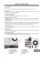
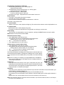
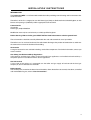
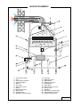
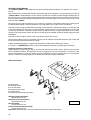
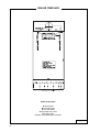
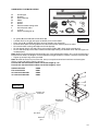
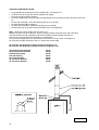
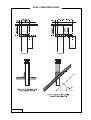
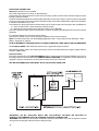
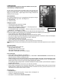
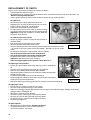
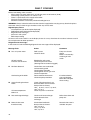
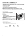
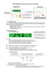
Wall hung combination boiler
PROTHERM 100EC
USER, INSTALLATION, AND
SERVICING INSTRUCTIONS
4728
THIS IS A CAT II2H3+ APPLIANCE
Technical Advice & After Sales Service
01773 828100
Protherm 100EC
Note: The boiler serial number is marked on the data label attached to the fascia behind the front panel.
Refer to the ‘Introduction’ section for a description of the basic functions of the boiler. The ‘User’ section
describes how to safely operate the boiler.
Users’ Instructions
Introduction ............................................................................................................................ 2
Controls and lighting .............................................................................................................. 2
Draining and filling .................................................................................................................. 4
Heating safety valve .............................................................................................................. 4
Servicing/maintenance ........................................................................................................... 4
Cleaning ................................................................................................................................. 4
Boiler casing .......................................................................................................................... 4
Installation Instructions
Introduction ............................................................................................................................ 5
Technical data ........................................................................................................................ 6
Dimensions ............................................................................................................................ 7
Pressure available ................................................................................................................. 7
Boiler schematic .................................................................................................................... 8
Installation section ................................................................................................................. 9
Terminal positions .................................................................................................................. 9
Heating and hot water system design .................................................................................. 10
Boiler installation ................................................................................................................ 11
Boiler template ..................................................................................................................... 12
Horizontal flue installation .................................................................................................... 13
Vertical flue installation ........................................................................................................ 14
Flue configurations ............................................................................................................... 15
Electrical connection ............................................................................................................ 16
Commissioning .................................................................................................................... 17
Servicing Instructions
Routine cleaning and inspection ...........................................................................................
Replacement of parts ...........................................................................................................
Schematic wiring diagram ....................................................................................................
Fault finding .........................................................................................................................
Conversion to LPG ...............................................................................................................
19
20
23
24
26
Mandatory warning for CE countries
WARNING, these appliances were designed, approved and inspected to meet the
requirements of the English market. The identification plate located on the inside of the appliance certifies
the origin where the product was manufactured and the country
for which it is intended.
If you see any exception to this rule, please contact your nearest stockist.
Thank you in advance for your assistance.
1
USERS INSTRUCTIONS
The Protherm 100EC is a wall mounted combination boiler providing central heating and instantaneous domestic hot water.
These instructions should be carefully followed for the safe and economical use of your boiler.
Gas leak or fault
If a gas leak or fault exists or is suspected, turn the boiler and gas supply off and consult the local gas
company or your Installer/Service provider.
In case of power supply failure
The boiler no longer operates.
As soon as power supply is restored, the boiler will restart automatically.
In case of loss of water in the system
CAUTION: The boiler is installed as part of a sealed system which must only be drained and filled by a
competent person.
If the pressure LED diod (2) flashes the pressure in CH system is less than 1 bar and the system must be
filled up immediately.
Important notice: A central heating system cannot operate satisfactorily unless it is properly filled with water
and unless the air initially contained in the piping systems has been properly bled off. If these conditions
are not satisfied, air noise will occur within the system and the boiler may fail to operate.
Air in the heating system
Persistent air in the heating system may indicate leaks in the system or corrosion taking place. Call your
Installer /Service provider.
Overheating safety
In the event of problem, the overheat safety device causes safety shutdown of the boiler. If this happens,
call your Installer/Service provider.
CONTROLS AND LIGHTING
The control panel is located at the lower front of the boiler casing. The controls on this panel allow the boiler
to be started, shut down, controlled and monitored during use, see diagram 1.
Controls:
1 – mains on/off switch
2 – system pressure LED
3 – central heating LED
4 – domestic hot water LED
5 – timeclock
6 – increase button
2
7 – pressure button
8 – reset button
9 – decrease button
10 – comfort mode LED
11 – mode button
12 – display
Diagram 1
The following information is displayed:
• Actual heating temperature (°C) - LED (3) lights on
displayed during standby
• Actual domestic hot water temperature (°C) - LED (4) lights
displayed during hot water demand
• System pressure (bar) – LED (2) lights
for 25 sec after Bar button is pressed
• Diagnostic messages – displayed letter F and numbers from 0 to 4
Make sure that:
• The boiler is connected to the electrical supply.
• The boiler gas service cock is open.
• The CH system is filled up and pressurized between 1 and 2 bar.
The boiler is now ready to start.
To start the boiler
Switch on the mains switch (display will light up). The version of the software used is displayed for 2 sec.
To stop the boiler
Switch off the mains switch (display will go out).
If the boiler is to be out of operation for a long period, turn off the gas service cock.
Boiler setting
All parameters are adjustable by means of 3 buttons, pushing the RESET button restarts the boiler.
Note: Buttons must be pressed in the middle.
Domestic hot water setting
• Press Mode button until LEDs (4) flash.
• Using buttons (6) and (9) set the desired hot water temperature.
Setting steps: 40, 42, 45, 48, 50, 52, 55, 58, 60 °C
• Set ´– –´ if hot water is not required.
• Press Mode button to save new setting.
Heating setting / summer mode setting
• Press Mode button until LED (3) flashes.
• Using buttons (6) and (9 set the desired heating temperature.
Setting steps: 45, 50, 55, 60, 65, 70, 75, 80, 85 °C
• Set ´– –´ if only hot water is required (summer mode).
• Press Mode button to save new setting.
The heating will operate according to the requirements of the timeclock and/
or room thermostat if fitted or, will operate according to the system requirements. Domestic hot water (DHW) always has priority over central heating
(CH).
Note: All new settings are stored by pressing MODE button. If MODE button is not pressed for 20 sec the display reverts to standby mode and
old settings are retained.
Helpfull hint
If you get confused and wish to start again, switch boiler off, press and
hold button (9) and switch boiler on by main switch. The boiler will revert to
the internal factory set programme (heating temperature 80 °C, hot water
temperature 50 °C, maximum heat output).
Timeclock
The boiler can be switched on and off automatically by the built-in timeclock. To set the timeclock, proceed as follows: (refering to diagram 1).
Press in the tappets corresponding to the time you want the boiler to be on.
For example if you want the boiler to be on between 7 AM and 9 AM, push in all the tappets between 7
and 9.
Set the times you want the boiler to be on for the rest of the day in the same way.
Note: The timeclock setting is in 24 hour format. Therefore, if you want the boiler to come on at 2 PM you
must push in the tappets at 14.
3
To set the correct time rotate the clock by hand until the current time is indicated by the arrow at the top
of the clock.
To operate the boiler according to your selected times, place the grey lever to the position.
To have the boiler permanently ‘ON’, place the grey lever to the ‘I’ position.
To have the boiler permanently ‘OFF’, place the grey lever to the ‘0’ position.
The comfort mode of domestic hot water
Comfort mode means that boiler is kept in pre-heated stage and waiting time for DHW delivery is shorten.
There are two ways of comfort DHW mode available:
Limited - if comfort mode of hot water is required only for limited time.
Open and close a bath tap (On/Off for interval between 2 and 5 seconds). It is automatically recognized
by boiler control unit and primary system water is preheated for immediate hot
water preparation.
Permanent - if comfort mode of hot water is required permanently.
Be sure, the display is in basic mode.
Press button (6).
Comfort LED (10) will light up - comfort mode is ON.
Comfort mode will OFF by next press of button (6) - diode (10) will go out.
Safety lockout
In the event of a safety lockout, the digital display will show ‘F1’.
Reset boiler by pressing the RESET button.
IMPORTANT: If safety lockout occurs frequently, or if any other fault is indicated,
contact your Installer/Service Provider.
DRAINING AND FILLING
CAUTION: The boiler is installed as part of a sealed system which must only be drained and filled by a
competent person.
If the pressure drops to 1 bar the pressure LED on the Bar button starts to flash. The boiler will continue to
work, but the LED warns that pressure in the CH system is on the low limit and CH system must be filled.
To fill the system, open the tap on the filling loop below the boiler. Press the Bar button to read the system
pressure. When the pressure is between 1 and 2 bar, close the tap.
Note: If there is persistent loss of system pressure, you must consult your Installer/Service Provider.
HEATING SAFETY VALVE
CAUTION: A safety valve with a discharge pipe is fitted to this boiler.
The valve MUST NOT BE TOUCHED except by a competent person. If the valve discharges at any time,
switch the boiler off and isolate it from the electrical supply. Contact your Installer/Service Provider.
SERVICING / MAINTENANCE
To ensure the continued efficient and safe operation of the boiler, it is recommended that it is checked and
serviced at regular intervals. The frequency of servicing will depend upon the installation conditions and
usage but, in general, once a year should be enough.
CLEANING
The boiler casing can be cleaned with a damp cloth followed by a dry cloth to polish.
Do not use abrasive or solvent cleaners.
BOILER CASING
CAUTION: Do not remove or adjust the casing in any way, as incorrect fitting may result in faulty operation.
If in doubt, contact your Installer/Service Provider.
4
INSTALLATION INSTRUCTIONS
INTRODUCTION
The Protherm 100EC is a wall mounted combination boiler providing central heating and instantaneous domestic hot water.
The boiler is of the II2H3+ category for use with Natural gas (G20) as distributed in the United Kingdom, or with
Butane or Propane gas (G30/G31) with the appropriate conversion kit.
Conversion kit:
Conversion
Natural gas (G20) to G30/G31
Modification must only be carried out by a suitably qualified engineer.
Boilers burning LPG or similar gases MUST NOT be fitted in basements or below ground level.
These instructions should be carefully followed for the safe and economical use of your boiler.
The boiler has a fan assisted, balanced, flue which both discharges the product of combustion to, and draws
the combustion air from the outside of the building.
Accessories
A range of accessories are available including, vertical flue components. For further information, contact you
nearest stockist.
Gas Safety (Installation and Use) Regulations
In the interests and that of gas safety, it is the law that ALL gas appliances are installed and serviced in by a
competent person in accordance with the above regulations.
Gas leak or fault
If a gas leak or fault exists or is suspected, turn the boiler and gas supply off and consult the local gas
company or your Installer/Service Provider.
Boiler controls
The control panel, located at the lower front of the boiler, allows the boiler to be started, shut down, controlled
and monitored during use, refer to ‘Users Instructions’.
5
TECHNICAL DATA
CE Certification .............................................. n° ............................................................... 49AU2915
Class .......................................................................................................................................... II2H3+
Type ........................................................................................................................................ C12, C32
Gas type ....................................................................................... G20 ............... G30 ................. G31
Max. / min. heat input .................................... kW ..................... 30.5/12.1 ....... 30.5/12.1 ..... 30.5/12.1
Max. / min. heat output ................................. kW ..................... 27.4/10.0 ....... 27.4/10.0 ..... 27.4/10.0
EFFICIENCY (PCI)
Nominal efficiency .......................................... % ........................................................................ 89.8
Efficiency at 30% load .................................... % ........................................................................ 86.7
HEATING
Temperature range ......................................... °C .................................................................... 45 – 85
Expansion vessel ............................................. l ............................................................................. 7
Expansion vessel pressure ........................... bar ............................................................................. 1
Max. working pressure .................................. bar ............................................................................. 3
Max. system temperature .............................. °C ........................................................................... 85
Max. system capacity ....................................... l ..........................................................................130
HOT WATER
Flow rate at 30°C temperature rise .............. l/min ........................................................................ 13.1
Flow rate at 35°C temperature rise .............. l/min ........................................................................ 11.3
Min. water flow ............................................ l/min ............................................................................. 2
Max. / min. supply pressure .......................... bar ........................................................................ 6 / 1
Temperature range ......................................... °C .................................................................... 40 – 60
ELECTRICAL DATA
Voltage / frequency .................................... V/Hz ................................................................ ~230 / 50
Current ............................................................. A .......................................................................... 0.8
Power .............................................................. W ..........................................................................160
Level of protection .......................................... IP ....................................................................... IP 44
DIMENSIONS
Width / height / depth ................................... mm .......................................... .............450 / 800 / 355
Weight ........................................................... kg ........................................................................... 42
CONNECTIONS
Heating flow / return ..................................... mm ........................................................................... 22
Domestic Water inlet / outlet ........................ mm ........................................................................... 15
Gas .............................................................. mm ........................................................................... 22
Flue products outlet / air inlet ∅ ..................... mm ....................................... horiz. 60/100, vert. 80/125
Horizontal flue length min. – max. ................... m .................................................................... 0.3 – 3
Vertical flue length min. – max. ....................... m ................................................................ 0.5 – 11.5
GAS SUPPLY PRESSURE
Burner pressure ......................................... mbar ..................... 2.1 – 15.0 ..... 3.8 – 28.8 .... 4.1 – 36.7
Nominal pressure ....................................... mbar ........................... 20 ................. 29 ..................... 37
Injectors diameter .................................... ∅ mm .......................... 1.2 .............. 0.73 ................ 0.73
GAS CONSUMPTION
3
Q max / Q min ............................................ m /h ...................... 3.2 / 1.3 ....... 1.1 / 0.5 ....... 1.4 / 0.6
3
Air flow ........................................................ m /h .......................... 135 ............... 135 ................... 135
6
DIMENSIONS AND PRESSURE AVAILABLE
Diagram 2
1 – Heating flow (pipe diameter 22 mm)
2 – Hot water outlet (pipe diameter 15 mm)
3 – Gas inlet (pipe diameter 22 mm)
4 – Cold water mains inlet (pipe diameter 15 mm)
5 – Heating return (pipe diameter 22 mm)
6 – Wall
7 – Wall fixings
8 – Outer cover
Diagram 3
7
BOILER SCHEMATIC
1 – Air pressure switch
2 – Fan
3 – Combustion chamber
4 – Heat exchanger
5 – Burner
6 – Gas valve
7 – Expansion vessel
8 – Pump
9 – Water flow sensor
10 – Safety valve
11 – Heating return
12 – Domestic cold water inlet
13 – Gas inlet
14 – DHW thermistor
15 – DHW outlet
16 – Automatic by-pass
17 – Heating flow
18 – Drain point
19 – Water pressure sensor
20 – 3-way valve
21 – Actuator
22 – Domestic heat exchanger
23 – CH temperature sensor
24 – High limit thermostat
Diagram 4
8
INSTALLATION
SECTION
Clearances
To allow for servicing, the boiler should be installed with the following clearances:
50 mm either side of the boiler
600 mm to the front of the boiler
300 mm below the boiler
200 mm above the boiler
TERMINAL POSITION
The minimum acceptable spacings from the terminal to obstructions and ventilation openings are shown in
diagram 5 below:
Diagram 5
Minimum dimensions (in mm) for the positioning of flue terminals
a
b
c
d
e
f
g
h
i
l
m
n
Under a window . . . . . . . . . . . . . . . . . . . . . . . . . 300
Under an air vent . . . . . . . . . . . . . . . . . . . . . . . 300
Under a gutter . . . . . . . . . . . . . . . . . . . . . . . . . . . 75
Under a balcony . . . . . . . . . . . . . . . . . . . . . . . . 300
From an adjacent window . . . . . . . . . . . . . . . . . 300
From an adjacent air vent . . . . . . . . . . . . . . . . . 300
From vertical drain pipes or soil pipes . . . . . . . . . 75
From an external corner of the building . . . . . . . 300
From an internal corner of the building . . . . . . . . 300
From the ground or from another floor . . . . . . . . 300
Between two terminals vertically . . . . . . . . . . . 1500
Between two terminals horizontally . . . . . . . . . . 300
9
HEATING SYSTEM DESIGN
The Protherm 100EC is compatible with any type of sealed system installation, i.e. radiators, fan convectors etc.
Pipe sectional areas shall be determined in accordance with normal practices, using the pump curve, refer to
‘Technical Data’. The distribution system shall be calculated in accordance with the output requirements of
the actual system, not the maximum output of the boiler. However, provision shall be made to ensure sufficient
flow so that the temperature difference between the flow and return pipes is less than or equal to 20 °C. The
minimum flow is 500 l/h.
The piping system shall be routed so as to avoid any air pockets and facilitate permanent venting of the
installation. Bleed fittings shall be provided at every high point of the system and on all radiators.
The total volume of water permitted for the heating system depends, amongst other things, on the static head
in the cold condition. The expansion vessel on the boiler is pressurised at 1 bar (corresponding to a static head
of 10 m wg.) and allows a maximum system volume of 130 litres for an average temperature of 75 °C and a
maximum service pressure of 3 bar. This pressure setting can be modified at commissioning stage if the static
head differs.
Provision shall be made for a drain valve at the lowest point of the system.
Thermostatic radiator valves are permitted, however, not all radiators must be fitted with this type of valve and
particularly where the room thermostat is fitted.
A WRC approved filling loop is supplied with the boiler to enable correct filling of the system.
In all cases, it is ESSENTIAL that the system be thoroughly flushed prior to installing the new boiler.
Domestic hot water system design
Copper tubing or plastic Hep2O may be used for the domestic hot water system. Unnecessary pressure
losses should be avoided. The domestic hot water supply pressure must be between 1 and 6 bar. If the
pressure exceeds 6 bar, a pressure reducing valve must be fitted. In known hard water areas, it is recommended that a suitable scale reducing device is fitted to the cold water supply to the boiler.
Boiler connections
A
B
C
D
E
F
Heating flow
Hot water outlet
Gas connection
Cold water mains inlet
Heating return
Safety valve discharge connection
Heating system connections
- Pipe diameter 22 mm.
Hot water system connections
- Pipe diameter 15 mm.
Gas connection
- Pipe diameter 22 mm.
Safety valve discharge connection
- Pipe diameter 22 mm.
Note: White colored washers must be used for the hot water system connections.
10
Diagram 6
Safety valve discharge
WARNING: It must not discharge above an entrance or window or any type of public access area.
Connect the safety valve discharge pipe to the valve, the discharge must be extended using not less than
15 mm o.d. pipe, to discharge in a visible position outside the building, facing downward, preferably over a
drain. The pipe must have a continuous fall and be routed to a position so that any discharge of water,
possibly boiling or steam, cannot create any danger to persons, damage to property or external electrical
components and wiring. Tighten all pipe connection joints.
Gas connection
The supply from the governed meter must be of adequate size to provide a constant inlet working pressure
of 20 mbar for Natural gas (28 – 30 mbar for Butane or 37 mbar for Propane).
To avoid low pressure problems, it is recommended that the supply is taken to the boiler using 22 mm pipe
as far as possible.
On completion, the gas installation must be tested using the pressure drop method and purged in accordance with the current issue of BS6891.
Gas Safety (Installation and Use) Regulations
In your interests and that of gas safety, it is the law that ALL gas appliances are installed and serviced by
a competent person in accordance with the above regulations.
Statutory requirements
The installation of this boiler must be carried out by a competent person in accordance with the relevant
requirements of the current issue of:
The Gas Safety (Installation and Use) Regulations
The Building Regulations
The local water company Bylaws
The Building Standards Regulations (Scotland)
The Health and Safety at Work Act
Sheet metal parts
WARNING: When installing or servicing this boiler, care should be taken when handling the edges of sheet
metal parts to avoid the possibility of personal injury.
Installing the boiler
Prior to installing the boiler, the system must be thoroughly flushed to eliminate any foreign bodies and
contaminents such as filings, solder, particles, oil, grease etc.
Note: Solvent products could cause damage to the system.
BOILER INSTALLATION
To install the boiler, proceed as follows:
• Allowing sufficient clearances for servicing/repair, place the template on the wall (see diagram 7).
Note: The boiler can be installed only on the closed wall.
• Determine the position of the flue hole and drill hole for flue, preferably using a 120 mm core drill.
• Drill two 10 mm holes for the wallplugs supplied.
• Screw fixing screws supplied into wallplugs, leave proud by approx. 10 mm.
Note: Boiler fixing holes are keyhole type slots at the top of the boiler to allow easy hanging of boiler.
• Remove template.
• Hang the boiler on the screws and tighten screws.
Note: As a option the hanging bracket can be used. Two screws are sufficient for fixing of the hanging
bracket. Hanging bracket fixing screws have to be fully tight before the boiler is hung on.
Pipework connections
• Remove plastic caps from boiler connections.
• Connect the central heating pipework connections and isolating cocks as shown on diagram 6.
• Connect the domestic cold water inlet connection and isolating cock.
• Connect the hot water outlet connection.
• Connect the safety valve discharge pipe.
• Finally, connect the gas connection and isolating cock.
11
BOILER TEMPLATE
Boiler connections
A Heating flow
B Hot water outlet
C Gas connection
D Cold water mains inlet
E Heating return
F Safety valve discharge connection
Diagram 7
12
HORIZONTAL FLUE INSTALLATION
A
B
C
D
E
F
G
I
J
K
Air inlet pipe
Terminal
Seal and clamp
Elbow
Gasket
Screws
External rubber sealing collar
Internal plastic collar
‘O’ rings
Spacer (see diagram 9)
•
•
•
•
•
•
•
Fit gasket (E) onto underside of flue elbow (D).
Diagram 8
Carefully insert ‘O’ ring (J) into upper and lower parts of inner elbow.
Place spacer (K) (supplied with boiler) onto top of boiler (see diagram 9).
Fit elbow onto spacer ensuring elbow inner connection locates correctly onto fan outlet.
Fit external rubber sealing collar (G) onto air inlet pipe (A).
Fit flue through hole in wall and pull up so that external collar (G) is flush against outside wall.
Fit seal and clamp (C) to flue and assemble into elbow (D) making sure that both inner and outer pipes are
sealed properly.
Note: Maximum horizontal length with no bends is 3 m. For horizontal flue lengths up to 1 m the restrictor must
be left in the fan outlet, see diagram 9. For horizontal flue lengths between 1 and 3 m, remove the restrictor (R).
• Tighten up clamp using screws provided.
Note: Should it be necessary to cut the flue, always cut equal amounts from both inner and outer pipes.
Always cut the end furthest from the terminal.
For each 90° flue bend fitted, reduce overall flue length by 1 m.
For each 45° flue bend fitted, reduce overall flue length by 1/2 m.
Horizontal flue kit
Flue extension kit
90° concentric bend kit
45° concentric bend kit
85090
85091
85092
85093
Diagram 9
Standart top
outlet flue
Standart top
outlet flue
90° elbow
Extension
pipe
13
VERTICAL FLUE INSTALLATION
•
•
•
•
•
•
•
•
Fit gasket (E) onto underside of vertical adaptor (O) – see diagram 10.
Carefully insert ‘O’ ring (J) into vertical adaptor inner spigot.
Place spacer (K) on the top of boiler.
Fit vertical adaptor (O) onto spacer (K) ensuring adaptor inner connection locates correctly onto fan outlet.
For flat roof installation, fit flat roof flashing collar (part no. 85107)
Fit extension pipes (M) as required.
For pitch roof installation, fit pitch roof flashing (part no. 85105).
Fit flue terminal (L) onto roof ensuring flashing makes a watertight joint.
Note: Maximum vertical height with no bends is 5 m.
Should it be necessary to cut the flue, always cut equal amounts from both inner and outer pipes.
Connect condensate trap (supplied) to vertical flue adaptor when flue length exceeds 3 m.
Connect 15 mm plastic pipe (not supplied) to a suitable drain.
For vertical flue lengths up to 3 m the restrictor must be left in the fan outlet, see diagram 9.
For vertical flue lengths between 3 and 5 m, remove the restrictor (R).
For each 90° flue bend fitted, reduce overall flue height by 1 m.
For each 45° flue bend fitted, reduce overall flue height by 1/2 m.
Vertical flue terminal (black)
Vertical flue terminal (brick)
Pitched roof flashing
Flat roof flashing
Flue extension pipe
90° concentric bend kit
45° concentric bend kit
85103
85104
85105
85107
85099
85101
85102
Diagram 10
14
FLUE CONFIGURATIONS
Diagram 11
15
ELECTRICAL CONNECTION
Warning: This boiler must be earthed.
All system components must be of an approved type.
Connection of the whole electrical system and any heating system controls to the electrical supply must be
through a common isolator.
Isolation should preferably be by a double pole switched fuse spur box having a minimum contact separation
of 3 mm on each pole. The fused spur box should be readily accessible and preferably adjacent to the boiler.
It should be identified as to its use.
A fused three pin plug and shuttered socket outlet may be used instead of the fused spur box, provided that:
a) They are not used in a room containing a bath or shower.
b) Both the plug and socket comply with the current issue of BS1363.
The mains electrical supply must be maintained at all times in order to provide domestic hot water and frost
protection.
It is recommended that a room thermostat is fitted.
Thermostatic radiator valves may be installed in addition to the room thermostat.
Note: For further information, see The Building Regulations 1991 - Conservation of fuel and power - 1995
edition - Appendix G, table 4b.
DO NOT INTERRUPT THE MAINS SUPPLY TO THE BOILER WITH A TIME SWITCH OR PROGRAMMER.
The Protherm 100EC is delivered with 1metre mains supply lead ready connected.
The electrical supply cable is the original spare part and must be replaced only by original supply cable for
Protherm 100EC boiler.
External controls
The boiler will work for heating AS DELIVERED without a room thermostat fitted provided the two wires on
the integral external controls connection REMAIN LINKED TOGETHER (as supplied). If a room thermostat is
required, it must be connected as shown below and the link must be removed.
ANY ROOM THERMOSTAT USED MUST BE OF THE VOLTAGE FREE TYPE.
Diagram 12
WARNING: ON NO ACCOUNT MUST ANY ELECTRICAL VOLTAGE BE APPLIED TO
EITHER OF THE TERMINALS OF THE EXTERNAL CONTROLS CONNECTION
WARNING: This boiler must be wired in accordance with these instructions. Any fault arising from incorrect
wiring cannot be put right under the terms of the guarantee.
16
COMMISSIONING
The commissioning and first firing of the boiler must only be
carried out by a competent person.
To gain access to the inside of the boiler undo screw securing front
panel at the boiler bottom, remove front panel by pulling forwards,
lifting it up and off. Note – upper edge of front casing is fixed to the
boiler by means of 2 pins.
Gas installation
It is recommended that any air is purged from the supply at the gas
inlet test point on the gas valve, see diagram 13.
1 - Inlet test point
2 - Outlet test point
Filling the system
• Check that the gas meter tap is closed.
• Conect boiler to electrical supply.
• Place switch (1) diagram 1 to possition “I”. F0 is displayed and
the pump runs for about one minute.
• Press the BAR button, see diagram 1. Value of system pressure (0.0) is displayed
Diagram 13
and LED (2) – see diagram 1 – lights.
Note: The pressure is displayed for about 25 sec. After this time the display comes
back to the standby mode. The pressure can be displayed after pressing Bar push button again.
• Open isolating valves (A, E and D) see diagram 6.
• Undo, but not remove, cap on automatic air vent on the top of the pump.
• Fill system by opening system filling loop until a pressure of between 1 and 2 bar is shown on the display.
• Bleed each radiator until a continuous jet of water is obtained.
• Do not retighten automatic air vent cap.
• Open various hot water taps to bleed hot water circuit.
• Make sure that pressure is between 1 and 2 bar. Re-pressure as necessary.
Important: When venting air from boiler, do not touch the schrader valve on the expansion vessel, it is NOT a
vent.
Starting the boiler
Before starting the boiler check that:
- The gas meter tap is open.
- The boiler gas service cock is open.
- The water isolating cocks are open.
- The boiler is connected to the electrical supply.
First starting up
• Place main switch (1) diagram 1 to position “I”.
• Set maximum heating water temperature (85°C), as described in ‘Users Instructions’ and check that any
external controls, if fitted, are calling for heat.
• Allow the temperature to rise to the maximum value, with all radiator valves open. Air contained in the water
of central heating system will be automatically released through the automatic air vent. Air trapped at the
hightest point of the system must be released by bleeding the radiators.
On reaching maximum temperature, the boiler should be turned off and the system drained as rapidly as
possible whilst still hot.
• Refill system to a pressure at least of 1 bar and vent as before.
• Restart boiler and operate until a maximum temperature is reached. Shut down boiler and vent air from
heating system. If necessary, top up heating system and make sure that a pressure at least of 1 bar is
indicated on the display when system is COLD.
Gas pressures
• Shut down boiler.
• Undo screw on gas inlet test point ‘1’ on gas valve, see diagram 13.
• Connect a suitable pressure gauge.
• Start boiler as described in ‘Users Instructions’.
17
• Check that there is a constant pressure of 20 mbar for Natural gas (28 – 30 mbar for Butane or 37 mbar for
Propane). If the pressure is insufficient, it is necessary to check the gas supply/pipework and correct any
fault.
• Shut down boiler.
• Remove pressure gauge, tighten up carefully test point screw and check for gas soundness.
Setting the central heating output
The central heating output must be set in accordance with the system requirements.
Setting procedure as follows:
• Push and hold the Mode button for at least 8 sec. The display will switch to service mode, the symbol nwill be displayed
• Set the desired output value from n1 to n9 by means of buttons (6)
and (9) according to the following table:
n1
n2
n3
n4
n5
.....
.....
.....
.....
.....
kW
9.3 . . . . .
11.0 . . . . .
12.0 . . . . .
14.0 . . . . .
16.0 . . . . .
Btu/hr
31 732
37 532
40 944
47 768
54 592
n6
n7
n8
n9
n-
....
....
....
....
....
kW
Btu/hr
18.0 . . . . . 61 416
20.0 . . . . . 68 828
22.5 . . . . . 76 770
23.3 . . . . . 79 499
23.3 . . . . . 79 499 (max. output)
• Press Mode button to save and return to main menu.
Safety devices
Diagram 14
Air flow rate safety device
If an obstruction, even partial, of the flue occurs, the built in safety system of the boiler will turn the boiler OFF.
The boiler will be ready to operate when the fault has been cleared.
In case of power supply failure
The boiler no longer operates. As soon as power is restored, the boiler will be automatically restarted. If the
boiler does not restart, the overheat device may need resetting.
Overheat safety
In the event of overheating, the overheat safety device causes safety shutdown of the boiler. The digital display will show error code F1. To reset, let the
boiler cool down, press the reset button on the safety device (a), see diagram
22 and reset boiler controls by means of the reset button (8).
Note: wire connections to overheat thermostat are mains voltage.
Important notice
A central heating system cannot operate satisfactorily unless it is properly
filled with water and unless the air initially contained in the pipework system
has been properly bled off. If these conditions are not satisfied, air noise will
occur within the system and the boiler may fail to operate.
To reset the boiler (other than for overheating) use the reset button on the
fascia, see diagram 15.
Diagram 15
The Protherm 100EC boiler has a built-in frost protection device that protects the boiler during freezing
conditions. This device works irrespective of any room thermostat setting and only protects the boiler.
Should the temperature within the central heating circuit of the boiler fall below 10 °C, the pump will switch on
providing the electrical supply has been left connected. If the temperature falls below 8 °C, then the burner will
operate until the water temperature increases to 25 °C. Should the electrical supply have been disconnected
and the boiler/system has frozen, the boiler will not start up until the boiler/system has been cleared.
18
SERVICING INSTRUCTIONS
To ensure the continued efficient and safe operation of the boiler, it is recommended that it is checked and
serviced at regular intervals. The frequency of servicing will depend upon the installation conditions and usage
but, in general, once a year should be enough.
It is the law that any servicing is carried out by a competent person.
ROUTINE CLEANING AND INSPECTION
•
•
•
Operate boiler and check for any faults that need to be put right.
Isolate boiler from the gas and electrical supplies.
On completion check all gas carrying parts for soundness with leak detection fluid.
Remove boiler casing as follows:
Outer casing
• Undo screw securing the casing underneath boiler and remove outer
casing by pulling forwards, lifting it up and off.
Sealed chamber
• Unclip two clips holding sealed chamber cover to boiler and lift it forwards and off.
Side covers
• Undo 3 screws securing each of side covers and remove outer covers
by pulling to side, forwards and off.
Sealed chamber
•
Unclip two clips holding sealed chamber cover to boiler and lift it up
and off, see diagram 16.
Cleaning the burner
• Unscrew and remove 6 screws securing combustion chamber cover and remove cover.
• Disconnect flame sense electrode at burner.
• Disconnect ignition lead at gas valve module.
• Disconnect ignition earth lead.
• Undo nuts (A) securing gas supply pipe between burner
and gas valve and remove pipe, see diagram 17.
Note: The washer between the burner and burner gas supply
must be kept to use on reasembly.
• Unscrew 2 screws (B) securing burner to base of sealed
chamber.
• Pull main burner up and forward out of boiler.
• Examine and clean burner as necessary.
Diagram 16
Note: DO NOT use a wire or sharp instrument on the holes.
Heat exchanger
• Locate the heat exchanger inside the sealed chamber.
• Gain acces to heat exchanger by removing fan and flue
hood.
• Examine heat exchanger for any blockages or build up of deposits.
• Clean heat exchanger with soft brush or vacuum cleaner.
Diagram 17
Reassembly of parts removed for servicing
All parts are replaced in reverse order to removal.
Flue system
• Check externally to make sure that flue is not blocked.
• Inspect flue system to make sure that all fittings are secure.
Operation of fan
• Switch on electrical supply and turn on gas.
• Remove sealed chamber cover.
• Light burner by operating external controls (if fitted) to call for heat.
• Check that fan operates when burner lights and stops when it goes out.
19
REPLACEMENT OF PARTS
To gain access to the boiler components, proceed as follows:
• Isolate boiler from electrical supply.
• Remove outer case, if necessary sealed chamber cover, combustion chamber cover and side covers, see
“Routine cleaning and inspection”.
• Gently squeeze metal clip securing the control panel box, lift it up and hinge down.
To replace fan
• Disconnect power supply and earth leads to fan.
• Supporting fan, unscrew and remove two screws securing fan to front of flue hood, see diagram 18.
• Gently ease fan forwards and out of boiler.
• Fit replacement fan in reverse order to removal making
sure that mounting plate engages correctly onto flue hood
Important: Ensure that fan outlet is correctly fitted into
flue elbow at top of boiler.
To replace air pressure switch
• Locate air pressure switch in upper left hand corner of
sealed chamber.
• Pull off clear plastic tube from base of switch.
• Remove electrical connections from switch.
• Unscrew and remove two screws securing switch to upper panel and remove switch
– (or unclip air pressure switch from plastic holder – depends on type of switch
used).
• Fit electrical connections to replacement switch as follows:
One to the microswitch connection marked ‘NO 2’
One to the microswitch connection marked ‘COM 3’
• Fit replacement switch in reverse order to removal.
Important: Refit clear plastic tube as follows:
Tube from tapping point of flue hood to switch point ‘P 2 -’
To replace gas valve module
• Locate gas valve module attached to side of gas valve, see diagram
19.
• Unscrew screw (a) securing cover onto gas valve module.
• Remove cover and disconnect multi-plug from module.
• Disconnect ignition and flame sense leads from module and withdraw
module from gas valve.
• Fit replacement module in reverse order to removal.
• Reconnect ignition and flame sense leads, the connections are uniquely
sized to ensure correct replacement.
• Refit cover ensuring all sealing grommets are correctly located in module body.
Diagram 18
Diagram 19
To replace gas valve
• Ensure that gas supply is turned off at gas cock.
• Unscrew screw (a) and remove gas valve module.
• Undo nuts securing gas supply pipe between burner and gas valve and remove pipe, taking care not to lose
sealing washers, see diagram 19.
• Remove gas inlet connection to boiler.
• Unscrew 2 screws securing gas valve to boiler bottom.
• Remove gas valve by lifting upwards and out of boiler.
• Fit replacement gas valve in reverse order to removal.
• Check for gas-tightness.
To replace burner
• Remove burner as described in ‘Cleaning the burner’.
• Fit replacement burner in reverse order to removal.
• Check if the injectors are correct.
20
To replace pump
Drain down heating circuit only of boiler as follows:
• From below boiler, close isolating valves on flow and
return connections to boiler.
• Open boiler drain valve on left hand side of hydraulic block.
Note: It is not necessary to drain down entire heating circuit to carry out this work.
Simplification: for simpler work remove gas valve
module and right side cover.
• Disconnect pump cable.
• Remove 2 clips fixing pump, see diagram 20.
• Unscrew 2 screws securing the pump to boiler
bottom.
• Lift up the pipe and remove pump by lifting forward and out of boiler.
• Fit replacement pump in reverse order to removal.
• Open isolating valves on flow and return connections.
• Refill, vent and pressurise boiler. Check for leaks.
Diagram 20
To replace safety valve
• Drain down heating circuit of boiler as described previously.
Simplification: for simpler work remove gas valve module and pump as described previously.
• Remove expansion vessel hose from hydraulic block.
• Remove draining pipe from safety valve and unscrew safety valve.
• Fit replacement safety valve in reverse order to removal.
Important: Seal the safety valve thread by jointing compound.
To replace domestic heat exchanger
• Drain down heating circuit of boiler as described previously.
Drain down hot water circuit of boiler as follows:
• From below of boiler, close cold water inlet isolating valve.
• Open a hot tap to drain hot water circuit.
• Remove gas valve.
• Unclip pump and pull forwards.
• Disconnect expansion flexible hose at connection to
vessel fixing.
• Remove fixing screws and plate exchanger over hydraulic block, see diagram 21.
• Fit replacement heat exchanger in reverse order to removal, ensuring seals are correctly positioned in hydraulic
block.
• Open isolating valves on flow and return connections,
refill, vent and pressurise boiler. Check for leaks.
• Open cold water isolating valve. Check for leaks.
Diagram 21
To replace overheat thermostats
Important: Isolate boiler from electrical supply before this
operation – connections to overheat thermostats are
mains voltage.
• Locate overheat thermostats (a) and (c) to left hand side
of sealed chamber above thermistor, see diagram 22.
• Unclip thermostat from pipe.
• Pull off electrical connections from thermostat.
• Fit replacement thermostat in reverse order to removal.
Note: No heat sink compound is required. The polarity of
the connections is not important.
Diagram 22
21
To replace heating water thermistor
• Locate thermistor (b) clipped onto flow pipe to left hand side of sealed chamber below overheat thermostat,
see diagram 22.
• Unclip thermistor from pipe.
• Pull off electrical connections from thermistor.
• Fit replacement thermistor in reverse order to removal.
Note: No heat sink compound is required. The polarity of the connections is not important.
To replace hot water thermistor
• Pull off electrical connections from thermistor and unscrew thermistor (b) from left part of hydraulic block,
see diagram 21.
• Remove gas valve module as described previously.
• Fit replacement thermistor in reverse order to removal.
Note: The polarity of the connections is not important.
To replace printed circuit board (PCB)
Important: Isolate boiler from electrical supply before this operation.
• Gently squeeze metal clip securing the control panel box, lift it up and hinge down.
• From behind control panel box, unscrew and remove 4 screws securing PCB cover to panel.
• Pull off electrical plugs from PCB.
• Remove 4 screws securing PCB to panel and lift out PCB.
• Fit replacement PCB in reverse order to removal.
To replace display and control panel board
Important: Isolate boiler from electrical supply before
this operation.
• Remove PCB cover as described in ‘To replace PCB’.
• Pull off electrical plug of display (A) from PCB, see
diagram 23.
• Remove 4 screws securing PCB to panel and lift out
PCB.
• Remove 4 screws securing display and control panel
bord to panel and gently lift it out.
• Fit replacement display and control panel board in reverse order to removal.
To replace timeclock
• Remove PCB cover as described in ‘To replace PCB’.
• Disconnect clock electrical connections from PCB. Unclench plastic clips securing
timeclock to lower front panel and remove timeclock from panel.
• Fit replacement timeclock in reverse order to removal.
Diagram 23
To replace pressure gauge
• Drain boiler as described in ‘To replace pump’.
• Unclip pressure gauge clip and pull it out.
• Disconnect pressure gauge cable.
• Fit replacement pressure gauge in reverse order to removal.
To replace heat exchanger
• Drain down heating circuit of boiler only as described previously.
• Remove sealed and combustion chamber covers and side
cases as described previously.
• Remove overheating termostats from heat exchanger pipes.
• Pull off spring clips securing heat exchanger pipes to heat
exchanger.
• Manoeuvre heat exchanger pipes down to disengage from heat
exchanger.
• Remove heat exchanger by sliding forward and out of boiler.
• Fit replacement heat exchanger in reverse order to removal.
• Open isolating valves on flow and return connections, refill,
vent and pressurise boiler. Check for leaks.
22
Diagram 24
SCHEMATIC WIRING DIAGRAM
Diagram 25
23
FAULT FINDING
Before fault finding, make sure that:
- All gas cocks are open and there is an inlet gas pressure of 20 mbar (G 20).
- The heating system pressure is at least 1 bar.
- There is a permanent mains supply to the boiler.
- The fuses on the PCB are intact.
- All external controls are correctly wired and calling for heat.
WARNING: Always isolate the boiler from the electrical supply before carrying out any electrical replacement work. Always check for gas soundness after any service work.
Digital display shows:
- CH temperature (no decimal point displayed)
- DHW temperature (decimal point displayed)
- diagnostic error messages
- pressure in CH system
- boiler output setting
As soon as the mains switch is on the display shows for a very short time the version of software used. It
has no importance for boiler operation.
Diagnostic error messages
In the event of a fault the following diagnostic error messages will be displayed:
Message Fault
Action
Comments
F0 Loss of system water
Refill system
Check for leaks
Pump runs for one
minute
Boiler is restarted by
switching of main
switch
Air lock in boiler
Pressure sensor failure
F1 No flame detected
Overheating of the boiler
F2 Central heating thermistor
failure
CH water temperature
below 3°C
Bleed boiler and system
Check the pressure sensor
(Sensing inlet must not be clogged)
Check flame sense electrode
and connecting cable
Check ignition electrode
Check ignition unit on gas valve
Check fan operation
Reset overheat thermostats
Check the pump revolution
If overheat thermostats are blocked,
boiler does not ignite
when starting
Check if flow thermistor is not
disconnected or short-circuited
Sensor Ohm resistance
10 kΩ by 25°C, 12,7 kΩ by 20°C,
16 kΩ by 15°C
Check if system is not frozen
F3 Heat exchanger blockage
Check main heat exchanger
Check domestic heat
exchanger
Boiler shuts down and
pump runs
F4 Domestic hot water
thermistor faulty
Check thermistor/leads
Sensor Ohm resistance:
10 kΩ by 25°C
12,7 kΩ by 20°C
16 kΩ by 15°C
Domestic hot water is
available bur poor
24
Air pressure switch failure:
If the fan and the pump is running but the boiler doesn’t light, check the air pressure switch.
Blown fuses:
If the main switch is on and display does not light check the FUSE 1 (T1.6A), see diagram 23.
The pump, the fan and the ignition module don’t work.
Warning message:
If the pressure in CH system drops to 0.8 bar the LED on the Bar button starts to flash. This give you
information that CH pressure is on the low limit and must be pressurised. Nevertheless the boiler works until
the pressure drops to 0.6 bar – then boiler shuts down and F0 is displayed.
DHW flow is poor
If DHW floor is poor or boiler does not start when hot water tap is open, check following:
Cold water supply pressure is at least 1 bar.
Check if the cold water filter or flow regulator (plastic “O” ring) is not clogged.
Check free movement of the magnetic shunt (mounted inside cold water filter).
Note: The Hall Effect Sensor is polarity sensitive, consequently the magnet must be kept in the exact
position. Before completely dismantling the Flow Detector, print a mark on the visible face of the magnet, in
order to reassemble it with the right polarity.
25
PROTHERM 100EC – CONVERSION TO LPG
Note: Conversion must only be carried out by a competent person
• Isolate boiler from the gas and electrical supplies.
• Remove boiler casing, sealed chamber and combustion chamber cover as described in Installation/Servicing Instructions.
• Disconnect flame sense electrode.
• Disconnect ignition lead at gas valve module.
• Disconnect ignition earth lead.
• Undo nuts securing gas supply pipe between burner and gas valve and remove pipe.
• Undo two locking nuts securing burner to base of sealed chamber.
• Pull main burner up and forward out of boiler.
Note: The washer between the burner and burner gas supply must be kept to use in reassembly.
• Unscrew and remove two injector bars retaining screws and separate injector bar from burner.
• Fit new injector bar with marked diameter of injector ∅ 0,68 mm to the boiler in reverse order to removal.
• Readjust the gas valve.
GAS VALVE ADJUSTMENT
To adjust the minimum and maximum settings, proceed as follows:
• Gain access to the rear of the controls housing.
• Connect a manometer to the burner pressure test point (2) on
the gas valve.
Minimum setting
• Start boiler in Central Heating mode, boiler is working in minimum output for 100 seconds.
• Adjust the gas valve minimum pressure using screw (C) on gas
valve. Turn clockwise to increase, anti-clockwise to decrease.
Maximum setting
• Start boiler in Domestic Hot Water mode.
• Adjust gas valve maximum pressure using screw (B). Turn clockwise to increase, anti-clockwise to decrease.
Note: It is first necessary to remove cover (A) to gain access to
screw (B).
Finaly
• Disconnect manometer and check for gas soundness.
• Check for gas soundness.
• Replace the PCB box and all covers.
• Stick the self-adhesive label (delivered with LPG conversion kit) bearing the information about the gas type
and the gas supply pressure on the visible place inside the boiler.
G20 (20 mbar)
G30 (29 mbar)
G31 (37 mbar)
26
Inj. diam.
1.07 mm
0.68 mm
0.68 mm
Pmin
3 mbar
5.3 mbar
7 mbar
Pmax
15.7 mbar
27.5 mbar
35.6 mbar
27
28
29