1
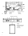
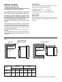
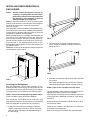
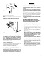
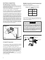
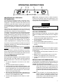
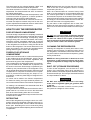
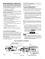
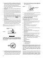
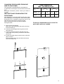
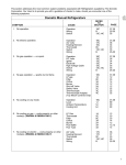
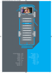
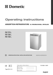
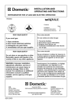
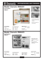
REFRIGERATORS AND FREEZERS
Model: Dometic RM4401
Part Number:
RM4401
• The internal fixing system is
standard and ensures easy
installation.
• Electronic re-ignition for
gas operation
Gross Capacity:
100 litres approx.
Freezer:
12 litres approx.
Weight: 29.5 kg approx.
Overall
Height:
Width:
Depth:
Dimensions:
805.5 mm
525 mm
536 mm
Electrical Input:
Electric: 240V - 135 Watts
12V - 130 Watts
Gas Input:
LP Gas: 18 g/hr
Model: Dometic RM2453
Part Number:
RM2453
• Wide metal mounting
flanges for built-in
application - no exterior
skin
• Door reversing kit
available, part number
2932750-02
Gross Capacity:
120 litres approx.
Freezer:
15 litres approx.
Weight: 41 kg approx.
Overall
Height:
Width:
Depth:
Dimensions:
948 mm
632 mm
627 mm
Recess
Height:
Width:
Depth:
Index
Required:
928 mm
602 mm
610 mm
Electrical Input:
Electric: 240V - 195 Watts
12V - 175 Watts
Gas Input:
LP Gas: 18 g/hr
INSTALLATION AND
OPERATING INSTRUCTIONS
REFRIGERATOR FOR LP-GAS AND ELECTRIC OPERATION
RA/RM-1D
RM 2453
RM 2553
Contents:
Installation
Operating Instructions
Maintenance & Service
FOR YOUR SAFETY
If you smell gas:
1. Open windows.
2. Don’t touch electrical switches.
3. Extinguish any open flame.
4. Immediately call your gas supplier.
FOR YOUR SAFETY
Do not store or use gasoline or other
flammable vapors and liquids in the
vicinity of this or any other appliance.
WARNING: Improper installation,
adjustment, alteration, service or
maintenance can cause injury or
property damage. Refer to this
manual. For assistance or additional
information consult a qualified
installer, service agency or the gas
supplier.
822 70 36-01
Page
3
7
9
Heaters
Cover,
Terminal block
Flue baffle
12 Volts
DC
12 Volts
DC
Heater
Reigniter
Protection
cover
Evaporation Tray
Screw for protection cover
12 volt terminal block
Inlet fitting
FIG. 1
Burner jet
Manual gas
shutoff valve
Flexible cord
Drain water hose
Refrigerator control panel
A
E
D
C
B
OFF
AC
OFF ON
FUEL SELECTOR
FLAME
PUSH WHEN LIGHTING
THERMOSTAT
LEGEND
A. ON/OFF, Fuel Selector Switch
B. Thermostat Knob, Gas/Electric
C. Flame Failure Safety Valve
Push-button
D. Piezo Igniter
E. Flame Indicator
FIG. 2
2
DATA PLATE
INSTALLATION
Check the data plate, inside the refrigerator, to ensure
that you have received the right model.
GENERAL INSTRUCTION
This appliance is designed for storage off foods and
storage of frozen foods and making ice.
This appliance must be installed by an authorised
person and conform to all relevant local authorities.
The appliance shall be installed in accordance with
the manufacturer’s installation instructions, local
gas fitting regulations, municipal building codes,
electrical wiring regulations, the AS 5601 Gas
Installations, and any other relevant statutory regulations.
The right gas pressure is ........... 2,7 kPa.
The right voltage is ........... 230 - 240 volt.
The data plate contains e.g. the following details:
Model designation ....................................
Product number ....................................
Serial number
....................................
Since these details will be needed if you have to contact
service personnel, it is a good idea to make a note of
them here.
The refrigerator must be installed on a solid floor and
must be level. With the vehicle carefully levelled, the refrigerator should level both ways in the freezer compartment. (More about levelling is to be found under the heading “Operating instructions”).
Free air circulation over the fins of the cooling unit is
essential.
In case detailed instructions on the installation and connection to the gas supply are required, contact your dealer
or distributor.
FIG. 3
Side view
NOTE: Wood Strip
MUST be in place
View from above
C
D
D
H
A
Overall
Dimensions
Refrigerator
Model
W
B
Recess
Dimensions
Height
A
Width
B
Depth
C
Height
H
Width
W
Depth
D
RM 2453
mm
948
632
627
928
602
610
RM 2553
mm
1104
632
627
1083
602
610
This methods of installation and these clearances will give you adequate space for service and proper installation.
3
INSTALLING REFRIGERATOR IN
ENCLOSURE
NOTE:
DO NOT install the appliance directly on
carpeting. Carpeting must be removed or
protected by a metal or wood panel beneath
the appliance, which extends at least full
width and depth of the appliance.
NOTE: A wood strip must be in place across the upper
opening of the enclosure. The top frame of the refrigerator will be anchored to the wood strip with screws.
See FIG. 3 page 3.
The refrigerator must be installed in a substantial enclosure and must be level. When installing the refrigerator
in the enclosure, all areas within the recess in which the
refrigerator is installed must be sealed.
Make sure that there is a complete seal between the
front frame of the refrigerator and the top, sides and
bottom of the enclosure. A length of sealing strip is applied to the rear surface of the front frame for this purpose, see FIG. 4. The sealing should provide a complete isolation of the appliance’s combustion system from
the vehicle interior.
NOTE: Be careful not to damage the sealing strip when
the refrigerator is put in place.
1
2
FIG. 5
2. Once the lower front strip is slipped under the
hinge, the part is possible to swing into place as
shown in FIG. 6.
3
FIG. 6
FIG. 4
Securing the Refrigerator
After the refrigerator is put in place, (ensuring a combustion seal at the front frame), the refrigerator is to be
secured in the enclosure with six screws (not included).
The screws have to be installed in the following order:
STEP 1: Two screws installed through the front base,
which includes the lower front strip installation.
The refrigerator is provided with a lower front strip
(shipped as a loose part). The front strip is to be attached
after the refrigerator is set into the cut-out opening.
1. Install the lower front strip by sliding it under the
bottom hinge plate, as shown in FIG. 5. The hinge
plate can be on the right or left side depending on
the door swing.
4
3. Secure the refrigerator and the lower front strip with
two screws:
One screw through the hinge, and on the opposite
side one screw through the lower front strip. (FIG. 6).
STEP 2: Two screws installed in the top frame.
The top decoration panel must be removed from the refrigerator before the screws can be installed.
Open the door and gently push the tabs out of the hole
in the hinge with a flat blade screwdriver, (both sides).
See FIG. 7.
Carefully tilt the top decoration panel and lift up to remove from top frame.
Install the two screws in the top frame, the holes are
accessible from underneath.
Seal the opening for the screws with aluminium tape.
! WARNING
DO NOT use a flame to check for gas leaks.
2
FIG. 7
1
Replace the top decoration panel.
Make sure the tabs snap back into the holes in the hinge
plate.
STEP 3: Two screws installed in the rear base.
See FIG. 8.
The gas supply system must incorporate an approved
gas pressure regulator to maintain a supply pressure of
2,75 kPa .
When testing the gas supply system at test pressures in
excess of 1/2 psi, the refrigerator and its individual shutoff
valve must be disconnected from the gas supply piping
system.
When testing the gas supply system at pressures less
than or equal to 1/2 psi, the appliance must be isolated
from the gas supply piping system by closing its individual manual shutoff valve.
In case detailed instructions on the installation and connection to the gas supply are required, contact your dealer
or distributor.
TESTING LP GAS SAFETY SHUTOFF
The gas safety shutoff must be tested after the refrigerator is connected to the LP gas supply.
FIG. 8
Failure to follow the sequence in securing the refrigerator
in the enclosure can cause leakage between the frame
and cabinet. Any space between the counter, storage
area or ceiling and top of the refrigerator greater than
40 mm should be blocked. The heat produced at the
rear of the refrigerator will become trapped in this space,
making the top of the refrigerator hot and reduce the
efficiency of the refrigerator.
LP GAS CONNECTION
The refrigerator is designed for operation on LP-gas, the
pressure of which must be 2,7 kPa for Propane.
Check that this is stated on the data plate.
To test the gas safety shutoff, proceed as follows:
1. Start the refrigerator according to the instructions for
LP Gas Operation. See section Operating Instructions.
2. Check that the gas flame is lit. This can be observed
on the flame indicator E. The red indicator is in the
green field, (ON).
3. Close the gas valve by turning the knob A back to
“OFF” position.
4. Wait for one minute.
5. Remove protection cover (see FIG. 1). Open the gas
valve by turning knob A to position “GAS” without
pushing the buttons C and D. Apply a non-corrosive
commercial bubble solution to the burner jet. Be careful not to damage the burner jet.
6. No bubbles should appear at the opening of the burner
jet. The presence of bubbles indicates a defective
gas safety shutoff, and service is required.
7. If no bubbles were present at the burner jet, the gas
safety valve is working properly. Rinse jet thoroughly
with fresh water before proceeding. Be careful not to
damage the burner jet.
Replace the protection cover and turn the main switch
OFF and back ON. See instruction for LP Gas Operation , section Operating Instructions. Normal operation of the burner should return. Allow the burner
to operate for a minimum of 5 minutes.
The refrigerator is not designed for operation on
town gas or natural gas.
Hook up to the gas supply line is accomplished at the
manual gas valve, which is furnished with a ISO 7/1 -Rp
1/8 internal pipe thread connection. All completed connections should be checked for leaks with soapy water.
5
ELECTRICAL CONNECTION
230-240 Volts AC Connection
The electrical installation must be carried out in a proper
and durable manner, taking into account all relevant regulations and codes of practice.
Check that the voltage stated on the data plate is the
same as the mains voltage in use (230-240V).
DO NOT use the chassis or vehicle frame as one of the
conductors. Connect two wires at the refrigerator and
route to the 12 V DC supply.
The refrigerator will draw 15 amps at 12 volt DC.
MAXIMUM TOTAL CONDUCTOR WIRE LENGTH
(in metre)
Wire length
For mains voltage operation, it is important that the
circuit to and in the caravan is effectively earthed.
The refrigerator is equipped with a three-prong (grounding) plug for your protection against shock hazards and
should be plugged directly into a properly grounded threeprong receptacle. DO NOT cut or remove the grounding
prong from this plug. The free length of the cord is 1.8 m
and therefore recommended that the receptacle be located to the left side of the refrigerator (viewed from the
rear) and approximately 150 mm from the floor. (See
FIG. 9). This allows easy access through the vent door.
The cord should be routed to avoid direct contact with
the burner cover, flue cover or any other components
that could damage the cord insulation.
230-240 Volt AC
receptacle
min.wire
size
5m
4 mm2
8m
6 mm2
The connections must be clean, tight and free from corrosion. If not, a resulting voltage drop will cause a decreased cooling capacity.
! CAUTION
DO NOT operate the refrigerator on 12 volt when
the vehicle is parked. The amperage draw of the
12-volt DC heating element can discharge a battery in a very short time. The installation of a 12volt DC operated refrigerator requires a relay to
be installed on the tow vehicle or in the caravan. The relay will automatically shut off the 12
volt DC power to the refrigerator when the ignition is turned off. (See FIG. below).
150 mm
FIG. 9
Switch key
Breaker Ignition
point
coil
Relay
Refrigerator
12 Volts DC Connection
The connection is made to the terminal block marked
“12 volts DC heater”, located at the bottom left corner on
the back of the refrigerator cabinet. (See FIG. 1).
The refrigerator must be connected to the battery circuit
with two wires of adequate capacity to avoid voltage drop.
The wire gauge should be chosen with consideration to
the wire length in accordance with the table below.
To ensure safe operation, the positive lead must be fitted with a fuse rated at 20 amps.
Correct polarity must be observed when connecting to
the 12 V DC supply.
6
Battery
OPERATING INSTRUCTIONS
A
E D
C
B
OFF
AC
OFF ON
FUEL SELECTOR
FLAME
PUSH WHEN LIGHTING
IMPORTANCE OF LEVELING A
REFRIGERATOR
In an absorption refrigerator system, ammonia is liquefied in the finned condenser coil at the top rear of the
refrigerator. The liquid ammonia then flows into the
evaporator (inside the freezer section) and is exposed
to a circulating flow of hydrogen gas, which causes the
ammonia to evaporate, creating a cold condition in the
freezer.
When starting this refrigerator for the very first time, the
cooling cycle may require up to four hours of running
time before the cooling unit is fully operational.
The tubing in the evaporator section is specifically sloped
to provide a continuous movement of liquid ammonia,
flowing downward by gravity through this section. If the
refrigerator is operated when it is not level and the vehicle is not moving, liquid ammonia will accumulate in
sections of the evaporator tubing. This will slow the circulation of hydrogen and ammonia gas, or in severe
cases, completely block it, resulting in a loss of cooling.
Any time the vehicle is parked for several hours with the
refrigerator operating, the vehicle should be leveled to
prevent this loss of cooling.
The vehicle needs to be leveled only so it is comfortable
to live in (no noticeable sloping of floor or walls).
When the vehicle is moving, the leveling is not critical,
as the rolling and pitching movement of the vehicle will
pass to either side of level, keeping the liquid ammonia
from accumulating in the evaporator tubing.
LP GAS OPERATION
Before starting the refrigerator, check that all the manual
gas valves are in the ON position. DO NOT forget the
manual shutoff valve on the rear of the refrigerator see
FIG. 1.
1. To start the refrigerator, turn knob A to the “GAS”
position.
2. Turn the thermostat knob B to position 4.
3. Push the button C in until it reaches the bottom - and
hold, push the button D for the piezo igniter several
times to light the burner. This can be observed on the
flame indicator E. When the flame is on, the red indicator is in the green field, (ON).
4. After the gas is lit keep the button C pressed for 10
seconds. Release the button and check that the RED
indicator is in the GREEN field, (ON).
5. To shut off the refrigerator turn the knob A to “OFF”
position.
THERMOSTAT
NOTE: After changing an LP tank, or after a long shutoff period, the gas line is likely to be filled with air. You
may have to repeat the lighting procedure several times
to purge the air out of the gas lines.
! WARNING
DO NOT OPERATE THE REFRIGERATOR ON
LP GAS WHILST TRAVELLING
230-240 V OPERATION
Before operating the refrigerator, check that the voltage
stated on the data plate is the same as main voltage in
use.
1. Check to be sure that the power cord is properly connected to the power supply. (See FIG. 9).
2. Turn the knob A to position marked “AC” for 230-240
volt AC operation.
3. Turn the thermostat knob B to position 4.
4. To shut off the refrigerator turn the knob A to “OFF”
position.
12 V OPERATION
Only operate your refrigerator on 12V when the engine
of the vehicle is running - otherwise your battery will soon
be discharged.
1. Turn the knob A to the position marked “DC” for 12
volts operation.
2. Note: there is no thermostat function on 12 V DC
operation, the refrigerator works continuously.
3. To shut off the refrigerator turn the knob A to “OFF”
position.
REGULATING THE TEMPERATURE
The refrigerator is equipped with a thermostat that can
be adjusted by turning the knob B to different setting to
maintain the desired cabinet temperature.
At OFF In gas operation, the thermostat closes its main
valve and the burner runs continuously at the
bypass rate, just enough to keep the burner lit.
In electrical operation, the contacts in the thermostat are open and the heating elements are
off.
At MAX In gas operation, the thermostat allows the
burner to remain on high flame continuously. In
electric operation, the heating element is “ON”
continuously. Lowest cabinet and freezer temperatures are obtained at this setting.
7
The thermostat can be adjusted between “MAX” and
“OFF” to obtain the desired cabinet temperature.
The closer the knob is to “MAX” - the colder the cabinet
temperature. The closer the knob is to “OFF” - the warmer
the cabinet temperature.
When the thermostat reaches the set temperature, it will
cut the burner back to bypass or, in electric operation,
(230-240 V AC) shut off the heating element.
The setting of the thermostat is not critical, but we recommend it be adjust to maintain a dry frost on the cooling fins. Adjust the thermostat knob closer to “MAX” when
the outside temperature becomes warm.
HOW TO USE THE REFRIGERATOR
FOOD STORAGE COMPARTMENT
The food storage compartment is completely closed and
unventilated, which is necessary to maintain the required
low temperature for food storage. Consequently, foods
having a strong odor or those that absorb odors easily
should be covered. Vegetables, salads etc. should be
covered to retain their crispness. The coldest positions
in the refrigerator are under the cooling fins and at the
bottom of the refrigerator. The warmer areas are on the
upper door shelves. This should be considered when
placing different types of food in the refrigerator.
FROZEN FOOD STORAGE
COMPARTMENT
Quick frozen soft fruits and ice cream should be placed
in the coldest part of the compartment, which is at the
bottom of the aluminum liner. Frozen vegetables, may
be stored in any part of the compartment.
This compartment is not designed for deep or quick freezing of food. Meat or fish, whether raw or prepared, can
be stored in the frozen food storage compartment provided they are precooled first in the refrigerator. They
can be stored about three times longer in the frozen food
compartment as compared to the fresh food compartment. To prevent food from drying out, keep it in covered dishes, containers, plastic bags or wrapped in aluminium foil.
Ice cubes can be made in the freezer compartment.
For faster ice making, the trays should be placed in direct contact with the bottom of the freezer compartment.
Ice making is accelerated if the thermostat knob B is
turned to the “MAX” setting.
It is a good idea to do this a few hours before the anticipated need for ice, but be sure to turn the thermostat
back to the normal setting when the ice is formed.
Food in the lower compartment may be frozen if the thermostat is left on “MAX”.
DEFROSTING
Shut off the refrigerator by turning the knob A to “OFF”
position. Empty the refrigerator, leaving the drip tray under the finned evaporator, and the cabinet and freezer
doors open. Defrosting time can be reduced by filling
the ice trays with hot water and placing them in the freezer
compartment.
8
NOTE: Defrost water runs from the drip tray to a receptacle at the rear of the refrigerator where it normally
evaporates. (See FIG. 1).
With a lot of defrost water as a result of heavy frosts
build up on the cooling fins, move the plastic drain tube
into a water tight bucket or container, (access through
louvered service panel on the outside of the vehicle).
When all frost has melted, wipe up the excess moisture
and empty the accumulated water from the bucket. Replace the drain tube to its original position.
Dry the interior of the refrigerator with a clean cloth.
Replace all food and set the thermostat to “MAX” for a
few hours, then reset the thermostat to its normal position.
! CAUTION
DO NOT use a hot air blower. Permanent damage
could result from warping the metal or plastic parts.
DO NOT use a knife or an ice pick, or other sharp
tools to remove frost from the freezer compartment.
They can create a leak in the ammonia system.
CLEANING THE REFRIGERATOR
Cleaning the refrigerator is usually done after it is defrosted or put into storage. To clean the interior liner of
the refrigerator, use lukewarm weak soda solution. Use
only warm water to clean the finned evaporator, gasket,
ice tray and shelves.
NEVER use strong chemicals or abrasives to clean
these parts, as the protective surfaces will be damaged. It is important to always keep the refrigerator
clean.
SHUT- OFF (STORAGE PROCEDURE)
To shut off the refrigerator, turn the knob A to “OFF”
position. If the refrigerator will not be in operation for a
period of weeks, it should be emptied, defrosted, cleaned
and the doors left ajar. The ice trays should also be dried
and kept outside the cabinet.
! WARNING
DO NOT store explosive substances in the refrigerator, such as cigarette lighter gas, gasoline, ether
or the like.
NOTE: Sodium chromate is used for corrosion protection (less than 2 weight % of the coolant).
MAINTENANCE & SERVICE
When replacing the refrigerator make sure that the sealing strips are properly positioned.
Replacement is the reverse of removal. Check all connections for gas leaks.
Refer to section INSTALLATION, page 2 to 6.
The user should be aware of service that must be
done on a regular schedule to keep the refrigerator
operating properly. The service should only be performed by a qualified technician who is familiar with
LP gas systems and refrigerators.
3. PERIODIC MAINTENANCE
1. CARTRIDGE HEATER
To keep your Dometic refrigerator operating efficiently
and safely, periodic inspection and cleaning of several
components once or twice a year is recommended.
The heat necessary for the operation of an absorption
cooling unit is supplied by an electric heater mounted in
a pocket of the boiler system.
Model RM 2453 and RM 2553 are equipped with two
electrical heaters, one for 230-240 volt AC and one for
12 volt DC.
To replace the heater proceed as follows:
1. Before working on the refrigerator make sure that
230-240 volt AC and optional 12 volt DC leads are
disconnected. Shut off Gas valve.
2. Remove the terminal block cover, see FIG. 1.
3. Disconnect the heater leads.
4. With a pair of pliers unfold the lug holding the lid of
the boiler casing and open the lid.
5. Remove some insulation wool so that the heater is
accessible.
6. Turn and lift the heater out of its pocket.
7. Fit the new heater into the pocket.
8. Connect the leads and put on the terminal block
cover.
9. Reset the insulation and close the lid of the boiler.
2. REFRIGERATOR REMOVAL
Before working on the refrigerator, make sure the AC
voltage and DC voltage leads are disconnected. Shut
off the gas supply at the LP tank. Disconnect the gas
supply line at the rear of the refrigerator, see FIG. 1.
Always use a back up wrench when loosening and tightening connections.
Cap the gas supply line, loosen the screws anchoring
the refrigerator to the enclosure and slide the refrigerator out of the compartment.
A. It is important to keep the area at the back of the
refrigerator clean. Check the lower vent, upper vent
and area between these openings for any obstructions such as bird/insect nests, spider webs, etc.
Clean the coils on the back of the refrigerator. Use a
soft bristled brush to dust off the coils.
It is important to keep the refrigerator area free from
combustible material, gasoline and other flammable
vapors or liquids.
NOTE: The following maintenance is required once or
twice a year, but should only be done by a qualified serviceman who is familiar with LP gas systems and refrigerators.
B. Check all connections in the LP gas system (at the
back of the refrigerator) for gas leaks. The LP gas
supply must be turned on. Apply a non-corrosive
bubble solution to all LP gas connections.
The appearance of bubbles indicates a leak and
should be repaired immediately by a QUALIFIED
SERVICEMAN WHO IS FAMILIAR WITH GAS SYSTEM AND REFRIGERATORS.
! WARNING
DO NOT use a flame to check for gas leaks.
C. The LP gas pressure should be checked and the main
regulator readjusted if pressure is incorrect. The correct operating pressure is 2,7 kPa. The correct place
to take the LP gas pressure is at the test port just
ahead of the burner jet. (See FIG. 10).
GAS EQUIPMENT ASSEMBLY
MANUAL SHUT OFF VALVE
Shown in open position
Use a slotted screwdriver to change position
INLET FITTING
NUT
THERMOCOUPLE
SPARK ELECTRODE
PRESSURE TEST PORT
BURNER TUBE
FIG. 10
BURNER JET
BURNER MOUNTING SCREW
9
D. Inspect the flue baffle. It should be reasonably clean
and free of soot. Heavy soot formation indicates improper functioning of the burner. The flue and burner
both require cleaning in the following manner:
1. Unplug the refrigerator power cord from the 230-240
volt AC outlet. (See FIG. 9).
2. Disconnect or shut off the 12 volt DC power to the
refrigerator.
3. Turn manual shutoff valve to OFF. (See FIG. 1 & 10).
4. Remove cover from the burner housing. (See FIG. 1).
5. Disconnect the wire from the high voltage electrode.
6. Remove the burner mounting screw and remove the
burner assembly. (See FIG. 10).
7. Remove the wire and flue baffle from the top of flue
tube. Clean the flue from the top using a flue brush.
Blowing compressed air into the flue will not properly
clean soot and scale out of the flue tube. Replace the
flue baffle.
8. Clean burner tube with a brush. Blow out burner with
compressed air.
9. Before removing burner jet, clean burner area of soot
and scale that fell out of flue tube. Remove the burner
jet. Soak the jet in wood alcohol and blow it out with
compressed air. Reinstall and tighten burner jet.
NOTE: The colour of the flame shall be clear blue over
the slots of the burner. (See FIG. 11).
Clear blue colour
of flame
FIG. 11
! WARNING
DO NOT use a wire or pin when cleaning the burner
jet as damage can occur to the precision opening.
This can cause damage to the refrigerator or create
a fire hazard.
11. Be sure to reconnect the wire to high voltage electrode. Check the electrode for proper location and
gap. (See FIG. 12).
FIG. 12
Electrode
1/8” to 3/16”
(3-5 mm)
Burner tube
12. Turn on manual gas shutoff valve and check all fittings for leaks with soapy water.
13. Connect 230-240 volt power cord to the outlet and
reconnect or turn on the 12 volt DC power.
14. Check LP gas safety shutoff. See page 5.
4. TROUBLESHOOTING
Refrigerator Does Not Cool Properly
A. Burner jet clogged.
Clean. (See section Maintenance & Service, item 3.
Periodic maintenance, Paragraph D. item 1-14).
B. Check level of refrigerator.
C. Venting problem.
Restriction in air flow across cooling unit.
D. Heavy frost buildup on evaporator fins.
Defrost.
E. Flue baffle not inserted properly in flue tube. (See
page 2, FIG. 1)
F. Improperly set thermostat.
(See Operating Instructions, part Regulating the
temperature).
G. Burner dirty.
Clean. (See section Maintenance & Service, item 3.
Periodic Maintenance, Paragraph D. item 1-14).
H. LP gas pressure low at burner.
Set main regulator so pressure does not drop
below 2,7 kPa at pressure test port. (See FIG. 10).
I. Burner not located properly under flue tube.
Relocate
J. Burner damaged.
Replace
K. Odor from fumes.
1. Dislocated burner
2. Damaged burner
3. Dirty flue tube
NOTE: AVOID SPRAYING WATER THROUGH THE
REFRIGERATOR VENTS WHILE WASHING YOUR RV.
The sealed cooling system must not be opened,
since it contains corroding chemicals under high
pressure.
10. Reinstall burner, being careful that the end of the
burner fits into the slot on the burner bracket. Check
to make sure slots are centered under the flue tube
and the thermocouple is positioned properly (tip of
thermocouple extends over two slots of burner).
10
All the above instructions are to be followed closely. The
refrigerator is quality-guaranteed. However, we are not
responsible for any failures caused by improper adjustments and unfavorable installation conditions. Contact
service point or distributor service dept. for assistance.
CHANGING DOOR HINGES FROM ONE
SIDE TO THE OTHER
The refrigerator is equipped with a reversible door.
A special door reversing kit must be used to reverse the
door.
For further information, please contact your dealer or
Dometic.
INSTRUCTIONS FOR MOUNTING THE
DOOR PANEL
The refrigerator is normally delivered with door panel.
Before starting the mounting work, check that the panel
dimensions are in compliance with those given in the
table and the instructions are read thoroughly.
When mounting the panel, proceed as follows:
See figure below.
A. Open the door 90 degrees.
Remove the door decoration strip (2) by removing
its three screws (1).
B. Insert the vertical edges into the grooves of the
door frame (3).
C. Push the panel downward so that the lower horizontal edge of the panel (4) is fitted into the bottom
groove (5).
D. Put the decoration strip across the door so that the
gap is covered.
Secure the decoration strip with the three screws
removed in Step A (1).
REFR. MODEL
TYPE
HEIGHT
MAX.
MIN.
WIDTH
MAX.
MIN.
RM 2453
mm
827
825
527
524
RM 2553
mm
983
981
527
524
Contact an authorized service center for
parts and repairs as needed.
1
1
1
PANEL DIMENSIONS
MAX. THICKNESS (4 mm)
2
3
3
1
1
1
4
5
11
RM 2453 RM 2553
MO-FO 0325
12