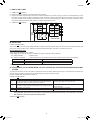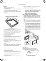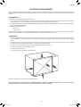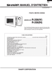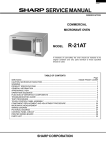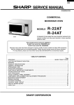
1
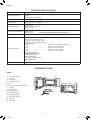
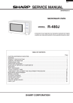
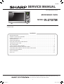
R-27STM
SERVICE MANUAL
No. S0801R27STPKS
STIR TURN KG PCS
MICROWAVE OVEN
MODEL
R-27STM
In interests of user-safety the oven should be restored to its original condition and only parts identical to those specified
should be used.
CONTENTS
BEFORE SERVICING - - - - - - - - - - - - - - - - - - - - - - - - - - - - - - - - - - - - - - - - - - - - - - - - - - - - - - - - - - - - - - - - - - - 2
WARNING TO SERVICE PERSONNEL- - - - - - - - - - - - - - - - - - - - - - - - - - - - - - - - - - - - - - - - - - - - - - - - - - - - - - - 3
PRODUCT SPECIFICATIONS - - - - - - - - - - - - - - - - - - - - - - - - - - - - - - - - - - - - - - - - - - - - - - - - - - - - - - - - - - - - - 4
APPEARANCE VIEW- - - - - - - - - - - - - - - - - - - - - - - - - - - - - - - - - - - - - - - - - - - - - - - - - - - - - - - - - - - - - - - - - - - - 4
OPERATION SEQUENCE - - - - - - - - - - - - - - - - - - - - - - - - - - - - - - - - - - - - - - - - - - - - - - - - - - - - - - - - - - - - - - - - 5
FUNCTION OF IMPORTANT COMPONENTS- - - - - - - - - - - - - - - - - - - - - - - - - - - - - - - - - - - - - - - - - - - - - - - - - - 6
TROUBLESHOOTING GUIDE - - - - - - - - - - - - - - - - - - - - - - - - - - - - - - - - - - - - - - - - - - - - - - - - - - - - - - - - - - - - - 7
TEST PROCEDURES - - - - - - - - - - - - - - - - - - - - - - - - - - - - - - - - - - - - - - - - - - - - - - - - - - - - - - - - - - - - - - - - - - - 8
TOUCH CONTROL PANEL ASSEMBLY - - - - - - - - - - - - - - - - - - - - - - - - - - - - - - - - - - - - - - - - - - - - - - - - - - - - - 12
PRECAUTIONS FOR USING LEAD-FREE SOLDER - - - - - - - - - - - - - - - - - - - - - - - - - - - - - - - - - - - - - - - - - - - - 13
COMPONENT REPLACEMENT AND ADJUSTMENT PROCEDURE- - - - - - - - - - - - - - - - - - - - - - - - - - - - - - - - - 14
MICROWAVE MEASUREMENT- - - - - - - - - - - - - - - - - - - - - - - - - - - - - - - - - - - - - - - - - - - - - - - - - - - - - - - - - - - 19
CIRCUIT DIAGRAMS- - - - - - - - - - - - - - - - - - - - - - - - - - - - - - - - - - - - - - - - - - - - - - - - - - - - - - - - - - - - - - - - - - - 20
PARTS LIST - - - - - - - - - - - - - - - - - - - - - - - - - - - - - - - - - - - - - - - - - - - - - - - - - - - - - - - - - - - - - - - - - - - - - - - - - 24
This document has been published to be used for after sales service only.
The contents are subject to change without notice.
1
R27STM.indd 1
11/3/08 2:04:24 PM
R-27STM
BEFORE SERVICING
GENERAL IMPORTANT INFORMATION
This Manual has been prepared to provide Sharp Corp. Service engineers with Operation and Service Information.
It is recommended that service engineers carefully study the entire text of this manual, so they will be qualified to render satisfactory
customer service.
WARNING: THIS APPLIANCE MUST BE EARTHED
IMPORTANT
THE WIRES IN THIS MAINS LEAD ARE COLOURED IN ACCORDANCE WITH THE FOLLOWING CODE:
GREEN-AND-YELLOW-------------------------------- EARTH
BLUE--------------------------------------------------- NEUTRAL
BROWN--------------------------------------------------------LIVE
CAUTION MICROWAVE RADIATION
DO NOT BECOME EXPOSED TO RADIATION FROM THE MICROWAVE GENERATOR OR OTHER PARTS CON DUCTING MICROWAVE ENERGY.
Service engineers should not be exposed to the microwave energy which may radiate from the magnetron or other
microwave generating devices if it is improperly used or connected. All input and output microwave connections,
waveguides, flanges and gaskets must be secured. Never operate the device without a microwave energy absorbing
load attached. Never look into an open waveguide or antenna while the device is energized.
WARNING
Never operate the oven until the following points are ensured.
(A) The door is tightly closed.
(B) The door brackets and hinges are not defective.
(C) The door packing is not damaged.
(D) The door is not deformed or warped.
(E) There is not any other visible damage with the oven.
Servicing and repair work must be carried out only by trained service engineers.
All the parts marked "∆" on parts list are used at voltage more than 250V.
Removal of the outer wrap gives access to potential above 250V.
All the parts marked "*" on parts list may cause undue microwave exposure, by themselves, or when they are damaged,
loosened or removed.
2
R27STM.indd 2
11/3/08 2:04:24 PM
R-27STM
WARNING TO SERVICE PERSONNEL
Microwave ovens contain circuitry capable of producing very high voltage and current, contact with any part of the high voltage circuit
will result in electrocution. High voltage capacitor, Power transformer, Magnetron, High voltage rectifier assembly, High voltage fuse,
High voltage harness.
REMEMBER TO CHECK 3D
REMEMBER TO CHECK 4R
Disconnect the supply.
Door opened, and wedged open.
Reconnect all leads removed from components during testing.
Discharge the high voltage capacitor.
Replace the outer case (cabinet).
WARNING:AGAINST THE CHARGE OF THE HIGH-VOLTAGE CAPACITOR
Reconnect the supply.
Run the oven. Check all functions.
The high-voltage capacitor remains charged about 60
seconds after the oven has been switched off. Wait for
60 seconds and then short-circuit the connection of the
high-voltage capacitor (that is, of the connecting lead of
the high-voltage rectifier) against the chassis with the
use of an insulated screwdriver.
Microwave ovens should not be run empty. To test for the
presence of microwave energy within a cavity, place a cup of
cold water on the oven turntable, close the door and set the
power level to HIGH (100%). And set the microwave timer for
two (2) minutes. When the two minutes has elapsed (timer at
zero) carefully check that the water is now hot. If the water re mains cold, carry out 3D checks and re-examine the connec tions to the component being tested.
Sharp recommend that wherever possible fault-finding is car ried out with the supply disconnected. It may, in some cases,
be necessary to connect the supply after the outer case has
been removed, in this event carry out 3D checks and then
disconnect the leads to the primary of the power transformer.
Ensure that these leads remain isolated from other compo nents and the oven chassis. (Use insulation tape if neces sary.) When the testing is completed, carry out 3D checks and
reconnect the leads to the primary of the power transformer.
When all service work is completed and the oven is fully assembled, the microwave power output should be checked and microwave
leakage test should be carried out.
3
R27STM.indd 3
11/3/08 2:04:24 PM
R-27STM
PRODUCT SPECIFICATIONS
ITEM
DESCRIPTION
Power Requirements
230 - 240 Volts
50 Hertz
Single phase, 3 wire earthed
Power Consumption
1.22 kW
Power Output
800 watts nominal of RF microwave energy (IEC60705 Test Procedure)
Operating frequency 2450 MHz
Outside Dimensions
Width 460 mm
Height 275 mm including foot
Depth 370 mm
Cooking Cavity Dimensions
Width 319 mm
Height 215 mm
Depth 336 mm
Turntable diameter
272 mm
Control Complement
Touch Control System
Timer (0 - 99 minutes 90 seconds)
Clock (1:00 - 12:59) or (0:00 - 23:59)
Microwave Power for Variable Cooking
Repetition Rate;
100P ....................................................... Full power throughout the cooking time
70P .........................................................approx. 70% of FULL Power
50P ....................................................... approx. 50% of FULL Power
30P ........................................................approx. 30% of FULL Power
10P .........................................................approx. 10% of FULL Power
EXPRESS COOK button
EXPRESS DEFROST button
POWER LEVEL button
STOP/CLEAR button
START/AUTO MINUTE button
TIME/WEIGHT knob
Set Weight (Approx.)
12 kg
NOTE: Internal capacity is calculated by measuring maximum width, depth
and height. Actual capacity for holding food is less.
APPEARANCE VIEW
OVEN
6
1. Door opening handle
2
2. Oven lamp
3. Door hinges
4. Door safety latches
1
3
9
5. Door
11
6. Door seals and sealing surfaces
9. Control panel
7
8
7. Coupling
4
10 4
5
10. Waveguide cover
14
11. Power supply cord
15
12.Ventilation openings
13
12
13.Outer case cabinet
14.Turntable
15. Roller stay
4
R27STM.indd 4
11/3/08 2:04:25 PM
R-27STM
TOUCH CONTROL PANEL
1. DIGITAL DISPLAY
1
2. INDICATORS
STIR TURN KG PCS MICRO COOK
2
BUTTONS:
3. AUTO COOK
3
4. EXPRESS COOK
5. EXPRESS DEFROST
6. START/AUTO MINUTE
7. STOP/CLEAR
4
8. POWER LEVEL
9. TIME/WEIGHT KNOB
5
NOTE:Some one-touch cooking features such as "START/AUTO MINUTE" are
disabled after three minutes when the oven is not in use. These features are automatically enabled when the door is opened and closed
or the STOP button is pressed.
6
7
8
9
OPERATION SEQUENCE
through the waveguide (transport channel) into the oven cavity,
where the food is placed to be cooked.
OFF CONDITION
Closing the door activates all door interlock switches (1st. latch
switch, 2nd. interlock relay control switch).
When the cooking time is up, a signal tone is heard and the re lays (RY1+RY2) go back to their home position. The circuits to
the oven lamp, high voltage transformer, fan motor and turntable
motor are cut off.
IMPORTANT
When the oven door is closed, the monitor switch contacts
(COM-NC) must be open.
When the door is opened during a cook cycle, the switches
come to the following condition
When the microwave oven is plugged in a wall outlet, rated volt age is supplied to the noise filter and the control unit.
Figure O-1 on page 20
SWITCH
The display will show flashing "88:88".
To set any programmes or set the clock, you must first touch the
STOP/CLEAR button.
" : " appears in the display.
MICROWAVE COOKING CONDITION
Enter a desired cooking time by rotating the TIME/WEIGHT
knob and start the oven with pressing START/AUTO MINUTE
button.
1st. latch switch
COM-NO
Closed
Open
2nd. interlock relay
control switch
COM-NO
Closed
Open
Monitor switch
COM-NC
Open
Closed
MONITOR SWITCH CIRCUIT
The monitor switch is mechanically controlled by oven door, and
monitors the operation of the 1st. latch switch, the relay (RY1)
and the 2nd. interlock relay (RY2).
Function sequence
Figure O-2 on page 20
CONNECTED COMPONENTS
CONDITION
DURING
DOOR OPEN
COOKING
(NO COOKING)
The circuits to the high voltage transformer, fan motor, turntable
motor and oven lamp are cut off when the 1st. latch switch and
2nd. interlock relay control switch are made open.
HIGH COOKING
Oven lamp, Fan motor, Turntable motor
High voltage transformer
CONTACT
RELAY
When the oven door is opened during or after the cycle of a
cooking program, the 1st. latch switch and 2nd. interlock relay
control switch must open their contacts first. After that the con tacts (COM-NC) of the monitor switch can be closed.
RY1
RY2
Rated voltage is supplied to the primary winding of the high volt age transformer. The voltage is converted to about 3.3 volts A.C.
output on the filament winding and high voltage of approximately
2000 volts A.C. on the secondary winding
When the oven door is closed, the contacts (COM-NC) of the
monitor switch must be opened. After that the contacts of the
1st. latch switch and 2nd. interlock relay control switch are
closed.
The filament winding voltage (3.3 volts) heats the magnetron
filament and the high voltage (2000 volts) is sent to the voltage
doubling circuit, where it is doubled to negative voltage of ap proximately 4000 volts D.C..
When the oven door is opened and the contacts of the 1st. latch
switch, the relay (RY1) and the 2nd. interlock relay (RY1) remain
closed. The fuse T6.3A will blow, because the monitor switch is
closed and a short circuit is caused.
The 2450 MHz microwave energy produced in the magnetron
generates a wave length of 12.24 cm. This energy is channelled
5
R27STM.indd 5
11/3/08 2:04:25 PM
R-27STM
NOTE:The ON/OFF time ratio does not exactly correspond
to the percentage of microwave power, because approx. 3 seconds are needed for heating up the magnetron filament.
MEDIUM HIGH, MEDIUM, MEDIUM LOW, LOW
COOKING
When the microwave oven is preset for variable cooking power,
rated voltage is supplied to the high voltage transformer inter mittently within a 32 second time base through the relay contact
which is coupled with the current-limiting relay (RY2). The fol lowing levels of microwave power are given.
SETTING;
POWER OUTPUT REDUCTION
After 100% power cooking mode is carried out for more than
20 minutes, the power out-put is automatically reduced to 70%.
Even if the cooking time is shorter than for 20 minutes, the
power output is reduced to 70% after total cooking time over 20
minutes when the oven is started in 100% power cooking mode
again within 1 minute and 35 seconds.
32 sec. ON
100P (HIGH)
100%
24 sec. ON
8 sec. OFF
18 sec. ON
14 sec. OFF
12 sec. ON
20 sec. OFF
6 sec. ON
26 sec. OFF
70P (MEDIUM
HIGH)
Approx. 70%
50P (MEDIUM)
30P (MEDIUM
LOW)
Approx. 50%
Approx. 30%
10P (LOW)
Approx. 10%
FUNCTION OF IMPORTANT COMPONENTS
FUSE T6.3A
Latch Heads
111 The fuse T6.3A blows when the contacts (COM-NO) of the 1
st. latch switch, the relay (RY1) and the 2nd. interlock relay
(RY2) remain closed with the oven door open and when the
monitor switch closes.
Latch Hook
2nd. Interlock Relay
Control Switch
222 If the wire harness or electrical components are shortcircuited, the fuse T6.3A blows to prevent an electric shock
of fire hazard.
Monitor Switch
HIGH VOLTAGE FUSE
Door
The high voltage fuse blows when the high voltage rectifier or
the magnetron is shorted.
1st. Latch Switch
DOOR OPEN MECHANISM
TEMPERATURE FUSE 150°C (OVEN)
The door is opened by pulling the door, refer to the Figure D-1.
111 When the oven door is closed, the contacts (COM-NO) must
be closed.
The temperature fuse located on the top of the oven cavity is
designed to prevent damage to the oven if the foods in the oven
catch fire due to over heating produced by improper setting
of cook time or failure of control unit. Under normal operation,
the temperature fuse remains closed. However, when abnor mally high temperatures are reached within the oven cavity, the
temperature fuse will open at 150°C, causing the oven to shut
down. The defective temperature fuse must be replaced with a
new one.
222 When the oven door is opened, the contacts (COM-NO)
must be opened.
TURNTABLE MOTOR
Figure D-1. Door Open Mechanism
1ST. LATCH SWITCH AND 2ND. INTERLOCK RELAY CONTROL SWITCH
MONITOR SWITCH
The turntable motor drives the turntable roller assembly to ro tate the turntable.
111 When the oven door is closed, the contacts (COM-NC) must
be opened.
FAN MOTOR
222 When the oven door is opened, the contacts (COM-NC)
must be closed.
The fan motor drives a blade which draws external cool air. This
cool air is directed through the air vanes surrounding the mag netron and cools the magnetron. This air is channelled through
the oven cavity to remove steam and vapours given off from the
heating foods. It is then exhausted through the exhausting air
vents at the oven cavity.
333 If the oven door is opened and the contacts (COM-NO) of
the 1st latch switch, the relay (RY1) and the 2nd. interlock
relay (RY2) fail to open, the fuse T6.3A blows simultaneous ly with closing the contacts (COM-NC) of the monitor switch.
CAUTION:BEFORE REPLACING A FUSE T6.3A TEST THE
1ST. LATCH SWITCH, RELAY (RY1) AND 2ND. IN TERLOCK RELAY (RY2) AND MONITOR SWITCH
FOR PROPER OPERATION. (REFER TO CHAP TER "TEST PROCEDURE".)
NOISE FILTER
The noise filter prevents the radio frequency interference that
might flow back in the power circuit.
6
R27STM.indd 6
11/3/08 2:04:26 PM
R-27STM
TROUBLESHOOTING GUIDE
FOREWORD
IMPORTANT:
When troubleshooting the microwave oven, it is helpful to follow
the Sequence of Operation in performing the checks. Many of
the possible causes of trouble will require that a specific test be
performed. These tests are given a procedure letter which will
be found in the "Test Procedure" section.
If the oven becomes inoperative because of a blown fuse T6.3A
in the 1st. latch switch - relay (RY1) - 2nd. interlock relay (RY2)monitor switch circuit, check the 1st. latch switch, relay (RY1),
2nd. interlock relay (RY2) and monitor switch before replacing
the fuse T6.3A.
POSSIBLE CAUSE
AND
DEFECTIVE PARTS
CONDITION
PROBLEM
CK
D E E E F G G H K M M N RE CK CK RE CK CK CK CK CK I L J
MAGNETRON
HIGH VOLTAGE TRANSFORMER
H.V. RECTIFIER ASSEMBLY
HIGH VOLTAGE WIRE
HIGH VOLTAGE CAPACITOR
1ST. LATCH SWITCH
2ND. INTERLOCK RELAY CONTROL
SWITCH
MONITOR SWITCH
TEMPERATURE FUSE 150ºC (OVEN)
FAN MOTOR
TURNTABLE MOTOR
FUSE T6.3A
TOUCH CONTROL PANEL
RELAY (RY-1)
RELAY (RY-2)
FOIL PATERN ON P.W.B.
POWER SUPPLY CORD
SHORTED WIRE HARNESS
OPENED WIRE HARNESS
OVEN LAMP
WALL OUTLET
MISADJUSTMENT SWITCH
HOME FUSE OR BREAKER
BLOCKED COOLING FAN
BLOCKED VENTILATION
NOISE FILTER
SWITCH UNIT
H.V. FUSE
TEST PROCEDURE A B C
Home fuse blows when powersupply cord is plugged into
wall outlet.
FUSE T6.3A blows when
power supply cord is plugged into wall outlet.
OFF
CONDITION
"88:88" does not appear in
display but power supply cord
is plugged into wall outlet.
Display does not operate
properly when STOP/CLEAR
button is pressed.
Oven does not start when the
START button is touched.
(Display appears)
Oven lamp does not light
(Display appears.)
Fan motor does not operate.
(Display appears.)
Turntable motor does not
operate. (Display appears.)
Oven or any electrical parts
does not stop when cooking
time is 0 or STOP button is
pressed.
ON
CONDITION
Oven seems to be operating
but little or no heat is produced in oven load. (Microwave power level is set at
100%)
Oven does not seems to be
operating properly when
70%,50%, 30% or 10% is
set. (Oven operates properly
at 100%.)
Oven goes into cook cycle
but shuts down before end
of cooking cycle.
7
R27STM.indd 7
11/3/08 2:04:26 PM
R-27STM
TEST PROCEDURES
A: MAGNETRON TEST
NEVER TOUCH ANY PART IN THE CIRCUIT WITH YOUR HAND OR AN INSULATED TOOL WHILE THE OVEN IS
IN OPERATION.
111 CARRY OUT 3D CHECKS.
222 To test for an open filament, isolate the magnetron from the high voltage circuit. A continuity check across the magnetron filament
leads should indicate less than 1 ohm.
333 To test for a shorted magnetron, connect the ohmmeter leads between the magnetron filament leads and chassis ground. This test
should indicate an infinite resistance. If there is little or no resistance the magnetron is grounded and must be replaced.
444 Reconnect all leads removed from components during testing.
555 Reinstall the outer case (cabinet).
666 Reconnect the power supply cord after the outer case is installed.
777 Run the oven and check all functions.
MICROWAVE OUTPUT POWER
The following test procedure should be carried out with the microwave oven in a fully assembled condition (outer case fitted).
The power output of this oven is rated using the method specified by IEC 60705. Full details of how to curry out this procedure can be
found in the Sharp Technical Training notes which is available from Sharp Parts Centre (part number SERV-LITMW01).
The IEC60705 procedure must be carried out using laboratory-type procedures and equipment.
These requirements make the procedure unsuitable for routine performance checks.
NOTE:The following test method gives an indication of the output power only, it cannot be used to establish the actual/rated
output power. If the true output power is required, then the IEC 60705 test method must be used.
Alternative simplified method:
111 Place 2 litres of cold water (between 12ºC and 20ºC) in a suitable container.
222 Stir the water and measure the temperature in ºC. Note temperature as T1.
333 Place the container in the microwave and heat the water for 1 minute and 48 seconds on full power.
NOTE:The operation time of microwave oven includes "3" sec. (3 sec. is magnetron filament heat-up time.)
444 When the 1 minute and 48 seconds is completed, remove the container and stir the water. Note the water temperature as T2.
555 Calculate the output power using the following formula:
R.F. Power Output = (T2 - T1) x 80.
NOTE:The result from this test should be within the allowance of 2000cc alternative method. (±10%).
MICROWAVE LEAKAGE TEST
This oven should be tested for microwave leakage on completion of any repair or adjustment, following the procedure described in
the Sharp Technical Training notes (part number SERV-LITMW01). The maximum leakage permitted in BS EN 60335-2-25 is 50W/m2
(equivalent to 5W/m2), however it is not normal to detect any significant leakage, therefore, any leakage which is detected should be
investigated.
It is essential that only leakage detectors with current calibration traceable to National Physical Laboratories are used.
Suitable leakage detectors: CELTEC A100
APOLLO X1
B: HIGH VOLTAGE TRANSFORMER TEST
WARNING:High voltage and large currents are present at the secondary winding and filament winding of the power transformer. It is very dangerous to work near this part when the oven is on. NEVER make any voltage measurements of the high-voltage circuits, including the magnetron filament.
111 CARRY OUT 3D CHECKS.
222 Disconnect the leads to the primary winding of the high voltage transformer. Disconnect the filament and secondary winding con nections from the rest of the HV circuitry. Using an ohmmeter, set on a low range, it is possible to check the continuity of all three
winding. The following readings should be obtained:
a. Primary winding- - - - - - - - - - 2.8 ohms approximately
b. Secondary winding- - - - - - - 204 ohms approximately
c. Filament winding - - - - - - - - - - - - - - - less than 1 ohm
If the readings obtained are not stated as above, then the high voltage transformer is probably faulty and should be replaced.
333 Also, the high voltage transformer has the thermal cut-out in the primary coil. The thermal cut-out will open when the temperature
of the thermal cut-out in the primary coil reaches approximately 150ºC. The thermal cut-out resets automatically at 130°C. If an
ohmmeter indicates an open circuit under normal condition, replace the high voltage transformer because the primary coil (thermal
cut-out) has opened. An open primary coil (thermal cut-out) indicates overheating of the high voltage transformer. Check for re stricted air flow to the high voltage transformer, especially the ventilation opening.
8
R27STM.indd 8
11/3/08 2:04:26 PM
R-27STM
444 CARRY OUT 4R CHECKS.
C: HIGH VOLTAGE RECTIFIER TEST
CARRY OUT 3D CHECKS.
Isolate the high voltage rectifier assembly from the HV circuit. The high voltage rectifier can be tested using an ohmmeter set to its
highest range. Connect the ohmmeter across the terminal of the high voltage rectifier and note the reading obtained. Reverse the me ter leads and note this second reading. The normal resistance is infinite in one direction and more than 100 kW in the other direction.
CARRY OUT 4R CHECKS.
NOTE:FOR MEASUREMENT OF THE RESISTANCE OF THE RECTIFIER, THE BATTERIES OF THE MEASURING
INSTRUMENT MUST HAVE A VOLTAGE AT LEAST 6 VOLTS, BECAUSE OTHERWISE AN INFINITE RESISTANCE MIGHT BE SHOWN IN BOTH DIRECTION.
D: HIGH VOLTAGE CAPACITOR TEST
CARRY OUT 3D CHECKS.
111 Isolate the high voltage capacitor from the circuit.
222 Continuity check must be carried out with measuring instrument which is set to the highest resistance range.
333 A normal capacitor shows continuity for a short time (kick) and then a resistance of about 10MW after it has been charged.
444 A short-circuited capacitor shows continuity all the time.
555 An open capacitor constantly shows a resistance about 10 MW because of its internal 10MW resistance.
666 When the internal wire is opened in the high voltage capacitor shows an infinite resistance.
777 The resistance across all the terminals and the chassis must be infinite when the capacitor is normal.
If incorrect reading are obtained, the high voltage capacitor must be replaced.
CARRY OUT 4R CHECKS.
E: SWITCH TEST
CARRY OUT 3D CHECKS.
Isolate the switch to be tested and using an ohmmeter check between the terminals as described in the following table.
Table: Terminal Connection of Switch
Plunger Operation
Common terminal to Normally open terminal Common terminal to Normally close terminal
Released
Open circuit
Short circuit
Depressed
Short circuit
Open circuit.
If incorrect readings are obtained, make the necessary switch adjustment or replace the switch.
CARRY OUT 4R CHECKS.
F: TEMPERATURE FUSE TEST
CARRY OUT 3D CHECKS.
Disconnect the leads from the terminals of the temperature fuse. Then using an ohmmeter, make a continuity test across the two ter minals as described in the below.
Table: Temperature Fuse Test
Parts Name
Temperature of "ON" condition
(Closed circuit).
Temperature of "OFF" condition
(Open circuit).
Indication of ohmmeter
(When room temperature is approx. 20°C.)
Temperature fuse 150°C
This is not resetable type.
Above 150°C
Closed circuit
If incorrect readings are obtained, replace the temperature fuse.
An open circuit temperature fuse (OVEN) indicates that the food in the oven cavity may catch fire, this may be due to overheating pro duced by improper setting of the cooking time or failure of the control panel.
CARRY OUT 4R CHECKS.
G: MOTOR WINDING TEST
CARRY OUT 3D CHECKS.
Disconnect the leads from the motor. Using an ohmmeter, check the resistance between the two terminals as described in the table
below.
Table: Resistance of Motor
Motors
Fan motor
Turntable motor
Resistance
Approximately 250 W
Approximately 14.7 kW
If incorrect readings are obtained, replace the motor. CARRY OUT 4R CHECKS.
9
R27STM.indd 9
11/3/08 2:04:26 PM
R-27STM
H: FUSE T6.3A
CARRY OUT 3D CHECKS.
If the fuse T6.3A is blown when the door is opened, check the 1st. latch switch, relay (RY1), 2nd. interlock relay (RY2) and monitor
switch.
If the fuse T6.3A is blown by incorrect door switching replace the defective switch(es) and the fuse T6.3A.
If the fuse T6.3A is blown, there is a shorts or grounds in electrical parts or wire harness. Check them and replace the defective parts
or repair the wire harness.
CARRY OUT 4R CHECKS.
CAUTION:ONLY REPLACE FUSE T6.3A WITH THE CORRECT VALUE REPLACEMENT.
I: NOISE FILTER TEST
NOISE FILTER
L
N
CARRY OUT 3D CHECKS.
FUSE
T6.3A
Disconnect the leads from the terminals of the noise filter. Using an ohmme ter, check between the terminals as described in the following table.
MEASURING POINT
Between N and L
Between terminal N and WHITE
Between terminal L and RED
INDICATION OF OHMMETER
Open circuit
Short circuit
Short circuit
NOISE SUPPRESSION COIL
If incorrect readings are obtained, replace the noise filter unit.
CARRY OUT 4R CHECKS.
WHT
RED
J: HIGH VOLTAGE FUSE TEST
CARRY OUT 3D CHECKS.
If the high voltage fuse is blown, there could be a short in the high voltage rectifier or the magnetron.
Check them and replace the defective parts and the high voltage fuse.
CARRY OUT 4R CHECKS.
CAUTION:ONLY REPLACE HIGH VOLTAGE FUSE WITH THE CORRECT VALUE REPLACEMENT.
K: TOUCH CONTROL PANEL ASSEMBLY TEST
The touch control panel consists of circuits including semiconductors such as LSI, ICs, etc. Therefore, unlike conventional microwave
ovens, proper maintenance cannot be performed with only a voltmeter and ohmmeter. In this service manual, the touch control panel
assembly is divided into two units, Control Unit and Switch Unit, and also the Control Unit is divided into two units, CPU Unit and Pow er Unit, and troubleshooting by unit replacement is described according to the symptoms indicated.
1. Switch Unit. Note: Check switch unit wire harness connection before replacement.
The following symptoms indicate a defective switch unit. Replace the switch unit.
a) When touching the buttons, a certain button produces no signal at all.
b) When touching the buttons, sometimes a button produces no signal.
c) When rotating the TIMER/WEIGHT knob, the cooking time or the weight can not be input.
2. Control Unit.
The following symptoms indicate a defective control unit. Before replacing the switch unit, perform the Switch unit test (Procedure L)
to determine if control unit is faulty.
2-1. In connection with buttons.
a) When touching the buttons, a certain group of buttons do not produce a signal.
b) When touching the buttons, no buttons produce a signal.
2-2. In connection with indicators.
a) At a certain digit, all or some segments do not light up.
b) At a certain digit, brightness is low.
c) Only one indicator does not light up.
d) The corresponding segments of all digits do not light up; or they continue to light up.
e) Wrong figure appears.
f) A certain group of indicators do not light up.
g) The figure of all digits flicker.
3. Other possible troubles caused by defective control unit.
a) Buzzer does not sound or continues to sound.
b) Clock does not operate properly.
c) Cooking is not possible.
10
R27STM.indd 10
11/3/08 2:04:26 PM
R-27STM
L: SWITCH UNIT TEST
111 CARRY OUT 3D CHECKS.
222 Isolate the switch unit with the control panel frame to be tested.
333 Using an ohmmeter and referring to the switch unit matrix indicated on the switch unit circuit, check the circuit between the pins of
the switch unit that correspond to the STOP button. When the button is pressed, the ohmmeter should indicate short circuit. When
the button is released, the ohmmeter should indicate open circuit. If incorrect readings are obtained, the switch unit button is faulty
and must be replaced. About the other buttons, the above method may be used.
444 CARRY OUT 4R CHECKS.
A-1
A-2
A-3
A-4
A-5
C100
SW1
EXPRESS
COOK
C101
R100
SW2
POWER
LEVEL
R101
SW3
C-1
3PIN
WIRE
HARNESS
A-6
C-2
STOP
CLEAR
SW6 START
WHOLE
AUTO
POULTRY
MINUTE
C-3
B
A-7
SW5
A
SW4
MEAT
JOINT
SW7
MINCED
MEAT
B-1
B-2
B-3
TIME
WEIGHT
SW100
C
SWITCH UNIT
M: RELAY TEST
CARRY OUT 3D CHECKS.
Remove the outer case and check voltage between the upper side terminal of the relay RY1 and the oven side terminal of the relay
RY2 on the control unit with an A.C. voltmeter. The meter should indicate 230 - 240 volts, if not check oven circuit.
RY1 and RY2 Relay Test
These relays are operated by D.C. voltage
Check voltage at the relay coil with a D.C. voltmeter during the microwave cooking operation.
DC. voltage indicated................... Defective relay.
DC. voltage not indicated............. Check diode which is connected to the relay coil. If diode is good, control unit is defective.
RELAY SYMBOL
RY1
RY2
OPERATIONAL VOLTAGE
Approx. 12.6V D.C.
Approx. 12.1V D.C.
CONNECTED COMPONENTS
Oven lamp / Turntable motor / Cooling fan motor
High voltage transformer
CARRY OUT 4R CHECKS.
N: PROCEDURES TO BE TAKEN WHEN THE FOIL PATTERN ON THE PRINTED WIRING BOARD (PWB)
IS OPEN
To protect the electronic circuits, this model is provided with a fine foil pattern added to the primary on the PWB, this foil pattern acts
as a fuse. If the foil pattern is open, follow the troubleshooting guide given below for repair.
Problem: POWER ON, indicator does not light up.
CARRY OUT 3D CHECKS.
STEPS
OCCURRENCE
CAUSE OR CORRECTION
1
The rated AC voltage is not present between the upper side terminal of
the relay RY1 and the oven side terminal of the relay RY2.
Check supply voltage and oven power cord.
2
The rated AC voltage is present to primary side of low voltage transformer.
Low voltage transformer or secondary circuit defective.
Check and repair.
3
4
Only pattern at "a" is broken.
Pattern at "a" and "b" are broken.
*Insert jumper wire J1 and solder.
*Insert the coil RCILF2003YAZZ between "c" and "d".
NOTE:*At the time of making these repairs, make a visual inspection of the varistor. Check for burned damage and examine
the transformer with a tester for the presence of layer short-circuit (check the primary coil resistance). If any abnormal condition is detected, replace the defective parts.
CARRY OUT 4R CHECKS.
11
R27STM.indd 11
11/3/08 2:04:27 PM
R-27STM
TOUCH CONTROL PANEL ASSEMBLY
OUTLINE OF TOUCH CONTROL PANEL
The touch control section consists of the following units as shown in the touch control panel circuit.
(1) Switch Unit
(2) Control Unit
The principal functions of these units and their related signals are explained below.
Switch Unit
The switch unit is composed of a matrix, signals generated in the LSI are sent to the switch unit through P22, P24, P25 and P26.
When a button is pressed, a signal is completed through the switch unit and passed back to the LSI through P50 and P52 to perform
the function that was requested. When the jog dial is rotated, the encoder converts the signal from the power source circuit into the
pulse signal, and the pulse signal is sent to the LSI through P31 and P32.
Control Unit
Control unit consists of LSI, reset circuit, indicator circuit, power source circuit, relay circuit, buzzer circuit and synchronizing signal cir cuit.
1) Reset Circuit
This circuit generates a signal which resets the LSI to the initial state when power is supplied.
2) Indicator Circuit
This circuit consists of 4-digits, 12-segments and 3-common electrodes using a Liquid Crystal Display.
3) Power Source Circuit
This circuit generates voltage necessary in the control unit from the AC line voltage. In addition, the synchronizing signal is
available in order to compose a basic standard time in the clock circuit.
Symbol
Voltage
VSS-5V
Application
LSI(IC1)
4) Relay Circuit
To drive the magnetron, fan motor, turntable motor and light the oven lamp.
5) Buzzer Circuit
The buzzer is responsive to signals from the LSI to emit audible sounds (switch unit touch sound and completion sound).
6) Synchronizing Signal Circuit
The power source synchronizing signal is available in order to compose a basic standard time in the clock circuit. It accompanies
a very small error because it works on commercial frequency.
7) 2nd. Interlock Relay Control Switch
A switch to "tell" the LSI if the door is open or closed.
8) Back Light Circuit
A circuit to drive the back light (Light emitting diodes LD1 - LD4).
SERVICING FOR TOUCH CONTROL PANEL
1. Precautions for Handling Electronic Components
2. Servicing of Touch Control Panel
This unit uses CMOS LSI in the integral part of the circuits.
When handling these parts, the following precautions should
be strictly followed. CMOS LSI have extremely high impedance
at its input and output terminals. For this reason, it is easily in fluenced by the surrounding high voltage power source, static
electricity charge in clothes, etc., and sometimes it is not fully
protected by the built-in protection circuit.
We describe the procedures to permit servicing of the touch
control panel of the microwave oven and the precautions you
must take when doing so. To perform the servicing, power to the
touch control panel is available either from the power line of the
oven itself or from an external power source.
In order to protect CMOS LSI.
CAUTION:THE HIGH VOLTAGE TRANSFORMER OF THE MI CROWAVE OVEN IS STILL LIVE DURING SERVIC ING AND PRESENTS A HAZARD.
1) Servicing the touch control panel with power supply of
the oven:
1) When storing and transporting, thoroughly wrap them in
aluminium foil. Also wrap PW boards containing them in
aluminium foil.
2) When soldering, ground the technician as shown in the
figure and use grounded soldering iron and work table.
Therefore, before checking the performance of the touch
control panel,
(1) Disconnect the power supply cord and then remove
outer case.
(2) Open the door and block it open.
approx. 1M ohm
Discharge high voltage capacitor.
(3) Disconnect the leads to the primary of the power
transformer.
12
R27STM.indd 12
11/3/08 2:04:27 PM
R-27STM
(4) Ensure that these leads remain isolated from other
components and oven chassis by using insulation tape.
2) Servicing the touch control panel with power supply from an
external power source:
After that procedure, re-connect the power supply cord.
(1) After checking the performance of the touch control
panel,
(2) Disconnect the power supply cord.
Open the door and block it open.
(3) Re-connect the leads to the primary of the power
transformer.
(4) Re-install the outer case (cabinet).
Disconnect the touch control panel completely from the
oven proper, and short both ends of the door sensing switch
(on PWB) of the touch control panel, which brings about an
operational state that is equivalent to the oven door being
closed. Connect an external power source to the power
input terminal of the touch control panel, then it is possible
to check and repair the controls of the touch control panel;
it is also possible to check the sensor-related controls of the
touch control panel by using the dummy resistor(s).
Re-connect the power supply cord after the outer case
is installed.
3. Servicing Tools
Run the oven and check all functions.
1) Soldering iron: 60W
Tools required to service the touch control panel assembly.
A On some models, the power supply cord between the
touch control panel and the oven itself is so short that
the two can't be separated. For those models, check
and repair all the controls (sensor-related ones included)
of the touch control panel while keeping it connected to
the oven.
B On some models, the power supply cord between the
touch control panel and the oven proper is so long
enough that they may be separated from each other.
For those models, therefore, it is possible to check
and repair the controls of the touch control panel while
keeping it apart from the oven proper; in this case you
must short both ends of the door sensing switch (on
PWB) of the touch control panel with a jumper, which
brings about an operational state that is equivalent to
the oven door being closed. As for the sensor-related
controls of the touch control panel, checking them is
possible if the dummy resistor(s) with resistance equal
to that of the controls are used.
4. Other Precautions
(It is recommended to use a soldering iron with a grounding
terminal.)
2) Oscilloscope: Single beam, frequency range: DC - 10MHz
type or more advanced model.
3) Others: Hand tools
1) Before turning on the power source of the control unit,
remove the aluminium foil applied for preventing static
electricity.
2) Connect the connector of the key unit to the control unit
being sure that the lead wires are not twisted.
3) After aluminium foil is removed, be careful that abnormal
voltage due to static electricity etc. is not applied to the input
or output terminals.
4) Attach connectors, electrolytic capacitors, etc. to PWB,
making sure that all connections are tight.
5) Be sure to use specified components where high precision
is required.
PRECAUTIONS FOR USING LEAD-FREE SOLDER
1. Employing lead-free solder
The "Main PWB" of this model employs lead-free solder. This is indicated by the "LF" symbol printed on the PWB and in the service
manual. The suffix letter indicates the alloy type of the solder.
Example:
Indicates lead-free solder of tin, silver and copper
2. Using lead-free wire solder
When repairing a PWB with the "LF" symbol, only lead-free solder should be used. (Using normal tin/lead alloy solder may result in
cold soldered joints and damage to printed patterns.)
As the melting point of lead-free solder is approximately 40ºC higher than tin/lead alloy solder, it is recommend that a dedicated bit is
used, and that the iron temperature is adjusted accordingly.
3. Soldering
As the melting point of lead-free solder (Sn-Ag-Cu) is higher and has poorer wettability, (flow), to prevent damage to the land of the
PWB, extreme care should be taken not to leave the bit in contact with the PWB for an extended period of time. Remove the bit as
soon as a good flow is achieved. The high content of tin in lead free solder will cause premature corrosion of the bit. To reduce wear
on the bit, reduce the temperature or turn off the iron when it is not required.
Leaving different types of solder on the bit will cause contamination of the different alloys, which will alter their characteristics, making
good soldering more difficult. It will be necessary to clean and replace bits more often when using lead-free solder. To reduce bit wear,
care should be taken to clean the bit thoroughly after each use.
13
R27STM.indd 13
11/3/08 2:04:27 PM
R-27STM
COMPONENT REPLACEMENT AND ADJUSTMENT PROCEDURE
WARNING AGAINST HIGH VOLTAGE:
Microwave ovens contain circuitry capable of producing very high voltage and current, contact with following parts may result in se vere, possibly fatal, electric shock.
(Example)
High Voltage Capacitor, High Voltage Transformer, Magnetron, High Voltage Rectifier Assembly, High Voltage fuse, High Voltage
Harness etc..
possible exposure to microwave energy. Please follow the instructions
WARNING: Avoid
below before operating the oven.
555 There are defective parts in the door interlock system.
111 Disconnect the power supply cord.
222 Visually check the door and cavity face plate for damage
(dents, cracks, signs of arcing etc.).
666 There are defective parts in the microwave generating and
transmission assembly.
Carry out any remedial work that is necessary before operat ing the oven.
777 There is visible damage to the oven.
Do not operate the oven if any of the following conditions exist;
111 Without the RF gasket (Magnetron).
Do not operate the oven:
111 Door does not close firmly.
222 If the wave guide or oven cavity are not intact.
222 Door hinge, support or latch hook is damaged.
333 If the door is not closed.
333 The door gasket or seal is damaged.
444 If the outer case (cabinet) is not fitted.
444 The door is bent or warped.
WARNING FOR WIRING
Oven cavity.
To prevent an electric shock, take the following manners.
333 Sharp edge:
111 Before wiring,
Bottom plate, Oven cavity, Waveguide flange and other
metallic plate.
111 Disconnect the power supply cord.
222 Open the door and block it open.
444 Movable parts (to prevent a fault)
333 Discharge the high voltage capacitor and wait for 60
seconds.
Fan blade, Fan motor, Turntable motor and Switch.
111 Do not catch the wire leads in the outer case cabinet.
111 Don't let the wire leads touch to the following parts;
222 Insert the positive lock connector certainly until its pin is
locked and make sure that the wire leads do not come off
even if the wire leads are pulled.
111 High voltage parts:
Magnetron, High voltage transformer, High voltage ca pacitor, High voltage rectifier assembly and High volt age fuse.
333 To prevent an error function, connect the wire leads cor rectly, referring to the Pictorial Diagram.
222 Hot parts:
Oven lamp, Magnetron, High voltage transformer and
Please refer to `OVEN PARTS, CABINET PARTS, CONTROL PANEL PARTS, DOOR PARTS', when carrying out any of the following
removal procedures:
REMEMBER TO CHECK 3D
1) Disconnect the supply.
2) Door opened, and wedged open.
3) Discharge high voltage capacitor.
OUTER CASE REMOVAL
clips on the cavity face plate.
To remove the outer case, procedure as follows.
111 Disconnect the oven from power supply.
666 Lift the entire case from the oven.
222 Open the oven door and wedge it open.
777 Discharge the H. V. capacitor before carrying out any further
work.
333 Remove the two (2) screws from right side of the outer case
cabinet.
888 Do not operate the oven with the outer case removed.
NOTE:Step 1, 2 and 7 form the basis of the 3D checks.
444 Remove the five (5) screws from rear and along the side
edge of case.
CAUTION:DISCONNECT OVEN FROM POWER SUPPLY BE FORE REMOVING OUTER CASE.
555 Slide the entire case back about 3cm to free it from retaining
14
R27STM.indd 14
11/3/08 2:04:27 PM
R-27STM
HIGH VOLTAGE TRANSFORMER REMOVAL
from high voltage capacitor.
111 CARRY OUT 3D CHECKS.
222 Disconnect the wire leads (main wire harness and H. V.
fuse) from high voltage transformer.
555 Remove the two (2) screws holding the transformer to bot tom plate from below.
333 Disconnect the filament lead of high voltage transformer
from the magnetron.
666 Remove the two (2) screws holding the transformer to bot tom plate from above.
444 Disconnect the filament lead of the high voltage transformer
777 Remove the transformer.
HIGH VOLTAGE RECTIFIER ASSEMBLY, HIGH VOLTAGE FUSE AND HIGH VOLTAGE CAPACITOR REMOVAL
fier assembly from high voltage capacitor.
To remove the components, proceed as follows.
111 CARRY OUT 3D CHECKS.
888 Disconnect the H. V. fuse from the high voltage capacitor.
222 Disconnect the H. V. fuse from the high voltage transformer.
999 Now H. V. rectifier assembly, H. V. fuse and H. V. capacitor
should be free.
333 Disconnect the H. V. wire of the H. V. rectifier assembly from
the magnetron.
CAUTION:WHEN REPLACING HIGH VOLTAGE RECTI FIER ASSEMBLY, ENSURE THAT THE CATHODE
(EARTH) CONNECTION IS SECURELY FIXED TO
THE CAPACITOR HOLDER WITH AN EARTHING
SCREW.
444 Disconnect the filament lead of the high voltage transformer
from the H. V. capacitor.
555 Remove one (1) screw holding capacitor holder to the oven
cavity back plate.
CAUTION:DO NOT REPLACE ONLY HIGH VOLTAGE REC TIFIER. WHEN REPLACING IT, REPLACE HIGH
VOLTAGE RECTIFIER ASSEMBLY.
666 Remove one (1) screw holding earth side terminal of high
voltage rectifier assembly, and remove capacitor holder.
777 Disconnect all the leads and terminals of high voltage recti -
MAGNETRON REMOVAL
REMOVAL
REINSTALLATION
111 CARRY OUT 3D CHECKS.
222 Disconnect the wire leads from the magnetron.
111 Reinstall the magnetron to the waveguide flange with the
four (4) screws.
333 Remove the two (2) screws holding the air duct to the oven
cavity.
222 Reinstall the air duct to the oven cavity with the two (2)
screws.
444 Release the air duct from the oven cavity.
333 Reconnect the wire leads to the magnetron. Refer to "PIC TORIAL DIAGRAM".
555 Carefully remove the four (4) screws holding the magnetron
to the waveguide flange.
444 Reinstall the outer case and check that the oven is operating
properly.
666 Lift up magnetron with care so that the magnetron antenna
is not hit by any metal object around antenna.
CAUTION:WHEN REPLACING THE MAGNETRON, BE SURE
THE R. F. GASKET IS IN PLACE AND THE MAGN ETRON MOUNTING SCREWS ARE TIGHTENED
SECURELY.
777 Now, the magnetron is free.
POSITIVE LOCK CONNECTOR (NO-CASE TYPE) REMOVAL
Terminal
111 CARRY OUT 3D CHECKS.
222 Push the lever of positive lock, connector.
Positive lock¨
connector
333 Pull down on the positive lock, connector.
1
CAUTION:WHEN CONNECTING THE POSITIVE LOCK, CON NECTORS TO THE TERMINALS, CONNECT THE
POSITIVE LOCK, SO THAT THE LEVER FACES
YOU.
Push
Lever
2
Pull down
Figure C-1. Positive lock, connector
TURNTABLE MOTOR REMOVAL
444 Where the corners have been snipped off bend corner areas
flat. No sharp edges must be evident after removal of the
turntable motor cover.
REMOVAL
111 Disconnect the power supply cord.
222 Remove turntable and turntable support from oven cavity.
555 Disconnect wire leads from turntable motor. (See "Positive
lock connector removal")
333 Lay the oven on it's backside. Remove the turntable motor
cover by snipping off the material in four corners.
15
R27STM.indd 15
11/3/08 2:04:27 PM
R-27STM
555 Re-install the turntable motor cover to the bottom plate with
one (1) screw.
666 Remove one (1) screw holding turntable motor to oven cav ity.
777 Remove the TTM packing from the turntable motor.
TTM packing
888 Now, the turntable motor is free.
REINSTALL
111 Re-install the TTM packing to the turntable motor.
222 Re-install the turntable motor with the TTM packing with the
single (1) screw to the oven cavity bottom plate.
Turntable motor
333 Re-connect the wire leads to the turntable motor.
444 Insert the tab of the turntable motor cover into the hole of
the bottom plate.
Figure C-2. TTM packing Installation
COOLING FAN MOTOR REMOVAL
888 Now, the fan motor is free.
REMOVAL
111 CARRY OUT 3D CHECKS.
INSTALLATION
222 Disconnect the wire leads from the fan motor.
111 Install the fan blade to the fan motor shaft according to the
following procedure.
333 Remove the two (2) screws holding the fan motor to the
oven cavity back plate.
222 Hold the centre of the bracket which supports the shaft of
the fan motor on the flat table.
444 Remove the fan blade from the fan motor shaft according to
the following procedure.
333 Apply the screw lock tight into the hole (for shaft) of the fan
blade.
555 Hold the edge of the rotor of the fan motor by using a pair of
groove joint pliers.
444 Install the fan blade to the shaft of fan motor by pushing the
fan blade with a small, light weight, ball peen hammer or
rubber mallet.
CAUTION:MAKE SURE THAT ANY PIECES DO NOT ENTER
THE GAP BETWEEN THE ROTOR AND THE STA TOR OF THE FAN MOTOR. BECAUSE THE RO TOR IS EASY TO BE SHAVEN BY PLIERS AND
METAL PIECES MAY BE PRODUCED.
DO NOT TOUCH THE PLIERS TO THE COIL OF
THE FAN MOTOR BECAUSE THE COIL MAY BE
CUT OR INJURED.
DO NOT DISFIGURE THE BRACKET BY TOUCH ING WITH THE PLIERS.
CAUTION:DO NOT HIT THE FAN BLADE STRONGLY WHEN
INSTALLED BECAUSE THE BRACKET MAY BE
TRANSFORMED.
MAKE SURE THAT THE FAN BLADE ROTATES
SMOOTH AFTER INSTALLED.
MAKE SURE THAT THE AXIS OF THE SHAFT IS
NOT SLANTED.
555 Install the fan motor assembly to the oven cavity back plate
with two (2) screws.
666 Remove the fan blade from the shaft of the fan motor by
pulling and rotating the fan blade with your hand.
666 Connect the wire leads to the magnetron and fan motor, re ferring to the pictorial diagram.
777 Now, the fan blade will be free.
CAUTION:DO NOT RE-USE THE REMOVED FAN BLADE BE CAUSE THE HOLE (FOR SHAFT) MAY BE LARG ER THAN NORMAL.
Coil
Shaft
Groove joint pliers
Shaft
Axis
Stator
Gap
Bracket
These are the positions
that should be pinched
with pliers.
Stator
Rotor
Rear View
Table
Rotor
Side View
Center of
bracket
POWER SUPPLY CORD REPLACEMENT
666 Now, the power supply cord is free.
REMOVAL
111 CARRY OUT 3D CHECKS.
REINSTALL
222 Remove the single (1) screw holding the green/yellow wire
to the oven cavity back plate.
111 Insert the moulding cord stopper of power supply cord into
the square hole of the rear cabinet, referring to the Figure
C-3 (b).
333 Disconnect the leads of the power supply cord from the
noise filter, referring to the Figure C-3(a).
222 Install the earth wire lead of power supply cord to the oven
cavity back plate with one (1) screw and tight the screw.
444 Release the moulding cord stopper of the power supply cord
from
333 Connect the brown and blue wire leads of power supply cord
to the noise filter correctly, referring to the Pictorial Diagram.
555 the square hole of the oven cavity back plate, referring to
the Figure C-3 (b).
16
R27STM.indd 16
11/3/08 2:04:28 PM
R-27STM
Power Supply
Cord
Screw
Oven Cavity
Back Plate
P ower S upply
C ord
Moulding
C ord S topper
Brown Wire
RED
Green/Yellow
Wire
WHT
L
Oven C avity
B ack P late
N
Blue
Wire
S quare
Hole
Noise Filter
Figure C-3(a) Power Supply Cord Replacement
Figure C-3(b) Power Supply Cord Replacement
CONTROL PANEL ASSEMBLY REMOVAL
333 Lift up the control panel assembly and release it from the
oven cavity.
CARRY OUT 3D CHECKS.
111 Disconnect the leads from the control unit.
444 Now, the control panel assembly is free.
222 Remove the one (1) screw holding the control panel to the
front panel of the oven cavity.
1ST. LATCH SWITCH, 2ND. INTERLOCK RELAY CONTROL SWITCH AND MONITOR SWITCH REPLACEMENT
the monitor switch are in the lower position and the 2nd. in terlock relay control switch is in the upper position
REMOVAL
111 CARRY OUT 3D CHECKS.
222 Secure latch hook (with two (2) mounting screws) to oven
flange.
222 Remove the control panel assembly, referring to section of
CONTROL PANEL ASSEMBLY REMOVAL.
333 Re-connect wire leads to each switch. Refer to pictorial dia gram.
333 Disconnect wire leads from the switches.
444 Remove two (2) screws holding latch hook to oven flange.
444 Reinstall the control panel assembly to the oven cavity.
555 Remove latch hook assembly from oven flange.
555 Reconnect wire leads to the control unit, referring to the pic torial diagram.
666 Push outward on the two (2) retaining tabs holding switch in
place.
666 Make sure that the monitor switch is operating properly and
check continuity of the monitor circuit. Refer to chapter "Test
Procedure" and Adjustment procedure.
777 Switch is now free.
REINSTALL
111 Re-install each switch in its place. The 1st. latch switch and
1ST. LATCH SWITCH, 2ND. INTERLOCK RELAY CONTROL SWITCH AND MONITOR SWITCH ADJUSTMENT
and pulling lower portion of the door toward the oven face.
Both results (play in the door) should be less than 0.5mm.
111 CARRY OUT 3D CHECKS.
222 If the 1st. latch switch, 2nd. interlock relay control switch and
monitor switch do not operate properly due to a misadjust ment, the following adjustment should be made.
222 When the door is open, the contacts of the 1st. latch switch
and 2nd. interlock relay control switch open within 1.6mm
gap between right side of cavity face and the door.
333 Loosen the two (2) screws holding latch hook to the oven
cavity front flange.
333 Monitor switch contacts close when door is opened.
444 Re-install outer case and check for microwave leakage
around door with an approved microwave survey meter.
(Refer to Microwave Measurement Procedure.)
444 With door closed, adjust latch hook by moving it back and
forth, and up and down. In and out play of the door allowed
by the upper and lower position of the latch hook should
be less than 0.5mm. The vertical position of the latch hook
should be adjusted so that the 1st. latch switch and 2nd.
interlock relay control switch are activated with the door
closed. The horizontal position of the latch hook should be
adjusted so that the plunger of the monitor switch is pressed
with the door closed.
Latch Heads
Latch Hook
555 Secure the screws with washers firmly.
2nd. Interlock Relay
Control Switch
666 Check the operation of all switches. If each switch has not
activated with the door closed, loosen screw and adjust the
latch hook position.
Monitor Switch
After adjustment, check the following.
Door
111 In and out play of door remains less than 0.5mm when in the
latched position. First check upper position of latch hook,
pushing and pulling upper portion of door toward the oven
face. Then check lower portion of the latch hook, pushing
1st. Latch Switch
Figure C-5. Latch Switch Adjustments
17
R27STM.indd 17
11/3/08 2:04:28 PM
R-27STM
DOOR REPLACEMENT
666 Catch two (2) pins of door panel on two (2) hole of upper
and lower oven hinges
REMOVAL
111 Disconnect the power supply cord.
777 Re-install choke cover to door panel by pushing.
222 Open the door slightly.
NOTE:After any service to the door;
333 Insert a putty knife (thickness of about 0.5mm) into the gap
between the choke cover and corner portion of door panel
as shown in Figure C-6 to free engaging parts.
444 Pry the choke cover by inserting a putty knife as shown Fig ure C-6.
555 Release choke cover from door panel.
666 Now choke cover is free.
Make sure that 1st. latch switch, 2nd. interlock relay
control switch and monitor switch are operating
properly. (Refer to chapter "Test Procedures".).
An approved microwave survey meter should be
used to assure compliance with proper microwave
radiation emission limitation standards.
After any service, make sure of the following:
NOTE:When carrying out any repair to the door, do not
bend or warp the slit choke (tabs on the door panel
assembly) to prevent microwave leakage.
111 Door latch heads smoothly catch latch hook through latch
holes and that latch head goes through centre of latch hole.
222 Deviation of door alignment from horizontal line of cavity
face plate is to be less than 1.0mm.
Choke Cover
333 Door is positioned with its face pressed toward cavity face
plate.
444 Check for microwave leakage around door with an approved
microwave survey meter. (Refer to Microwave Measurement
Procedure).
NOTE:The door on a microwave oven is designed to act
as an electronic seal preventing the leakage of microwave energy from oven cavity during cook cycle.
This function does not require that door be air-tight,
moisture (condensation) tight or light-tight. Therefore, occasional appearance of moisture, light or
sensing of gentle warm air movement around oven
door is not abnormal and do not of themselves,
indicate a leakage of microwave energy from oven
cavity.
Door Frame
Putty Knife
Figure C-6. Door Disassembly
777 Release two (2) pins of door panel from two (2) holes of up per and lower oven hinges by lifting up.
Pin
888 Now, door panel with door frame is free from oven cavity.
999 Release door panel from ten (10) tabs of door frame and re move the door frame by sliding the door panel downward.
Upper
Oven Hinge
1111Now, door panel with sealer film is free.
Upper Oven
Hinge
1111Tear sealer film from door panel.
1111Now, door panel is free.
1111Slide latch head upward and remove it from door frame with
releasing latch spring from door frame and latch head.
Slit choke of
door panel
Lower
Oven Hinge
1111Now, latch head and latch spring are free.
1111R emove the two (2) screws holding the door handle
and the glass stopper to the door frame.
1111R emove the door handle and the glass stopper from
the door frame.
Lower Oven
Hinge
1111S lide the door glass towards the door glass stopper
position and then down towards the lower edge of the door
frame.
Pin
Choke Cover
1111Lift the upper edge of the door glass, which will now be
free from the upper clips and remove from lower clips.
Figure C-7. Door Replacement
1111Now, door glass is free.
SEALER FILM
REINSTALLATION
Put the adhesive tape on the backing film of the sealer film as
shown in Fig. C-8
111 Insert door glass into the door frame by reversing the above
door glass removing procedure.
Tear the backing film by pulling the adhesive tape.
Put the pasted side of the sealer film on the door panel
222 Re-install the glass stopper and the door handle to the door
frame with the two (2) screws.
Sealer film
333 Re-install latch spring to the head. Re-install latch spring to
the door frame. Re-install latch head to the door frame.
Backing film
Adhesive tape
444 Re-install door panel to door frame by fitting ten (10) tabs of
door frame to ten (10) holes of door panel.
555 Put sealer film on door panel. Refer to "Sealer Film" about
how to handle new one.
Figure C-8. Sealer film
18
R27STM.indd 18
11/3/08 2:04:29 PM
R-27STM
MICROWAVE MEASUREMENT
After any repair, the microwave oven must be checked for microwave leakage to ensure continued safe operation. BS EN 60335-2-25
specifies that the maximum permitted leakage with a load of 275 ml is 50 W/m2 (equivalent to 5 mW/cm2) at a distance of 5 cm from
the oven.
PREPARATION
The following items are required to carry out this test:
111 A low form of 600 ml beaker made from an electrically non-conductive material, such as glass or plastic, with an inside diameter of
approximately 8.5 cm. This must contain 275 ± 15 ml of water, at an initial temperature of 20 ± 2ºC.
222 A leakage detector which has been calibrated within the preceding 12 months to a stand whose accuracy can be traced to Nation al Physical Laboratory Standards.
Recommended instruments are:
Apollo "XI"
Celtec "A100"
Before commencing the test, check that the leakage detector is functioning and adjusted according to the manufacturer's instructions,
and any spacers are fitted to ensure that measurement is taken 5cm from the surface of the oven.
PROCEDURE
111 Place the beaker containing the water load in the oven cavity at the centre of the turntable. The placing of this standard load in the
oven is important, not only to protect the oven, but also to ensure that any leakage it is not disguised by too large a load absorbing
energy.
222 Close the oven door, and with the power level set to FULL, turn the oven ON with the timer set for a few minutes operation. Should
the water begin to boil before the test has been completed, it should be replaced.
333 As shown in the diagram below, move the probe slowly (not faster than 2.5 cm/sec.);111 around the edge of the door following the gap
222 across the face of the door
333 across any vents in the oven's sides, rear or top
Dotted line indicates the path taken by the leakage detector.
Whilst the maximum leakage permitted in BS EN 60335-2-25 is 50 W/m2 (equivalent to 5 mW/cm2), it is not normal to detect
any significant leakage, and therefore any detected leakage should be investigated.
19
R27STM.indd 19
11/3/08 2:04:29 PM
R-27STM
CIRCUIT DIAGRAMS
Oven Schematic
SCHEMATIC
NOTE: CONDITION OF OVEN
1. DOOR CLOSED.
NOTE: "
TEMP.
FUSE
HIGH VOLTAGE
TRANSFORMER
FUSE
T6.3A
BRN
H.V. FUSE
0.6A
FM
H.V. RECTIFIER
B1
MONITOR SWITCH
B2
FAN MOTOR
CONTROL UNIT
TURNTABLE
MOTOR
(RY-1)
OVEN LAMP
OL
(RY-2)
TTM
2ND.
INTERLOCK
RELAY
NOISE SUPPRESSION COIL
G-Y
LIVE
NEUTRAL
EARTH
50Hz
230 - 240V
BLU
MAGNETRON
L
NOISE FILTER
" indicates components with potentials above 250V
N
2ND. INTERLOCK
RELAY CONTROL
SWITCH
1ST. LATCH
SWITCH
Figure O-1 Oven Schematic-OFF Condition
SCHEMATIC
NOTE: CONDITION OF OVEN
1. DOOR CLOSED.
2. COOKING TIME PROGRAMMED.
3. START BUTTON PRESSED.
TEMP.
FUSE
HIGH VOLTAGE
TRANSFORMER
FUSE
T6.3A
BRN
B1
H.V. FUSE
0.6A
FM
H.V. RECTIFIER
B2
MONITOR SWITCH
CONTROL UNIT
FAN MOTOR
(RY-1)
TURNTABLE
MOTOR
OL
(RY-2)
TTM
2ND.
INTERLOCK
RELAY
OVEN LAMP
NOISE SUPPRESSION COIL
G-Y
LIVE
NEUTRAL
EARTH
50Hz
230 - 240V
BLU
MAGNETRON
L
NOISE FILTER
N
2ND. INTERLOCK
RELAY CONTROL
SWITCH
1ST. LATCH
SWITCH
Figure O-1 Oven Schematic-ON Condition
20
R27STM.indd 20
11/3/08 2:04:30 PM
WH-B
WH-A
(SWITCH UNIT)
GRY
GRY
WHT
RY1
1
2
R
E
D
B
L
K
T1
RED
ORG
RY2
CN-B
CN-H
CN-G
(POWER UNIT)
CONTROL PANEL
BLK
COM
1ST. LATCH
SWITCH
N.O.
COMN.O.
GRN
GRY
GRY
GRY
GRY
COM
BLU
N.C.
COM
N.O.
2ND. INTERLOCK
RELAY CONTROL
SWITCH
MONITOR
SWITCH
CN-B
2 GRN
1 GRY
GRN
TURNTABLE
MOTOR
RED
RED
RED
GRY
ORG
TEMPERATURE
FUSE (OVEN)
BLU
GRY
RED
OVEN LAMP
ORG
RED
G
/
Y
GRY
RED
ORG
WHT
Noise Filter
FAN MOTOR
WHT
Oven Cavity
Back Plate
RED
HIGH VOLTAGE
TRANSFORMER
H.V. RECTIFIER
HIGH
VOLTAGE
CAPACITOR
HIGH VOLTAGE
FUSE
MAGNETRON
HIGH VOLTAGE COMPONENTS
WHT
NEUTRAL
BLU
BRN
LIVE
F1: FUSE
L
GRN
Power Supply
Cord
WHT
R27STM.indd 21
N
Screw
R-27STM
Pictorial Diagram
Figure S-1. Pictorial Diagram
21
11/3/08 2:04:30 PM
R-27STM
Control Unit Circuit
Figure S-2. Control Unit Circuit
22
R27STM.indd 22
11/3/08 2:04:31 PM
R-27STM
Printed Wiring Board
LD1
LD2
LD3
LD4
DIP
10
CN-G
IC SIDE
C6
R3
+
D5
B
-
Q2
(JUMP A)
E
JUMP1
R2
CN-H
SP1
D6
ZD1
B
Q22 E
B
JUMP2
ZD2
C12
R1
D22
+
E
C5
+
ZD3
C21
-
JUMP3
D40
2
1
CN-B
JUMP4
1
-
C1
R21
B
E
Q23
Q21
R22
D2
D1 D3
D4
R20
D20
T1
P
VRS1
RY1
S
d
(J1)
a
b
D21
c
RY2
Figure S-3. Printed Wiring Board of Power Unit
Figure S-4. Printed Wiring Board of Switchr Unit
23
R27STM.indd 23
11/3/08 2:04:32 PM
R-27STM
PARTS LIST
NOTE:Parts marked "*" may cause undue microwave exposure. Parts marked "∆" are used in voltage more than 250V.
REF.
NO.
PARTS CODE
DESCRIPTION
Q’ty
PRICE
RANK
OVEN PARTS
ELECTRIC PARTS
∆
1-1
QACC-A126WRZZ
Power supply cord
1
AT
1-1
QACC-A088WRE0
Power supply cord (Interchangeable)
1
AW
1-2
FH-DZA115WRKZ
High voltage rectifier assembly
1
AR
1-3
FPWBFA387WRKZ
Noise filter
1
AW
∆
1-4
RC-QZA218WRE0
High voltage capacitor
1
AW
∆
1-4
RC-QZA295WRZZ
High voltage capacitor (Interchangeable)
1
AV
∆
1-4
RC-QZA333WRZZ
High voltage capacitor (Interchangeable) for production use
1
--
1-5
QFS-CA027WRZZ
Fuse T6.3A
1
AG
1-6
QFS-IA004WRE0
High voltage fuse 0.6A
1
AK
∆
*∆
1-7
RMOTEA405WRZZ
Fan motor
1
AX
1-7
RMOTEA390WRE0
Fan motor (Interchangeable)
1
AW
1-8
RV-MZA341WRZZ
Magnetron
1
BG
1-9
RLMPTA088WRZZ
Oven lamp
1
AN
1-9
RLMPTA083WRZZ
Oven lamp (Interchangeable)
1
AW
1-10
QSW-MA085WRE0
1st. Latch switch / 2nd. interlock relay control switch
2
AF
1-10
QSW-MA137WRE0
1st. Latch switch / 2nd. Interlock relay control switch (Interchangeable)
2
AH
1-10
QSW-MA147WRE0
1st. Latch switch / 2nd. Interlock relay control switch (Interchangeable)
2
AM
1-11
QSW-MA086WRE0
Monitor switch
1
AF
1-11
QSW-MA138WRE0
Monitor switch (Interchangeable)
1
AH
1-11
QSW-MA148WRE0
Monitor switch (Interchangeable)
1
AM
∆
1-12
RTRN-A755WRZZ
High voltage transformer
1
BH
∆
1-12
RTRN-A733WRZZ
High voltage transformer (Interchangeable)
1
BM
1-13
QFS-TA014WRE0
Temperature fuse 150ºC (Oven)
1
AG
1-14
RMOTDA265WRZZ
Turntable motor
1
AS
1-14
RMOTDA173WRE0
Turntable motor (Interchangeable)
1
AX
1-14
RMOTDA253WRZZ
Turntable motor (Interchangeable)
1
AV
Outer case cabinet
1
BE
CABINET PARTS
2-1
GCABUA995WRPZ
2-2
GDAI-A377WRWZ
Bottom plate
1
AS
2-3
GLEGPA104WREZ
Foot
2
AF
Latch hook
1
AG
OVEN PARTS
*
*
4-1
PHOK-A146WRFZ
4-2
LBNDKA168WRPZ
Capacitor holder
1
AD
4-3
NFANJA053WRFZ
Fan blade
1
AG
4-4
PDUC-A908WRWZ
Fan duct
1
AR
4-5
FOVN-A570WRTZ
Oven cavity
1
BG
4-6
LANGFA267WRPZ
Chassis support
1
AH
4-7
PSPAJA007WRFZ
Spacer
1
AF
4-8
PCOVPA419WREZ
Waveguide cover
1
AG
4-9
PDUC-A909WRPZ
Air duct
1
AN
4-10
PPACGA084WRF0
TTM packing
1
AF
4-11
PCUSUA501WRP0
Cushion
1
AB
4-12
PCUSGA664WREZ
Cushion C
1
AF
4-13
PCUSGA615WRPZ
Cushion
1
AE
4-14
PCUSGA661WREZ
Cushion A
1
AD
4-15
PCUSUA278WRP0
Cushion
1
AB
4-16
PCUSUA647WRPZ
Cushion
1
AC
24
R27STM.indd 24
11/3/08 2:04:32 PM
R-27STM
REF.
NO.
PARTS CODE
DESCRIPTION
Q’ty
PRICE
RANK
MISCELLANEOUS
6-1
NTNT-A034WRF0
Turntable
1
AM
6-2
FROLPA113WRKZ
Turntable support
1
AS
SCREWS, NUTS AND WASHERS
7-1
XHPS740P08K00
Screw : 4mm x 8mm
5
AB
7-2
XETS740P10000
Screw : 4mm x 10mm
1
AA
7-3
XHPS740P08000
Screw : 4mm x 8mm
4
AB
7-4
LX-CZ0052WRE0
Special screw
2
AA
7-6
LX-CZA073WRE0
Special screw
3
AC
7-7
XHTS740P08RV0
Screw : 4mm x 8mm
4
AG
7-8
XOTS740P08000
Screw : 4mm x 8mm
16
AA
7-9
XOTS740P12RV0
Screw : 4mm x 12mm
4
AD
7-10
XOTS740P12000
Screw : 4mm x 12mm
1
AA
DOOR AND CONTROL PANEL PARTS
CONTROL PANEL PARTS
3-1
DPWB-A674DRKZ
Control unit
1
BQ
3-2
DPWB-A673DRKZ
Switch unit
1
BF
3-3
GMADIA152WRRZ
Display window
1
AL
3-4
HDECAA434WRRZ
C/P decoration
1
AN
3-5
HPNLCC201WRTZ
Control panel
1
AU
3-6
JBTN-B515WRTZ
Key button A
1
AH
3-8
JKNBKA764WRTZ
Timer knob
1
AM
3-9
PCUSUA173WRP0
Cushion
1
AC
3-10
XEPS730P08XS0
Screw ; 3mm x 8mm
15
AB
3-11
MSPRCA169WREZ
Earth spring
1
AC
BB
DOOR PARTS
*
5-1
FDORFA397WRTZ
Door panel assembly
1
*
5-2
GWAKPB248WRTZ
Door frame
1
AY
5-3
HDECQA392WRRZ
Door decoration A
1
AN
5-4
HDECQA393WRPZ
Door decoration B
1
AH
5-5
JHNDMA063WRTZ
Door handle
1
AQ
5-6
LSTPPA211WRFZ
Latch head
1
AG
5-7
LSTPPA291WRFZ
Glass stopper
1
AH
5-8
MSPRTA187WRE0
Spring
1
AC
5-9
PGLSPA754WREZ
Door glass
1
AR
5-10
PSHEPA782WREZ
Sealer fil
1
AG
5-11
GCOVHA424WRFZ
Choke cover
1
AK
5-12
LX-CZA106WREZ
Screw : 3mm x 10mm
2
AC
5-13
HDECQA391WRFZ
Door sash
5-14
XEBS730P06000
Screw ; 3mm x 6mm
*
*
1
AG
11
AC
MISCELLANEOUS
6-4
TINSEB176WRRZ
Instruction book
1
AM
6-5
FW-VZC056WREZ
Main wire harness
1
AQ
6-6
FW-VZC095WREZ
Switch harness
1
AN
25
R 27S T M.indd 25
11/3/08 2:04:33 P M
R-27STM
7-8
7-9
2-1
7-8
7-8
7-9
4-6
7-8
7-6
7-8
1-9
7-8
4-9
7-1
1-13
4-11
7-8
1-1
1-5
7-1
7-8
7-6
1-3
7-7
4-4
4-5
7-6
7-2
4-7
4-13
7-7
4-8
7-10
1-8
7-1
6-1
4-3
7-4
4-16
4-1
4-10
1-10
1-11
7-1
4-12
1-7
1-14
7-8
4-14
7-3
1-10
6-2
4-2
1-12
1-2
2-2
1-4
7-1
1-6
7-8
2-3
7-9
7-8
7-7
7-9
7-8
4-15
7-8
2-3
26
R27STM.indd 26
11/3/08 2:04:34 PM
R-27STM
5-11
5-10
5-1
5-2
5-13
5-12
5-9
5-8
5-6
3-9
5-14
3-10
5-12
5-3
3-10
5-7
3-1
3-10
3-2
3-11
3-5
3-6
5-5
5-4
3-10
6-4
3-7
3-3
6-5
3-8
3-4
6-6
27
R 27S T M.indd 27
11/3/08 2:04:35 P M
R-27STM
TOP PAD ASSEMBLY
FPADBA713WRKZ
POLYETHYLENG BAG
SSAKHA014WRE0
DOOR PROTECTION SHEET
SPADPA580WRE0
6-4 INSTRUCTION BOOK
6-1 TURNTABLE TRAY
MICROWAVE OVEN
AC CORD PAD
SPADBA371WRE0
BOTTOM PAD ASSEMBLY
FPADBA714WRKZ
INTO THE
OVEN CAVITY
6-2 TURNTABLE SUPPORT
TRAY PAD ASSY
(CPADBA287WRKZ)
Not replaceable items.
PACKING CASE
SPAKCE720WREZ
COPYRIGHT© 2008 BY SHARP CORPORATION
ALL RIGHTS RESERVED.
No part of this publication may be reproduced, stored in
retrieval systems, or transmitted in any form or by any
means, electronic, mechanical, photocopying, recording, or
other wise, without prior written permission of the publisher.
28
R27STM.indd 28
11/3/08 2:04:35 PM