1
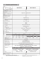
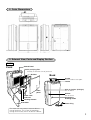
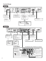
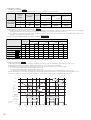
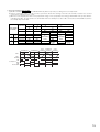
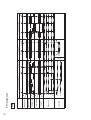
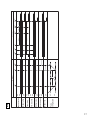
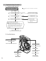
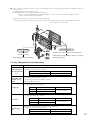
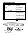
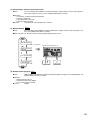
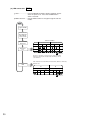
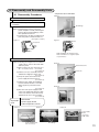
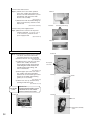
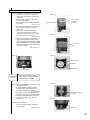
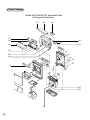
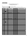
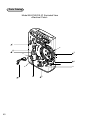
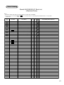
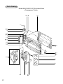
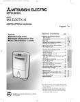
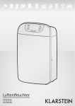
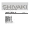
MITSUBISHI ELECTRIC
ADVANCED AND EVER ADVANCING
2003
DEHUMIDIFIER
SERVICE MANUAL
Model
No.MJW-21
MJ-E16S/E16SX-S1
Sold from 2003
CONTENTS
1.
2.
3.
4.
5.
6.
PRODUCT SPECIFICATIONS........................................................................................ 2
OUTER DIMENSIONS .................................................................................................... 3
EXTERNAL VIEW, PARTS AND DISPLAY SECTION................................................ 3 ~ 8
TECHNICAL POINTS.................................................................................................. 8 ~ 10
DAILY CHECKS AND MAINTENANCE ........................................................................ 11
WIRING DIAGRAM AND BLOCK DIAGRAM
6.1 Wiring Diagram....................................................................................................... 12
6.2 Function List ....................................................................................................... 13 ~ 15
6.3 Timing Charts ..................................................................................................... 16 ~ 20
6.4 Board Diagrams (Component Side) ....................................................................... 21
6.5 General Block Diagram ...................................................................................... 22 ~ 25
7. TROUBLESHOOTING PROCEDURE
7.1 Troubleshooting flowchart ..................................................................................... 26
7.2 One-Point Service .............................................................................................. 26 ~ 27
7.3 Key Component Check Procedures ....................................................................... 27
7.4 Error Indications and Corrective Actions ............................................................... 28
7.5 Self-Test Program and Execution Procedure .................................................... 28~ 30
8. DISASSEMBLY AND REASSEMBLY HINTS ........................................................... 31~ 34
9. CONTINUOUS WATER DRAINAGE ............................................................................. 35
PARTS CATALOG .......................................................................................................... 36~ 43
10. TROUBLESHOOTING................................................................................................ 44~ 45
PRECAUTIONS ............................................................................................................... 46~ 47
1. Product specifications
Model
MJ-E16S-S1
MJ-E16SX-S1
Dehumidifying capacity
16.0
Laundry
41
Continuous dehumidifying
37
single phase, 220-240V, 50Hz
Power supply (phases,V,Hz)
Power consumption (W)
275
Operating current (A)
1.3
Starting current (A)
5.5
Color tone
Metallic Blue (A)
Dimensions (H × W × D mm)
570 × 384 × 183
11.7
Weight (kg)
HFC - 134a, 120g
Coolant quantity (g)
Evaporator
Slit fin
Condenser
Slit fin
Thermal overcurrent relay
Model
XB460 VTE (rotary)
Output (W)
150
Winding resistance (Ω)
Primary: 26.1 , subsidiary: 70.7
With temperature fuse
Type
Sirocco fan
Output (W)
16
4
Flow rate selection
2.5
675-700
Low
720 [740]*
2.6 [2.7]*
2.4-2.5
675-700
2.4-2.5
Operating room
temperature (reference) (°C)
[2.7]
2.4-2.5
675-700
675-700
2.4-2.5
Built-in humidity sensor
Tank full protection
Reed switch (automatic)
Tank capacity (liters)
Auto-stopper tripped with about 4.0 liters of water
Continuous drainage
Commercial hose (inside diameter 15 mm)
Indications
Timer
2.6 [2.7]*
Hot gas type
Humidity control
Operation modes
2.4-2.5
720 [740]*
1 ~ 35 (°C)
Defrosting method
LOW · EASY DEHUMIDIFYING · LOW TEMP · AIR PURIFIER (E16S) · LAUNDRY ·
AUTO (E16SX) · MILDEW GUARD (E16SX)
E16S
Common
E16SX
LAUNDRY ·
AIR PURIFIER ·
OFF TIMER
(2 · 4 · 8h)
LOW · LOW TEMP ·
EASY DEHUMIDIFYING ·
TANK FULL · COLD ·
DEFROST
LAUNDRY · MILDEW GUARD · AUTO ·
CURRENT HUMIDIFY · SELECTION HUMIDIFY ·
ON/OFF TIMER(1-9h) · SWING LOUVRE(WIDE,
UPWARD, REAR) · CHILD LOCK
Off timer (2 · 4 · 8h)
On/Off timer (1-9h)
Air cleaning performance
Yes
Plug socket rating
16A
The operating noise levels indicated are
typical values measured in our anechoic room.
2
E16SX
[740]*
675-700
Laundry
Flow rate (m3/min)
700
Common
Laundry
Speed (rpm)
Air purifier
E16S
Easy Dehumidifying
Blower
Product performance
Blower protection
Auto
Compressor
Compressor protection
Mildew Guard
Operating noise
levels(dB)
(30°C room temperature, 80% relative humidity) (liters/day)
Low Temp
Electrical
characteristics
Performance
Item
* The brackets [ ] enclose values measured at a room
temperature of about 15°C or lower.
2. Outer Dimensions
3. External View, Parts and Display Section
E16SX
Front
Control Panel
Air purifying filter
Already installed at time of purchase
Air filter
Back
Handle
Raise handle to transport
Louvre
Front
panel
Water Tank
Tank Lid
Floating element
Front door
Side air intakes (left/right)
Do not block
Sensor
Do not cover
Continuous
drainage outlet
Power Plug
The water tank may contain water residue at
time of purchase. This is from final product
testing at the factory and is not due to a defect.
3
Control Panel
MJ-E16S
¡ COLD Lamp
¡ OFF Timer Lamp
Lights when the room
temperature drops
below 15°C
¡ Lamp
¡ Power button
Current mode lights
Set time lights
Use this to switch the
unit OFF and ON.
¡ Auto button
¡ OFF Timer button
For swiching mode the
EASY DEHUMIDIFYING
For setting the Timer
¡ Mode button
For switching from one
operating mode to
another
¡Tank full Lamp
This lights up to warn that the
water tank is full.
¡ DEF Lamp
Lights during
Defrosting mode
5 operating modes
Auto
¡ EASY
DEHUMIDIFYING
¡
¡
¡
¡
MODE
LOW
LAUNDRY
LOW TEMP
AIR PURIFIER
MJ-E16SX
¡Lamp
Current mode lights
¡Selection button
Switches modes
¡Mode button
For switching from one operating
mode to another.
¡Child lock
To set the child lock, press the
mode button for three seconds.
¡Swing louvre button
Sets swing louvre
direction or locks it
into position
¡Power lamp
Lights when unit is ON.
¡Power button
Use this to switch the
unit ON and OFF.
¡Humidity Selection
This is used to set the target
humidity.
6 operating modes
SELECTION
¡EASY
DEHUMIFYING
¡LAUNDRY
MODE
¡LOW
¡MILDEW GUARD
¡LOW TEMP
¡AUTO
LCD Panel
The LCD panel provides an explanation of all operations.
¡Information display
¡Mode Indicator
Indicates the current
operating mode.
¡Humidity Indicator
This indicates the
approximate humidity.
...indicates the
current humidity
...indicates the
humidity setting in
AUTO mode
The current humidity is displayed
in a range from 30 to 80%.
4
¡Tank full lamp
This lights up to warn that
the water tank is full.
¡Timer ON/OFF
Sets timer
Indicates room and unit
condition
...Flashes when the power is
OFF and the humidity rises
...Lights when the defrosting
function is operating.
...Lights when the power is
ON and the room
temperature drops below
15°C.
¡Swing monitor
Indicates the direction
of the swing louvre.
¡Timer display
Displays the time set
for the ON/OFF timer.
¡Child lock Indicator
Appears when the child
lock is on.
<Modes>
Humidity
level (%)
¡ Easy Dehumidifying
E16S E16SX
60
50
0
20
27 30
Room temperature (°C)
¡ Low
The unit automatically controls airflow to counter excessive
room temperature/humidity. It activates the blower at high
temperatures.
¡ Room temperature is below 27°C - the unit
automatically sets the humidity level
according to the temperature.
¡ Room temperature is above 27°C - the unit lowers
the humidity level to 50%, then activates the blower.
The dehumidifier is reactivated when humidity rises
to 60%.
¡ LAUNDRY
E16S E16SX
The unit continually operates the dehumidifier
regardless of current humidity.
¡ Low Temp
The unit operates continuously automatically
controlling airflow according to room
temperature. The air flow is strongest below
15°C. The use of Low Temp mode is
recommended when the Low temperature
indicator is lit.
~ 12 m2
E16S
Continuous dehumidifying regardless of
current humidity at high airflow.
¡ Air Purifier
E16S E16SX
Use standard
Effective
floor area
E16S
Cleans the air by passing it through the air
filter.
The dehumidifying function is off.
Air passes through the air filter when the
dehumidifying function is on.
When the temperature is low,
condensation may still form on
windows exposed to the outside air even when
Low Temp mode is operating
Information
Information
¡ Easy Laundry
E16SX
The unit operates for 12 hours and automatically switches off.
∞ Empty the water tank before operating the unit. The unit may stop before the clothes are dry due to a full tank.
∞ Do not use in conjunction with OFF Timer mode. The unit may stop before the clothes are dry.
∞ The following conditions prevent clothes from drying well:
Room temperature below 15°C, large volume of laundry; laundry not spaced well; clothes of thick fabric
and spacious room.
∞ When the room temperature is below 5°C, less water evaporates from the
Use standard
clothes, decreasing the amount of temperature change. Therefore the unit is
Effective
~ 10 m
floor area
unable to detect the state of the laundry and may turn off after 1 hour.
Laundry
Up
to
∞ Restart the unit if it turns off before the laundry dries (except when the temperature is
volume
approx. 4 kg.
below 5°C).
2
¡ Mildew Guard
E16SX
The unit lowers room humidity levels once a day (for approximately 2-4
hours), suppressing mildew growth.
Information
¡ Once every 24 hours the dehumidifier runs for 2
hours if the humidity is 40%, or 4 hours if at
50%. The unit operates intermittently,
automatically turning on and off according to
the humidity level of the room.
¡ The unit continues operation if the humidity level
does not decrease.
ON
24 hours
24 hours
Standby
Dehumidifies
Standby
Dehumidifies
∞ Refrain from turning on ventilation fans or opening windows or doors as this lowers performance.
∞ Mildew growth may still occur due to the fungus type and conditions of the room.
E.g. Rooms that contain excessive condensation, bathrooms, and places with bad airflow
Use standard
(insides of closets and behind furniture).
Effective
∞ This mode does not remove existing mildew.
floor area
~ 12 m2
∞ Do not use in conjunction with OFF Timer mode.
¡ Auto
E16SX
The unit maintains the humidity level by
automatically controlling airflow and operating
intermittently as necessary. All you have to do
is set the humidity level.
Information
¡ The unit turns off when current humidity
decreases past the set humidity level, and
restarts when the level is exceeded.
¡ The unit operates for 6 minutes continuously
regardless of the humidity level immediately after
turning the power on.
Frequent use of exits and room
size/conditions may cause the humidity to not
reach the set level.
<To view set humidity level/ To set humidity level>
¡ Pressing the button once displays the
set humidify level with the SELECTION
indicator. After 3 seconds, the display
returns to the current humidity display.
Press ¡ Pressing HUMIDITY SELECTION while
SELECTION is displayed sets the
humidity level. Each time the button is
pressed, the humidity setting changes.
70
65
60
55
50
5
<Indications>
E16SX
E16S
High humidity warning
Low indicator
Cold lamp
The
indicator flashes when the humidity in
the room exceeds 75%.
Activating the dehumidifier is recommended
when the
indicator is flashing.
When the room temperature falls below 15°C while the unit is operating, the lamp turns on or the
indicator appears.
If the High humidity warning is not used, remove the
power plug from the power socket. E16SX Only
E16SX
E16S
Tank full lamp
Defrosting lamp
The unit automatically shuts down and indicates with the lamp and sound
that the water tank is full. Empty the water tank.
The air flow (dehumidifier) is stopped when the lamp is lit. The frost
accumulated inside the unit is melted, and drained to the tank. After
defrosting is complete, the unit restarts.
¡ Defrosting lamp is lit
¡ Air flow is stopped
¡ Operating sound has changed
The unit automatically performs this function when the room temperature
falls below 15°C.
(During peak periods, the unit will perform this function once every 40 minutes
for 5 to 10 minutes.)
¡ Tank full lamp
lights
The unit beeps continuously.
¡ Air flows stops (louvre stops)
¡ Monitor turns off
• After removing the water and replacing the tank, the Tank full lamp will go
off, and the unit will automatically return to operation mode.
• When the Tank Full lights up, no operation but ON/OFF is possible.
<Viewing the Swing Monitor>
¡Stop swing
operation
¡ The louvre stops in a
vertical position.
¡ The swing monitor turns
off.
Defrosting indicator
This indicates the range of louvre swing.
(The louvre and monitor do not move in synchronization.)
¡REAR
¡WIDE
¡UPWARD
To cover the entire
room.
For drying clothes, etc.
To change the louvre
to a desired angle, wait
until the louvre stops,
then adjust by hand.
For directing air
into a closet.
Swings slowly to
send air further
Swing speed is
automatically controlled to
send air to all corners of the
room.
With each press
of the button
<Timer> E16S
To set
Press the Power button.
(Power off)
Switch the power on
Select operating mode
¡ The OFF Timer is
cancelled
Select desired operating mode
Set operating time
Blank
Press
¡ OFF Timer lamp indicates remaining time
¡ Power automatically turns off at set time
Press
<When you want to disable the Timer
OFF mode, and continue operation>
¡ One press - 2HR is
displayed
¡ Each consecutive
press displays the
following setting
(2 ➝ 4 ➝ 8)
➝ The OFF Timer is set
6
<When you want to turn the unit off>
Open the louvre manually
Hold down the button until
the OFF Timer lamp goes
out. The unit returns to Low
mode
Press
¡ The OFF Timer is cancelled
Information
1
2
3
4
To cancel
Empty the water tank before operating. The unit
stops and the Tank full lamp lights if the tank
becomes full during operation.
E16SX
<<ON timer operation>>
<<OFF timer operation>>
The ON timer can be set for 1 to 9 hours.
Set the timer when the power is switched off.
The OFF timer can be set for 1 to 9 hours.
Set the timer when the power is switched on.
To set
To set
1 Switch the power off.
2 Set the time you wish the unit to turn on.
1 Switch the power on.
2 Select operating mode.
Select desired operating mode.
Press
¡ Press once. The Power lamp, Mode indicator, and a [ ] on the
digital display flash. The [ON] indicator lights.
¡ Each subsequent press changes the display in order from 1 to 9
hours. (Hold the button to run automatically through the numbers.)
3 Change the louvre swing direction.
Select the desired setting.
4 Set the operating time.
Press
No Display
(operation
is off)
¡ When pressed once the figure [ ] and [OFF] appear.
¡ Each subsequent press changes the display in order from 1 to 9
hours. (Hold the button to run automatically through the numbers.)
3 Select operating mode.
Select desired operating mode.
No Display
(operation
is off)
4 Change the louvre swing direction.
Select the desired setting.
➝ The OFF timer is set.
5 Confirm the operating start time.
The following is an example of a display indicating AUTO
dehumidifying (set to 60%), swing set to WIDE and the OFF timer set
for 2 hours.
Press
¡ Power lamp and Time display light. ➝ The ON timer is set.
The unit informs you if you forget to press the Power button by making the
Time display and Mode indicator blink and sounding an alarm for 1 minute.
The following is an example of a display indicating AUTO dehumidifying
(set to 60%), swing set to WIDE and the ON timer set for 5 hours.
¡ The time remaining until the unit switches itself off is indicated in
increments of one hour with a flashing numeral.
¡ When the set time is reached, the unit switches itself off and the
louvre closes automatically.
To cancel
<When you want to turn the unit off>
Press the Power button. (Power off)
¡ The time remaining until the unit switches itself on is indicated in
increments of one hour with a flashing numeral.
¡ When the set time is reached, the unit switches itself on.
To cancel
Press
Press the Power button. (Power off)
¡ The OFF Timer is cancelled.
Press
<When you want to disable the Timer OFF mode, and
continue operation>
Keep pressed until the remaining time display disappears. The unit returns
to Low mode.
The ON timer function is not operable using a commercially-available
timer plug outlet.
Press
¡ The OFF Timer is cancelled.
Information
Information
¡ The timer is cancelled.
∞ The OFF timer and ON timer cannot be set at the same time.
∞ Do not use the timer OFF mode in conjunction with Laundry or Midew
guard.
∞ Empty the water tank before operating. The unit stops and the Tank
full lamp lights if the tank becomes full during operation.
7
<Using the Child Lock>
E16SX
To Lock
Releasing the child lock
Press for 3 or more seconds.
¡ The child lock indicator
The child lock is switched off when the power cord is unplugged.
Press for 3 or more seconds.
¡ The child lock lamp goes out.
When the child lock is activated the unit cannot be switched off or on. The
other switches are also inoperable until the child lock has been released.
¡ If you lock the unit when the POWER is OFF.
The unit will not turn on, even if you press the POWER switch to turn it on.
Only the CHILD LOCK lamp will blink. (Press the POWER button once
again so that the lamp lights.)
¡ If you lock the unit when the POWER switch is ON.
The unit will not turn off, even if you press the POWER switch to turn it off.
Only the CHILD LOCK lamp will blink. (Press the POWER button once
again so that the lamp lights.)
4. Technical Points
4.1 The technical points of the new products
E16S
1) Powerful 16-liter/day humidifying *1
Quick relief from the damp and uncomfortable sensation caused by humidity. Mold and fungus can grow when
failing to dehumidify closets, dressing rooms, shoe cabinets and other spaces where humidity is prone to collect,
causing damage to the home and clothing. A single high-capacity unit is effective in dehumidifying and drying
various locations throughout the home, quickly moving from one point to the next. Mobilizing the 16-liter/day
dehumidifying power, rooms can be dried out in about 40 minutes.*2 Besides this, laundry drying takes about 120
minutes.*3 This is a caliber of speedy dehumidification available only with the 16-liter type.
E16SX
1) Powerful 16-liter/day humidifying *1
Quick relief from the damp and uncomfortable sensation caused by humidity. Mold and fungus can grow when
failing to dehumidify closets, dressing rooms, shoe cabinets and other spaces where humidity is prone to collect,
causing damage to the home and clothing. A single high-capacity unit is effective in dehumidifying and drying
various locations throughout the home, quickly moving from one point to the next. Mobilizing the 16-liter/day
dehumidifying power, rooms can be dried out in about 40 minutes.*2 Besides this, laundry drying takes about 120
minutes.*3 This is a caliber of speedy dehumidification available only with the 16-liter type.
2) Keep your house fresh year-round with the highly rated “135° wide-angle louvre”
The ability to switch between the three settings of (1) REAR swing, (2) UPWARD swing and (3) WIDE swing makes it
possible to cope with different applications, for more effective dehumidifying than ever before.
(1)REAR swing ➝ Effective for closets, shoe cabinets and around the kitchen.
(2)UPWARD swing ➝ Effective for drying laundry, other uses. The swinging of the nozzle prevents uneven drying,
while speeding up the overall process. Laundry drying time is approx. 104 minutes.*3
(3)WIDE swing ➝ Effective for quickly dehumidifying spacious room areas with the 135° wide-angle swing.
*1 Dehumidifying volume when operating for 24 hours at room temperature 30°C and relative humidity 80%.
*2 Test conditions: Room size 13m2, room temperature 25°C, time needed to reduce relative humidity from 90% to 60%.
*3 Humidifier laundry drying performance displays values measured by the autonomous standards of the Japan Electrical
Manufacturer’s Association (JEMA-HD090) established in February 2001.
Test conditions: Room size 10m2, room temperature 25°C, relative humidity 70%, laundry weight approx. 2kg (including 2 dress
shirts, 1 pair of pajamas, 3 T-shirts, 7 pairs of underwear, 3 face towels, 2 pairs of socks). Drying time will vary by the type of
building, other conditions.
8
4.2 Operation and Performance
Working temperature
Defrosting
Dehumidification is possible with a room temperature of 1
– 35°C. If the room temperature exceeds 35°C, however,
the temperature inside the unit will increase; therefore,
the protective device may activate and halt operation in
some cases. For this reason, the louvres should be aimed
upward.
• If the room temperature is lower than 1˚C, there is
danger of the removed water freezing, making
dehumidification impossible, so the fan will start
operating.
The unit may display
during operation and stop air
flow, followed by a change in the operating noise. The
unit has stopped the airflow, and is melting internal frost
into the water tank. The unit will resume automatically
when the defrost operation completes.
Wait for 3 minutes before dehumidifying
Heating during operation
The dehumidifier will not operate for 3 minutes when the
unit is turned on immediately after being turned off or
plugged in. (In order to protect the compressor.)
When dehumidifying begins, the operational noise
increases. This is not a malfunction.
This dehumidifier has no cooler function. In fact it emits
some heat causing the room temperature to rise by 2 to
4°C. The unit may produce warm air, but this is not due to
a malfunction.
This operation will be performed automatically when
the room temperature is approximately 15°C or
lower. (When humidity is high, this will occur
approximately once every 40 minutes for 5 – 10
minutes.
Room size guide
The size of a room that can be dehumidified differs depending on the house structure and room style, etc.
Room size guide
Model
MJ-E16S/E16SX-S1
Single wooden dwelling
Japanese style room
~ 33m2
Single prefab dwelling
Western style room
~ 51m2
Group housing (concrete, lightweight concrete)
Western style room
~ 67m2
Current Level of Humidity
The current humidity indicated by the dehumidifier may sometimes
differ from the humidity indicated by an ordinary hygrometer but this is
not a malfunction.
1. If the air temperature at the location where the dehumidifier is
installed and the place where the hygrometer is located differ, the
relative humidity will also differ.
2. The flow of air (ventilation) also affects the humidity, which may
differ for objects around the periphery and depending on the
installation location, etc.
What is relative humidity?
Relative humidity is the mass of
water vapor present in the air
expressed as a percentage of
the mass that would be present
in an equal volume of saturated
air (100%) at the same
temperature. The dehumidifier
and an ordinary hygrometer
indicate this relative humidity.
How does the dehumidifier work?
If you pour cold water into a cup, the air around it becomes cold, causing water
droplets to form on the surface of the cup. The dehumidifier takes advantage of this
phenomenon to remove moisture from the air.
Dried (warm) air
e
Cooling coil
Moist air
q
Compressor
w
1 The unit draws air from the room,
cools it with its cooling coil, causing
the moisture to transform into water
Re-heating
droplets.
coil
2 The water droplets fall into the water
tank.
3 The dehumidified air is reheated by
Water tank
the heating coil, and then discharged.
The humidity of the room is thus reduced
by repeating steps 1, 2, and 3.
9
4.3 Coolant Circuit
φ5
Compressor
Coolant flow
Dehumidifying
Defrosting
φ5
φ5
φ6.35
Tube temperature
sensing thermistor
Solenoid
valve
Heat exchanger
(heat radiation)
Blow
Fan
(closed when
dehumidifying
and open when
defrosting)
Capillary tube
Humidity
sensor
φ5.0 × φ4.0
Heat exchanger
(cooling)
φ6.35
Intake
Room
temperature
sensing thermistor
φ6.35
φ6.35
Capillary tube
φ2.0 × φ0.8 × 340
4.4 Performance curve
Relationship between dehumidification and room temperature/humidity
Dehumidification capacity (L/day)
The lower the temperature and humidity, the smaller the quantity of dehumidifying as shown on the graph.
in case of
80% humidity
16
14
12
in case of
60% humidity
10
8
6
4
2
0
5
10
15
20
25
30
Room temperature (°C)
LOW TEM Mode (
High Mode ( )
)
• Operation in low temperatures
Operating the LOW TEMPERATURE mode produces greater dehumidification than when on HIGH for
days when the temperature is low, but humidity is high due to snow or rain.
• The dehumidification quantities shown on the graph were measured at constant temperature and humidity, and do
not reflect actual usage conditions.
• In winter, the air is so dry that dehumidification is almost impossible.
10
11
2
1
Front
panel
Air filter
The air purifying filter cannot be washed
in water.
Replace the air purifying filter when it
becomes dirty.
Air purifying filter
Remove the air-purifying filter
Run a vacuum cleaner
lightly over the air filter
surface to remove the
dirt.
2 Hook the top edge to
the top part of the unit
and push the bottom in.
Attach the air filter and front panel
Honeycomb
side
Set the air-purifying filter into the air
filter with the honeycomb side up.
Set the air-purifying filter
Hose with lukewarm water when
excessively soiled. Dry well.
Clean air filter
1 Attach holding the
tabs.
5
4
3
Debris clogging the air filter reduces the effectiveness of the dehumidifier.
Clean once every 2 weeks.
2 Remove
1 Remove holding
holding the
the bottom
tabs
If the metal fin inside the main unit is slightly
bent, the unit’s performance is not affected.
Air filter
Wipe with a
soft cloth.
Main unit
Once every two weeks
The unit draws in dust present
in the air, and this may cause
the tank to gradually become
dirty. If the dirt does not come
off easily, wash with cold or
warm water, then wipe with a
soft, dry cloth.
Remove front panel and air filter
Air filter
Floating
element
Do not remove
or dismantle.
Wipe with a soft cloth.
Water tank
Confirm that the lid is
securely attached to the
water tank, and push the
tank in. Close the front
door.
Reattach the tank lid and replace
the water tank.
Pour the
water out as
shown.
3
water tank
1
2
Float
Do not remove
Do not remove or dismantle the floating element
in the tank. If it is removed, the unit cannot detect
when the tank is full, and this could result in
leakage.
Replace the filter when it becomes dirty
(brownish) with cigarette smoke, dust, etc.
Generally, one filter should last about 6 months.
(This will depend on usage conditions.)
When to replace it
∞Type: MJPR-SXFT
∞Type code: 5C5 813
For these items contact your nearest Mitsubishi
Electric dealer.
Air purifying filter for replacement
Parts sold separately
Attach air filter and front panel
Replace air-purifying filter
Remove front panel and air filter
For maintenance procedures see p10.
Replacing air purifying filter
Remove the tank lid, and empty.
¡ If the lid is not properly closed, you may have
problems removing the tank.
¡ If the tank is not installed correctly, the tank
full light will come on, and the unit will not
operate.
3
2
<Hold the tank this way.>
Grasp handle and slide out
Remove the water tank.
Open the front door
1
The air purifying filter is disposable.
The air purifying filter is disposable.
Make sure to replace the filter when it becomes dirty.
(The filter cannot be washed or reused.)
The unit automatically shuts down and lights the Tank
full lamp when the tank (approximately 4L) is full.
Empty the tank.
Do not use detergents, cleaning agents for heat exchange equipment, abrasive powders, chemically treated
dusters, gasoline, benzene, thinners or other solvents, as they can damage the unit or the water tank, which may
result in leakage.
Cleaning
Replacing the Air Purifying Filter
Removing Water from the Tank
Maintenance
5. Daily checks and maintenance
Note
6. Wiring Diagram and Block Diagram
6.1 Wiring Diagram
CM
R
FM
SV
Solenoid valve
Overload relay
C
Fan motor
Compressor
E16S
S
Gray
Run capacitor
P5
P2
P10
1°C (defrost)/12°C (end)
P4
Gray
P11
Blue
Power supply board
P1
Power plug
White
P100
White
P3
Brown
Blue
Blue
Yellow
Black
Blue
White
Red
Gray
P200
Brown
Sensors
(Humidity and room
temperature sensing)
Control board
Thermistor (Tube
temperature sensing)
White
White
Brown
Gray
Tank full switch
P13
Gray
CM
R
FM
SV
Solenoid valve
Overload relay
C
Fan motor
Compressor
E16SX
S
P200
Sensors
(Humidity and room
temperature sensing)
P201
Brown
Brown
White
White
Blue
Blue
Yellow
Black
Blue
White
Red
Gray
Control board
P5
P2
P3
P100
Gray
Run capacitor
P101
P10
P4
1°C (defrost)/12°C (end)
Gray
Blue
Power plug
Brown
P1
Power supply board
P11
SM
P20
P13
Thermistor (Tube
temperature sensing)
White
White
Gray
Stepping motor
Tank full switch
Gray
Safety Devices
(1) Current fuse ....................Overcurrent flow caused by deterioration in electrical parts or other problems
turns the power source to OFF.
<Current setting: 2A>
(2) Motor protector................Current flow exceeding 1.7A with compressor surface temperature of approx.
(Overload relay)..............100°C shuts down compressor operation.
The compressor will also shut down when malfunctions or other problems
cause the current flow to exceed 4.7A.
(3) Control circuitry ...............The room temperature thermister senses temperature below about 0°C, and
shuts down the compressor.
12
(4) Thermal fuse ...................When blower motor temperature exceeds 134°C due to blower locking or other
malfunctions, blower operation shuts down.
6.2 Function List
E16S
Laundry
Low temp
Air purifier
ON
ON
ON
OFF
ON
ON
ON
ON
ON
OFF OFF OFF
OFF
Blower
OFF
Solenoid value
OFF OFF OFF
OFF OFF OFF
Defrost
Off timer
Low
ON/
OFF
ON/
OFF
Compressor
Tank full
Easy
Dehumidifying
Operation off
Operation mode
Dehumidifying operation
OFF OFF
OFF OFF
ON
One item is
Easy dehumidifying
Low
Indicator
Laundry
Low temp
Air purifier
Off timer
Tank full
Defrost
Low temperture
※
= Lit.
= Can light.
= Not lit.
Switch
Note
: Display lamp/Operable
: Timer – flashes when on
: Off/stopped/inoperable
: Operable only when swing on/lit
: Operable only when swing on and blower fan rotates
Child lock
On timer
counting
ON
OFF
ON
OFF
On timer
being set
Low
Temp
OFF
OFF
OFF
OFF
Off timer on
Mildew
guard
OFF
Defrost
AUTO
OFF
Tank full
OFF
Laundry
OFF
ON
ON
OFF
Easy
dehumidifying
Low Temp
Compressor
OFF
Blower
OFF
Solenoid valve
OFF
OFF
Swing louvre
Closed
Power
Easy selection mode
Tank full
Humidity (set/current)
Operation mode
LOW
Swing
On/off timer
Mildew/guard
Defrost
Low temp
Child lock
Operation
Auto
Operation switch
Selection
Swing louvre
On/off timer
Child lock
Auto
LOW
Operation mode
Dehumidifying operation
Mildew
guard
LCD indicator
LED indicator
Operation off
E16SX
OFF
OFF
OFF
OFF
OFF
OFF
Closed Closed
Off
On
On
: Only lit (only displays swing range)
: LCD lights at each operation mode
: LCD flashes at each operation mode
: Lights at room temperatures of 14°C or under
: Varies by conditions.
13
<Operation Control>
1 Humidity set operation
E16SX
(a) Compressor and blower fan operation will switch by current humidity and set temperature.
Blower fan rank
Decline in
current
humidity
Rise in current Compressor
humidity
36°C
29°C
27°C
Current humidity
– Set humidity
34°C
+5%
ON
Rank 1
Rank 2
Rank 5
+1%
ON
Rank 1
Rank 2
Rank 5
OFF
Stopped
Stopped
Stopped
+3%
–1%
2 Specifications shared at all operation modes
E16SX
(a) Dehumidifying will not start for about 2 seconds when turning the operation power on with the swing stopped. (However, humidifying
will begin immediately when pressing the swing louvre switch within 2 seconds of turning the power on.)
(b) The compressor and blower fan will operate for about 7 minutes after turning on the operation switch or activating the compressor,
regardless of humidity or temperature levels.
3 Low, Low Temp, Mildew Guard, Air Purifier, Laundry
E16S
E16SX
Blower fan rank
Compressor
16°C
29°C
27°C
14°C
E16SX
36°C
34°C
E16S
E16SX
E16S
E16SX
E16S
E16SX
E16S
E16SX
Low
ON
ON
Rank 1
Rank 1
Rank 1
Rank 1 Rank 2
E16S
Rank 2
Rank 5
Rank 5
Low Temp
ON
ON
Rank 6
Rank 6
Rank 1
Rank 1 Rank 2
Rank 2
Rank 5
Rank 5
Mildew Guard E16SX only
–
ON
–
Rank 1
–
Rank 1
–
Rank 2
–
Rank 5
Air Purifier
E16S only
OFF
–
Rank 2
–
Rank 2
–
Rank 2
–
Rank 2
–
Laundry
E16S only
ON
–
Rank 3
–
Rank 4
–
Rank 4
–
Rank 5
–
Laundry
E16SX only
–
ON
–
Rank 3
–
Rank 4
–
Rank 4
–
Rank 5
* Rank 1=Lb, Rank 2=La, Rank 3=Mi, Rank 4=Hi, Rank 5=HH, Rank 6=SH
4 Mildew Guard mode
E16SX
(a) Alternately activates/deactivates compressor or blower according to current humidity/time. (Fan rank is as shown in 2)
(b) Operates dehumidifier when Mildew guard mode is activated or every 24 hours after activation.
(c) Dehumidifier is deactivated when the following parameters are breached. (Compressor and blower stop)
• 2 hours of below 40% elapses and below 35% is detected.
• 4 hours of below 50% elapses and below 45% is detected.
* However, if the humidity rises above the given levels for more than 3 minutes, the accumulated time returns to zero.
(d) If the humidity rises to 75% after deactivation, the dehumidifier automatically operates until the humidity is brought down to 65%.
(e) If 24 hours elapse from the time the unit was turned on, all accumulated time counts for all humidity levels are reset.
75%
Limit
75%
65%
Limit
recovered 65%
Humidity level
Below
45%
45%
40%
3 minutes
above 40%
elapse
35%
Below
35%
24HR
45%
Elapsed time
4HR
35%
Elapsed time
Compressor
Blower
4HR
2HR
2HR
ON
OFF
Mildew
Guard
ON
14
Below 45%
time count
start
Below 35%
time count
start
Below 35% Dehumidifier
time count deactivated
stop
Accumulated
time counts
reset
Below 35%
time count
start
Dehumidifier Dehumidifier
deactivated activated
Dehumidifier
deactivated
5 Easy Dehumidifier
E16S
E16SX
(a) Modifies humidity setting or operates CIRCULATE mode (blower only mode) according to the room temperature.
(b) Switches temperature table every 60 seconds to prevent the blower from turning on and off at the 3-minute restart for the coloured
section in the chart below. (51% – 59%)
(c) When the room temperature is above 29°C (temperature rising) or 27°C (temperature decreasing), CIRCULATE mode operates with the
humidity below 50%. The unit activates the dehumidifier when the humidity rises above 60%, and returns to CIRCULATE mode when
the humidity drops below 50%.
22°C
Temperature
Current humidity
– Set humidity Temperature table
Set humidity
+3%
–1%
Fan rank
+5% Compressor
Fan rank
+1% Compressor
Fan rank
Compressor
29°C
20°C
0
34°C
1
60%
50%
Rank 1
ON
Rank 1
ON
Stop
OFF
Rank 1
ON
Rank 1
ON
Stop
OFF
Set humidity 60%
36°C
27°C
2
3
60%
Circulate
50%
Dehumidifier mode
60%
Circulate
To
Dehumidifier
mode
Rank 2
ON
Rank 2
ON
To
Dehumidifier
mode
Rank 4
OFF
To
Circulate
mode
Rank 5
OFF
50%
Dehumidifier mode
Rank 5
ON
Rank 5
ON
To
Circulate
mode
Circulate Dehumidifier mode
Circulate
Set humidity 50% set humidity 60% set humidity 50% set humidity 60%
60%
50%
Humidity
ON
OFF
Blower ON
OFF
Temperature ~20°C~
~27°C~
Compressor
15
16
Humidify
Blower fan
Float switch
Tank full light
Compressor
Operation mode
Operation switch
E16S
50%
60%
OFF
LO
Mi
Hi
SH
OFF
ON
OFF
ON
OFF
ON
OFF
ON
max
3 min.
min
7 min.
Easy
dehumidifying
Easy dehumidifying/ Mode
Mi for 2 sec.
at start-up.
Power
ON
6.3 Timing Charts
Mode button
ON
Auto
Easy
ON
3
sec.
Easy
dehumidifying
※ When room temperature is
between 20℃ and 27℃.
Room
temperature
Low temp
16℃
14℃
Low temp
Decrease in room
temperature
Increase in room
temperature
Auto
3
sec.
Drain
Tank full/ Power OFF
Tank full
Auto
Power
OFF
17
Tube
temperature
Blower fan
Solenoid valve
Compressor
Timer button
Timer lamp
Mode lamp
Operation switch
E16S
0℃
12℃
OFF
ON
OFF
ON
OFF
ON
OFF
ON
OFF
ON
OFF
ON
OFF
ON
Defrost count
start
40
min.
Defrost
Defrost
start
Defrost
finish
Off timer
ON
2hr
Off timer
ON
4hr
Off timer
ON
8hr
4 hr.
After 4 hr.
Off timer
4hr
2 hr.
After 1 hr.
2hr
2 hr.
After 2 hr.
18
Swing
on
Audible alarm
Louvre indicator
(“swing on” only)
Louvre
Swing
off
Low temperature
High Humidity
Warning
Tube temperature
Humidity
Tank full light
Float switch
Solenoid valve
Blower fan
Compressor
Mode display
Operation switch
E16SX
OFF
OFF
ON
OFF
ON
OFF
ON
OFF
ON
OFF
ON
ON
0°C
12°C
61%
60%
59%
OFF
OFF
ON
OFF
ON
OFF
ON
OFF
ON
OFF
ON
OFF
ON
ON
Closed
Operation
ON
Stopped
at 90°
Max 3 min.
Min 7 min.
AUTO (60%)
Dehumidifying Dehumidifying
stop
start
LOW
Humidity
set
LOW
TEMP
Operation
switch
MILDEW
GUARD
Operation
switch
Lights only with a room temperature of 14°C or less
Operation
switch
Wait 3 seconds
AUTO (60%)
Operation start/Mode switch/Operation stop
Wait 3 seconds
Operation
OFF
LAUNDRY
Selection
switch
EASY
DEHUMIDIFYING
Selection
switch
Closed
Closed
19
Swing
on
Audible alarm
Louvre indicator
(“swing on” only)
Louvre
Swing
off
Low temperature
High Humidity
Warning
Tube temperature
Humidity
Tank full light
Float switch
Solenoid valve
Blower fan
Compressor
Mode display
Operation switch
E16SX
OFF
OFF
ON
OFF
ON
OFF
ON
OFF
ON
OFF
ON
ON
0°C
12°C
75%
OFF
OFF
ON
OFF
ON
OFF
ON
OFF
ON
OFF
ON
OFF
ON
ON
40 min. elapsed
Defrost operation
start
Weak alert
tone
Defrost
Tank full
operation stop detection
Lights only with a room temperature of 14°C or less
Defrost count
start
Wait 3
seconds
Swing mode
switch
Swing mode display change
Swing mode change
Lights only with a room temperature
of 14°C or less
Tank empty
detection
Defrost operation/Tank full detection/Swing mode change/Mildew & mite display
Closed
Closed
Operation Humidity
OFF
rise
Lit
Humidity
decline
20
Swing
on
Audible alarm
Louvre indicator
(“swing on” only)
Louvre
Swing
off
Low temperature
High Humidity
Warning
Tube temperature
Humidity
Tank full light
Float switch
Solenoid valve
Blower fan
Compressor
Mode display
Operation switch
E16SX
OFF
OFF
ON
OFF
ON
OFF
ON
OFF
ON
OFF
ON
ON
0°C
12°C
75%
OFF
OFF
ON
OFF
ON
OFF
ON
OFF
ON
OFF
ON
OFF
ON
ON
On timer
ON
1 hour
elapsed
Area indication only
On timer Operation ON
ON
(Set to 2 hours)
2 hour
elapsed
Off timer
ON
1 hour
elapsed
Stopped at 90°
Swing mode display
Lights only with a room temperature of 14°C or less
Off timer
ON
On/off timer operation
2 hour
elapsed
Closed
Closed
6.4 Board Diagrams (Componet Side)
[Power supply board diagram]
[Control board]
E16S
E16SX
21
6.5 General Block Diagram
E16S
22
23
E16SX
24
25
7. Troubleshooting Procedure
7.1 Troubleshooting flowchart
The compressor does not operate in Air purifier
mode.
The unit does not operate
Start
Check AC power supply
Abnormal
Restore AC power supply
Normal
Blown
Has the fuse blown out?
Replace fuse
Not blown
Is the float switch turned on?
OFF
ON
Control board connector check
Mechanical check
• Correct defects.
• Replace the switch if
defective.
With the power plug removed from the
receptacle, remove and insert each connector
two to three times to improve its contact. Then,
insert the power plug into the receptacle to
make an operation check. Make sure that the
flat cable and the connectors are inserted
straight.
Uncorrected
Replace control board
7.2 One-Point Service
Compressor does not start
Compressor failure
Action: Replace the compressor
Unit does not run
Float switch operation check
Power button
operation check
Control board leadwire
connection check
Fan does not start
Control board failure
Fan motor failure
Action: Replace
the fan motor
26
Action: Replace
the control board
If the customer complains that the unit won’t dehumidify, make the following checks before starting to repair the
coolant circuit:
1 Clogged filter, or dust: ➞ Action: Clean.
2 Low-temperature, low-humidity operating environment:
➞ Action: See the explanation of the graph on page 9, or move the unit to a kitchen or bathroom and
request verification of its performance.
★ If the problem persists, check the cooler tube temperature.
Normal: At least 10°C lower than the room temperature ➞ If not lower than the room temperature by 10°C or
more, repair the coolant circuit.
No humidifying
Noise increase
Gas leak from the cooler, condenser or discharge pipe.
Pipe/pipe contact
Pipe/cabinet contact
Troubleshooting: Replace cooler or condenser; or replace
discharge pipe welding.
Troubleshooting: Repair pipe molding
7.3 Key Component Check Procedures
Component name
Tub temperature
sensing thermistor
P11
Room
temperature and
humidity sensor
board
Testing procedure
Detach the connector and measure the resistance using a multimeter
(component temperature: 10°C to 30°C).
Normal
Abnormal
Between P11 pins: 8.0kΩ to 20.8kΩ
Open or shorted
Detach the connector and measure the resistance using a multimeter
(component temperature: 10°C to 30°C).
Normal: 47 to 51kΩ (between P10 pins 3 and 4)
Abnormal: Open or shorted
With the connector detached, measure the resistance across the terminals using a multimeter
(winding temperature: 10°C to 30°C).
Abnormal
Normal
Compressor
C-R side
25.0Ω ~ 27.1Ω
C-S side
67.9Ω ~ 73.5Ω
Open or shorted
Measure the resistance between terminals using a multimeter
(winding temperature: 10°C to 30°C).
Solenoid valve
coil
Abnormal
Normal
Fan motor
Yellow-Blue
258Ω ~ 280Ω
Black-Blue
379Ω ~ 411Ω
Open or shorted
Measure the resistance between terminals using a multimeter
(component temperature: 10°C to 30°C).
Normal
Abnormal
2.6kΩ ~ 2.9kΩ
Open or shorted
27
7.4 Error Indications and Corrective Actions
Indication
(Timer display)
Error (failure)
Corrective action
Frequency determination error
All Mode
lamps lit
Check power plug and 100V power supply
(Try replacing main and power supply boards)
Replace main board
(Try replacing main and power supply boards)
Replace main board
E16S
Watchdog error
RAM error
Compressor
All timer
lamps lit
E16SX
E0
Check blowing performance
Check tube temperature thermistor
Check compressor operating noise
P10 connector out of position
Room temperature thermistor blowout
E1
Room temperature thermistor short
Room temperature and humidity
sensor board failure
E7
P11 connector out of position
Tube temperature thermistor blowout
Check the P10 connection.
Check the room temperature and humidity
sensor board.
Check the P11 connection.
Check the tube temperature thermistor.
E8
Tube temperature thermistor short
Tube temperature sensor failure
A1
Microprocessor failure
RAM error
A2
Frequency determination error
Check the receptacle and the 100 V
power supply (replace the main and power
supply boards).
A6
Watchdog timer error
Replace the main board (replace the main and
power supply boards).
P4
Compressor
Check blowing performance.
Check the tube temperature thermistor.
Check the compressor operating noise.
Replace the main board.
7.5 Self-Test Program and Execution Procedure
E16SX
(1) LCD and fan tests
●Start:
Simultaneously press operation MODE and HUMIDITY SET switches four times with the power
off. Press the operation switch within 2 seconds.
●Mode selection: Use the timer switch to change the diagnosis mode.
0
All
LCD and LED lit
※
1Microprocessor
2※Fan manual
version E2ROM
model display
operation
3
LED
segments lit
4
Model
code indication
All LCD and LED
return to lit status
Flow rate indication
(3 hexadecimal digits)
Flow rate: Hexadecimal × 16 µS
Examples
E2PROM model
information
Higher flow .......HUMIDITY SET switch
Lower flow .......Operation MODE switch
E2PROM version
“FF” displayed for E2PROM error
28
Microprocessor
version
(2) Deactivating 3-minute restart prevent lock
●Start:
Press the MODE and HUMIDITY SELECTION buttons (Auto buttons for the E16S) together 3
times when the power is off. Press the POWER button within 2 seconds.
●Functions:
1 Deactivates 3-minute restart prevention lock
2 Activates compressor
3 Operating mode: Low Temp
4 Operates blower on HIGH
●To end:
Turn power off. Valve functions for 3 seconds.
(3) Monitor display
E16SX
●Start:
Press the MODE and HUMIDITY SELECTION buttons together 5 times when the power is off.
Press the POWER button within 2 seconds.
●Mode selection: Use the time switch to change through display modes (0 to 3).
0
Humidity indication
30% ~ 80% 1% increments
1Room temperature
Example: Room temperature 21°C
indication
0°C ~ 39°C
2
Fan rank indication
0~6
3Tube temperature
data indication
0°C ~ 12°C
(4) Demonstration program
●Start:
21°C
Display mode
E16SX
Hold the MODE and HUMIDITY SELECTION buttons together and press the POWER button. The
demonstration starts after 3 seconds.
●Functions:
1 Blower locked at rank 3.
2 Compressor and valve stopped.
3 LCD and LED light at random.
●To end:
Unplug
29
(5) LED sensor test
E16S
Start...................... Press the MODE and AUTO buttons together 4 times
when the power is off. Press the POWER button
within 2 seconds.
Mode selection ..... Use the AUTO button to change through the self test
modes.
Lights all LEDs
Indicates Board
type switch data
and/or Micropr
ocessor version
Self test indication
Indicates EPROM2
data/version
Tube temperature thermistor
Indication
2hr
4hr
8hr
Tube temperature thermistor
Low temp Laundry
Low
Normal
Thermistor
test
Disconnection
Short circuit
indicates lit
Check the connection of connectors P11 (Tube temperature
thermistor) and P10 (Room temperature thermistor). Check
each thermistor.
LED
LEDs indicated detected humidity in hexadecimal. (Max: 83%. Min:50%)
Example: 83%
8
3
LED indication
2hr
4hr
8hr
LED indication
Easy
Air purifier Low temp Laundry
dehumidifying
Low
indicates lit
30
8. Disassembly and Reassembly Hints
8.1 Disassembly Procedures
* The pictures show an E16SX
Picture 1
1. Remove the water tank
(See Picture 1.)
2. Remove the front panel and air filter
assembly
Click fittings
Steps 1) Hold down the bottom of the front
panel and pull it forward (releasing the
bottom side click clamp fittings). Then
lift it upward and remove.
2) Hold down the air filter assembly knob
part, then pull it forward and remove.
Water tank
(See Figures 1 and 2)
Figures 1
Figures 2
Air filter
Front panel
Slight bending of the metal fan in the
main unit will have no negative impact
on performance.
3. Remove the front case assembly
Steps 1) Following the sequence in Procedures
1 and 2 above, remove the water tank
and front panel
2) Remove the front case setscrews (4 x
16 --- 2 screws, 4 x 12 --- 4 screws)
Picture 2
Special Setscrews
(See Picture 2)
Setscrews
3) Pull the front case assembly forward,
and detach it slightly from the unit.
(See Picture 3)
4) Lift up the panel, and remove the
power supply board setscrew (1).
(See Picture 4)
5) Pull the power supply board slightly
forward, release the box cover click
fittings (2 places) and remove the
cover.
Picture 3
(See Picture 5)
6) Disconnect the power supply board
connectors P100 and P101 (the cable
connectors linked to the main board),
and detach the front case assembly.
(See Picture 6)
Repairable
parts
Picture 4
Main board
Power supply board
Tube temperature sensor
Picture 5
Picture 6
Power supply
board
connectors
P100, P101
Power supply board
box setscrew (1)
Click fittings
31
<<Remove the main board >>
Steps 1) Pull the front case switch operation
part to the outside, detach the main
board cover side switch button (convex
part) fittings, and remove the main
board cover assembly.
Picture 7
(See Picture 7)
2) Release the main board click fittings (4
points on the bottom), and remove the
main board.
(See Pictures 8 and 9)
Picture 8
Fastening click fittings
<<Remove the power supply board>>
Steps 1) Detach the connectors in the power
supply board (P10, 11, 12, 13, 2, 3, 5,
1---8 connectors), and remove the
power supply board.
(See Picture 6)
Picture 9
4. Remove the rear case
Steps 1) Following the sequence in Procedures
1-3 above, remove the water tank,
front panel and front case assembly.
2) Remove the rear case setscrews (6).
Picture 10
(See Picture 10)
3) Hold the bottom of the rear case and
pull it to the outside, release the
bottom fitting and then push upward
while lifting the handle. Release the
handle slip prevention fitting, and
remove the handle.
Rear panel
setscrews
(See Picture 11)
4) Pull the upper part of the rear case to
the outside, and release the fitting
between the screw fastening boss and
blower fan assembly side fastening
guide (one on each side).
Picture 11
Handle
(See Picture 12)
5) Lift the rear case up, and remove by
passing it under the louvre.
(See Picture 13, 14)
Repairable
parts
Blower fan
Temperature/humidity sensor,
solenoid valve, float switch,
thermal overcurrent cutoff
Picture 12
Picture 13
Louvre
Fittings
(one on each side)
32
Temperature/humidity
sensor
5. Remove the blower fan assembly
Steps 1) Following the sequence in Procedures
1-4 above, remove the water tank,
front panel, front case assembly and
rear panel.
2) Remove the connectors (8) in the
power supply board.
3) Remove the power supply board box
assembly.
Picture 14
Solenoid valve
Power supply
board box
assembly
(See Picture 15)
4) Disconnect the blower fan guide case
lead wires on both sides from the
guide case.
5) Pull off the humidity/temperature
sensor side cushion tape from the
drain pan, and disconnect the sensor
lead wires from the guide case.
Picture 15
(See Picture 15)
6) Release the blower fan assembly and
drain pan click fittings on both sides,
(pulling upward while tipping the upper
part of the blower fan assembly toward
the heat exchanger side), and remove
the fan assembly.
Sensor lead
wire
(See Picture 16, 17)
Picture 17
Picture 16
Fan assembly
Blower fan
Blower fan nut
Click set fittings
Repairable
parts
Blower fan, blower motor,
float switch, heat exchanger
(radiant heat, cooling)
Steps 1) Remove the blower fan check nuts and
the blower fan itself.
2) Pull off the blower motor lead wire
fastening tape, and disconnect the
lead wires from the fan guide case.
Picture 18
(See Picture 18)
3) Detach the motor fastening plate and
cushion, and remove the blower motor.
4) Disconnect the blower fan guide case
lead wires on both sides from the
guide case.
Motor fastening plate,
setscrews
Picture 19
<<Float switch removal>>
Remove the float switch attached to
the drain pan.
(See Picture 19)
Float switch
33
6. Removing the drain pan assembly
Steps 1) Following the sequence in Procedures
1-3 above, remove the water tank,
front panel, front case assembly, rear
panel and blower fan assembly.
2) Release the drain pan and base
fittings, lift up the right side of the heat
exchanger while removing the base.
Picture 20
(See Picture 20 and 21)
Drain pan and base fittings
Repairable
parts
Compressor
Picture 21
Base
<Compressor wiring diagram>
Heat
exchanger
Red (S)
Gray (R)
White
Gray
White(C)
34
9. Continuous Water Drainage
If a drain is available, the unit can continuously drain excess water by attaching a commercially available hose
(internal diameter 15mm).
The unit can be operated for extensive periods without the need to empty the water tank.
Do not drain water continuously
if there is a possibility that
temperatures around the hose could
drop below freezing point.
CAUTION
Foreign objects, etc. could clog the hose
resulting in overheating and/or leakage.
Water inside the hose may freeze and water may leak
from the unit and damage surrounding objects.
1
Open the front door.
2
4
Remove the water tank.
When draining water continuously or
left unattended for long periods,
inspect the unit once a fortnight.
Insert the hose into the drainage
outlet on the back
Feed the
commercially
available hose (ID
15 mm) into the
drainage outlet
while keeping the
stopper pressed.
Grasp handle and
pull out.
Open the drainage outlet.
Confirm that the hose is
securely attached and
does not leak.
Hose
Use cutters to cut the three fixing ribs of the
continuous drainage port on the back of the main
unit, then remove it carefully making sure that it
does not fall inside the unit.
3
Press drain stopper.
Drain
Stopper
Note
Push here
∞ Leave a minimum space of 20 cm behind the
unit for attaching the hose.
∞ Confirm that the hose does not show signs of
deterioration such as cracks and clogging.
∞ Inspect the hose every 2 weeks.
Insects or dirt blocking the hose may cause
leakage resulting in malfunctions.
5
Replace the tank.
The unit cannot operate without returning the
tank.
How to set up the drainage hose
¡ hose immersed
in water
¡ hose raised to a
level higher than
the drainage
outlet
35
Parts Catalog
Model MJ-E16S/SX-S1 Exploded View
<Casing and Structure>
MJ-E16S
20
9
21
7
23
6
22
15
10
c
7
b
8
14
6
5
18
19
13
12
11
a
17
2
36
3
1
4
16
Parts Catalog
Model MJ-E16S/SX-S1 Parts List
<Casing and Structure>
Notes:
1.New parts and the parts that are used only with these models lack compatibility.
2.Those parts that are marked by
and
are of critical importance for sustaining safety and performance. Use specified parts at
replacement.
Exploded
View
Matching No.
Pert No.
Part Name
Pc/1
unit
1
M22 B15 738
TANK-S(X)
1
2
M22 B15 741
COVER-TANK*E16S(X)
1
New Safety
Part Part
Compatibility/Miscellaneous
3
M22 B15 697
LID-TANK*100S(X)
1
4
M22 B15 379
FLOAT*ASSY-100S(X)
1
5
M22 B15 233
CASE-F*100S(X)
1
6
M22 C30 050
ESC-SW*E16SX
1
New
E16SX
〃
M22 C29 050
ESC-SW*E16S
1
New
E16S
7
M22 C27 450
PCA*E16SX-M
1
〃
M22 C29 450
PCA*MJ-E16S*M
1
8
M22 B15 184
CLEAR-PLATE*100SX
1
only E16SX
9
M22 B16 978
HOLDER LAMP*100S
1
only E16S
10
M22 B15 781
FIXTURE_PCA-M*100S(X)
1
11
M22 B16 001
PANEL-F*100SX-A
1
12
M22 B15 100
FILTER*ASSY-100S(X)
1
13
M49 5C5 813
Air-purifying filter
1
E16SX
New
E16S
(throw-away item)
14
M22 B15 232
CASE-R*100S(X)
1
15
M22 B15 063
HANDLE*100S(X)
1
16
M22 B15 290
BASE*100S(X)
1
17
M22 B15 700
DRAINPAN*100S(X)
1
18
M22 B15 312
SWITCH-LEVEL*100S(X)
1
19
M22 B15 218
CUSHION-HEX-U*S(X)
2
20
M22 B15 222
PACK-SENSOR*S(X)-1
1
21
M22 B15 223
PACK-SENSOR*S(X)-2
1
22
M22 B15 224
PACK-SENSOR*S(X)-3
1
23
M22 B15 225
PACK-SENSOR*S(X)-5
2
SCW-PL-TBFZ 4×12
4
SCW-PL-TBFZ 4×12
b
SCW-MPFZ M4×14-TORX
2
SCW-MPFZ M4×14-TORX
c
SCW-PL-TBFZ 4×12
7
SCW-PL-TBFZ 4×12
a
37
Parts Catalog
Model MJ-E16S/SX-S1 Exploded View
<Casing and Structure>
37
36
35
31
32
30
d
27
34
33
29
28
6
25
26
24
38
Parts Catalog
Model MJ-E16S/SX-S1 Parts List
<Casing and Structure>
Notes:
1.New parts and the parts that are used only with these models lack compatibility.
2.Those parts that are marked by
and
are of critical importance for sustaining safety and performance. Use specified
replacement.
Exploded
View
Matching No.
Pert No.
24
M22 B15 128
SPRING-S*100S(X)
1
25
M22 B15 788
STOPPER-PLATE*100S(X)
1
26
M22 J67 923
PACKING-RUB
1
LEAD WIRE S/M*RX
1
M22 B15 219
CUSHION-HEX-T*S(X)
2
29
M22 B15 113
CASING-S(X)
1
27
28
Part Name
Pc/1
unit
New Safety
Part Part
100NX
only E16SX
only E16SX
30
M22 J67 401
STEPPING MOTOR*NX
1
31
M22 C01 353
RUNCAPACITOR*E100PX
1
32
M22 B15 130
LEAD WIRE-R/C*SX
1
33
M22 C29 081
BOX-PCA*100S(X)
1
34
M22 B15 114
COVER-BOX*100S(X)
1
35
M22 C22 512
NET-S(X)
1
36
M22 B15 045
LOUVER-S(X)
1
37
M22 B15 036
SUPPORT-L
1
M22 C30 950
NAME-PLATE*E16SX-S1
1
NEW
M22 C29 950
NAME-PLATE*E16S-S1
1
NEW
M22 C30 199
I.B-E16SX-S1
1
NEW
M22 C29 199
I.B-E16S-S1
1
NEW
SCW-TPFZ 3×8N
2
d
Compatibility/Miscellaneous
NEW
SCW-TPFZ 3×8N
39
Parts Catalog
Model MJ-E16S/SX-S1 Exploded View
<Electrical Parts>
1
a
6
7
3
c
2
b
d
9
40
4
8
5
Parts Catalog
Model MJ-E16S/SX-S1 Parts List
<Electrical Parts>
Notes:
1.New parts and the parts that are used only with these models lack compatibility.
2.Those parts that are marked by
and
are of critical importance for sustaining safety and performance. Use specified
replacement.
Exploded
View
Matching No.
Pert No.
1
M22 C27 440
PCA*E16SX-P
1
〃
M22 C29 440
PCA*E16S-P
1
2
M22 J62 311
SENSOR*HUM-LMZ
1
3
M22 B15 500
FAN-S(X)*ASSY
1
4
M22 J67 518
HOLDING PLATE-M*N(X)
1
5
M22 C27 300
MOTOR-E16RX
1
Part Name
Pc/1
unit
LEAD WIRE-E16SX*ASSY
1
7
M22 J75 330
MOTOR PROTECTOR*EN(X)
1
8
M22 B13 511
RUBBER-MOUNT*S(X)
3
9
M22 C29 395
PLUG CORD*E16S(X)-S1
1
a
M22 J67 792
6
New Safety
Part Part
Compatibility/Miscellaneous
E16SX
NEW
E16S
140LMZ
100NX
NEW
NUT-LFZ M6
1
b
SCW-PL-TBFZ 4×12
3
SCW-PL-TBFZ 4×12
c
SCW-TPFZ 5×35M
3
SCW-TPFZ 5×35M
d
SPL WASHER
3
41
Parts Catalog
Model MJ-E16S/SX-S1 Exploded View
<Compressor Parts>
12 18
19
a
1
3
2
11
13
14
15
17
16
6
Rear View
4
5
7
21
8
9
20
42
22
10
Parts Catalog
Model MJ-E16S/SX-S1 Parts List
<Compressor Parts>
Notes:
1.New parts and the parts that are used only with these models lack compatibility.
2.Those parts that are marked by
and
are of critical importance for sustaining safety and performance. Use specified
replacement.
Exploded
View
Matching No.
Pert No.
Part Name
Pc/1
unit
1
M22 C13 488
S/COIL TAPE*ASSY-ERX
1
2
M22 B15 644
SOLENOID VALVE
1
3
TAPE
1
4
M22 B15 307
THERMISTOR-EVA10S(X)
1
5
M22 C22 630
COOLER*100S(X)
1
6
M22 B15 620
CONDENSER*100S(X)
1
7
CLIP
1
8
M22 B15 018
TERMINAL COVER
1
9
M22 J16 923
PACKING
1
10
M22 C13 820
COMPRESSOR
1
11
PIPE SV-CT*100S(X)
1
12
PIPE CT*100S(X)
1
CHARGE PIPE*100S(X)
1
JOINT-100S(X)
1
15
PIPE D-J*P(X)
1
16
PIPE OUT EVA-100S(X)
1
17
PIPE IN COOL*100S(X)
1
18
PIPE COVER*C.T
1
13
14
M22 B15 653
19
PIPE IN CON*100S(X)
1
20
M22 C29 645
PIPE SUC*S(X)*ASSY
1
21
M22 B15 221
PIPE COVER*COMP
1
22
M22 B15 650
PIPE DIS*S(X)
1
SCRE SEMS M4×0.7×6
1
a
New Safety
Part Part
Compatibility/Miscellaneous
NEW
63LGX
NEW
XB460VTE
NEW
SCRE SEMS M4×0.7×6
43
9. Troubleshooting
The unit does not operate.
¡Power plug is unplugged.
¡The Tank full light is lit.
¡The water tank is not installed properly.
¡The unit is in the EASY HUMIDIFYING or HUMIDITY SET modes.
¡The unit is defrosting. (The unit will restart when the defrosting session completes.)
Dehumidifying does not function.
¡Air filter is clogged.
¡Air outlet and/or intake are blocked.
Water does not accumulate in the water tank.
¡The humidity level and/or temperature are low.
No airflow.
¡Air filter is clogged.
¡The self-defrosting function is in operation.
Operation is noisy.
¡The unit is badly installed (it is tilted, unsteady).
¡Air filter is clogged.
The operation noise suddenly increases during use.
¡The compressor generates a large sound upon operation (3 minutes after turning the power
on or while the unit is operating in EASY DEHUMIDIFYING or AUTO modes).
The air is smelly at the beginning of operation.
¡This may happen for a while when temperature of the heat exchanger rapidly increases.
Airflow is warm.
¡Before dehumidifying, the air is first cooled, then re-heated, therefore the discharged air is
warm. (The unit is not an air-conditioner.)
The room humidity does not reach the set level.
¡The room is too big.
¡Windows and doors are opened too frequently.
¡A gas heater which produces moisture is being used.
The level of dehumidification is low or the unit is not dehumidifying.
¡The room temperature and humidity levels are low. (In winter or in dry conditions, the level of
dehumidification will be low or insignificant.)
No dehumidifying. No airflow. The louvres do not move (when swing is ON).
¡Check to see if the unit is in EASY DEHUMIDIFYING or AUTO modes.
¡Operation stops when the room humidity drops below the set level.
The louvre is not moving as set.
¡Press the swing louvre button again.
The air-flow volume changes.
¡The volume changes depending on the louvre angle.
44
Operation noise reverberates.
¡Sometimes occurs when using the unit in a room with flooring or in a narrow room.
Rumbling or other strange sounds are made by the unit when starting,
stopping operation, or changing modes.
¡The refrigerant may be producing strange noises before its circulation stabilizes.
A “buzz” can be heard sometimes.
Compressor does not work.
¡To protect the compressor, it will not operate for 3 minutes when the unit is turned on
immediately after being turned off or plugged in.
¡When the room humidity level is lower than the set level in EASY DEHUMIDIFYING mode, the
compressor does not operate.
Fluid or white deposit left after evaporation can be found in the water tank.
¡This is the remainder of water which accumulated in the tank during the unit test run at the
factory, and is not a malfunction.
Black burn mark on the tank lid or inside the water tank.
¡The mark is by the dust in the air. Clean according to the instructions set in the “maintenance”
of page 20 in the instruction manual.
The humidity level indicated by the dehumidifier is different from that indicated by
another hygrometer.
¡The humidity can vary between different places in the same room. Please use the humidity
display as a rough guide.
is displayed. (Letters are displayed alternately) E16SX
¡Power plug is not firmly inserted in the socket.
is displayed. (Letters are displayed alternately) E16SX
¡Air outlet is blocked.
¡Air filter is clogged.
is displayed. (Letters are displayed alternately) E16SX
¡Malfunction.
All operation lamps lit (Low, Laundry, Low Temp, Air purifier) E16S
¡Check to see if the power plug is correctly inserted into the wall socket.
All timer lamps lit E16S
¡Check to see if the air outlet is blocked.
¡Check to see if the air filter is clogged.
45
46
If the plug is not fully inserted into
the socket, dust may gather on the
connectors which may cause fire
and/or electric shock.
Wipe dust off the power
plug and insert the plug
firmly.
Accidentally drinking the water or
using it for other purposes may
cause illness and/or
unforeseen accidents.
Remove water that has
collected in the tank.
Use 220-240V AC power sockets
that can withstand more than
15A current.
Connecting to power sockets
other than 220-240V AC
may result in fire and/or
electric shock.
This may result in fire and/or
electric shock.
Refer servicing to your dealer or
Mitsubishi Electric Service Centre.
Do not attempt to repair,
disassemble, or modify the
unit.
Do not put your fingers or
any long object, into the air
intake/outlet. Do not touch
the swing louvre.
The internal fan rotates at high
speeds, and such actions may
result in injury or malfunctions.
This may result in fire, electric
shock or malfunctions.
Always
follow the
instructions
Continuing to operate the unit may
result in fire, electric shock, or
malfunctions. Contact your dealer
or Mitsubishi Electric Service
Centre for consultation.
Should abnormal symptoms
occur (a burning smell, etc.),
switch off the unit and unplug
it from the socket.
The plastic parts may melt causing
fire.
Do not put the unit near
heat-generating devices
(such as stoves, fan
heaters, etc.).
The cord may be damaged
resulting in fire or electric shock.
(Keep pets from biting the cord.)
Do not modify, bundle, twist, bend
or heat the power cord. Do not
place under objects or use with the
end close to the plug bent.
Do not damage or modify
the power cord or plug.
Do not
subject to
water
Do not
disassemble
This may result in fire and/or
electric shock.
WARNING
Keep
away
from fire
Forbidden
Do not use extension
cords or multiple head
adapters.
Mishandling may result in
injuries or damage to your
home or property, etc.
CAUTION
Meanings of the graphic symbols used in this manual and
on the unit are explained below.
Do not start/stop the unit
by plugging/unplugging
the power cord.
Mishandling may
result in fatal or
serious injuries.
WARNING
The following diagrams indicate
circumstances where danger can result from
mishandling the unit.
Precautions
l
Thinner
Such a leak around the unit may
cause combustion and fire.
Do not use the unit in
places that may be subject
to oil or flammable gas
leakage.
Chemicals and solvents evaporated
in the air may harm the unit and
cause water in the tank to leak,
resulting in damage to property.
Petro
The floating element will not be able to
detect a full tank resulting in water
leakage, which may damage
surrounding objects or cause electric
shock and/or an electric leak.
Do not remove the
Styrofoam from the floating
element.
This may negatively affect the
quality of the items stored.
Do not drain water continuously
if there is a possibility that
temperature around the hose
could drop to freezing point.
Do not use the unit for
special purposes, such as
preservation of food, art or
scientific works.
Exposure to water may result in fire
or electric shock caused by an
electric leak .
Do not wash the unit with
water. Do not use the unit
where it is likely to come in
contact with water.
Water inside the hose may freeze and
prevent the water in the tank from
flowing out.
The water may leak from the unit and
damage surrounding objects.
This may cause incomplete
combustion in the appliance.
This results in poor ventilation and
may cause heat generation and/or
fire.
This may cause overheating,
electric shock and/or fire
caused by an electric leak.
Do not use the unit in places
where chemicals are used
(such as hospitals, factories,
laboratories or beauty
salons).
Do not use combustion
appliances in the path of
the air outlet.
Water may leak into the unit
adversely affecting electric insulation
and cause electric shock and/or fire
by short-circuiting.
Do not put vases or any
other objects filled with
water on the unit.
Do not use the unit in narrow,
enclosed places such as
inside closets, between
pieces of furniture, etc.
The unit may tip over causing
injury.
Do not stand on, sit on
or lean against the unit.
CAUTION
Do not use the unit where it may
be exposed to direct sunlight or
other weather conditions. (This
unit is for indoor use only.)
This results in poor ventilation and
may cause heat generation/fire.
Do not cover the side air
intakes or the air outlet
with cloth, curtain, etc.
Benzine
47
Losing your footing while carrying
the unit may cause personal injury
or damage to the floor.
Before moving the unit always
switch it off, unplug it and remove
water from the water tank.
Moving the unit with water in its tank
may cause the water to leak and
damage the surrounding objects
and in turn result in electric shock
and/or an electric leak.
When the unit is on, the internal fan
rotates at high speeds and may
cause injury.
Otherwise it may cause fire and/or
electric shock caused by an
electric leak.
Unplug the unit from the
power source when not
using the unit for an
extended period of time.
The water in the tank may leak and
damage surrounding objects.
∞ The appliance is not intended for use by young children or infirm persons without supervision;
∞ Young children should be supervised to ensure that they do not play with appliance.
Use the unit with caution in
rooms where the walls,
furniture and art work is
vulnerable to dry air, as it
may cause cracks and warping.
Do not allow debris to
clog the filter/hose as this may
cause over-heating/leakage.
Switch the unit off and
unplug from the power
source when cleaning it.
After emptying the tank,
transport the unit by grasping
the handle firmly.
If air-flow is directed at the body for
long periods, it may harm one’s
physical condition and lead to
dehydration.
When draining water
continuously or left
unattended for long
periods, inspect the unit
every two weeks.
When removing the plug from the
power socket, do not pull on it
diagonally or by the cord as this
may cause the projections/wiring to
be damaged resulting in a short
circuit, electric shock or fire.
If the unit falls over, the water
collected in the water tank may
leak damaging surrounding objects
and in turn result in fire or electric
shock caused by an electrical
leak.
When using the continuous
drainage outlet, make sure
to position the hose so that
the water drains without
obstruction.
Grasp the plug and remove
from the power socket.
CAUTION
Install the unit in a location where
the floor is flat and stable.
Do not point air-flow from
the unit directly at the
body .
Precautions
● Keep the unit always in an
upright position.
Inclining the unit may cause water
in the tank to leak into the unit,
resulting in malfunction. Should
you incline the unit accidentally,
contact the place of purchase for
advice.
Warning
● Do not carry the unit horizontally.
This may result in malfunctions.
Issued in 2003.06
Printed in Japan