1
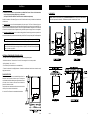
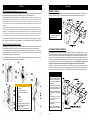
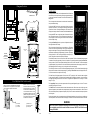
UNITED STATES STOVE COMPANY “Keeping North America Warm Since 1869” MULTI-FUEL FURNACE MODEL 8500 Approved for US and Canadian use. Safety tested and listed to UL 391-2010, ASTM E1509-04, and CSA-B366.1-11 Certified for installation in a residential or mobile home as a stand-alone or add-on furnace (ductwork connection only). TESTED & LISTED BY PORTLAND, OREGON, USA Report #: 215-S-22b-2 Owner’s Manual Please read this entire manual before installation and use of this appliance. Failure to follow these instructions could result in property damage, bodily injury, or even death. Contact your local building or fire officials about restrictions and installation inspection requirements in your area. SAVE THESE INSTRUCTIONS. French version is available for download from the U. S. Stove website: http://www.Breckwell.com/ UNITED STATES STOVE COMPANY • 227 INDUSTRIAL PARK ROAD • SOUTH PITTSBURG, TENNESSEE 37380 • WWW.USSTOVE.COM FOR TECHNICAL ASSISTANCE: PHONE: (800) 750-2723 FAX: (423) 837-2109 USSC1 Part No.: 851976 Table of Contents TABLE OF CONTENTS............................................................................................... 2 Safety Precautions............................................................................................ 3 Specifications........................................................................................................ 4 Heating Specifications...................................................................................... 4 Dimensions....................................................................................................... 4 Electrical Specifications.................................................................................... 4 Safety and EPA Compliance............................................................................. 4 Fuel Considerations.......................................................................................... 5 Installation ........................................................................................................... 5 Installation Options........................................................................................... 6 Floor Protection................................................................................................ 6 Clearances ....................................................................................................... 7 Venting Requirements...................................................................................... 8 Maximum Venting Distance.............................................................................. 8 Pellet Vent Type................................................................................................ 8 Pellet Vent Installation...................................................................................... 8 Pellet Vent Termination..................................................................................... 8 Vent Termination Clearances............................................................................ 9 Through the Wall Installation.......................................................................... 10 Through the Roof/Ceiling Installation............................................................. 10 Primary and Secondary Furnace Illustrations................................................. 11 Operation.............................................................................................................. 12 How Your Furnace Works............................................................................... 12 Damper Control Adjustment............................................................................ 12 Control Panel.................................................................................................. 13 Unit Preparation.............................................................................................. 14 Start-Up Procedure......................................................................................... 14 Shut Down Procedure..................................................................................... 14 Daily Operation............................................................................................... 15 Safety and Convenience Features................................................................. 15 Maintenance......................................................................................................... 15 Exhaust System.............................................................................................. 15 Interior Chambers........................................................................................... 16 Ash Disposal................................................................................................... 16 Hopper Cleaning............................................................................................. 16 Main Door Gaskets......................................................................................... 16 Fan Motors...................................................................................................... 16 Painted Surfaces............................................................................................ 16 Glass............................................................................................................... 16 Fall Start-Up.................................................................................................... 16 Spring Shut Down........................................................................................... 16 Yearly Servicing.............................................................................................. 16 Repair Parts DIAGRAM & List......................................................................17-18 Wiring Diagram.................................................................................................... 19 Trouble Shooting.............................................................................................. 20 Error codes......................................................................................................... 21 Flashing indicators.......................................................................................... 21 notes..................................................................................................................22-23 2USSC Safety Precautions IMPORTANT: Read this entire manual before installing and operating this product. Failure to do so may result in property damage, bodily injury, or even death. Proper installation of this furnace is crucial for safe and efficient operation. Contact your local building officials to obtain a permit and information on any additional installation restrictions or inspection requirements in your area. DO NOT throw this manual away. This manual has important operation and maintenance instructions that you will need at a later time. Always follow the instructions in this manual. Never try to repair or replace any part of the furnace unless instructions for doing so are given in this manual. All other work should be done by a trained technician. Install appliance and venting at clearances specified in this manual. DO NOT connect the pellet exhaust vent to a vent serving any other appliance or furnace. DO NOT install a flue damper in the exhaust venting system of this unit. Use of outside air is not required for this unit, but is highly recommended. If installed into a tightly constructed home, (Mobile Home) a fresh air opening of at least 2 in. diameter (150mm) into the room where the unit is installed is required. However return air make-up is required for maximum heat distribution throughout your home. This heater is designed and approved as a multi-fuel (corn or wood pellets) furnace. Use only dried shelled corn with a moisture content of 11% or less (which provides the best results). Pellet fuel used should have an ash content of 1% or less. If not, performance and efficiency of the unit will suffer, and your warranty may be voided. Never use gasoline, gasoline-type lantern fuel, kerosene, charcoal lighter fluid, or similar liquids to start or ’freshen up’ a fire in this furnace. Keep all such liquids well away from the furnace while it is in use. A working smoke detector must be installed in the same room as this product. DO NOT unplug the furnace if you suspect a malfunction. Turn the ON/OFF SWITCH to ”OFF’ and contact your dealer. Your furnace requires periodic maintenance and cleaning (see ”MAINTENANCE ”). Failure to maintain your furnace may lead to improper and/or unsafe operation. DANGER: Risk of Fire or Explosion - DO NOT BURN GARBAGE, GASOLINE, NAPTHA, ENGINE OIL, OR OTHER INAPPROPRIATE MATERIALS. Disconnect the power cord before performing any maintenance! NOTE: Turning the ON/OFF Switch to ”OFF” does not disconnect all power to the electrical components of the furnace. Allow the furnace to cool before performing any maintenance or cleaning. Ashes must be disposed of in a steel container with a tight fitting lid. The closed container of ashes should be placed on a noncombustible surface or on the ground, well away from all combustible materials, pending final disposal. The exhaust system should be checked monthly during the burning season for any build-up of soot or creosote. Creosote in your exhaust can potentially cause a chimney fire. In the event of a chimney fire, contact your fire department immediately and press the “OFF” button on your furnace. Have a clearly understood plan to handle a chimney fire. CAUTION: Keep children away. Do not touch during operation. Educate all children on the dangers of a high-temperature furnace. Young children should be supervised when they are in the same room as the furnace. A power surge protector is recommended. This unit must be plugged into a 110 - 120V, 60 Hz grounded electrical outlet. Do not use an adapter plug or sever the grounding plug. Do not route the electrical cord underneath, in front of, or over the furnace. Do not route the cord in foot traffic areas or pinch the cord under furniture. The furnace will not operate during a power outage. If a power outage does occur, check the furnace for smoke spillage and open a window if any smoke spills into the room. The feed door and ash pan must be closed and sealed during operation to keep products of combustion from escaping the furnace. Keep all seals in good condition. Never block free flow of air through the open vents of the unit. Keep foreign objects out of the hopper. The moving parts of this furnace are propelled by high torque electric motors. Keep all body parts away from the auger while the furnace is plugged into an electrical outlet. These moving parts may begin to move at any time while the furnace is plugged in. Do not place clothing or other flammable items on or near this furnace. This appliance is not intended for commercial use. WARNING: DO NOT INSTALL IN SLEEPING ROOM. CAUTION: THE STRUCTURAL INTEGRITY OF THE MANUFACTURED HOME FLOOR, WALL, AND CEILING/ROOF MUST BE MAINTAINED. USSC3 Specifications SHELLED CORN (Dry, preferably corn with 11% or less moisture content) Heating Specifications Input BTU/Hr1 50,000 to 105,000 BTU/hr. Heating Capacity2 1,200 - 2,800 sq. ft. Fuel Burn Rate 5.0 - 13.0 lbs./hr. 3 Fuel Considerations Burn Time (lowest setting) 70 hours continuous Hopper Capacity 320 lbs BTU output will vary depending on the quality and type of fuel. Use PFI listed fuels for the best results. Heating capacity will vary depending on floor plan layout of your home, degree of insulation, and the outside temperature. 3 Fuel size may effect the actual rate of fuel feed and burn times. Fuel feed rates may vary by as much as 20%. Use PFI listed fuel for best results. 1 • Optimum moisture content of corn should be 11% or less. Wet corn will rapidly deteriorate furnace components, reduce efficiency and void all warranties. Purchase a moisture tester if in doubt. • Corn must be clean and free from debris. Never burn corn right from the field. Damage caused by dirty corn is not covered by the product warranty. Ask for clean filtered, bagged corn only. Stalk parts, excessive fines and cob remnants will clog the auger. • NEVER BURN SEED CORN IN YOUR FURNACE. Seed corn is treated with chemical pesticides that are harmful or fatal if swallowed, therefore, seed corn is dangerous to have in the house, especially where children can reach it. • Never burn “Deer Corn.” It frequently contains molasses/sugars. • Store your corn supply in a dry place and keep bags or container sealed to prevent your corn from absorbing excess moisture. Test the moisture content periodically to ensure proper dryness. • There are many varieties of corn grown around the world. Each variety has unique characteristics including the shape and size of the kernel. Your furnace will burn more consistently with a small to midsize kernel corn. If the kernel size of the corn varies greatly or if you switch sources frequently, you will get a less consistent burn. Therefore, purchasing corn from the same source will help achieve a more consistent burn. DO NOT USE CORN WITH A HIGH WAX CONTENT! • Oyster shell is highly recommended for best burn operations and to reduce clinker build-up 2 Dimensions Height 43 in. [109cm] Width 28-1/2 in. [72.4cm] Depth 45 in. [114cm] Weight 250 lbs. WOOD PELLETS Electrical Specifications Electrical Rating Watts (operational) 110-120 volts, 60 HZ, 9.5 Amps 1150 (max. approx.) SAFETY AND EPA COMPLIANCE • As with corn, be consistent with your pellet supplier. Pellets will vary in content and burn characteristics from supplier to supplier. A consistent supply of pellets will result in a more consistent and efficient burn. • Check your pellets for foreign objects. Your furnace warranty will not cover damage done to your furnace due to foreign objects in the fuel supply. • Store your pellets in a dry place to prevent them from absorbing added moisture. • To decrease sawdust buildup, the hopper will need to be vacuumed out after every 6-8 bags of pellets or more often if the pellets are poor quality. You may have to screen-sift each bag of pellets if sawdust becomes a problem. • Wood Pellets vary in size and ash content from less than 1% to 3% or more. Your furnace will burn more efficiently with small to midsize pellets. Low ash content pellets will allow you to burn the furnace longer between cleanings. Only wood pellets manufactured to the Pellet Fuel Industries (P.F.I.) standard for residential pellet fuels are recommended. Performance will suffer if nonstandard pellets are used. Consult your local King reseller for more information on approved wood pellet fuel. If fans are used in the fuel storage area, they should be installed so as not to create a negative pressure in the room where your furnace is located. Your King Furnace has been safety tested and listed to UL 391-2010, ASTM E1509-04, and CSA-B366.1-11, by OMNITest Laboratories, Inc. Portland, Oregon USA. It is also exempt from EPA Phase II requirements. CAUTION: DO NOT PLACE SUCH FUELS WITHIN THE SPACE HEATER’S INSTALLATION CLEARANCES OR WITHIN THE SPACE REQUIRED FOR REFUELING AND ASH REMOVAL. 4USSC USSC5 Installation Installation Installation Options Read this entire manual before you install and use your Multi-Fuel Furnace. Failure to follow instructions may result in property damage, bodily injury, or even death! (See specific installation details for clearances and other installation requirements) Certified for installation in a Residentail Type home in the USA and Canada. Also may be installed into a Manufactured or Mobile Home. Clearances NOTE: Distance on the left-hand side of your Multi-Fuel Furnace is set at 24 inches for suitable access to the control panel and for fuel loading. This distance may be less, but not less than 7 inches. As a Primary Furnace—the unit functions independently of any other system. The “Room Air” blowers will come on when the plenum and exhaust temperatures reach a preset point programmed into the furnace’s circuit board (PCB). Unit may also be used as a stand-alone shop heater. This is the only approved installation configuration in which ductwork or return air is not required. All other configurations utilizing a ductwork system must supply return air to the appliance. As a Secondary (Add-On) Furnace—the unit aids an existing gas/electric furnace helping cut down on operation time. It is recommended that only a authorized technician install your Multi-Fuel Furnace, preferably an NFI certified specialist. Canada requires that the installation of the pellet-fuel furnace shall comply with the applicable requirements of CSA-B365. IMPROPER INSTALLATION: The manufacturer will not be held responsible for damage caused by the malfunction of a furnace due to improper venting or installation. Call (800) 750-2723 and/or consult a professional installer if you have any questions. ADDITIONAL ITEMS required FOR INSTALLATION • UL listed 3 inch or 4 inch (Depending on application) “PL” pellet venting exhaust system. • Air distribution duct work. Transition from 4.5 inch x 18.5 inch rectangle to 10 inch round is provided. • Air filter (Optional). Size: 10 x 20 x 1 • Floor Protection (If not installed on a non-combustible floor) • Fresh air for combustion: 2 inches[5cm] diameter - If installed in a manufactured / mobile home or located in a small, tightly constructed room. Floor protection This unit must be installed on a non-combustible floor surface. If a floor pad is used, it should be UL listed or equal. The floor pad or non-combustible surface should be large enough to extend a minimum of 6-inches in front, 6-inches on each side, and 1-inch behind the furnace for horizontal termination. Floor protection must extend under and 2-inches to each side of the chimney tee for an interior vertical termination. A 1 inch thick Floor Protector is recommended with installation. 6USSC USSC7 Installation Installation Venting requirements Vent termination clearances: Install vent at clearances specified by the vent manufacturer. A) Minimum 4-foot (1.22m) clearance below or beside any door or window that opens. Do not connect the pellet vent to a vent serving any other appliance or furnace. B) Minimum 1-foot (0.3m) clearance above any door or window that opens. Do not install a flue damper in the exhaust venting system of this unit. INSPECT EXHAUST VENTING (joints, seals, etc.) REGULARLY TO ENSURE THAT SMOKE AND FLUE GASES ARE NOT DRAWN INTO AND CIRCULATED BY THE AIR CIRCULATION SYSTEM. The following installation guidelines must be followed to ensure conformity with both the safety listing of this furnace and to local building codes. IMPORTANT! This unit is equipped with a negative draft system that pulls through the burn pot and pushes the exhaust out of the dwelling. If this unit is connected to a flue system other than the way explained in this manual, it will not function properly. Maximum venting distance Installation MUST include at least 3-feet of vertical pipe. This will create a natural draft to reduce the possibility of smoke or odor escaping during appliance shutdown and keep exhaust from causing a nuisance or hazard by exposing people or shrubs to high temperatures. The maximum recommend vertical venting height is 12-feet for 3-inch type “PL” vent. Total length of horizontal vent must not exceed 4-feet (this does not include the clean-out tee). Use no more than 180 degrees of elbows (two 90-degree elbows, or two 45-degree and one 90-degree elbow, etc.) to maintain adequate draft. C) Minimum 3-foot (0.91m) clearance from any adjacent building. D) Minimum 7-foot (2.13m) clearance from any grade when adjacent to public walkways. E) Minimum 2-foot (0.61m) clearance above any grass, plants, or other combustible materials. F) Minimum 3-foot (0.91m) clearance from an forced air intake of any appliance. G) Minimum 2-foot (0.61m) clearance below eves or overhang. H) Minimum 1-foot (0.3m) clearance horizontally from combustible wall. I) Must be a minimum of 3 foot (0.91m) above the roof and 2 foot (0.61m) above the highest point or the roof within 10 feet (3.05m). Pellet vent type A UL listed 3-inch or 4-inch type “PL” pellet vent exhaust system must be used for installation and attached to the pipe connector provided on the back of the furnace (use a 3-inch to 4-inch adapter for 4-inch pipe). Use 4-inch vent if the vent height is over 12-feet or if the installation is over 2,500 feet above sea level. We recommend the use of Simpson Dura-Vent® or Metal-Fab® pipe (if you use other pipe, consult your local building codes and/or building inspectors). Do not use Type-B Gas Vent pipe or galvanized pipe with this unit. The pellet vent pipe is designed to be disassembled for cleaning and should be checked several times during the burning season. Pellet vent pipe is not furnished with the unit and must be purchased separately. Pellet vent installation The installation must include a clean-out tee to enable collection of fly ash and to permit periodic cleaning of the exhaust system. 90-degree elbows accumulate fly ash and soot thereby reducing exhaust flow and performance of the furnace. Each elbow or tee reduces draft potential by 30% to 50%. VENT TERMINATION CLEARANCES All joints in the vent system must be fastened by at least 3 screws, and all joints must be sealed with HI-TEMP RTV silicone sealant to be airtight. The area where the vent pipe penetrates to the exterior of the home must be sealed with silicone or other means to maintain the vapor barrier between the exterior and the interior of the home. Vent surfaces can get hot enough to cause burns if touched by children. Noncombustible shielding or guards may be required. Pellet vent termination Do not terminate the vent in an enclosed or semi-enclosed area, such as; carport, garage, attic, crawl space, under a sun deck or porch, narrow walkway, or any other location that can build up a concentration of fumes. The termination must exist above the outside air inlet elevation. The termination must not be located where it could become plugged by snow or other materials. 8USSC USSC9 Installation THROUGH THE WALL INSTALLATION (Recommended installation) To vent the unit through the wall, connect the pipe adapter to the exhaust motor adapter. If the exhaust adapter is at least 24-inches above ground level, a straight section of pellet vent pipe can be used through the wall. Your furnace dealer should be able to provide you with an installation kit, which will include a wall thimble that will allow the proper clearance through a combustible wall. Once outside the structure, a 3-inch clearance should be maintained from the outside wall and a clean out tee should be placed on the pipe with a 90-degree turn away from the house. At this point, a 3-foot (minimum) vertical section of pipe should be added with a horizontal cap, which would complete the installation. A support bracket should be placed just below the termination cap or one every 4-feet to make the system more stable. If you live in an area that has heavy snowfall, it is recommended that the installation be taller than 3-feet to get above the snowdrift line. This same installation can be used if your furnace is below ground level by simply adding the clean-out section and vertical pipe inside until ground level is reached. With this installation you have to be aware of the snowdrift line, dead grass, and leaves. We recommend a 3-foot minimum vertical rise on the inside or outside of the house. The “through the wall” installation is the least expensive and simplest installation. Never terminate the end vent under a deck, in an alcove, under a window, or between two windows. We recommend Simpson Dura-Vent® or Metal-Fab® kits. Installation PRIMARY FURNACE This appliance requires the installation of a cold air return duct system. The return air will provide a better distribution of warm air throughout your home, making the unit much more efficient than if installed without a return system. This appliance must be installed by experienced personnel and in accordance with the instructions of the manufacturer and in a manner acceptable to the authority having jurisdiction. When required by the authority having jurisdiction, such personnel must be licensed to perform this service. All installation configurations require the use of a return air system unless specified otherwise herein. Through the roof/Ceiling Installation When venting the furnace through the ceiling, the pipe is connected in the same manner as a wall installation, except the clean-out tee is always on the inside of the house, and a 3-inch adapter is placed in front of the clean-out tee. You must use proper ceiling support flanges and roof flashing (supplied by the pipe manufacturer; follow the pipe manufacturer’s directions). It is important to note that if your vertical run of pipe is more than 15-feet, the pellet vent pipe size should be increased to 4-inches in diameter. Do not exceed more than 4-feet of pipe on a horizontal run and use as few elbows as possible. If an offset is required, it is better to install 45-degree elbows rather than 90-degree elbows. SECONDARY (ADD-ON) FURNACE When installed as a secondary furnace, it may only be connected to the ductwork of the existing primary furnace (Gas, Electric, etc.). It should not be wired in conjunction with the existing furnace’s circuitry. A Duct Damper must be installed between the air discharge of the 8500 furnace and the primary furnace. This duct damper prevents the air of the primary furnace from back flowing to the secondary furnace. The damper must be a mechanical (spring return) style with a simple closure switch to determine if the damper is opened or closed. The damper will connect to the 8500’s printed circuit board (PCB) as a signal connection only. See wiring diagram in this manual. The PCB will not supply power to an electronic damper requiring a power supply. This power supply must come from a different source. CAUTION: Do not connect your furnace’s ductwork to the cold air return duct of your existing furnace because a possibility exists of components of the central furnace overheating and causing it to operate other than intended. Only connect to ductwork that is in good condition. Never direct the air flow from the exisiting furnace thru the Add-On furnace. CAUTION: MAINTAIN COMBUSTION AIR SUPPLY TO BOTH FURNACES, AIR STARVATION IS DANGEROUS. OPERATE THE EXISTING FURNACE PERIODICALLY TO ENSURE THAT IT WILL OPERATE SATISFACTORILY, WHEN NEEDED. 1 Vertical Cap 2 Storm Collar 3 Adjustable Roof Flashing 4 Cathedral Ceiling Support Box 5Pipe 6 45° Elbow 7 90° Elbow 8 Horizontal Cap 9 Wall Thimble 10 Black Ceiling Support Firestop Spacer 11 Single Tee with Clean-Out Adapter 12 Tee Support Bracket 13 Double Tee with Clean-Out Adapter 10USSC DO NOT RELOCATE OR BYPASS ANY OF THE SAFETY CONTROLS IN THE EXISTING FURNACE INSTALLATION. REFER TO THE MANUFACTURER’S INSTRUCTIONS OF YOUR EXISTING FURNACE. DO NOT USE DUCT ELBOWS HAVING AN INSIDE RADIUS OF LESS THAN 150mm (6 in.). DO NOT CONNECT TO A DOWN FLOW FURNACE. DO NOT CONNECT DUCTWORK SO THAT A REVERSE FLOW IS POSSIBLE. USSC11 Component Location Operation Control Panel CLEANOUT TOOL Turning the furnace OFF/ON, as well as adjustments for the fuel feed rate and room fan speed are performed by pressing the appropriate button(s) on the control panel which is located on the lower left-hand side of your King furnace. This unit can operate in either automatic or manual mode. Automatic mode has pre-set default settings. ASH CLEANOUTS Pressing the “ON” button on the control panel will begin the start-up sequence for the furnace. Fuel will begin to feed through the auger feed system after 3 minutes. Pressing and holding the “ON” button will rotate the auger continuously until button is released, which feeds additional fuel. Heat Range Room Fan Draft Fan Pressing the “OFF” button on the control panel will cause the furnace to enter its shut-down sequence. The fuel feed system will stop pulling fuel from the hopper and, once the fire goes out and the furnace cools down, the fans will stop running. Pressing the “Heat Range” arrows, up or down, will adjust the amount of fuel being delivered to the burnpot. STAINLESS STEEL BAFFLE EXHAUST CLEANOUT (located behind the ash pan) This unit comes preset from the factory to burn shelled corn. The display will show a “Cr” in front of the heat setting. If burning only wood pellets, this setting must be changed. To change, press and hold the heat range up and down buttons simultaneously for approximately 2-3 seconds. The display will change from “Cr” to “Pr”. If burning a pellet(50%) and corn(50%) mix, the “Cr” setting will work the best for optimum performance. Aux. Auto ON OFF Auger Delay Mode Manual The draft fan (exhaust) will come on as soon as the “ON” button is pressed. The fan will automatically adjust its speed in accordance to the heat range setting. However, this speed can be manually operated by pressing the “Draft Fan” arrows up or down. “Draft Fan” when pressed, the display will show “Df-A”, which is automatic. Press the arrows again to adjust fan speed. When the furnace is in the manual mode, the optional thermostat will not properly control the unit. When adjusting the Draft Fan setting, try only 1 setting above or below the heat setting. The room fan(s) will come on once the unit has reached operating temperature. The room fans will automatically adjust their speed in accordance with the heat range setting. By pressing the “Room Fan” buttons, the display will show “RfA” which is automatic or how many fans are running. Door Handle and Fuel Latch Assembly Insert door handle into door. From rear side of door, place a 1/2” washer over the threaded part of the handle, then attach the lock nut. Tighten the nut, then back off 1/4 turn to allow free operation of the handle. (1) Door Handle (1) 1/2” Washer (1) 1/2” Lock Nut With two 1/4-20 x 3/4 hex bolts, attach the door latch to the door latch mounting bracket on the left side of the door frame as illustrated. The slot in the bracket and latch are for door seal adjustment. Make the proper adjustments, then tighten the nuts. The door’s gasket should be snug against the door frame on the furnace. (1) Feed Door Latch (2) 1/4-20 x 3/4 Hex Bolt (2) 1/4-20 Kep Nut 12USSC The “Aux” button is for Agitator operation. When the unit is “OFF”, pressing the “Aux” arrows will rotate the agitator for easy removal for cleaning. The agitator, when in Automatic mode, will operate at set intervals. However, these can be changed by pressing the arrows on the “Aux” button. The agitator can be adjusted from 0 to 9, setting “0” is off and setting “9” is high. The “Auger Delay” button can be used to pause rotation of the Auger and Agitator for approx. 1 minute. This can be cancelled by pressing the “ON” button. The “Mode” button is used to switch between manual and automatic mode. When in auto mode, the fans, auger, and agitator will operate at preset intervals unless changed manually using the buttons mentioned above. When in manual mode, the draft fan (exhaust) will operate at full speed (100%), so the air must be controlled with the damper just below the viewing door. During normal operation, this unit constantly monitors itself for potential problems. In the event of an error condition, the unit will stop and an error code will be shown in the display. See the list of error codes found at the end of this manual. WARNING RISK OF FIRE - DO NOT operate with fuel-loading or ash-removal doors open. DO NOT store fuel or other combustible material within marked installation clearances. INSPECT and CLEAN flues and chimneys REGULARLY. USSC13