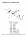
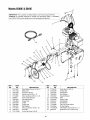
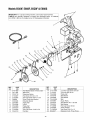
1
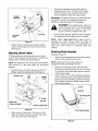
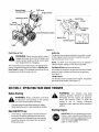
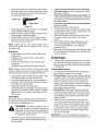
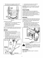
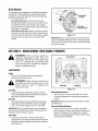
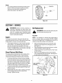
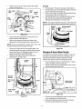
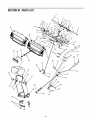
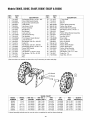
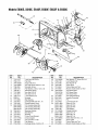
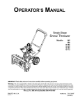
OPERATOR'S
MANUAL
SNOW THROWER
MODELS
E600E,
E640F,
E660G,
IMPORTANT:
READ SAFETY
RULES AND INSTRUCTIONS
$610E
E660F
E6COF
CAREFULLY
Warning:
This unit is equipped with an internal combustion engine and should not be used on or near any unimproved forest-covered,
brush-covered or grass-covered land unless the engine's exhaust system is equipped with a spark arrester meeting applicable local or state
laws (if any). If a spark arrester is used, it should be maintained in effective working order by the operator. In the State of California the
above is required by law (Section 4442 of the California Public Resources Code). Other states may have similar laws. Federal laws apply
on federal lands. A spark attester for the muffler is available th rough your nearest engine authorized service dealer or contact the service
department,
P.O. Box 361131 Cleveland, Ohio 44136-9722.
MTD LLC, P.O. BOX 361131 CLEVELAND,
OHIO 44136-9722
FORM NO. 769-00292
PRINTED iN U.S.A.
(5/2002)
TABLEOFCONTENTS
Content
Page
important Safe Operation Practices ........................................................................
3
Loose Parts & Hardware Pack .................................................................................
5
Assembling Your Snow Thrower .............................................................................
7
Know Your Snow Thrower .......................................................................................
10
Operating Your Snow Thrower ................................................................................
11
Making Adjustments ................................................................................................
13
Maintaining Your Snow Thrower .............................................................................
14
Service ....................................................................................................................
15
Off-Season Storage .................................................................................................
17
Troubleshooting
18
......................................................................................................
Parts List .................................................................................................................
19
FINDINGMODELNUMBER
This Operator's Manual is an important part of your new snow thrower. It will help you assemble, prepare and
maintain the unit for best performance. Please read and understand what it says.
O
copy the information from it in the space provided below. The information on the model plate is very
efore you start assembling your new equipment, please locate the model plate on the equipment and
important if you need help from our Customer Support Department or an authorized dealer.
You can locate the model number by standing behind the unit in the operating position and looking down at the rear
frame below the engine. A sample model plate is explained below. For future reference, please copy the model
number and the serial number of the equipment in the space below.
(Model Number)
(Serial Number)
P. O. BOX 361131
CLEVELAND,OH
44136
330-220-4683
_, www, mtuproaucts.com
Copy the model number here:
Copy the serial number here:
800-800-7310,
ENGINEINFORMATION
The engine manufacturer is responsible for all engine-related issues with regard to performance, power-rating,
specifications, warranty and service. Please refer to the engine manufacturer's Owner's/Operator's Manual packed
separately with your unit for more information.
CALLINGCUSTOMER
SUPPORT
Please do NOT return theunit to the retailer from whichit waspurchased, withoutfirst contactingCustomerSupport.
Should you have difficulty assembling this product or have any questions regarding the controls, operation or
maintenance of this unit, please call the Customer Support Department.
Call 1- (330) 220-4MTD (4683) or 1- (800) 800-7310 to reach a Customer Support representative.
Please have your unit's model number and serial number ready when you call. See previous section to
locate this information. You will be asked to enter the serial number in order to process your call.
SECTION1: IMPORTANT
SAFEOPERATION
PRACTICES
This symbol points out important safety instructions, which if not followed, could endanger the personal
safety and/or property of yourself and other& Read and follow all instructions in this manual before
attempting to operate this machine. Failure to comply with these instructions may result in personal
injury. When you see this symbol--heed its warning.
WARNING:
Engine Exhaust, some of its constituents,
contain or emit chemicals known to the State of California
other reproductive harm.
and certain vehicle components
to cause cancer, birth defects or
DANGER:
This machine was built to be operated according to the rules for safe operation in this
manual. As with any type of power equipment, carelessness or error on the part of the operator can
result in serious injury.This machine is capable of amputating hands and feet and throwing objects.
Failure to observe the following safety instructions could result in serious injury or death.
TRAINING
1.
2.
3.
4.
5.
6.
7.
Read, understand, and follow all instructions on the
machine and in the manual(s) before attempting to
assemble and operate. Keep this manual in a safe place
for future and regular reference and for ordering
replacement parts.
Be familiar with all controls and their proper operation.
Know how to stop the machine and disengage them
quickly.
Never allow children under 14 years old to operate this
machine. Children 14 years old and over should read and
understand the operation instructions and safety rules in
this manual and should be trained and supervised by a
parent.
Never allow adults to operate this machine without
proper instruction.
Thrown objects can cause serious personal injury. Plan
your snow-throwing pattern to avoid discharge of material
toward roads, bystanders and the like.
Keep bystanders, helpers, pets and children at least 75
feet from the machine while it is in operation. Stop
machine if anyone enters the area.
Exercise caution to avoid slipping or failing, especially
when operating in reverse.
7.
8.
9.
g.
h.
PREPARATION
1.
2.
3.
4.
5.
6.
Thoroughly inspect the area where the equipment is to
be used, Remove all doormats, newspapers, sleds,
boards, wires and other foreign objects, which could be
tripped over or thrown by the auger/impeller.
Always wear safety glasses or eye shields during
operation and while performing an adjustment or repair to
protect your eyes, Thrown objects which ricochet can
cause serious injury to the eyes.
Do not operate without wearing adequate winter outer
garments, Do not wear jewelry, long scarves or other
loose clothing, which could become entangled in moving
parts. Wear footwear which will improve footing on
slippery surfaces.
Use a grounded three-wire extension cord and
receptacle for all units with electric start engines.
Adjust collector housing height to clear gravel or crushed
rock surfaces.
Disengage all clutch levers before starting the engine.
Never attempt to make any adjustments while engine is
running, except where specifically recommended in the
operator's manual.
Let engine and machine adjust to outdoor temperature
before starting to clear snow.
To avoid personal injury or property damage use extreme
care in handling gasoline. Gasoline is extremely
flammable and the vapors are explosive. Serious
personal injury can occur when gasoline is spilled on
yourself or your clothes, which can ignite. Wash your skin
and change clothes immediately.
a. Use only an approved gasoline container.
b. Extinguish all cigarettes, cigars, pipes and other
sources of ignition.
c. Never fuel machine indoors.
d. Never remove gas cap or add fuel while the
engine is hot or running.
e. Allow engine to cool at least two minutes before
refueling.
f.
Never over fill fuel tank. Fill tank to no more than
i.
j.
Y2inch below bottom of filler neck to provide space
for fuel expansion.
Replace gasoline cap and tighten securely.
If gasoline is spilled, wipe it off the engine and
equipment. Move machine to another area. Wait 5
minutes before starting the engine.
Never store the machine or fuel container inside
where there is an open flame, spark or pilot light
(e.g. furnace, water heater, space heater, clothes
dryer etc.).
Allow machine to cool at least 5 minutes before
storing.
OPERATION
1.
2.
3.
Do not put hands or feet near rotating parts, in the auger/
impeller housing or discharge chute. Contact with the
rotating parts can amputate hands and feet.
The auger/impeller clutch lever is a safety device. Never
bypass its operation. Doing so makes the machine
unsafe and may cause personal injury.
The clutch levers must operate easily in both directions
and automatically return to the disengaged position when
released.
4. Never
operate
witha missing
ordamaged
discharge
Contact
yourdealerortelephone
1-800-800-7310
for
chute.Keepallsafety
devices
inplaceandworking.
assistance
andthename
ofyournearest
servicing
dealer.
5. Never
runanengine
indoors
orinapoorly
ventilated
area.Engine
exhaust
contains
carbon
monoxide,
an
odorless
anddeadly
gas.
MAINTENANCE
ANDSTORAGE
6. Donotoperate
machine
whileundertheinfluence
of
1. Never tamper with safety devices. Check their proper
alcohol
ordrugs.
operation regularly. Refer to the maintenance and
7. Muffler
andengine
become
hotandcancause
aburn.Do
adjustment sections of this manual.
nottouch.
2.
Before cleaning, repairing or inspecting machine
8. Exercise
extreme
caution
whenoperating
onorcrossing
disengage all clutch levers and stop engine. Wait until the
gravelsurfaces.
Stayalertforhidden
hazards
ortraffic.
auger/impeller come to a complete stop. Disconnect the
9. Exercise
caution
whenchanging
direction
andwhile
spark plug wire and ground against the engine to prevent
operating
onslopes.
unintended starting.
10. Planyoursnow-throwing
pattern
toavoiddischarge
3. Check bolts and screws for proper tightness at frequent
towards
windows,
walls,carsetc.Thus,avoiding
intervals to keep the machine in safe working condition.
possible
property
damage
orpersonal
injurycaused
bya
Also, visually inspect machine for any damage.
ricochet.
4.
Do not change the engine governor setting or over-speed
11. Never
directdischarge
atchildren,
bystanders
andpets
the engine. The governor controls the maximum safe
orallowanyone
infrontofthemachine.
operating speed of the engine.
12. Donotoverload
machine
capacity
byattempting
toclear
5.
Snow thrower shave plates and skid shoes are subject to
snowattoofastofa rate.
wear and damage. For your safety protection, frequently
13. Never
operate
thismachine
without
goodvisibility
or
check all components and replace with original
light.Always
besureofyourfooting
andkeepafirmhold
equipment manufacturer's (OEM) parts only. "Use of
onthehandles.
Walk,neverrun.
parts which do not meet the original equipment
14. Disengage
power
totheauger/impeller
when
specifications may lead to improper performance and
transporting
ornotinuse.
compromise safety!"
15. Never
operate
machine
athightransport
speeds
on
6. Check clutch controls periodically to verify they engage
slippery
surfaces.
Lookdownandbehind
andusecare
and disengage properly and adjust, if necessary. Refer to
wheninreverse.
the adjustment section in this operator's manual for
16. Ifthemachine
should
starttovibrate
abnormally,
stopthe
instructions.
engine,
disconnect
thesparkplugwireandground
it
7.
Maintain or replace safety and instruction labels, as
against
theengine.
Inspect
thoroughly
fordamage.
necessary.
Repair
anydamage
before
starting
andoperating.
8.
Observe proper disposal laws and regulations for gas,
17. Disengage
allclutch
levers
andstopengine
before
you
oil, etc. to protect the environment.
leavetheoperating
position
(behind
thehandles).
Wait
untiltheauger/impeller
comes
toacomplete
stopbefore 9. Prior to storing, run machine a few minutes to clear snow
from machine and prevent freeze up of auger/impeller.
unclogging
thedischarge
chute,
making
any
10.
Never store the machine or fuel container inside where
adjustments,
orinspections.
there is an open flame, spark or pilot light such as a water
18. Never
putyourhandinthedischarge
orcollector
heater, furnace, clothes dryer etc.
openings.
Always
usetheclean-out
toolprovided
to
11.
Always refer to the operator's manual for proper
unclog
thedischarge
opening.
Donotunclog
discharge
instructions on off-season storage.
chutewhileengine
isrunning.
Shutoffengine
andremain
behind
handles
untilallmoving
partshavestopped
WARNING-- YOURRESPONSIBILITY:
before
unclogging.
Restrict the use of this power machine to persons who
19. Useonlyattachments
andaccessories
approved
bythe
understand and follow the warnings and
manufacturer
(e.g.wheelweights,
tirechains,
cabsetc.). read,
instructions
in this manual and on the machine. The
20. Ifsituations
occurwhicharenotcovered
inthismanual,
safety
labels
are shown below for your reference.
usecareandgoodjudgment.
1.10_ AWAYFROMROTATIM6
IMPELLI_
ANDAU6BR.COHTACT
WT'C4
IrHI_LLER
OR
ALIBRCAN,rH_UTATO
HANDS
ANDOG:-r,
2, USECLFJLN-OGT
TOOLTOUNCLOG
DI$CILANGE
$HUIT,
3, DISEH6ACE
CLUTCH
LEVIERS
510PENGINE,
ANDH_IINN gBHIfOFIAOGLE$
UN11LALL
MOIfloGPARTSHAVE
STO_W DETOHE
UNCLOGGING
OR$BTIOGIOG
MACHINE,
4, TOAVOID11411011114
OBJECTS
INJURIES,
I1_ DIRECT
DIS_E
ATi?5"rANDERS,
USEerlM CALl,ON
IV'HBN
OUHI6
ON
6RAVELSURFACES,
. R_D OPERATOR'SMANUAL,
ContentsOfHardwarePack
Lay out the hardware according to the illustration for identification purposes. Part numbers are shown in
parentheses. (Hardware pack may contain extra items which are not used on your unit.)
A_
cJ
ATTACHING THE CHUTE ASSEMBLY
ATTACHING THE HANDLES
r__-q [Z3
! i
C__]
--
Bolts
-- Hex
He,
Bo,t.,
5/16-18
x2
-
-
(710-04039)
(784-5599)
Handle Tabs
N
r'-]
i
-
Hex Bolts
5/16-18 xx 3/4"
5/16-18
(710-3008)
©©
-o.
_
114-20x 3/4"
Lock Washers
(736-0119)
Carriage Bolts
5116-18 x 1-1/2"
(710-0262)
©©
Chute Flange
Keepers
(731-0851 A)
5116" I.D.
Cupped Washers
(736-0242)
(____
D
Hex Lock Nuts
1/4-20 Thread
(712-3027)
J ATTACHING THE CHUTE DIRECTIONAL
CONTROL
Hex Nuts
5116" Thread
(712-3068)
S_
O
O
O
Ferrule
(711-0677)
AUGER
O
li
Flat Washers
5/16"Thread
(712-3010)
F
BOLTS*
Shear Bolts
(710-0890A)
Hex Lock Nuts
@
@
O
_
5/16" I.D.
Cupped Washers
(736-0242)
5/16" LD. x 5/8" O.D. Hair Pin Clip
(736-0275)
(714-0104)
SHEAR
318"
I.D. x 5/8" O,D.
Flat Washers
(736-0185)
O
Hex Nut
ATTACHING
SHIFT ROD
AND CLUTCH THE
CABLES
oo
E_
O
5/16"Thread(712.0429)
J
Hair Pin Clip
(714-0104)
"Z" FITTING NUTS
Jam Nuts
#10-24 Thread
(712-0121)
(_
_)
The augers are secured to the spiral shaft with two shear bolts and hex lock nuts. If you hit a hard foreign
object or an ice jam, the snow thrower is designed so that the bolts may shear. These two spare shear bolts
and nuts are provided for your convenience.
IMPORTANT: NEVER replace the auger shear bolts with standard hex bolts. Any damage to the auger gearbox
or other components as a result of doing so will NOT be covered by your snow thrower's warranty.
SECTION2: ASSEMBLING
YOURSNOWTHROWER
LooseParts
Figure 1 shows parts of the snow thrower packed loose
in the carton. You will need these parts along with
hardware from the hardware pack, illustrated on the
next page, to assemble the equipment. Identify the
loose parts before proceeding to assemble.
Assembly Tips: For convenience in assembly, remove
the chute from the carton and lay it on top of the engine.
Do not unwrap the chute till you have installed the
handle panel and the clutch cables.
AttachingHandle
Handle Panel
/
NOTE: All references to right or left side of the snow
thrower are determined from behind the unit in the
operating position. The "operator's position" is defined
as standing directly behind the snow thrower, facing the
handle panel
(Hardware Group A)
L..o.Sion
•
Place right handle in position against the snow
thrower so the flat side of the handle is against the
snow thrower. Secure bottom hole in handle to
snow thrower using 3/4" hex bolt and lock washer.
Do not tighten at this time. See Figure 2.
2" Hex
Chute Directional
Control
Shift Rod
Clean-out
Discharge
Chute
Guide
Washers
3/4" Hex
Bolt
Figure 2
Figure 1
1.
2.
3.
4.
5.
6.
7.
8.
Right and Left Handles
Handle Panel Assembly
Chute Assembly
Chute Directional Control Assembly
Shift Rod
Hardware Pack
Clean-out Tool*
Extension Cord*
* This item is fastened with a cable tie to the rear of
•
•
the Auger Housing at the factory. Cut the cable tie
before operating the snow thrower.
•
ToolsRequiredForAssembly
1.
2.
,_
Pair of pliers
Two adjustable wrenches
and
ground it against
the engine
prevent
WARNING:
Disconnect
spark to
plug
wire
unintended starting.
•
Place handle tab over the upper hole on the handle
so the curve in the handle tab matches the curve of
the handle. See Figure 2. Secure to the snow
thrower using 2" hex bolt and lock washer; do not
tighten at this time. Repeat on the other side. Do
not tighten at this time.
Place the handle panel in position between the two
handles. To hold the handle panel in place, depress
both controls against the handles. While continuing
to hold the right control, release the left control (the
auger control lock will keep left control engaged).
See Figure 3.
Fasten right side of the handle panel by inserting
two carriage bolts through handle and handle panel
(bolts must go through both the plastic and metal
parts of the handle panel). See Figure 3. Secure
with cupped washers (cupped side against handle
panel) and lock nuts.
Repeat on the other side.
•
Cupped
Thread the coupling end of the cable onto the
threaded portion of the "Z" fitting until the rubber
bumper (located on the underside of the clutch
lever) only lightly contacts the upper handle.
IMPORTANT:The cable should have very little slack, but
should NOT be tight. An overtightened cable may
prohibit the auger and drive from disengaging.
prohibit
the auger
and drive fromthe
disengaging
WARNING:
Over-tightening
cable may
and compromise the safety of the snow
thrower. Do NOT overtighten the cable.
_1_
Lock Nuts
•
Bolts
Figure 3
Tighten the four hex bolts used earlier to attach
bottom of the handles to the snow thrower frame.
See Figure 2.
"Z" fittings with jam nuts are inserted in each control
lever (on the handle panel) at the factory. To attach the
cables to the "Z" fittings, proceed as follows:
NOTE: Two extra jam nuts are included in the hardware
pack (Group F) in the event either are lost during
shipping.
Thread the jam nuts all the way up each of the ";£'
fittings, toward the handle panel. See Figure 4.
Control
NOTE: Refer to AugerControlTest on page 12 prior to
operating your snow thrower. Read and follow all
instructions carefully and perform all adjustments to
verify your snow thrower is operating safely and
properly.
AttachingChuteAssembly
AttachingControlCables
•
Once properly adjusted, tighten the jam nut against
the coupling end of the cable to lock it in position.
Lever
Handle
Panel
(Hardware Group C)
•
Place the chute assembly over the chute opening
with the chute facing front of the unit.
NOTE: Make sure that the chute cables are
straightened while assembling the chute.
Place the chute flange keeper (flat side down)
beneath lip of chute assembly as shown in Figure
5.You will find the chute flange keepers in group C
of the hardware pack.
Insert 1/4-20 x .75" hex bolt and flange nut (group
C of the hardware pack) up through chute flange
keeper and chute assembly as shown in Figure 5.
Do not tighten at this time. Rotate chute to install
all the flange keepers.
\\
Chute
Hex Bolt
Hex Flange Nut
_'Z"
Fitting
Jam Nut
Make Sure
Cable Is Straight
Cable Coupling End
Figure 4
\
Make certain all cables are in the grooves of the
cable roller guides located in the lower rear of the
unit, one on each side. See Figure 2.
J
Chute Flange Keeper
\
J
Figure 5
After assembling all three chute flange keepers,
tighten, then back off 1/4 turn to allow easier
movement of the chute. Use two 7/16" wrenches.
AttachingChuteDirectionalControl
Hairpin
(Hardware Group D)
Clip_
•
Thread one hex nut about halfway onto eye bolt on
the chute directional control.
•
Insert eye bolt through the hole provided in the left
handle. See Figure 6.
Secure with cupped washer (cupped side against
the handle) and other hex nut. Do not tighten until
after attaching the other end of the chute directional
control.
•
Chute
Directional
Control
\
_Lower
Chute
Bracket
Flat
Washers
Figure 8
•
•
•
Adjust the chute bracket so that the spiral on the
chute directional control fully engages the teeth on
the chute assembly.
Tighten nuts on the lower chute bracket securely.
Tighten hex nut on the eye bolt on chute directional
control.
AttachingShiftRod
Eye Bolt
(Hardware Group B)
IMPORTANT: Attach the shift rod and clutch cables as
Figure 6
To align the spiral on the chute directional control,
you may have to loosen the carriage bolts and hex
lock nuts securing lower chute bracket to the
extension on the left side of the chute assembly.
See Figure 7.
follows. Then check the adjustments and make any
final adjustments necessary before operating your
snow thrower. Failure to properly follow the instructions
may cause damage to the snow thrower.
•
•
Carriage
Bolts
•
•
Hex Lock
Nuts
Lower Chute f
Bracket
Figure 7
•
•
Place one flat washer on the end of the chute
directional control, then insert the end of the control
into the hole in the plastic bushing in the lower
chute bracket.
Place another flat washer on the end of the chute
directional control, and insert hairpin clip into hole in
the end of control. See Figure 8.
•
Place the shift lever (on the handle panel) in the
sixth (6) speed position (all the way forward).
Place the bent end of the shift rod into the hole in
the shift arm assembly. Secure with flat washer and
hairpin clip. See Figure 9.
Start threading the ferrule onto the other end of the
shift rod. Push down on the shift red (and shift arm
assembly) as far as it will go.
Thread the ferrule onto the shift red until the ferrule
lines up with the upper hole in the shift lever
(beneath the handle panel). Insert the ferrule into
the upper hole in the shift lever from the left side
when adjustment is correct. Secure with flat washer
and hairpin clip.
Check for correct adjustment of the shift red as
instructed in the under the heading Traction Central
andShiftLeveron page 13 before operating the snow
thrower.
.Lower Handle
LeLamp
Wire
ad
-Shift Rod
Shift Arm
Assembly
j
Hairpin Clip
Figure 10
Figure 9
LampWiring
NOTE: A lamp is an optional feature of some model
snow throwers and is NOT standard equipment. On
models so equipped, a lamp will either be installed on
the dash panel at the factory OR packaged separately
as a Kit within the carton, depending on the model
If so equipped, wrap the wire from the lamp down
the right handle until the wire can be plugged into
the alternator lead wire located under the fuel tank.
See Figure 10. Lamp wire must not interfere with
any controls or cables.
If your unit is not equipped with a lamp, contact
Customer Support as instructed on page 2 for
information regarding price and availability.
Snow Thrower Model
Electric Light Kit
E600E, E640F, E6COF,
OEM-390-255
E660F & E660G
NOTE:
The engine found on snow thrower model
$6 IOE is NOT equipped with an alternator and therefor
can NOT accept a light kit.
GasandOil
After assembly, service engine with gasoline, and
check oil level as instructed in the engine manual.
SECTION3: KNOWYOURSNOWTHROWER
OperatingControls
their
proper operation.
Know
how
stop the
WARNING:
Be familiar
with
all to
controls
and
machine and disengage them quickly.
Shift Lever
The shift lever is located in the center of the handle
panel. The shift lever may be moved into one of eight
positions. Run engine with throttle in the fast position.
Use the shift lever to determine ground speed.
Forward: There are six speeds. Position one (1) is the
slowest. Position six (6) is the fastest.
Reverse: There are two reverse (R) speeds R1 and R2.
The "R2" closest to the operator (all the way back) is the
faster of the two.
Auger Control
The auger control is located on the left handle. Squeeze
the control to engage the augers; release to stop the
augers. The traction control must also be released.
Traction / Auger Control Lock
The traction control is located on the right handle.
Squeeze the control to engage the wheel drive.
Release to stop.
This same control also locks the auger control so you
can turn the chute directional control without
interrupting the snow throwing process. If the auger
control is engaged with the traction control engaged,
the operator can release the auger control (on the left
handle) and the augers will remain engaged. Release
the traction control to stop both the augers and wheel
drive (auger control must also be released).
ChuteDirectionalControl
The chute directional control is located on left hand side
of the snow thrower.To change the direction in which
snow is thrown, rotate chute directional control as
follows:
•
•
Clockwise to discharge to the left.
Counterclockwise to discharge to the right.
Traction/Auger
Control Lock .-------.=
Shift Lever
Auger Control
f
Discharge Chute
Choke
Chute
Clean-out Tool
_.=_Spark
,_
_,
_
_
\
Plug
_
_'_
_l_
Prirner
_b/f !_SF_'<_
_ ,F._'_J
RscloilStarter
Handle
Chute Directional Control
,gnltion
Throttle Control
I
Open -_D.
I Fuel Shut_Off
Valve
I
Auger
Figure 11
ChuteClean-outTool
IgnitionKey
The ignition key must be inserted in the switch in order
for the engine to start. Remove the ignition key when
the snow thrower is net in use.
WARNING:
Never use your hand to clear a
clogged discharge chute. Shut off engine and
remain behind handles until all moving parts
have stopped before unclogging.
NOTE: Do NOT "turn" the ignition key in an attempt to
start the engine. Doing so may cause it to break.
The chute clean-out tool (see Figure 11) isdesigned to
clear a clogged discharge chute. Refer to OperatingYour
SnowThroweron page 12 for detailed instructions on how
toproperly use the chute clean-out tool.
FuelShut-0ff Valve (optional equipment)
On models so equipped, the fuel shut-off valve, located
under fuel tank, controls fuel-flow from the gas tank.
See Figure 11.
Throttle Control
The throttle control is located on the engine. It regulates
the speed of the engine. See Figure 11.
SECTION4: OPERATING
YOURSNOWTHROWER
BeforeStarting
i_
_b
•
all
instructions and
on theand
machine
WARNING:
Read,warnings
understand,
follow
and in this manual before operating.
engine
is hot or running.
Extinguish
cigarettes, cigars, pipes and other sources of
ignition.
The spark plug wire was disconnected for safety.
Attach spark plug wire to spark plug before starting.
StartingEngine
GasAnd0il Fill-up
•
handling gasoline.
extremely
WARNING:
Use Gasoline
extreme iscare
when
flammable and the vapors are explosive.
Never fuel machine indoor or while the
IMPORTANT: Prior to operating your snow
thrower, read, understand and follow ALL
instructions to perform adjustments found
under the heading AugerControlTeston
page 12 of this manual.
At the factory, a plastic cup is inserted inside the
fuel tank's fill opening (beneath the fuel cap) to
prevent debris from entering the fuel tank during
assembly. Remove and discard this cup before
filling up the tank.
10
Attach spark plug wire to spark plug. Make certain
the metal loop on end of the spark plug wire (inside
the boot) is fastened securely over the metal tip on
the spark plug. See Figure 12.
_Rubber
•
•
Boot
•
Figure 12
•
•
•
•
•
Make certain the fuel shut-off valve, if so equipped,
is in the OPEN (vertical) position.
Make certain the auger and traction controls are in
the disengaged (released) position.
Move throttle control up to FAST position. Insert
ignition key into slot. Be certain it snaps into place.
Do not turn key. See Figure 11.
•
•
NOTE: Engine will not start unless ignition key is
inserted into ignition slot in carburetor cover. Do not
turn ignition key.
•
RecoilStarter:
•
•
•
•
Rotate choke knob to FULL choke position (cold
engine start).
If engine is warm, place choke in OFF position
instead of FULL.
If your home wiring system is not a three-wire
grounded system, de not use this electric starter
under any conditions.
If your home electrical system is grounded, but
a three-hole receptacle is not available, one should
be installed by a licensed electrician before using
the electric starter.
If you have a grounded three-prong receptacle,
proceed as follows.
Rotate choke knob to OFF position.
Connect power cord to switch box on engine. Plug
the other end of power cord into a three-prong 120volt, grounded, AC receptacle.
Push starter button to crank engine. As you crank
the engine, move choke knob to FULL choke
position.
When engine starts, release starter button, and
move choke gradually to OFF. If engine falters,
move choke immediately to FULL and then
gradually to OFF.
When disconnecting the power cord, always unplug
from the three-prong receptacle first, and then from
the snow thrower.
ToStopEngine
•
Push primer button three or four times for cold
engine start.
If engine is warm, push primer button once only.
To stop engine, remove the ignition key. Do not turn
key. Disconnect the spark plug wire from the spark
plug to prevent accidental starting while equipment
is unattended.
NOTE: Always cover vent hole in primer button when
pushing. Additional priming may be necessary for first
start if temperature is below 15 degrees Fahrenheit.
To preventstarter freeze-up:
•
•
•
•
•
•
Grasp starter handle and pull rope out slowly, until it
pulls slightly harder. Let rope rewind slowly.
Pull starter handle rapidly. Do not allow handle to
snap back. Allow it to rewind slowly while keeping a
firm hold on the starter handle.
Repeat step above until engine starts.
As engine warms up and begins to operate evenly,
rotate choke knob slowly to OFF position. If engine
falters, return to FULL choke, then slowly move to
OFF position.
•
ElectricStarter
The electric starter is equipped with a grounded threewire power cord and plug, and is designed to operate
on 120 volt AC household current.
WARNING:
•
The electric starter must be
used with a properly grounded three-prong
receptacle at all times to avoid possibility of
electric shock. Follow all instructions carefully
to operate the electric starter.
•
•
Run engine for a few minutes before stopping to
help dry off any moisture on the engine.
Electric Starter: Connect power cord to switch box
on engine, then to 120 volt AC receptacle. With the
engine running, push starter button and spin the
starter for several seconds. The unusual sound
made by spinning the starter will not harm engine or
starter. Disconnect the power cord from receptacle
first, and then from switch box.
Recoil Starter: With engine running, pull starter
rope with a rapid, continuous full arm stroke three
or four times. Pulling the starter rope will produce a
loud clattering sound, which is not harmful to the
engine or starter.
Wipe all snow and moisture from the carburetor
cover in the area of the control levers. Also, move
control levers back and forth several times. Leave
throttle control lever in the STOP or OFF position.
Leave choke control in the FULL choke position.
Remove ignition key and disconnect spark plug
wire. Do not turn key.
IMPORTANT: Do not lose the ignition key. Keep it in a
safe place. Engine will not start without the ignition key.
Determine that your house wiring is a three-wire
grounded system. Ask a licensed electrician if you
are not certain.
11
ToEngageDrive
•
•
•
With the engine running near top speed, move shift
lever into one of the five FORWARD positions or
two REVERSE positions. Select a speed
appropriate for the snow conditions that exist. Use
the slower speeds until you are familiar with the
operation of the snow thrower.
Squeeze the auger control and the augers will turn.
Release it and the augers will stop.
Squeeze traction control and the snow thrower will
move. Release it and unit will stop. Never move
shift lever without releasing traction control.
"Z" Fitting
Jam Nut
ToEngageAugers
•
Make sure cable is straight j
To engage augers and start throwing snow,
squeeze the auger control against the left handle.
Release to stop the augers.
Figure 13
Auger ControlTest
•
IMPORTANT:Perform the following test before operating
the snow thrower for the first time and at the start of
each winter season.
ChuteClean-outTool
The chute clean-out tool is conveniently fastened to the
rear of the auger housing with a mounting clip (Refer to
Figure 11). If the discharge chute becomes clogged
during operation, proceed as follows to safely clean the
chute and chute opening:
Check the adjustment of the auger control as follows:
•
When the auger control is released and in the
disengaged "up" position, the cable should have
very little slack, but should NOT be tight.
1.
,i_
•
•
•
•
•
Over-tightening Do
may
the auger
from
WARNING:
notprevent
over-tighten
the cable.
disengaging and compromise the safety of the
snow thrower.
2.
3.
In a well-ventilated area, start the snow thrower
engine as instructed earlier in this section under the
heading StartingEngine. Make sure the throttle is set
in the FAST position.
While standing in the operator's position (behind
the snow thrower) engage the auger.
Allow the auger to remain engaged for
approximately ten (10) seconds before releasing
the auger control. Repeat this several times.
With the engine running in the FAST position and
the auger control lever in the disengaged "up"
position, walk to the front of the machine.
Confirm that the auger has completely stopped
rotating and shows NO signs of motion.
4.
•
•
Release both the Auger Control Lever and the
Traction/Auger Control Lock Lever.
Stop the engine by removing the ignition key.
Remove the clean-out tool from the clip which
secures it to the rear of the auger housing.
Use the shovel-shaped end of the clean-out tool to
remove any snow and ice in the discharge chute.
clogged
discharge
chute.
off engine
anda
WARNING:
Never
use Shut
your hand
to clear
remain behind handles until all moving parts
have stopped before unclogging.
5.
6.
IMPORTANT: If the auger shows ANY signs of rotating,
immediately return to the operator's position and shut
off the engine. Wait for all moving parts to stop before
readjusting the auger control cable.
•
Repeat Auger Control Test to verify proper
adjustment has been achieved.
Refasten the clean-out tool to the mounting clip on
the rear of the auger housing, re-start the engine.
While standing in the operator's position (behind
the snow thrower), engage the auger clutch lever
for a few seconds to clear any remaining snow or
ice from the discharge chute before continuing to
clear snow.
Tire Chains(Optional
Equipment)
Tire chains may be used whenever extra traction is
needed. Contact Customer Support as instructed on
page 2 for information regarding price and availability.
Snow Thrower Model
Tire Chain Kit
To readjust the control cable, loosen the hex jam
nut on the auger control cable "Z" fitting.
Rotate the coupling end of the cable
counterclockwise to provide more slack.
Retighten the hex jam nut. See Figure 13.
12
E600E, $610E
OEM-390-139
E640F, E660F & E6COF
OEM-390-991
E660G
OEM-390-665
DriftCutters(Optional
If your unit is not equipped with drift cutters, contact
Customer Support as instructed on page 2 for
information regarding price and availability.
Snow Thrower Model
Drift Cutter Kit
Equipment)
Drift cutters should be used when operating the snow
thrower in heavy drift conditions.
On models so equipped, drift cutters are assembled to
the auger housing inverted. Remove the carriage bolts
by unthreading the hex nuts which secure them, and
reinstall the drift cutters in their proper position before
operating the snow thrower. See Figure 14.
All models
OEM-390-679
OperatingTips
NOTE: Allow the engine to warm up for a few minutes
as the engine will not develop full power until it reaches
operating temperature.
,_
•
•
Carriage Screws /
Hex Nuts
•
surrounding areas
and can
WARNING:
Thebecome
muffler, hot
engine
andcause
their
a burn. Do not touch.
Discharge snow downwind whenever possible.
Slightly overlap each previous path.
Set the skid shoes 1/4" below the scraper bar for
normal usage. The skid shoes may be adjusted
upward for hard-packed snow. Adjust downward
when using on gravel or crushed rock.
Avoid possible starter freeze-up. Clean the snow
thrower thoroughly after each use.
Figure 14
SECTION5: MAKINGADJUSTMENTS
WARNING:
NEVER attempt to make any
adjustments while the engine is running,
except where specified in the operator's
manual.
•
Tire Pressure(Pneumatic Tires)
•
•
The tires are over-inflated for shipping purposes.
Before operating, check tire pressure and reduce, if
necessary, to between 15 psi and 20 psi.
TractionControlandShiftLever
•
•
•
If the wheels do not stop when you engage the
traction control grip, loosen the jam nut on the
traction control cable and thread the cable in one
turn. Recheck the adjustment and repeat as
necessary. Tighten the jam nut to secure the cable
when correct adjustment is reached.
NOTE: If the tire pressure is not equal in both tires, the
unit may pull to one side or the other.
•
should be no resistance in the shift lever, and
wheels should keep turning.
If you feel resistance when moving the shift lever or
the wheels stop when they should not, loosen the
jam nut on the traction control cable and unthread
the cable one turn.
,i_
To check the adjustment of the traction control and
shift lever, proceed as follows:
With the engine off, move the shift lever all the way
forward to sixth (6) position. With the traction
control released, push the snow thrower forward.
The unit should move forward freely. Then engage
the traction control grip. Wheels should stop
turning.
Now release the traction control grip, and push the
unit again.
Move the shift lever back to the fast reverse
thrower engine,Drain
placethea gasoline
piece of out
plastic
film
WARNING:
of snow
under the gas cap to avoid spillage before
beginning the job.
To test further for correct adjustment, if necessary,
proceed as follows:
•
•
•
Tip the snow thrower forward, allowing it to rest on
the auger housing.
Remove the frame cover underneath the snow
thrower by removing six self-tapping screws.
With the traction control released, there must be
clearance between the friction wheel and the drive
plate in all positions of the shift lever.
position, then all the way forward again. There
13
•
With traction control engaged, the friction wheel
must contact the drive plate. See Figure 15.
•
•
Insert ferrule into the upper hole in shift lever.
Reinstall the hairpin clip and the washer.
IMPORTANT: Check for correct adjustment of the shift
lever as instructed on page 13, before operating the
snow thrower.
Friction
Wheel
ChuteAssembly
The distance snow is thrown can be adjusted by
changing the angle of the chute assembly. To do so,
stop the engine by removing the ignition key and loosen
the plastic wing knobs found on either side of the
discharge chute. Pivot the chute upward or downward
before re-tightening the wing knobs.
Gear Shaft
Drive
SkidShoes
If adjustment is necessary:
The space between the shave plate and the ground can
be adjusted. For close snow removal, place skid shoes
in the low position. Use middle or high position when
area to be cleared is uneven.
•
•
Figure 15
•
•
Loosen the jam nut on the traction drive cable and
thread the cable in or out as necessary.
Retighten the jam nut to secure the cable when
correct adjustment is reached.
Reassemble the frame cover.
NOTE: If you placed plastic film under the gas cap, be
certain to remove it before operating the snow thrower.
Adjust skid shoes by loosening the four hex nuts
and carriage bolts and moving skid shoes to
desired position. Make certain the entire bottom
surface of skid shoe is against the ground to avoid
uneven wear on the skid shoes. Retighten nuts and
bolts securely.
ShiftRod
To adjust the shift rod, proceed as follows.
•
Remove the hairpin clip and flat washer from the
shift handle under the handle panel.
•
Place shift lever in sixth (6) position or the fastest
forward speed.
•
Push shift arm assembly down as far as it will go.
•
Rotate the ferrule up or down on the shift rod as
necessary until the ferrule lines up with the upper
hole in the shift lever. See Figure 16.
Carriage
Bolts
Hairpin Clip_
Skid Shoe
Figure 17
;hiffRod
WARNING:
Do not operate this snow
thrower on gravel as loose gravel can be
easily picked up and thrown by the auger
causing injury to the operator and/or damage
to the snow thrower.
Shift Arm
Assembly
\\
\
AugerControl
Refer to AugerControlTeston page 12 to adjust the
auger control.
Hairpin Clip
Figure 16
14
DriveWheels
The wheels may be adjusted for two different methods
of operation. The adjustment is made by placing the
click pins in one of two different holes on the right side
of the unit. See Figure 18.
Inside Hole
in Axle
One Wheel Driving: Insert the click pin only
through the outside hole of the axle (not the rim) on
the right side of the snow thrower. This position
gives power drive to the left wheel only, making the
unit easier to maneuver.
Click Pin
n Outside Hole
Both Wheels Driving: Insert the click pin through
the hole in the hub of the rim and the inside hole on
the snow thrower's right axle. This position is good
for heavy snow as there is power drive in both
wheels.
Figure 18
IMPORTANT:Never operate the snow thrower with the
click pin inserted through both the rim and the outside
hole in the axle. Doing so can result in serious damage
to the drive system.
SECTION6: MAINTAININGYOURSNOWTHROWER
WARNING:
Before servicing, repairing or
inspecting, disengage all clutch levers and
stop engine. Wait until all moving parts have
come to a complete stop. Disconnect spark
plug wire and ground it against the engine to
prevent unintended starting.
Shear Bolts
A
L
Lubrication
Engine
•
Refer to the engine manual for maintenance
procedures and instructions.
WARNING:
When following instructions in
the engine manual for draining oil, be sure to
protect frame to avoid oil dripping onto
transmission parts.
\
Bearings
Figure 19
Gear Shaft
•
ChuteDirectionalControl
Lubricate the gear shaft with a good all-weather
multi-purpose light grease at least once a season or
after every 25 hours of operation.
•
Gear Case
•
Bearings
The worm gear on the chute directional control
should be greased with multipurpose automotive
grease.
IMPORTANT: Keep all grease and oil off friction wheel
and drive plate.
The auger gearbox has been filled with grease at
the factory. If disassembled for repairs, lubricate
with 1-1/2 ounces of grease, part no. 737-0168.
Driveand Shifting Mechanism
IMPORTANT: Do not overfill the gear case. Damage to
the seals could result. Be sure the vent plug is free of
grease in order to relieve pressure.
•
Auger Shaft
•
At least once a season, remove shear bolts on
auger shaft. Oil or spray lubricant inside shaft. Also
lubricate the auger bearings at least once a season.
See Figure 19.
15
Remove rear cover. Oil any chains, sprockets,
gears, bearings, shafts, and shifting mechanism at
least once a season. Use engine oil or a spray
lubricant. Avoid getting oil on rubber friction wheel
and aluminum drive plate.
Wheels
•
J Klick Pin
Oil or spray lubricant into bearings at least once a
season. Pull the klick pins and remove wheels,
clean and coat axles with a multipurpose
automotive grease. See Figure 20.
Axle
Figure 20
SECTION7: SERVICE
WARNING:
BeltReplacement
Before servicing, repairing, or
inspecting, disengage all clutch levers and
stop engine. Wait until all moving parts have
come to a complete stop. Disconnect spark
plug wire and ground it against the engine to
prevent unintended starting.
from
WARNING:
the spark plug
Disconnect
and ground.
the spark plug wire
Auger Belts
Augers
foreign object or ice jam, hex bolts will shear.
NOTE: It is necessary to remove both auger belts in
order to change either one (models $610E & E6OOE
have only one auger belt). If changing just one belt, be
certain to check the condition of the other belt.
•
•
The augers are secured to the spiral shaft with two
shear bolts and hex lock nuts. If the snow thrower hits a
If the augers will not turn, check to see if the bolts
have sheared. Two replacement shear bolts and
hex lock nuts have been provided in the snow
thrower's hardware pack. For future use, order part
number 710-0890A (shear bolt 5/16-18 x 1.5") and
712-0429 (hex lock nut 5/16-18).
•
•
ShavePlateandSkidShoes
•
The shave plate and skid shoes on the bottom of the
snow thrower are subject to wear. They should be
checked periodically and replaced when necessary.
•
•
•
Remove the plastic belt cover on the front of the
engine by removing the two self-tapping screws.
See Figure 21.
Drain the gasoline from the snow thrower, or place
a piece of plastic under the gas cap.
Tip the snow thrower up and forward so that it rests
on the housing.
Remove six self-tapping screws from the frame
cover underneath the snow thrower. See Figure 21
for the location of the hardware.
Belt
/ Cover
To remove skid shoes, remove the four carriage
bolts, bell washers and hex nuts which attach them
to the snow thrower. Reassemble new skid shoes
with the four carriage bolts, bell washers (cupped
side goes against skid shoes) and hex nuts. Make
certain the skid shoes are adjusted to be level.
To remove shave plate, remove carriage bolts, bell
washers and hex nuts which attach it to the snow
Self-Ta_
Screws
_.
thrower housing.
Reassemble new shave plate, making sure heads
of the carriage bolts are to the inside of the
housing. Tighten securely.
Figure 21
16
•
DriveBelt
Roll the front and rear auger belts off the engine
pulley. See Figure 22.
Rear Auger _ J_ f--Belt _
,- _
f==_.._
'
"
-0"_'''_
•
•
Drive
Belt
Engine
Pulley
•
•
idler
_ /_,_r
_% _/_Belt
Follow steps 1 through 4 of previous instructions.
Pull idler pulley up, and lift belt off engine pulley and
friction wheel disc. See Figure 22.
Back out the stop bolt until the support bracket rests
on the auger pulley. See Figure 24.
Slip belt between friction wheel and friction wheel
disc. Remove and replace belt. Reassemble
following the instructions in reverse order.
NOTE: The support bracket must rest on the stop bolt
after the new belt has been assembled. See Figure 25.
'alley_,_ _ \ _._
Friction
Engine
Pulley
Pulley
_ Friction Wheel
Drive Belt
_L'_
Figure 22
Unhook the idler spring from the hex bolt on the
auger housing. See Figure 23.
Back out the stop bolt to allow the belts to slip
between the bolt and auger pulley. See Figure 24.
Support Bracket
NOTE: It may be necessary to loosen the six hex nuts
that fasten the frame to the auger housing.
•
•
Lift the rear auger belt from the auger pulley, and
slip belt between the support bracket and the auger
pulley. See Figure 23. Repeat this step for front
auger belt (except models 600/610E).
Replace both auger drive belts by following
instructions in reverse order.
Figure 24
ChangingFrictionWheelRubber
The rubber on the friction wheel is subject to wear and
should be checked after 25 hours of operation, and
periodically thereafter. Replace the friction wheel
rubber if any signs of wear or cracking are found.
Friction
Wheel
•
•
Drain the gasoline from the snow thrower, or place
a piece of plastic under the gas cap.
Tip the snow thrower up and forward, so that it rests
on the housing. See Figure 25.
Support
Rear Auger
Belt
rame
Hex Nut and
Bell Washer
Note: The unit is
.shown resting on
_g
/
Front Auger
/
Pulley
Auger
Pulley
Idler
Spring
Auger
Bracket
Housing Spring
Figure 25
Figure 23
Remove the six self-tapping screws from the frame
cover underneath the snow thrower.
Remove the klick pins which secure the wheels,
and remove the wheels from the axle.
17
•
•
•
Using a wrench to hold the shaft, loosen, but do not
completely remove, the hex nut and bell washer on
left end of gear shaft. See Figure 25.
Lightly tap the hex nut to dislodge the ball bearing
from the right side of frame. Remove the hex nut
and bell washer from left end of shaft.
•
Slide the gear shaft to the right and slide the friction
wheel assembly from the shaft.
Remove the four screws from the friction wheel
•
assembly. Remove the friction wheel rubber from
between the plates. See Figure 26.
Reassemble new friction wheel rubber to the
Plates
Bearing
Screws
Hub
/
Friction Wheel Rubber
Figure 26
friction wheel assembly, tightening the four screws
in rotation and with equal force.
Position the friction wheel assembly up onto the pin
of the shift rod assembly, and slide the shaft
through the assembly. Reassemble the wheels and
the frame cover.
SECTION8: 0FF-SEASONSTORAGE
•
WARNING:
Never store engine with fuel in
tank indoors or in enclosed, poorly ventilated
areas where fuel fumes may reach an open
flame, spark or pilot light as on a furnace,
water heater, clothes dryer, or other gas
appliance.
•
Remove all dirt from exterior of engine and
equipment.
Follow lubrication recommendations on page 15.
NOTE: When storing any type of power equipment in
an poorly ventilated or metal storage shed, care should
be taken to rustproof the equipment, especially springs,
cables and all moving parts.
If unit is to be stored over 30 days, prepare the
engine for storage following instructions in the
engine manual.
18
SECTION9: TROUBLE
SHOOTING
GUIDE
Trouble
Possible Cause(s)
Engine fails to start Fuel tank empty, or stale fuel
Blocked fuel line.
Choke not in ON position
Faulty spark plug.
Key not in switch on engine.
Spark plug wire
disconnected.
Engine runs erratic
Primer button not depressed.
Fuel shut-off valve closed
(if so equipped).
Unit running on CHOKE.
Blocked fuel line or stale fuel.
Water or dirt in fuel system.
Carburetor out of adjustment.
Loss of power
Engine overheats
Excessive vibration
Unit fails to propel
itself
Unit fails to
discharge snow
Spark plug wire loose.
Gas cap vent hole plugged.
Exhaust port plugged.
Carburetor not adjusted
properly.
Incorrect fuel mixture.
Loose parts or damaged auger.
Incorrect adjustment of drive
cable.
Drive belt loose or damaged
Discharge chute clogged.
ICorrective
Action
Fill tank with clean, fresh gasoline. Fuel may not last over thirty days
unless a fuel stabilizer is used.
Clean fuel line.
Move switch to ON position
Clean, adjust gap or replace.
Insert key.
Connect spark plug wire.
Refer to the engine manual packed with your unit.
Open fuel shut-off valve.
Move choke lever to OFF position.
Clean fuel line; fill tank with clean fresh gasoline. Fuel may not last
over thirty days unless a fuel stabilizer is used.
Drain fuel tank. Refill with fresh fuel.
Refer to the engine manual packed with your unit or have carburetor
adjusted by an authorized service dealer.
Connect and tighten spark plug wire.
Remove ice and snow from cap. Be certain vent hole is clear.
Clean-see Maintenance section of engine manual.
Refer to the engine manual packed with your unit or have carburetor
adjusted by an authorized service dealer.
Drain fuel tank. Refill with proper fuel mixture.
Stop engine immediately and disconnect spark plug wire. Tighten all
bolts and nuts. Make all necessary repairs. If vibration continues, have
unit serviced by an authorized service dealer.
Adjust drive cable. Refer to Adjustment section of this manual.
Foreign object lodged in auger.
Incorrect adjustment of drive
cable.
Replace drive belt. Refer to Belt Replacement on page 16.
Stop engine immediately and disconnect spark plug wire. Clean discharge chute and inside of auger housing.
Stop engine immediately and disconnect spark plug wire. Remove
object from auger.
Adjust drive cable. Refer to Adjustment section of this manual.
Drive belt loose or damaged.
Shear bolt(s) sheared
Replace drive belt. Refer to Belt Replacement on page 16.
Replace shear bolt(s)
NOTE: For repairs beyond the minor adjustments listed above, contact your nearest authorized service dealer or
call 1-800-800-7310 for the Customer Support Center. Refer to separate engine manual packed with your snow
thrower for more engine related information.
19
SECTION10: PARTSLIST
/
I
1
2
3
16
18
33
5
2
\
1
/
!
39
17
18
30
27
61
62
63
31
37
64
44
45
52
53
\
42
54
57
5O
54
55
56
58
59
2O
ModelsE6OOE,
$610E,E640F,E660F,E6COF& E660G
REE
NO.
1
2
3
4
5
6
7
8
9
10
11
12
13
14
15
16
17
18
19
20
21
22
23
24
25
26
27
28
29
30
31
PART
NO.
714-0507
747-0877
710-0599
784-5680
784-5679
748-0362
748-0363
732-0145
711-0653
720-0232
684-0037B
784-5681
784-5619A
784-5682
732-0746
684-0036A
735-0199A
736-0509
712-0271
712-3068
746-0778
684-0103
712-0116
732-0193
736-0105
714-0104
736-0275
711-0677
710-0459A
720-0274
749-0911C
749-0910C
REF.
NO.
32
33
34
35
36
37
38
39
40
42
43
44
45
46
47
48
49
50
51
52
53
54
55
56
57
58
59
60
61
62
63
64
DESCRIPTION
Cotter Pin
Rod
Hex Washer Screw 1/4-20 x ,5
Handle Support Bracket- RH
Handle Support Bracket- LH
Cam Lock Handle
Handle Lock Pawl
Compression Spring
Clevis Pin
Knob
Handle Assy- LH
Handle Support Bracket- LH
Shift Handle
Handle Support Bracket- RH
Torsion Spring
Handle Assy- RH
Rubber Bumper
Washer
Hex Nut 1/4-20 1
Hex Nut 5/16-18
Cable
Panel
Jam Lock Nut 3/8-24
Compression Spring
Bell Washer
Cotter Pin
Flat Washer 5/16
Ferrule
Hex Cap Screw 3/8-24 x 1.50
Grip
Handle-LH
Handle-RH (not shown)
PART
NO.
710-1003
731-1391
710-0262
736-0242
747-0798A
726-0100
720-0201A
731-1392
705-5204A
747-0697
735-0234
684-0008A
710-0788
784-5599
736-0119
710-04039
710-3008
736-0185
731-0921
731-1300B
712-3068
736-0159
710-0451
710-04071
720-0284
712-3027
731-0851A
710-3015
725-1672
747-1136
725-1658
629-0059
DESCRIPTION
Hex Washer Screw
Handle Panel (w/o lamp cut-out)
Carriage Bolt 5/16-18 x 1,50
Bell Washer .340 ID x ,872 OD
Shift Rod
Push Cap
Chute Knob
Panel (w/lamp cut-out)
Chute Crank
Chute Crank Eyebolt
Rubber Grommet
Shift Arm Assembly
Hex Washer Screw 1/4-20 x 1,0
Handle Tab
Lock Washer 5/16
Hex Cap Screw 5/16-18 x2
Hex Cap Screw 5/16-18 x .75
Flat Washer
Upper Chute
Lower Chute
Hex Lock Nut 5/16-18
5/16 Washer
Carriage Bolt 5/16-18 x .75
Carriage Screw 5/16-18 x 1,0
Knob
Hex Lock Nut 1/4-20
Flange Keeper
Hex Cap Screw 1/4-20 x .75
Lens Housing Assembly
Headlight Retaining Wire
Halogen Light
Light Harness
1 Used with ground wire; found on model's with an in-dash light only
NOTE: Snow thrower features vary by model NOT afl parts listed above and pictured on the previous page are standard equipment.
21
ModelsE6OOE,
$610E,E640F,E660F,E6COF& E660G
20
39
38
Drive Clutch Cable
5
37
13
Auger Clutch Cable
4
7
6
3
J
30
14
26
36
44
9
10
28
8
4
1
5
Auger Clutch Cable
35
I
1
22
1
ModelsE6OOE,
$610E,E640F,E660F,E6COF& E660G
REE
NO.
1
2
3
4
5
6
7
8
9
10
11
12
13
14
15
16
17
18
19
20
21
22
23
PART
NO.
710-1652
784-5688
784-5687A
756-0625
738-0924
784-5630B
741-0563
736-0105
712-0116
741-04026
736-0188
784-5689A
710-0538
736-0242
714-0474
736-0160
710-0809
784-5590
784-5638
710-1652
736-0351
717-1445
714-0126
REF.
NO.
24
25
26
27
28
29
30
31
32
33
34
35
36
DESCRIPTION
Self-tapping Screw, 1/4-20 x .625
Drive Cable Guide Bracket
Auger Clutch Cable Bracket
Cable Roller
Hex Screw 1/4-28
Frame Assembly
Ball Bearing
Bell Washer
Lock Jam Nut
Hex Flange Bearing
Flat Washer1"
Front Support Guide Bracket
Lock Hex Screw
Bell Washer .340 ID x .872 OD
Cotter Pin
Flat Washer .536 ID x .930 OD
Self-tapping Screw, 1/4-20 x 1.25
Frame Shift Bracket
Frame Cover
Hex Washer TT Screw 1/4-20
Flat Washer .760 ID x .50 OD
Gear
Key
37
38
39
40
41
42
43
44
PART
NO.
717-1444
715-0249
714-0143
684-0042B
656-0012A
684-0013B
710-0599
748-0190
684-0021
732-0264
712-0711
746-0898B
738-0869
738-0830
784-5617A
735-0243B
718-0301A
618-0063A
711-1364
736-0142
714-0507
712-0703A
DESCRIPTION
7-Tooth Shaft
Roll Pin
Klik Pin
Friction Wheel Assembly
Friction Disc Wheel
Wheel Shift Rod Assembly
Self-tapping Screw, 1/4-20 x .5
Spacer
Friction Wheel Bracket Assembly
Extension Spring
Jam Nut 3/8-24
Drive Cable
Axle 13" Wheels
Axle 16" Wheels
Friction Plate
Friction Wheel Rubber
Friction Wheel Hub
Friction Wheel Bearing
Clevis Pin, 1/4 x 1.3725
Flat Washer, ,281 x .5 x .063
Cotter Pin, .75
Insert Nut, 5/16-18
1 Use more than one washer on either side, only if necessary to reduce axle-play.
16" Wheels
_"Wheels
MODEL
NUMBER
E600E
$610E
E640F
E660F
E6COF
E660G
WHEEL
SIZE
13 x 5
13 x 5
16 x 4,8
16 x 4,8
16 x 4,8
16 x6,5
REF. NO. 1
SPACER
741-04044
741-04044
741-04043
741-04043
741-04043
741-04043
WHEEL CHART
REF. NO. 2
TIRE
WHEEL ASS'Y*
ONLY
734-1714A
734-1527
734-1714A
734-1527
734-1709A
734-1530
734-1709A
734-1530
734-1709A
734-1530
734-1712A
734-1525
AIR
VALVE
734-0255
734-0255
734-0255
734-0255
734-0255
734-0255
* A wheel assembly includes one tire, one air valve, one painted rim and two sleeve bearings
23
RIM
ONLY
734-1713A
734-1713A
734-1708A
734-1708A
734-1708A
734-1711A
SLEEVE
BEARING (2)
741-0401
741-0401
741-0401
741-0401
741-0401
741-0401
ModelsE6OOE,
$610E,E640F,E660F,E6COF& E660G
11 10
14
12
19
21
13
38
26
41
l
22
18_
18
39
42
REF.
NO.
1
2
3
4
5
6
7
8
9
10
11
12
13
14
15
16
18
19
20
21
22
23
25
PART
NO.
712-0116
756-0178
784-5632B
710-0459A
738-0281
736-0167
732-0611
712-3068
712-3010
736-0119
05931A
741-0309
710-0451
705-5226
684-0039D
684-0040D
684-0041D
784-5618
736-0242
741-0475
78_5647
731 - 1379C
712-0324
736-0463
710-0703
REF.
NO.
26
27
28
30
31
32
33
DESCRIPTION
Lock Jam Nut 3/8-24
Flat Idler
Auger Idler Arm
Hex Cap Screw 3/8-24 x 1.50
Shoulder Screw
Flat Washer, .565 x 1,25 x .02
Extension Spring
Hex Nut 5/16-18
Hex Nut 5/16-18
Lock Washer 5/16
Housing
Ball Bearing
Carriage Bolt 5/16-18 x .75
Reinforcement Chute
24" Housing Assembly
26" Housing Assembly
28" Housing Assembly
Bearing Housing
Bell Washer
Bushing
Chute Crank Bracket
Chute Adapter
Hex Lock Nut 1/4-20
Flat Washer
34
35
36
37
38
39
40
41
42
43
44
45
Carriage Screw 1/4-20 x .75
24
PART
NO.
710-0604A
736-0169
712-0798
784-5580
731-2643
731-2635
784-5581A
784-5579A
784-5582A
741-0245
684-0065
715-0114
712-0429
605-5188A
605-5192A
605-5196A
736-0188
741-0493A
605-5189A
605-5193A
605-5197A
710-0890A
746-0897
731-2643
731-2635
DESCRIPTION
Hex Washer TT Screw 5/16-18
Lock Washer 3/8
Hex Nut 3/8-16
Snow Shoe
Chute Clean-out Tool
Mount, Chute Clean-out Tool
24" Shave Plate
26" Shave Plate
28" Shave Plate
Hex Flange Bearing
Impeller Assembly
Pin
Lock Nut 5/16-18
Spiral 24" RH
Spiral 26" RH
Spiral 28" RH
Flat Washer
Flange Bushing
Spiral 24" LH
Spiral 26" LH
Spiral 28" LH
Shear Bolt 5/16-18 x 1.5
Drive Cable
Chute Clean-out Tool
Mount, Chute Clean-out Tool
ModelsE6OOE,
$610E,E640F,E660F,E6COF& E660G
©
REF.
NO.
1
2
3
4
5
6
7
8
9
10
11
12
13
14
15
16
17
NOTE:
PART
NO.
618-0123
618-0124
710-0642
711-0908A
711-0909A
711-0910A
714-0161
715-0143
717-0528
717-0526
718-0186
721-0325
721-0327
736-0351
736-0369
736-0445
741-0662
741-0663
618-0120A
618-0121A
618-0122A
DESCRIPTION
RH Reducer Housing
LH Reducer Housing
Hex Screw 1/4-20 x .75
Spiral Axle 24"
Spiral Axle 26"
Spiral Axle 28"
Key
Pin-Spiral
Worm Gear, 20T
Worm Shaft
Thrust Collar
Grease Plug
Grease Seal
Flat Washer ,76 x 1.5 x ,030
Flat Washer ,508 x 1.0 x ,020
Flat Washer ,76 x 1.5 x ,060
Flange Bearing ,75 x 1.Ox ,59
Flange Bearing ,75 x 1.Ox ,925
Gearbox Ass'y. Complete 24"
Gearbox Ass'y. Complete 26"
Gearbox Ass'y. Complete 28"
NOTE: When rebuilding a gearbox assembly, include 1.5 oz. of AIvania EP Lead-Free Grease (Part No. 737-0168)
25
ModelsE6OOE& $610E
1
IMPORTANT: For a properly working machine, use Factory Approved Parts.
V-BELTS are specially designed to engage and disengage safely. A substitute
(non OEM) V-Belt can be dangerous by not disengaging completely.
2
I
\
27
9
11
10
12
llll
II
6
15
14
24
17
18
19
25
REF.
NO.
1
2
3
4
5
6
7
8
9
10
11
12
13
14
PART
NO.
710-1652
731-1324
732-0339
710-0627
710-3005
05896A
748-0234
756-0985
754-0343
756-0984
736-0270
710-0230
756-0313
710-1245B
DESCRIPTION
Hex Washer Screw 1/4-20 x.5
Belt Cover
REF.
NO.
15
16
Extension Spring
Hex Screw 5/16-24 x .75
Hex Cap Screw 3/8-16 x 1.25
Drive Clutch Bracket
Shoulder Spacer
Pulley Half
V-Belt
17
18
19
20
21
22
23
Pulley Half
Bell Washer
Hex Cap Screw 1/4-28 x .50
Flat Idler
24
25
26
27
Lock Cap Screw 5/16-24
26
PART
NO.
712-0181
756-0569
736-0242
736-0505
736-0507
754-0430B
756-0967
736-0247
736-0331
710-0696
748-0360
710-0654A
629-0071
DESCRIPTION
Lock Jam Nut 3/8-16
Pulley Half
Bell Washer
Flat Washer
Special Washer
Belt
Auger Pulley
Flat Washer
Bell Washer
Hex Cap Screw 3/8-24
Pulley Adapter
Hex Washer Screw 3/8-16 x 1.0
Extension Cord, Three-Prong
ModelsE640F,E660F,E6COF& E660G
iMPORTANT: For a proper working machine, use Factory Approved Parts.
-BELTS are specially designed to engage and disengage safely. A substitute
non OEM) V-Belt can be dangerous by not disengaging completely,
26
9
12
\
11
10
15
19
4
16
7
6
16
21
22
25
18
23
REF.
NO.
1
2
3
4
5
6
7
8
9
10
11
12
13
PART
NO.
710-1652
731-1324
732-0710
710-0627
710-3005
05896A
748-0234
756-0987
754-0346
756-0986
736-0270
710-0230
756-0313
REF.
NO.
14
1,,
1H
_
1R
19
20
;;'1
22
23
24
25
DESCRIPTION
Hex Washer Screw 1/4-20 x 625
Belt Cover
Extension Spring
Hex Screw 5/16-24 x 75
Hex Cap Screw 3/8-16 x 1.25
Drive Clutch Idler Bracket
Shoulder Spacer
Pulley Half
V-Belt
Pulley Half
Bell Washer
Hex Cap Screw 1/4-28 x .50
Flat Idler
26
27
PART
I
NO.
1710-1245A
1712-0181
1756-0569
'736-0242
1736-0505
1754-0430A
1756-0967
1736-0247
1736-0331
1710-0696
1748-0360
1710-0654A
DESCRIPTION
Lock Hex Cap Screw 5/16-24
Lock Jam Nut 3/8-16
Pulley Half
Bell Washer
Flat Washer
Belt
Auger Pulley
Flat Washer 3/8 x 1.25 OD
Bell Washer
Hex Cap Screw 3/8-24
Pulley Adapter
Hex Screw 3/8-16 x 1,0
1629-0071
Extension Cord, Three-Prong
MANUFACTURER'S
LIMITED WARRANTY
The limited warranty set forth below is given by MTD LLC with
respect to new merchandise purchased and used in the
d.
United States, its possessions and territories.
MTD LLC warrants this product against defects for a period of
two (2) years commencing on the date of original purchase
and will, at its option, repair or replace, free of charge, any
part found to be defective in materials or workmanship. This
limited warranty shall only apply if this product has been operated and maintained in accordance with the Operator's Manual furnished with the product, and has not been subject to
misuse, abuse, commercial use, neglect, accident, improper
maintenance, alteration, vandalism, theft, fire, water, or damage because of other peril or natural disaster. Damage resulting from the installation or use of any accessory or
attachment not approved by MTD LLC for use with the product(s) covered by this manual will void your warranty as to
any resulting damage.
Normal wear parts or components thereof are subject to separate terms as follows: All normal wear parts or component
e.
FOR:
MTD LLC does not extend any warranty for products
sold or exported outside of the United States, its possessions and territories, except those sold through MTD
LLC's authorized channels of export distribution.
Parts that are not genuine MTD parts are not covered by
this warranty.
f.
g.
Service completed by someone other than an authorized
service dealer is not covered by this warranty.
Transportation charges and service calls are not
covered
No implied warranty, including any implied warranty of
merchantability of fitness for a particular purpose,
applies after the applicable period of express written
warranty above as to the parts as identified. No other
express warranty, whether written or oral, except as mentioned above, given by any person or entity, including a
dealer or retailer, with respect to any product, shall bind
MTD LLC. During the period of the warranty, the exclusive remedy is repair or replacement of the product as
set forth above.
failures will be covered on the product for a period of 90 days
regardless of cause. After 90 days, but within the two year
period, normal wear part failures will be covered ONLY IF
The provisions as set forth in this warranty provide the
caused by defects in materials or workmanship of OTHER
component parts. Normal wear parts and components
include, but are not limited to: batteries, belts, blades, blade
loss or damage including, without limitation, expenses
adapters, grass bags, rider deck wheels, seats, snow thrower
skid shoes, shave plates, auger spiral rubber, tires.
sole and exclusive remedy arising from the sale. MTD
LLC shall not be liable for incidental or consequential
incurred for substitute or replacement lawn care services
or for rental expenses to temporarily
product.
replace a warranted
HOW TO OBTAIN SERVICE: Warranty service is available,
WITH PROOF OF PURCHASE, through your local autho-
Some states do not allow the exclusion or limitation of inci-
rized service dealer. To locate the dealer in your area, check
your Yellow Pages, or contact MTD LLC at P.O. Box 361131,
Cleveland, Ohio 44136-0019, 1-800-800-7310, 1-330-220-
an implied warranty lasts, so the above exclusions or limitations may not apply to you.
4683 or log on to our Web site at www.mtdproducts.com.
In no event shall recovery of any kind be greater than the
This limited warranty does not provide coverage in the following cases:
a. The engine or component parts thereof. These items
carry a separate manufacturer's warranty. Refer to the
applicable manufacturer's warranty for terms and conditions.
b.
c.
Log splitter pumps, valves, and cylinders have a separate one year warranty.
Routine maintenance items such as lubricants, filters,
blade sharpening, tune-ups, brake adjustments, clutch
adjustments, deck adjustments, and normal deterioration
of the exterior finish due to use or exposure.
MTD LLC, P.O. BOX 361131 CLEVELAND,
dental or consequential
damages, or limitations on how long
amount of the purchase price of the product sold. Alteration
of safety features of the product shall void this warranty.
You assume the risk and liability for loss, damage, or injury to
you and your property and/or to others and their property
arising out of the misuse or inability to use the product.
This limited warranty shall not extend to anyone other than
the original purchaser or to the person for whom it was purchased as a gift.
HOW STATE LAW RELATES TO THIS WARRANTY: This
limited warranty gives you specific legal rights, and you
may also have other rights which vary from state to state.
OHIO 44136-0019
1-800-800-7310