1
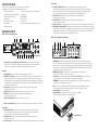
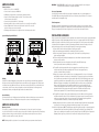
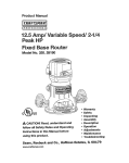
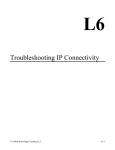
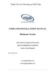
PA
D5000.5
5-CHANNEL
AM P L I F I E R
TOOLS OF THE TRADE
Listed next are the majority of the tools required to perform an installation.
Having the proper tools will make the installation that much easier.
• Solderless, crimp-on connectors and a crimping tool
• Phillips head screwdriver
• Electric drill and 3/16" and 1/8" drill bits • Safety glasses
• DMM or VOM
• Permanent ink marker or pencil
• Safety glasses
• Nylon tie straps
• Wire crimper
• Wire strippers and cutters
• Electrical tape
• Grommets for passing wires through metal car walls
• Amplifier Power Wire
End Panel Layouts
PA D5000.5 Line Level Inputs/Controls
4
5
6
INT
1
LEVEL
LPF
FULL
FULL
HPF
FRONT
HPF
FULL BPF
40Hz 4000Hz 6V 200mV
HPF
LEVEL
7
8
1
8
SUB
REMOTE LEVEL CONTROL
FL
INPUT
40Hz 220Hz
40Hz 4000Hz 6V 200mV
LEVEL
CHANNEL HPF
MODE
SUB 2
80Hz 4000Hz 40Hz 400Hz 6V 200mV
LPF
HPF
LEVEL 4CH
9
CHANNEL
MODE
80Hz 4000Hz 40Hz 400Hz 6V 200mV
LPF
HPF
LEVEL 4CH
ST
FR
RR
10
FR
7
8
9b
RL
RR
FL
FR
SUB
RL
RR
FL
FR
FR
REM
12V
REM
40A
12V
40A
SUB
RL
RR
FL
FR
RR
11
12
13
14
15
16
1.GND (Ground)—Connect this terminal directly to the metal chassis of the vehicle, using the shortest
wire necessary to make this connection. Always use wire of the same gauge or larger than the +12V power
wire. The chassis connection point should be scraped free of paint and dirt. Use only quality crimped and/or
soldered connectors at both ends of this wire. DO NOT connect this terminal directly to the vehicle battery
ground terminal or any other factory ground points.
2.REM (Remote Turn On)—This terminal turns on the amplifier when +12V is applied to it.
Connect it to the remote turn on lead of the head unit.
3
4 to the positive terminal
5
3. +12V Power—Connect this terminal through a1FUSE 2or CIRCUIT
BREAKER
of the vehicle battery or the positive terminal of an isolated audio system battery.
1
2Always3 protect this4power wire by installing 5a fuse or circuit breaker of the appropriate
WARNING:
RL
FL
RR
FR
size within 12" of the battery terminal connection.
4.Fuse—These fuses (40A x 2) protect the amplifier
against
internal
RL
FL
RR
FRelectrical damage and are meant
to protect only the amplifier. All other power connections should be fused at the power source.
PA
D4000.4
REM
12V
5. Speaker Output—Connect the speakers here.GND
40A
35A
RL
FL
RR
FR
6. Terminal Adaptor—The adaptor enables the use of cable up to 0000AWG
GND
REM
12V
for the ground and +12V connections (see illustration below).
40A
35A
RL
FL
RR
FR
10b
8. Line Level Front/Rear Inputs—Accepts line level input from the front and rear channels of a head unit.
Rear Controls
9.Rear Full, HPF Switch—Selects between no filtering or a high pass filter. The FULL setting
does not attenuate any frequencies and is for full-range speaker systems. The HPF attenuates
low frequencies and is used with mid-range speakers and tweeters.
10.Rear HPF Control—Adjusts2the high3apass 3b
filter frequency
4a
4bto attenuate frequencies
5
6 below7
the setting on the control.
3b Level
4a Control—Adjusts
4b
5the gain 6of the rear
7 channels to match the output voltage from your head unit.
3a
11.Rear
6.Terminal Adaptor
1
1
2
3
4
2
3
5
4
5
FRONT
6
SUB
FRONT
2
5b
FL
RR
40A
GND
40A
ST
RL
GND
Subwoofer
2. Sub 1/Sub2 Inputs—Line level inputs for subwoofer signal from head unit
3. SUB/INT Source Switch—Set
to the SUB position if you are
head unit’s
2
3the switch
4a 5a
9aconnecting
10a 11your 12
subwoofer output to the SUB 1 or SUB 2 inputs. Set the switch to the INT position if you are sending
(FL, FR,12
RL, RR) and not connecting anything to the SUB inputs.
3 4a a full
5a range signal to the full range
9a inputs
10a 11
In the INT position, the amplifier will filter the bass frequencies from the full range signal and send them
X-OVER
X-OVER
to the subwoofer amplifier channel.
FREQ x 1
FREQ x 1
L
L
4. Level
channel
FREQ amplifier
x 10
FREQ x 10 to match the output
X-OVER of the subwoofer
X-OVER Control—Adjusts the gain
1
LEVEL
HPF
LPF
LPF
HPF
LEVEL
FULL
FULL
voltage FREQ
from
unit.
x 1 your head FREQ
x1
HPFL
ST
HPF
BPF
4CH
BPF
R
FREQ x 10
FREQ x 10 R
5.
SUB
Sonic
Filter—Attenuates
the
frequencies
below
the
settings
on
the
control.
PA D4000.4
LEVEL
HPF
LPF
LPF
FULL
FULL
6V 200mV HPF
20Hz 400HzLEVEL
50Hz 500Hz
50Hz 500Hz 20Hz 400Hz 6V 200mV
CHANNEL
HPF
ST
HPF
BPF
4CH
BPF
REAR
MODE
frequency toR attenuate
frequencies FRONT
6. LPF Control—Adjusts the low pass filter
6V 200mV
20Hz 400Hzabove
50Hz 500Hz the setting on the control.
50Hz 500Hz 20Hz 400Hz 6V 200mV
CHANNEL
FRONT
REAR
MODE
7.Remote Level Control Jack—Connects
4b remote
5b bass
6 level7 control.
8
9b 10b
4b
5
PA D5000.5
the amplifier is on and operating normally; Protection will illuminate if the amplifier shuts down
due to short circuit, DC offset, or overheating detected by onboard protection circuitry.
R
4
PA D5000.5
40Hz 220Hz
of amplifier):
9 1.
10 Status
11 LEDs
12 (on13top 14
15 16 Power and Protection—Power will illuminate to indicate
L
3
SUB
FRONT
HPF
FULL BPF
HPF
2
RL
LPF
INPUT
FL
RL
6V 200mV 20Hz 38Hz
REAR
SUB 1
SOURCE
38Hz
LEVEL
SUB
SONIC
INT
SUB
6
SOURCE
REMOTE LEVEL CONTROL
SUB
SUB
SONIC
6V 200mV 20Hz
REAR
5
7
INPUT
SUB
4
REAR
3
3
REAR
2
Front Controls
12. Front FULL, HPF, BPF Switch—Selects full range, high pass filter, or band-pass filter. The
FULL setting does not attenuate any frequencies and is for full range speaker systems. The HPF setting
attenuates low frequencies and is used with mid-range speakers and tweeters. The BPF setting allows
you to use both the high pass filter and low pass filter, and is used with mid-range drivers.
13. Front LPF Control—Adjusts the low pass filter frequency to attenuate frequencies
above the setting on the control.
14. Front HPF Control—Adjusts the high pass filter frequency to attenuate frequencies
below the setting on the control.
15. Front Level Control— Adjusts the gain of the front channels to match the output voltage from your head unit.
16. Channel Mode Switch (4CH/ST)—Set the switch to 4CH if you are using four channel outputs from your head
unit to the FL, FR, RL, RR inputs on the amplifier. Set the switch to ST (stereo) mode if you are using two channel
outputs from your head unit. In the ST position, the amplifier will take the signal input to the FL and FR inputs
and send the same signals also to the RL and RR amplifier channels.
1
2
3
4
5
PA D5000.5 Power Inputs/Speaker Outputs
Amplifier Wiring
4Ω min/bridged
Power Connections
• PA D5000.5 Fuse Size: 2 x 40 AMP ATC
• Power connections accept up to 4 AWG wire.
4Ω min/bridged
• 4 AWG power and ground wire recommended for optimal performance.
• Connect +12V to the battery through fuse holder. This connection provides
+12V main power to the amplifier.
• Power wire must be fused within 12" of the battery.
• Ground the amplifier using a good chassis ground as close as possible to the amplifier.
• Connect REM terminal to remote turn-on lead from the head unit. This connection
provides +12V power to turn-on the amplifier.
• Add extra ground wire between the negative terminal of the battery and the chassis.
5000.5
RL
RR
FL
SUB
RL
RR
FL
FR
GND
1Ω min
2Ω min
REM
2Ω min
RL
RR
FL
FR
SUB
RL
RR
FL
FR
12V
40A
FR
SUB
40A
1Ω min
4Ω min
4Ω min
2Ω min
Passenger Compartment
If you are going to mount the amplifier in the passenger compartment, make sure you have adequate room
for ventilation. When mounting your amplifier under a seat or similar area, keep a minimum of 1" of clearance
around the amplifier for adequate cooling.
Trunk Compartment
Mounting your amplifier in the trunk provides excellent performance as long as you do not restrict the airflow
around the heatsink of the amplifier. For optimal results, mount the amplifier with as much clearance as possible.
This type of mounting will yield the best cooling due to the convection effect of the amplifier chassis.
INSTALLATION GUIDELINES
Speaker Wiring Diagram PA D5000.5
SUB
WARNING! Do not mount any amplifier in the engine compartment. Amplifiers are not designed
to endure the harsh environment of an engine compartment.
2Ω min
Bridging
The amplifier is capable of bridging two full range channels into a single full range channel with higher output power.
For instance, the front channels (FL and FR) when wired as shown will increase the output power from 70W per channel
to 200W per channel (for a 4 Ohm load). The same is true for the rear channels (RL and RR). You can do it with the front
or rear channels, or both. The most common configurations are shown in the figure above: four full range channels
and a subwoofer channel, or two bridged full range channels and a subwoofer channel.
Internal Bridging
Terminals that can be used in bridging mode are identified by the black and outlined boxes next to each terminal.
The two black boxes and the two outlined boxes work together to create an internally bridged hookup.
Amplifier Installation
Mounting Locations
The location of your amplifier will depend on several important issues. Due to the low profile and compact
size of the Polk Audio PA D Series amplifier, there are many possible installation locations that will yield satisfactory
amplifier performance. Always mount the amplifier in a place that protects the amplifier from the elements.
In addition, mount the amplifier on a stable, flat surface.
Power for systems with a single amplifier can be supplied by most automotive electrical systems. Systems with multiple
amplifiers may require a higher capacity battery, alternator or the use of a storage capacitor. Polk Audio PA D Series
amplifiers do generate a certain amount of heat as part of normal operation. Be sure the area around the amplifier
is unobstructed to allow adequate air circulation. Remember, beach blankets, last week’s laundry, school books
and homework papers placed on top of the amplifier impede air flow and may cause damage.
1.
Please read this owner’s manual carefully before installing your amplifier.
2.
Disconnect the battery ground terminal prior to making any electrical connections.
Check for any hazards or obstructions such as gas tanks, fuel or brake lines, and wiring harnesses
3.
before mounting the amplifier.
4.
Pick a mounting location that will provide adequate access and ventilation and protect the amplifier
from heat, moisture, and dirt.
5.
Avoid sharp metal areas when routing cables to the amplifier, and run RCA cables away
from the power cables and other potentially noisy car harnesses.
6. The amplifier should be grounded with a short, heavy gauge wire connected directly to the car
at a bare metal surface, preferably scraped body metal. Do not use factory ground locations,
seat bolts, or brackets that are spot welded.
7. Always fuse your power connection within 12 inches of the battery terminal. Use a fuse or circuit breaker
rated slightly more than the on-board fuse(s) of the amplifier(s). The gauge of power wire used should take
into account the total current draw of the system, and the length of wire used. IASCA and other auto sound
competition organizations have charts available for this; you can also find a chart in the MECP study guide.
Minimum wire gauge recommendations for the individual amplifiers are listed on the specification page.
Always use the same gauge wire for the amplifier ground that you use for the power wire. Be sure
to examine the battery ground cable of the vehicle, and if necessary, upgrade it by adding an additional
ground wire that is the same gauge as the amplifier’s power wire. Remember, the amplifier can only
deliver its rated output when it is not current limited by the power and ground supply wires.
8.
This amplifier is designed to drive a speaker load that measures from 2 to 8 Ohms for full range channels
and 1 Ohm for subwoofer channel. Keep in mind that heat is the long-term enemy of automotive electronics
and the lower your speaker load, the more heat is generated. For low-impedance speaker applications
or restricted ventilation installations, an external cooling fan may be advisable.
9. Battery and ground connections to the vehicle should be made with crimped ring terminals of the appropriate
size (surface area is what counts;) soldering the terminals after crimping is also recommended.
10. Due to the high-frequency MOSFET switching power supply, filtering the power cable is not generally required
(remember that the amp can’t deliver full output if the power supply is restricted.) Proper grounding of the
signal source is mandatory for the amplifier to reach its performance peak. If the RCA inputs are not grounded
adequately via the signal source, electrical noise from the vehicle may be picked up in the system.
NOTE: Mounting amplifiers upside down is not recommended and may cause premature thermal shutdown.
Step By Step Installation
1. Determine the location for the amplifier. Refer to the Mounting Locations section of this guide.
2. Decide on the system configuration for your amplifier. For system suggestions, refer to the Speaker
Wiring Diagrams section of this guide.
3. Run all the wires from the amplifier location to the speakers, source unit, and battery. Do not connect
the battery at this time. Be sure to run Line levels and power and speaker wires away from factory
electrical wires and system as they pose a great potential for induced system noise.
4. Pre-drill amplifier mounting holes. Be sure to “think before you drill.“ Gas tanks, fuel lines, and other
obstructions have a nasty way of hiding themselves. For best results use a marking pen to mark the
mounting holes and pre-drill these holes with a standard 1/8" drill bit.
5. Mount the amplifier. Make sure the amplifier is mounted on a flat surface. If this is not possible,
do not over tighten the screws so that the chassis of the amplifier is twisted or bent.
6.
Turn the vehicle’s key switch to the off position.
7.
Disconnect the vehicle’s battery ground terminal.
8.
Connect power wires to the amplifier (ground first, then +12V and REM).
9.
Connect the line level and speaker wires to the amplifier. Check the quality of your speakers
and signal connections. This will determine the ultimate performance of your Polk Audio
PA D Series amplifier. Refer to the Line Level Inputs/Controls and Speaker Wiring Diagrams
sections of this guide for correct wiring instructions.
10.Reconnect the ground terminal to the battery after power, speaker, and line level connections are completed.
11. Set crossovers. Refer to the Line Level Inputs/Controls section of this manual for detailed instructions.
12. Once satisfied that all connections and settings are correct, install the fuse located near the vehicle’s battery
and proceed to the Testing the System section of this manual.
WARNING! Never exceed the recommended fuse size of this amplifier. Failure to do so will result
in the voiding of your warranty and possible damage to the amplifier.
SET UP AND TROUBLESHOOTING
Testing the System
After you have completed the installation, you need to test the system. This will help ensure years of trouble-free
operation. Please refer to the listed steps below when testing the sound of your Polk Audio PA D Series amplifier.
1.
Check all the wiring connections to be sure they are correct and secure.
2.
Turn the signal source volume control all the way down. Set any tone controls
to their flat or defeated positions. This includes the loudness control.
3. Turn the level controls of the amplifier to their minimum positions.
4.
Turn the head unit on. Check to see if the power LED located on the connection side of the amplifier
is on. If not, please refer to the Power Inputs/Speaker Outputs and the Troubleshooting Tips sections
of this manual for instructions.
5.
If using an aftermarket head unit, turn the level controls of the amplifier about one quarter of a turn
counterclockwise. Slowly increase the volume level of the head unit so that you can hear the output
of the system. If no sound is heard or if the output is distorted, turn the system off immediately. Refer
to the Power Inputs/Speaker Outputs and the Troubleshooting Tips sections of this manual to solve
your installation problems.
6.
Check to make sure the output for each channel is correct. If the active crossovers are used, check
to make sure that each output is correct from the amplifier. When using active crossovers on midrange
and tweeters, do not use crossover frequencies lower than recommended. If the system is not configured
properly, refer to the Line Level Inputs/Controls section of this manual and take corrective action.
7.
If the output is clear and undistorted, continue to the Adjusting the Sound of the System section of this manual.
Adjusting the Sound of the System
Once you have checked the system’s operation, adjust the sound of the system. Adjusting the sound
of the system is accomplished by setting the level controls and adjusting the internal crossovers
1.
Turn the signal source volume control all the way down. Set any tone controls
to their flat or defeated positions. This includes the loudness control.
2.
Turn the level controls of the amplifier to their minimum positions.
3.
Choose music with high dynamic content that you like, with which
you are familiar, and will be used most often in the system.
4.
Turn the source unit’s volume control up to its highest undistorted output level. If you lack
test equipment, this point occurs between 3/4 to full volume depending on the quality of your
head unit. Listen for any audible distortion. If any distortion is audible, reduce the volume
of the head unit until you have an undistorted output. Leave the volume control at this
position during your system tuning.
5.
While listening to your chosen dynamic music, turn up the level control corresponding
to the midrange output until you hear slight distortion and turn the level control back slightly
for an undistorted output. Depending on your system, the midrange and tweeter output may
be on the same output channels.
6.
Turn up the level control corresponding to the tweeter output until you hear slight distortion
and turn back the level control slightly for an undistorted output. Depending on your system
the midrange and tweeter output may be on the same output channels.
Fine-tune the output level between midrange and tweeters. Refer to the Line Level
7.
Inputs/Controls section of this manual for detailed instructions.
8.
Repeat Steps 5-7 for the rear speakers. If you do not have rear speakers continue to Step 10.
9.
Set levels between the front and rear midrange and tweeters for optimum front/rear balance.
10.Turn up the level control corresponding to the woofer output until you hear slight distortion
and turn back the level control slightly for an undistorted output.
11.Fine-tune the output level between satellite speakers and the woofers. Refer to the Line Level
Inputs/Controls section of this manual for controls. Adjust the level to the bass output of the
woofer to match the sonic requirements of the system.
12.Enjoy your awesome Polk Audio PA D Series amplifier.
Troubleshooting Tips
Symptom
Probable Cause
Action To Take
Low or no remote turn-on.
Check remote turn-on at amplifier and repair as needed.
Fuse blown.
Check power wire’s integrity and check for
speaker shorts. Fix as needed and replace fuse.
Power wires not connected.
Check power wire and ground connections
and repair or replace as needed.
Audio input not connected.
Check line level connections and repair
or replace as needed.
Speaker wires not connected.
Check speaker wires and repair or replace as needed.
Speakers are blown.
Check system with known working speaker
and repair or replace speakers as needed.
No output
Audio cycles on and off
Thermal protection engages when
amplifier heat sink temperature
exceeds 85° C (185° F).
Make sure there is proper ventilation for
amplifier and improve ventilation as needed.
Troubleshooting Tips
Symptom
Specifications
Probable Cause
Action To Take
Amplifier
PA D5000.5
Amplifier
PA D5000.5
Loose or poor audio input.
Check line level connections and repair
or replace as needed.
Type
Bridgeable
Class D MOSFET
Filter Switch (Rear)
2-position (Full, HPF)
Loose power connections.
Check power wires and ground connections
and repair or replace as needed.
5 channel
High Pass Filter
Frequency Range (Rear)
40Hz - 4000Hz
Channels
RMS Continuous Power
@ 4 Ohms
70 W x 4; 200 W x 1
Rear Gain Control
200mV - 6V
Amplifier level sensitivity set
too high exceeding maximum
capability of amplifier.
Readjust gain. Refer to the Adjusting the Sound
of the System section of this manual.
Line Level Inputs (y/n)
Yes
RMS Continuous Power
@ 2 Ohms
100 W x 4; 400 W x 1
Line Level Outputs (y/n)
No
Impedance load to amplifier too low.
Check speaker impedance load, if below (2 Ohm,
4 Ohm bridged; 1 Ohm sub) rewire the speakers
to achieve higher impedance.
RMS Continuous Power
Bridged @ 4 Ohms
200 W x 2
RMS Continuous Power
1 Ohm (Sub)
500 W x 1
Distortion at Rated Power
Distorted output
Shorted speaker wires.
Check speaker wires and repair or replace as needed.
Speaker not connected
to amplifier properly.
Check speaker wires and repair or replace as needed.
Internal crossover not
set properly for speakers.
Readjust crossovers. Refer to the Line Level
Inputs/Controls section of this manual.
Speakers are blown.
Check system with known working speakers
and fix or replace as needed.
Poor bass response
Supply Voltage
10V - 16V
(2) 40 Amp ATC
<0.1%
Power Connections
4 AWG
Remote Gain Control Included
Yes (sub only)
Ground Connections
4 AWG
Minimum Impedance Bridged
4 Ohms
Speaker Connections
12 AWG
Minimum Impedance
Not Bridged
2 Ohms
Minimum Impedance
Subwoofer Channel
1 Ohm
Signal-to-noise Ratio
105dB
Frequency Response
20Hz-20kHz
12dB/octave
Check speaker polarity and fix as needed.
Crossover set incorrectly.
Reset crossovers. Refer to the Line Level Inputs/Controls
section of this manual.
Crossover Filter Slope
(dB/octave)
Impedance load at amplifier is too low.
Check speaker impedance load, if below (2 Ohm,
4 Ohm bridged; 1 Ohm sub) rewire the speakers
to achieve higher impedance.
Front Gain Control
200mV - 6V
Filter Switch (Front)
3-position
(BPF, Full, HPF)
High Pass Filter
Frequency Range (Front)
40Hz - 400Hz
Low Pass Filter
Frequency Range (Front)
80Hz - 4kHz
Short in power wire or incorrect wiring.
Check power wires and ground connections
and repair or replace as needed.
Fuse used is smaller than recommended.
Replace with proper fuse size.
Actual current exceeds fuse rating.
Check speaker impedance load, if below (2 Ohm,
4 Ohm bridged; 1 Ohm sub) rewire the speakers
to achieve higher impedance.
Yes
Yes
Fusing & Power/Type
Speakers wired with wrong polarity
causing cancellation at low frequencies.
Battery fuse blowing
LED Power Indicator
LED Protection Indicator
Height
1 13/16" (46 mm)
Depth
6 3/4" (171.5 mm)
Width
13 5/16" (338.1 mm)
Width w/ Terminal Adaptor
14 1/16" (357.9 mm)
Weight
6.75 lbs (3.06 kg)
Amplifier fuse blowing
Fuse used is smaller than recommended.
Replace with proper fuse size.
Impedance load at amplifier is too low.
Check speaker impedance load, if below (2 Ohm,
4 Ohm bridged; 1 Ohm sub) rewire the speakers
to achieve higher impedance.
Speaker is blown with shorted outputs.
Check system with known working speakers
and fix or replace as needed.
Actual current exceeds fuse rating.
Check speaker impedance load, if below (2 Ohm,
4 Ohm bridged; 1 Ohm sub) rewire the speakers
to achieve higher impedance.
POLK AUDIO
CAR AMPLIFIERS