1
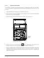
Operator’s Manual
Corporate Headquarters
4501 Parkway Commerce Blvd.
Orlando, Fl 32808
Phone: 407-578-8007
Fax: 407-578-8377
Asia-Pacific
19 Loyang Way
#01-01 CILC Building
Singapore 508724
Phone: +65 542-2611
Fax: +65 542-3611
Datamax International
Herbert House
12 Elizabeth Way, Pinnacles
Harlow, Essex CM19 5FE UK
Phone: +44 1279 772200
Fax: +44 1279 424448
Copyright Information:
CG Times (based upon Times New Roman) and CG Triumvirate are trademarks of the AGFA Monotype
Corporation.
Windows and Windows NT are trademarks of the Microsoft Corporation.
NetWare and Novell are registered trademarks of Novell, Inc.
Ethernet is a registered trademark of Xerox Corporation.
All other brand and product names are trademarks, service marks, registered trademarks, or registered
service marks of their respective companies.
Firmware (Software) Agreement:
The enclosed Firmware (Software) resident in the Printer is owned by Licensor or its suppliers and is
licensed for used only on a single printer in the user’s Trade or Business. The User agrees not to, and
not to authorize or permit any other person or party to duplicate, or copy the Firmware or the
information contained in the non-volatile or programmable memory. The firmware (Software) is
protected by applicable copyright laws and Licensor retains all rights not expressly granted. In no event
will Licensor or its suppliers be liable for any damages or loss, including direct, incidental, economic,
special, or consequential damages arising out of the use or inability to use the Firmware (Software).
Information in this document is subject to change without notice and does not represent a commitment on
the part of Datamax Barcode Products Corporation. No part of this manual may be reproduced or
transmitted in any form or by any means, for any purpose other than the purchaser's personal use,
without the expressed written permission of Datamax Corporation.
All rights reserved. Printed in the United States of America.
© Copyright 2005 by Datamax Corporation
Part Number: 88-2305-01
Revision G
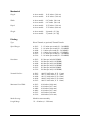
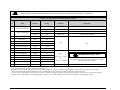
Agency Compliance and Approvals:
C
US
UL60950 Information Technology Equipment
C22.2 No. 950-M93
Listed
EN60950
For 230 Volt Operation (Europe): Use a cord set, marked “HAR,” consisting of a
min H05VV-F cord which has a minimum 0.75 square mm diameter conductors,
provided with an IEC 320 receptacle and a male plug for the country of
installation rated 6A, 250V
Für 230 Volt (Europa): Benützen Sie ein Kabel, das mit “HAR” markiert ist,
bestehend mindestens aus einem H05VV-F Kabel, das mindestens 0,75
Quadratmillimeter Drahtdurchmesser hat; sowie eine IEC320 Steckdose und
einen für das Land geeigneten Stecker, 6A, 250 Volt.
As an Energy Star Partner, the manufacturer has determined that this product meets the
Energy Star guidelines for energy efficiency.
The manufacturer declares under sole responsibility that this product conforms to the
following standards or other normative documents:
EMC:
EN 55022 (1993) Class B
EN 50024 (1998)
Safety: This product complies with the requirements of
EN 60950/All: 1997
FCC: This device complies with FCC CFR 47 Part 15 Class A.
Note: This equipment has been tested and found to comply with the limits for a Class A
digital device, pursuant to Part 15 of the FCC Rules. These limits are designed to
provide reasonable protection against harmful interference when the equipment is
operated in a commercial environment. This equipment generates, uses, and can
radiate radio frequency energy, and if not installed and used in accordance with the
instructions in this manual, it may cause harmful interference to radio
communications. Operation of this equipment in a residential area is likely to cause
harmful interference in which case the user will be required to correct the
interference at his own expense.
Important Safety Instructions:
Throughout the literature accompanying this unit, the exclamation point within an
equilateral triangle is intended to alert the user to the presence of important
operating and maintenance instructions.
This unit has been carefully designed to provide years of safe, reliable performance. However, as with all
electrical equipment, there are some basic precautions that you should follow to avoid personal injury or
damage to the printer:
Before using the print engine, carefully read all the installation and operating instructions.
Moving parts are present during operation – keep body parts, loose clothing, etc. away from the
mechanism.
Observe all warning instruction labels on the print engine.
Mount the print engine securely in the applicator system.
Do not place the print engine on or near a heat source.
To protect from overheating, make sure no openings on the print engine are blocked.
Never insert anything into the ventilation slots and openings of the print engine.
Do not use the print engine near water or spill liquid into it.
Ensure that the AC power source complies with the ratings listed for the print engine.
Do not place the AC power cord where it can be stepped on. If the AC power cord becomes damaged,
replace it immediately.
Consult only qualified, trained personnel to perform service on this print engine. There are no userserviceable parts are inside; do not remove the cover.
Contents
Overview
1.1 About the Printer ................................................................................................. 1
1.1.1 Standard Features .................................................................................... 2
1.1.2 Optional Features...................................................................................... 3
1.2 Installing Printer Options...................................................................................... 6
1.3 Index to Parts and Controls.................................................................................. 7
1.3.1 Right Hand Models.................................................................................... 8
1.3.2 Left Hand Models...................................................................................... 9
Getting Started
2.1 Unpacking the Printer ........................................................................................ 11
2.1.1 Contents ................................................................................................. 12
2.1.2 Additional Printing Requirements............................................................. 12
2.2 Selecting Media and Ribbon .............................................................................. 12
2.3 Adjusting Print Quality ....................................................................................... 14
Printer Setup
3.1 Environmental Requirements............................................................................. 15
3.2 Mounting the Printer .......................................................................................... 15
3.2.1 Peel Point Dimension .............................................................................. 19
3.3 Connecting the Printer ....................................................................................... 19
i
3.3.1 Communications Connections ................................................................. 19
3.3.1.1 USB Connections...................................................................... 20
3.3.1.2 Parallel Port Connections .......................................................... 20
3.3.1.3 Serial Port Connections............................................................. 21
3.3.1.3.1 RS-422/485 Communications...................................... 22
3.3.1.4 DMXNet Connections................................................................ 24
3.3.1.5 DMXrfNet Connections.............................................................. 25
3.3.2 Applicator Connections............................................................................ 26
3.3.3 Power Connections ................................................................................. 27
3.4 Loading Media................................................................................................... 29
3.5 Adjusting the Media Sensor ............................................................................... 34
3.6 Loading Ribbon ................................................................................................. 35
3.6.1 Removing Ribbon.................................................................................... 35
The User Interface
4.1 User Interface Functions.................................................................................... 39
4.1.1 Ready Mode ........................................................................................... 40
4.1.2 Menu Mode............................................................................................. 41
4.1.2.1 Save Changes Window ............................................................. 42
4.1.3 Test Mode............................................................................................... 43
4.1.3.1 Test Mode System Window ....................................................... 44
4.1.4 MCL Mode .............................................................................................. 45
4.2 The Menu System ............................................................................................. 46
4.2.1 Entrance and Exit Prompts ...................................................................... 47
ii
4.2.2 Media Settings ........................................................................................ 48
4.2.3 Print Control............................................................................................ 49
4.2.4 Printer Options........................................................................................ 50
4.2.5 System Settings ...................................................................................... 55
4.2.6 Communications ..................................................................................... 62
4.2.7 Diagnostics ............................................................................................. 66
4.2.8 MCL Options........................................................................................... 67
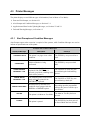
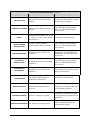
4.3 Printer Messages .............................................................................................. 68
4.3.1 Alert Prompts and Condition Messages ................................................... 68
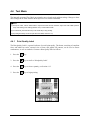
4.4 Test Mode ......................................................................................................... 70
4.4.1 Print Quality Label................................................................................... 70
4.4.2 Configuration Label ................................................................................. 71
4.4.3 Quick Ribbon Test Label ......................................................................... 72
4.4.4 Validation Label ...................................................................................... 73
4.4.5 Print Last Label ....................................................................................... 73
4.4.6 User Defined Label.................................................................................. 74
4.4.7 Demo...................................................................................................... 74
Adjustments and Maintenance
5.1 Media Sensor Calibration................................................................................... 75
5.1.1 Quick Calibration..................................................................................... 75
5.1.2 Standard Calibration................................................................................ 76
5.1.3 Advanced Entry Calibration ..................................................................... 79
5.2 Printhead Adjustments....................................................................................... 85
iii
5.2.1 Leveling Cam Adjustment........................................................................ 85
5.2.2 Burn Line Adjustment .............................................................................. 87
5.3 Printhead Replacement ..................................................................................... 89
5.4 Maintenance Schedule ...................................................................................... 93
5.4.1 Cleaning the Printhead ............................................................................ 94
5.4.1.1 Cotton Swab Procedure ............................................................ 95
5.4.1.2 Cleaning Card Procedure .......................................................... 96
5.4.1.3 Cleaning Film Procedure ........................................................... 97
5.4.2 Cleaning the Rollers................................................................................ 99
5.4.3 Cleaning the Peel Assembly.................................................................. 100
5.4.4 Cleaning the Media Sensor, Media Path, and Peel Bar........................... 101
5.4.5 Cleaning Exterior Surfaces .................................................................... 102
5.5 Application Program Updates........................................................................... 102
5.5.1 Updating the Application Version ........................................................... 103
5.5.2 Possible Problems during an Update ..................................................... 104
5.6 Boot Loader Program Updates......................................................................... 105
Troubleshooting
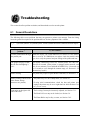
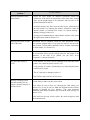
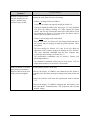
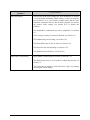
6.1 General Resolutions ........................................................................................ 107
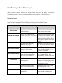
6.2 Warning and Fault Messages........................................................................... 111
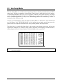
6.3 Hex Dump Mode ............................................................................................. 116
6.4 Resetting the Printer........................................................................................ 117
6.4.1 Soft Reset............................................................................................. 117
6.4.2 Level One Reset ................................................................................... 117
iv
6.4.3 Level Two Reset ................................................................................... 117
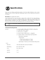
Specifications .................................................................................................... 119
Appendix A
ASCII Control Code Chart........................................................................................ 125
Appendix B
Available Fonts and Bar Codes................................................................................ 127
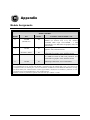
Appendix C
Module Assignments ............................................................................................... 135
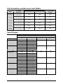
Print Resolutions and Maximum Label Widths.......................................................... 136
Speed Ranges ........................................................................................................ 136
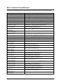
Menu Constraint Cross-Reference ........................................................................... 137
PE Peel Bar Location .............................................................................................. 139
PE to A-Class GPIO Adapter Cable ......................................................................... 139
Appendix D
Applicator Interface Card Overview .......................................................................... 141
GPIO Interface Setup .............................................................................................. 144
Applicator Timing Signals ........................................................................................ 147
v
Appendix E
Multi-Language Menu System ................................................................................. 151
Appendix F
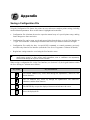
Saving a Configuration File...................................................................................... 157
Appendix G
Ribbon Saver Overview ........................................................................................... 159
Warranty Information....................................................................................... 161
Glossary .............................................................................................................. 163
vi
Overview
1.1
About the Printer
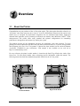
Congratulations on your purchase of the A-Class print engine. This print engine (hereafter referred to as
“the printer” and, when necessary, the A-4xxx or A-6xxx to differentiate between the four and six inch
model sizes) is designed for professional integration into an automated high-volume, high-speed
industrial label applicator system. Featuring an advanced user interface and a Motorola Coldfire® 32-Bit
microprocessor, this printer offers many standard and optional configurations for outstanding
performance, management, and connectivity within your system.
This manual provides all the information necessary for installation, setup and operation. To begin
printing, refer to the instructions provided with your label-creation software; or, if you are writing custom
label programs, the Class Series Programmer’s Manual has been included on the enclosed Datamax
Accessories CD-ROM for your convenience. (This manual is also available on our web site at
http://www.datamaxcorp.com).
For easy reference, the printer’s model number is located on the Serial Tag affixed to the inside of the
front cover. Use this model number when referencing specific information within this manual. The
following subsections detail the standard and optional features for the A-Class printer.
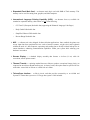
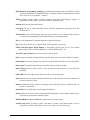
Left Hand Model
A-Class
Right Hand Model
1
1.1.1
Standard Features
This printer offers the following standard features:
Right-handed or left-handed configurations
Electronics card cage
4 MB Flash downloadable program memory
16 MB DRAM memory
Host computer accessible memory for object temporary storage
Two RS-232 serial interfaces (one of which is also RS-422/RS-485 capable)
One IEEE 1284 compliant parallel interface
One USB v1.1 interface
A programmable GPIO Port
Backlit ¼ VGA graphic display panel
EFIGS (English, French, Italian, German, and Spanish) display languages
Industry standard bar code symbologies
Time stamp at print capability with time and date battery back-up
Static brushes
Printhead resistance verification
Configurable fault-handling capability with reprint and void selections
Parse error-tolerant command language interpretation
Internal test labels for verification, validation, and configuration
Multiple setup restore capability
Paper retract control after print
Ribbon low detection and warning
Power-up, mode, and resident option hardware diagnostics
Option hardware auto-detection
Media peel bar
Media inch counters
Input line mode (ASCII text input) capability
Firmware upgrades downloadable
AGFA Scaleable Font Engine featuring dynamic font attributes
2
A-Class
1.1.2
Optional Features (available for all models, except as noted)
The printer offers the following optional features:
DMXNet – a network interface card that enables the printer to communicate over an Ethernet®
network under a variety of operating systems including NetWare, Windows 95/98/2000/ME/XP,
Windows NT™, and UNIX™. Some of the features are listed below:
−
Automatic selection of 10Base2 (Thinnet) or 100BaseT Fast Ethernet connection.
−
Integral HTTP Server to allow monitoring and management from a standard Web browser
program.
−
Peer-to-Peer (serverless) discovery and printing from Windows 95/98/ME/XP or Windows
NT/2000 workstations without a Novell file server present.
−
FTP printing to allow printing from a Web browser or other FTP client.
−
Dynamic Domain Name Service (DDNS).
−
Lightweight Directory Access Protocol (LDAP).
−
Novell “YES” certified.
−
Novell NetWare PSERVER (bindery-based and Novell Directory Services (NDS).
−
LPR/LPD over TCP/IP for UNIX platforms and Microsoft’s Windows.
−
Raw sockets support over selectable TCP/IP port with filters for selected UNIX environment.
−
IP and IPX SNMP support of MIB-2, proprietary NIC MIB and public and proprietary (private)
Printer MIB.
−
SNMP traps to alert administrators of printer errors.
−
E-mail notification of printer errors to specified addresses.
−
Universal Plug and Play (UPnP).
−
FTP download allows users to upgrade the interface’s Flash memory.
A-Class
3
DMXrfNet – a high-performance 802.11b, WiFi compatible, network interface card that enables the
printer to communicate in a wireless network environment. Some of the features are listed below:
4
−
TCP/IP (lpd or raw TCP port), Direct Mode IPX/IP, IPX/SPX, NetBEUI, and NetBIOS/IP
support
−
A PCMCIA connector for other supported 802.11b wireless devices
−
Frequency in the 2.4 GHz ISM band, with variable data rates of 11, 5.5, 2, and 1 Mbps
−
Selectable Wired Equivalent Privacy
−
Sensitivity of -91dBm at 1Mbps, -88dBm at 2Mbps, -87dBm at 5.5 Mbps, and - 84dBm at 11
Mbps; Range of 100m indoors and 300m outdoors
−
Industry standard MMCX diversity antenna connectors
−
Hot swappable 10baseT Ethernet port for wired connections
−
RS-232 compatible serial port with selectable baud rates to 230.4Kbps.
−
Datamax Web XAdmin web-browser facility including English, German, French, and Dutch
multilingual capability
−
Datamax XAdmin NetWare/VINES/TCP/IP Windows-based utility
−
Console accessible via serial port, TELNET or NetWare
−
NetWare PCONSOLE, PRINTCON, PRINTDEF, NWADMIN; automatic detection of NetWare
frame type, or frame type can be forced
−
Simple Network Management Protocol MIB I and II; IP or IPX
−
Multiple server firmware downloads via NetWare or TCP/IP (master mode tftp, slave mode
TFTP, or BOOTP)
−
On-line Help guide; Diagnostics including protocol trace capability and crash dump
−
Multiple services per port
−
lpd-Plus virtual printer capability for complex user-defined setup and reset strings configurable
on a per-service basis
−
Programmable character string conversion
−
IP security allows access restriction to the Card based on IP addresses; IP address configuration
via serial port, arp, rarp, DHCP, BOOTP, Xadmin & WP-Admin utility, JetAdmin/Web
JetAdmin, and NetWare; configurable TCP port numbers on a per-service basis
A-Class
Expanded Flash Main Card – an alternate main logic card with 8MB of Flash memory. This
memory can be used for storing fonts, graphics, and label templates.
International Language Printing Capability (ILPC) – an alternate font set, available for
standard or expanded memory, that consists of one of the following:
−
CG-Times™ (European) Scaleable font (supporting the Enhanced Language Code Pages)
−
Kanji Gothic B Scaleable font
−
Simplified Chinese GB Scaleable font
−
Korean Hangul Scaleable font
MCL – a software tool suite designed for data collection applications. Once enabled, the printer can
accept input data from peripheral devices such as barcode scanners, weigh scales, and keyboards
without the need of a host computer, requesting and sending data to locally resident lookup files or
remote databases, enhancing communication capabilities within your system while reducing your
hardware investment.
Remote Display – a detached display assembly that features a six-foot (1.8 m) cable for
convenient, remote printer control.
Thermal Transfer – a printing method that uses ribbon to produce exceptional image clarity (as
compared to most direct thermal media types). At time of order, this option must be specified for use
with either ‘coated side in’ ribbon or ‘coated side out’ ribbon.
Twinax/Coax Interface – a slide-in circuit card that provides connectivity to an AS/400 and
System/3X Twinax host system or a 3270-type host system. Cable included.
A-Class
5
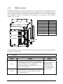
1.2
Installing Printer Options
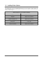
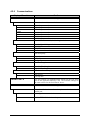
The following table lists the recommended qualification level for the installer of printer options. For
detailed information concerning a specific option or the required level of expertise, contact your dealer or
Datamax Technical Support.
Required Experience Level for Options Installation
6
Option
Installer
DMXNet
DMX Certified Technician
DMXrfNet
MCL
DMX Certified Technician
DMX Certified Technician
Expanded Flash Main Card
Remote Display
DMX Certified Technician
DMX Certified Technician
Ribbon Saver
Thermal Transfer
Factory Only
DMX Certified Technician
Twinax/Coax Interface
DMX Certified Technician
A-Class
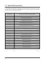
1.3
Index to Parts and Controls
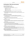
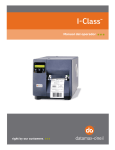
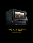
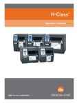
User-assessable parts and controls are highlighted in the table below. On the following pages, drawings
for right and left hand models detail the location of these items. Some components are optional and,
therefore, may not be included with your printer.
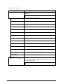
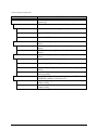
Item Number
Item Name and Related Section in this Manual
1
User Interface, Section 4
2
3
4
Power On/Off Switch, Section 3.3
Access Cover, Section 2.1
Power Receptacle, Section 3.3.4
5
6
7
8
9
GPIO Port, Section 3.3.2
Serial Communications Port, Section 3.3.1
Universal Serial Bus Communications Port, Section 3.3.1
Parallel Communications Port, Section 3.3.1
Auxiliary (Serial B) Port, Section 3.3.1
10
11
12
13
14
Ribbon Take-Up Hub, Section 3.6*
Ribbon Supply Hub, Section 3.6*
Upper Media Post, Section 3.4
Lower Media Post, Section 3.4
Cover Sensor, Section 6.2
15
16
17
18
19
Upper Ribbon Idler, Section 3.6
Leveling Cam, Section 5.2.1
Printhead Assembly, Section 5.2.2
Peel Bar, Section 3.2.1
Platen Roller, Section 5.4.2
20
21
22
23
24
Head Lift Lever, Section 3.4
Media Sensor, Section 3.5
Media Sensor Adjustment Knob, Section 3.5
Media Guide, Section 3.4
Peel Assembly Release Lever, Section 3.4
25
26
Locking Post, Section 3.4
Peel Assembly, Section 3.4
*Optional feature
A-Class
7
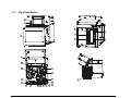
1.3.1
Right Hand Models
1
2
4
6
9
7
3
8
5
3
10
11
14
15
16
12
13
23
8
26
17
24
22 21
25
20
19
18
A-Class
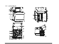
1.3.2
Left Hand Models
1
2
4
3
8
5
7
6
9
10
11
14
15
16
12
17
13
18
A-Class
19
20
25 21 22
24
26
23
9
10
A-Class
Getting Started
This section describes how to unpack printer, select printing supplies, and achieve the best print quality.
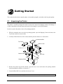
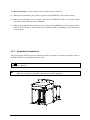
2.1
Unpacking the Printer
The printer is carefully packaged for transit. Upon arrival, inspect the shipping carton(s) for damage; if
evident, immediately report the nature and extent of the damage to your freight company.
In order to operate the printer, remove all packaging material:
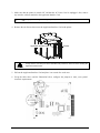
1. With the orientation arrow on the box pointing upward, open the Shipping Carton and remove the
Top Foams and the Accessories Box.
2. Carefully lift the Printer out of the carton, and then place the Printer on a solid surface.
Accessories Box
Top Foam
Bottom Foam
Printer
Bottom Foam
Top Foam
Shipping Carton
3. Remove the plastic bag from the Printer. Open the access cover and remove the packing material
from the printhead assembly; see Section 1.3.
4. Lower the Head Lift Lever and close the Access Cover.
Note: Save the carton and packaging materials in the event that future shipment is required.
A-Class
11
2.1.1
Contents
Check the contents of the package. In addition to documentation, the following items should be present:
The printer
A power cord
The Accessories CD-ROM
Any special additionally purchased items or options.
2.1.2
Additional Printing Requirements
To begin label production, the following items may also be necessary.
Media (and ribbon, if necessary); see Section 2.2.
A communications interface cable; see Section 3.3.1.
An applicator interface cable; see Appendix D.
Additional labeling software (see the Accessories CD-ROM for
Windows™ Drivers and basic labeling software).
2.2
Selecting Media and Ribbon
Printing supplies are a major consideration in determining the quality of the final product. Printing bar
codes or detailed images on inexpensive direct thermal and thermal transfer media can be difficult. Many
low-cost direct thermal stocks have raised reaction temperatures and therefore require higher heat values
or slower speeds to print a clear image. In some cases, to print detailed images at high speeds, media with
a low reaction or release temperature is required because the media will not be stretched beyond its limits.
A brief overview of the two different media categories is included below. For information regarding a
specific application always consult a qualified media specialist or a Datamax Media Representative.
Direct Thermal Media
Three important factors to consider when selecting a direct thermal stock:
•
The abrasive qualities of the material that covers the thermal reactive layer of the media.
•
The amount of heat required to burn an image into the media.
12
A-Class
•
The ability of the media’s reactive layer to control the chemical reaction that occurs as the image is
created.
Thermal Transfer Media
Three important factors to consider when selecting a thermal transfer stock:
•
The combination of the label’s top coating and the ribbon can affect image quality.
•
A backcoating layer on the ribbon can provide printhead protection and, depending upon the formula,
help reduce static build-up.
•
The use of a ribbon with a slightly greater width than that of the media can help protect the printhead.
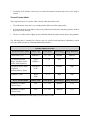
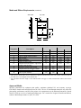
The following table is intended for reference only; for specific media application information, consult
with your media specialist or a Datamax Media Representative.
Printing Supplies Overview
Thermal Transfer Media
Ribbon Type
Print Speed*
Print Energy
Image Durability
Great Label TTL™
GPR Plus™
10 – 12**
Medium
Medium
Coated and Uncoated
Paper, Tag Stock, Some
Films, Some Synthetics
Wax
GPRPlus™
2 – 10
Low
Low
Coated and Glossy Paper,
Tag Stock,
Some Synthetics, Films
Wax/Resin
PGR+
2–8
Medium
High
Resin
SDR
4–6
High
High
Ribbon Type
Print Speed*
Print Energy
Image Durability
Datamax DTL-HSM
Thermal Paper
N/A
10 – 12**
Medium
Low
Datamax DTL-HSH
Thermal Paper
N/A
10 – 12**
Medium
Low
Synthetics, Films
Direct Thermal Media
*Speeds given in inches per second
**Highly recommended for optimum quality at print speeds above 10 IPS.
A-Class
13
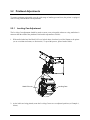
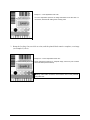
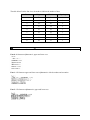
2.3
Adjusting Print Quality
Printing flexibility is provided by a comprehensive set of print controls. Of these, the amount of print heat
and the print speed will have the greatest effect.
Five settings are available to control print quality; all are accessible via the menu system:
•
The first setting is the media type. Go to MEDIA SETTINGS
and select the setting that matches the media being used.
•
The second setting is the heat value. Go to PRINT CONTROL
HEAT (see Section 4.2.3) and
increase this value to darken the image, or reduce this value to lighten the image.
•
The third setting is the speed value. Go to PRINT CONTROL
PRINT SPEED (see Section
4.2.3) and change the amount of time that the label remains under the printhead. Slower settings allow
more time and control for energy transfer, while faster settings increase throughput, but may require
higher heat settings to achieve the desired darkness.
•
The fourth setting is the contrast value. Go to PRINT CONTROL
CUSTOM ADJUSTMENTS
CONTRAST (see Section 4.2.3). This is a fine-tuning adjustment, predominately affecting the gray
(shaded) areas of the image.
•
The final setting is the darkness value. Go to PRINT CONTROL
CUSTOM ADJUSTMENTS
DARKNESS (see Section 4.2.3). This is a fine-tuning adjustment, affecting the solid areas of the
image.
MEDIA TYPE (see Section 4.2.2)
Note: Heat and Speed values received by host software commands (selectable as “Heat Setting” and “Speed
Setting” in most labeling programs) may override the printer’s menu setting; see HOST SETTINGS in
Section 4.2.6 for details.
14
A-Class
Printer Setup
This chapter explains how to mount, connect, and setup the printer.
3.1
Environmental Requirements
Before installing the printer, ensure that the ambient environmental conditions of the site fall within the
ranges listed in Section 7. In addition, do not install the printer in the following environments:
Where it will be exposed to direct sunlight or other heat source.
Where it will be exposed to liquids or excessive dust or dirt.
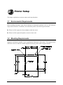
3.2
Mounting Requirements
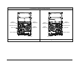
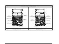
Important consideration should be given regarding the dimensions of the printer. The template below
details the cutout size and hole locations required to place the printer within a support structure:
A-Class
15
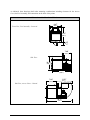
As indicated, these drawings detail other mounting considerations including clearance for the Access
Cover, the Peel Assembly, and connections to the back of the printer.
Dimensions of the Four-Inch Models
9.67”
(246mm)
Front View, Peel Assembly – Lowered:
11.81”
(300mm)
2.25”
(57mm)
7.68”
(195mm )
Side View:
10.45”
(266 mm)
15.35”
(390mm)
12.51”
7.66”
(318mm)
(195mm)
Side View, Access Cover – Raised:
20.17”
(512mm)
16
A-Class
Dimensions of the Six-Inch Models
9.67”
(246mm)
Front View, Peel Assembly – Lowered:
11.81”
(300mm)
2.25”
(57mm)
9.68”
(246mm)
Side View:
10.45”
(266mm)
17.35”
(441mm)
7.66”
(195mm)
14.51”
(369mm)
Side View, Access Cover – Raised:
22.17”
(563mm)
A-Class
17
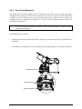
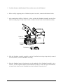
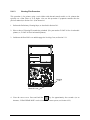
When attaching the printer to the supporting framework, use #10 screws inserted at the four pre-drilled
Mounting Holes.
Mount the printer as follows:
1. Align the printer’s Mounting Holes to the corresponding points in the supporting framework of the
applicator.
Mounting Holes
2. Hold the printer in place and insert a #10 screw in a mounting hole.
3. Start and finger-tighten the screw.
4. Start and finger-tighten the screws for the three remaining mounting holes.
5. Completely tighten all four screws.
18
A-Class
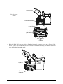
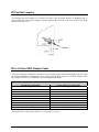
3.2.1
Peel Point Dimension
The following dimensions detail the location of the Peel Bar. (Although this example shows a right hand
model, the left hand model will have the identical dimensions.)
Peel Bar
Note: Integrators switching from the PE printer, the reference dimension for the old Peel Bar location is
included in Appendix C.
3.3
Connecting the Printer
The following procedures detail the data and electrical connections to the printer.
3.3.1
Communications Connections
The standard printer can be interfaced to a host via serial, USB, and parallel connections. The printer will
automatically establish communications through the first port that receives valid data. Once established,
the timeout period must be exceeded (ten seconds at default, see Section 4.2.6) or the printer’s power
must be cycled ‘Off and On’ to change the communication port.
Note: Depending upon the model, the location of the following communications connections can vary.
A-Class
19
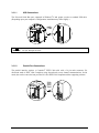
3.3.1.1
USB Connections
The Universal Serial Bus port, supported in Windows®95 and greater, requires a standard USB cable.
(Depending upon your computer’s configuration, installation may differ slightly.)
WARNING
3.3.1.2
This USB Port is a device-end only connection. Never attach a keyboard, mouse, modem, etc. to
this port. Damage can result.
Parallel Port Connections
The parallel interface requires a Centronics® IEEE 1284 cable with a 36 pin male connector. Bidirectional mode is IEEE 1284 Compliant, using forward and reverse channel communications. In this
mode, data can be sent to the host provided it is also IEEE 1284 Compliant and has supporting software.
20
A-Class
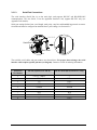
3.3.1.3
Serial Port Connections
The serial interface (Serial Port A) on the main logic card supports RS-232C and RS-422/RS-485
communications. The Aux Serial, J1 on the Applicator Interface Card, supports RS-232C only (see
Appendix D for details).
Serial port settings for baud rate, word length, word parity, stop bits, and handshaking protocol are menuselectable and must be configured to match the host’s port settings; see Section 4.2.6.
10101010
Serial Port A
Aux Serial
The available serial cables and part numbers are shown below. For proper data exchange, the serial
interface cable requires specific pin-outs (see diagram). Contact a reseller for ordering information.
Serial Port
Pin Number
RS-232 (Serial Port A and B)
RS-422 & RS-485 (Serial Port A, only)
Function
Function
1
2
3
4
5
6
7
8
9
+5V (@ .5 amps)
RX
TX
DTR
Ground
--RTS
CTS
---
--RXD +
TXD –
RXD –
Ground
--RTS
CTS
TXD +
A-Class
21
RS-232 Cables*
Part # 32-2300-01
Part # 32-2301-01
*The serial port requires a DB9 male connector (e.g., Startech C9PSM).
3.3.1.3.1
RS-422/485 Communications
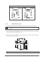
To use RS-422/485 communications, the main logic card must be reconfigured, as described below:
Always wear a wrist strap and follow standard ESD prevention measures when handling the Main
CAUTION Logic Card.
1. Turn ‘Off’ the power switch, unplug the AC Power Cord from the printer, and remove any interface
cable(s) already attached to the Main Logic Card.
2. Remove the two Screws securing the Main Logic Card to the printer. Slide the card out of the printer
and place it on a static free work area.
Main Logic Card
Screws
Note: Depending upon the model of printer, the location of the Main Logic Card can vary.
22
A-Class
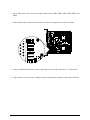
3. On the Main Logic Card, remove the jumpers placed across JMP1, JMP2, JMP3, JMP4, JMP5, and
JMP6.
4. Slide the Main Logic Card back into the printer and secure it using the screws removed earlier.
JMP 1
JMP 2
JMP 3
JMP 4
JMP 5
JMP 6
5. Connect an RS-422/485 interface cable to Serial Port A (see the table in Section 3.3.1.3 for details).
6. Plug in and turn ‘On’ the printer. Configure the port communication settings to match that of the host.
A-Class
23
3.3.1.4
DMXNet Connections
The DMXNet option has several menu-selectable modes, as detailed under ‘NIC ADAPTER’ in Section
4.2.6. For detailed installation, configuration, and operational instructions, refer to the DMXNet Resource
Manual, provided with the option. Use the following universal Ethernet 8-wire standard when configuring
your 10/100BaseT cables for the DMXNet Card. Depending on the length, the cable should be
Category/Type 3 or better.
RJ45 Pin Number
1
2
3
4
5
6
8
7
8
DMXNet Card
Ethernet
Transmit +
Transmit –
Receive +
–
–
Receive –
–
–
–
RJ45 Connector
Status Indicators
Network Cable
The Status Indicators (LEDs), viewable from the back of the printer, provide a quick operational check of
the interface, as defined below:
Note:
24
After power-up, wait until ‘DMXNET INITIALIZING’ is no longer displayed (about two minutes) before
proceeding.
Status
Indicator
Normal
Conditions
Green
Upon power-up, this LED is ‘On’ to indicate that the
card is performing self-tests, afterward the LED flashes
and may flash again as soon as the printer’s
initialization is complete. This LED may also be ‘On’
when awaiting a print job.
Amber
Generally indicates job activity. When receiving print
jobs over the network, the LED flashes; it remains
‘Off’ during inactivity.
Other
Conditions
One to seven blinks of
the Amber LED -followed by one to
twelve blinks of the
Green LED indicates a
hardware failure.
A-Class
3.3.1.5
DMXrfNet Connections
The DMXrfNet option has several menu-selectable modes, as detailed under ‘NIC ADAPTER’ in Section
4.2.6. Depending upon the method you select to configure the DMXrfNet card, you may need a hard wire
connection. In addition, a hard wire connection is necessary if you plan to use the 10 BaseT port or the
Serial Server in your application.
The drawing below illustrates the available mode-dependant connections to the DMXrfNet Card. For
detailed installation, configuration, and operational instructions, refer to the DMXrfNet Resource Manual,
provided with the option.
DMXrfNet Card
Serial Console or Serial Printer Cable
Console/Serial Server Connector
RJ45 Connector
Reset/Test Button
Status Indicators
Network Cable
Antenna
Status
Indicators
Normal
Conditions
Wireless
This red indicator initially comes ‘On’ and then cycles ‘Off’ when power is applied to
the printer. Thereafter, ‘On’ denotes that a wireless link is established.
ACT/Err
This green indicator blinks during network activity.
LNK
A-Class
This yellow indicator initially comes ‘On’ and then goes Off’ when power is applied
to the printer. Thereafter, ‘On’ denotes that a 10 BaseT Ethernet connection is
established.
25
The Reset/Test Button is a multi-function switch with the following functions:
(1) When pressed momentarily, this produces a printout of the DMXrfNet Card’s current settings.
(2) When pressed and held for five seconds, this resets the DMXrfNet Card to the factory default
parameters. (The default password is access)
(3) When pressed and held during printer power-up, this causes the DMXrfNet Card to assume Ad-Hoc
mode on WiFi Channel 11 with the Service Set Identifier (SSID) of printer. (This also restores
Console mode.)
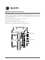
3.3.2
Applicator Connections
After setting up the GPIO Port per the instructions found in Appendix D, connect the applicator cable to
the GPIO Port (J2) on the Applicator Interface Card:
WARNING
Failure to properly configure the GPIO Port may result in damage to the printer and / or the
applicator.
Note: Integrators switching from the PE printer, an adapter cable (part number 32-2562-01) is available for the
GPIO Port connection. Pin-out details of this cable are included in Appendix C.
26
A-Class
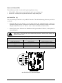
3.3.3
Power Connections
The AC power connection is made via the receptacle on the back of the printer. The printer’s power
supply is auto ranging; for the acceptable voltage ranges, see Section 7. Make electrical connections and
power-up the printer as follows:
1. Ensure that AC power to the host computer and applicator system is ‘Off’.
2. Ensure that the printer’s Power Switch is in the ‘Off’ position.
Power Switch
3. Ensure that the appropriate communications cable is connected from the host to the printer; see
Section 3.3.1.
4. If additional serial communications are needed, ensure that a serial cable is connected from the host to
the Aux Serial Port (J1) on the Applicator Interface Card; see Section 3.3.1 for details.
5. Ensure that the applicator cable is connected to the GPIO Port; see Section 3.3.2 for details.
WARNING
A-Class
Failure to properly configure the GPIO Port may result in damage to the printer and / or the
applicator.
27
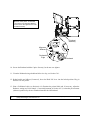
6. Connect the AC Power Cord to the printer, and then plug the AC Power Cord into a properly
grounded outlet.
7. Turn ‘On’ the host computer, the applicator system, and then the printer.
28
A-Class
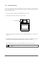
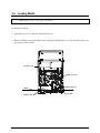
3.4
Loading Media
Note: At default settings, a Buzzer will sound when the Access Cover is raised. To disable this function see
Section 4.2.5, System Settings
Buzzer.
Load media as follows:
1. Open the Access Cover and raise the Head Lift Lever.
2. Route the Media between the Media Posts, through the Media Sensor, over the Peel Bar, and out of
the printer, as shown below.
Access Cover
Head Lift Lever
Media
Media Posts
A-Class
Media Sensor
Peel Bar
29
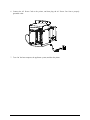
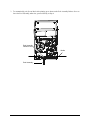
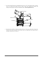
3. To automatically peel die-cut labels after printing, press down on the Peel Assembly Release Lever to
lower the Peel Assembly; otherwise, proceed directly to Step 6.
Peel Assembly
Release Lever
Media
Peel Assembly
30
A-Class
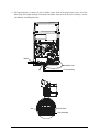
4. Pull approximately 12 inches (30 cm) of media out the front of the printer then remove all of the
labels from this length of Media Liner. Route the Media Liner down to the Peel Assembly, over the
Latch Roller, and through the Slot.
Media
Media Liner
Peel Assembly
Slot
Latch Roller
Peel Assembly
A-Class
31
5. Pull the Media Liner through the Slot in the Peel Assembly until all slack is removed. Lifting from
the center, raise the Peel Assembly until it locks into place.
Head Lift Lever
Media Guide
Peel Assembly
32
A-Class
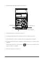
6. Position the Media Guide lightly against the side of the media.
Media Guide
Head Lift Lever
Locking Post
7. Adjust the Media Sensor over the labels (see Section 3.5).
8. If printing on thermal transfer media, load ribbon (see Section 3.6); otherwise go to Step 9.
9. Lower the Head Lift Lever until it is completely and securely engaged onto the Locking Post.
10. If loading media for the first time, or changing to a different media type or size, perform a Quick
Calibration:
With the printer powered ‘On,’ press and hold the
FEED
Key until at least two labels have been
output (see Section 5.1.1 for details).
11. Adjust the Leveling Cam (see Section 5.2.1).
A-Class
33
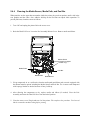
3.5
Adjusting the Media Sensor
The Media Sensor detects labels. Position the Media Sensor as follows:
1. Load media, ensuring that the media is routed through the Media Sensor, as described in Section 3.4.
2. Depending on the type of media being used, rotate the Media Sensor Adjustment Knob until the Eye
Mark on the Media Sensor is positioned according to the table below.
Note: The printer defaults to the ‘Gap’ Sensor Type for use with die-cut and notched media. If using a different
media, change the Sensor Type. Use your software program, or see Section 4.2.2 for menu details.
Media Sensor Adjustment and Sensor Type Selection
*
Media Type
Eye Mark Position
Sensor Type Required
Die-cut
Centered over the label
Gap
Notched
Reflective
Continuous
Centered over the notch
Centered over the black mark
Near the middle of the media
Gap
Reflective
Continuous *
See Section 4.2.2 for the information on the Label Length setting.
Media
Media Sensor
Eye Mark
Media
Media Sensor
Adjustment Knob
34
A-Class
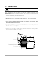
3.6
Loading Ribbon
To print with thermal transfer media, ribbon is required. The Ribbon Hub configuration will determine
the ribbon type (ink wound ‘in’ or ‘out’) that can be used in the printer. The directional arrows on the
Ribbon Loading Label indicate the way to route the ribbon through the printer.
&
Always use ribbon that is slightly wider than the media (and liner, if any) to protect against printhead wear.
Ribbon types are available with the coated (ink) layer wound ‘in’ or ‘out.’ These are NOT interchangeable
for use with the printer.
Load ribbon into the printer as follows:
1. With the access cover open and the Head Lift Lever raised, position a ribbon to be dispensed in the
direction appropriate for the Ribbon Supply Hub, as indicated in the figures below.
2. Slide a roll of ribbon on the Ribbon Supply Hub until it rests against the hub’s flange.
3. Route the ribbon under the Lower Idler, out the front of the printer, over the Ribbon Shield and Upper
Idler, then up around to the Ribbon Take-Up Hub.
4. Place the ribbon on the Ribbon Supply Hub then turn the hub several times in the direction of take-up
(see arrows on the Ribbon Loading Label) to secure the ribbon.
5. Lower the Head Lift Lever back into the locked position. Close the access cover.
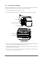
3.6.1
Removing Ribbon
When the ribbon supply is exhausted, grasp the used ribbon on the Ribbon Take-Up Hub, then while
pulling outward, squeeze together the collapsible hub and pull off the ribbon. Next, pull the empty core
from the Ribbon Supply Hub and discard it.
A-Class
35
‘Coated Side In’ Ribbon Routing Diagrams
Ribbon
Take-Up Hub
Ribbon
Loading Label
Ribbon
Take-Up Hub
Ribbon
Loading Label
Head Lift Lever
Head Lift Lever
Ribbon
Supply Hub
Upper Idler
Ribbon
Supply Hub
Upper Idler
Ribbon Shield
Ribbon Shield
Lower Idler
Left-Hand Model - CSI
36
Lower Idler
Right-Hand Model -CSI
A-Class
‘Coated Side Out’ Ribbon Routing Diagrams
Ribbon
Loading Label
Ribbon
Take-Up Hub
Ribbon
Loading Label
Ribbon
Take-Up Hub
Head Lift Lever
Head Lift Lever
Ribbon
Supply Hub
Upper Idler
Ribbon
Supply Hub
Upper Idler
Ribbon Shield
Ribbon Shield
Lower Idler
Left-Hand Model - CSO
A-Class
Lower Idler
Right-Hand Model - CSO
37
38
A-Class
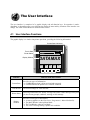
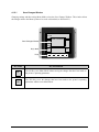
The User Interface
The user interface is comprised of a graphic display and soft-function keys. Its operation is modedependant, so depending upon your selections the displayed items and key functions of the interface can
change. All of the various modes are detailed in this section.
4.1
User Interface Functions
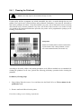
The graphic display is a window into printer operations, providing the following information:
Current State Indicators
Time & Date
Printer Status
Display Window
TUE 11:55 A 04 FEB 2003
PAUSED
DATAMAX
MENU
Indicator
COMM
PAUSED
PAUSE
FEED
CANCEL
TES T
Indicator Item and Function
Current State
Provides two types of information:
COMM indicates data is being received and processed.
PAUSE indicates the printer is in a ‘Paused’ condition.
Time & Date
The current settings for Time and Date.
Printer Status
Following initialization, the ‘Ready’ message and a label counter during a batch print
job, but also any prompt, condition, warning, or fault message.
Display
Window
A-Class
Provides several types of information:
A start-up graphic (see the Class Series Programmer’s Manual for details).
The Menu Window when in Menu Mode.
The Test Window when in Test Mode.
The FAULT message during a printer fault condition.
39
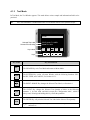
4.1.1
Ready Mode
In Ready Mode, the printer is idle, waiting to accept data for label printing.
TUE 11:55 A 04 FEB 2003
READY
DATAMAX
Key Labels
MENU
PAUSE
FEED
CANCEL
TEST
Keys
Key Label
MENU
Key and Function
The MENU Key takes the printer Offline and enters Menu Mode. (When shaded, this
denotes that security is enabled and now a password must be entered. See Section
4.2.1.)
Note: While in Ready Mode, pressing and holding this key will adjust the display
contrast. It can take up to fifteen seconds to cycle through the entire contrast
range.
40
PAUSE
The PAUSE Key temporarily suspends printing, as noted by the Current State
Indicators. Pressing the key again will return the printer to normal operation.
FEED
The FEED Key advances one label, and clears any corrected faults. Also, pressing
and holding this key causes the printer to perform a Quick Media Calibration; see
Section 5.5.1.
CANCEL
The CANCEL Key ‘pauses’ the printer and then prompts you for confirmation. If
yes, the current job is cancelled. The printer remains paused. Also, pressing and
holding this key four seconds will reset the printer and clear temporary host settings;
see Section 6.4.1.
TEST
The TEST Key enters the Test Mode; see Section 4.1.3. Pressing and holding this key
evokes the printhead cleaning routine; see Section 5.4.1. (When missing, this denotes
that security has been enabled; a password must be input to proceed. See Section
4.2.1.)
A-Class
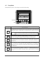
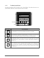
4.1.2
Menu Mode
In Menu Mode, the Menu Window appears. This mode allows the printer to be configured for your
application. Note that the Selected Menu Branch appears highlighted in a reverse field on the Menu
Window.
TUE 11:55 A 04 FEB 2003
OFFLINE
MENU WINDOW
Selected Menu Branch
Menu Branches
Key Labels
MEDIA SETTNGS
PRINT CONTROL
PRINTER OPTIONS
E SC
TEST
ENTER
Keys
Key Label
Key and Function
ESC
The ESCAPE Key exits the Selected Menu Branch. Repeatedly pressing the key
exits Menu Mode and returns the printer to Ready Mode.
TEST
The TEST Key enters the Test Mode; see Section 4.1.3. Pressing and holding this
key causes the printer to perform a printhead cleaning; see Section 5.4.1.
The DOWN ARROW Key selects the previous Menu Branch. (Not all branches
appear in the Menu Window at any one time.)
The UP ARROW Key selects the next Menu Branch. (Not all branches appear in the
Menu Window at any one time.)
ENTER
A-Class
The ENTER Key enters the Selected Menu Branch.
41
4.1.2.1
Save Changes Window
Changing settings and then exiting Menu Mode evokes the Save Changes Window. This window allows
the changes made to the Menu System to be saved or discarded (see Section 4.2.1).
TUE 11:55 A 04 FEB 2003
OFFLINE
MENU WINDOW
SAVE CHANGES?
Save Changes Window
Key Labels
DIAGNOSTICS
MEDIA SETTNGS
PRINT CONTROL
NO
YES
Keys
42
Key Label
Key and Function
NO
The NO Key exits Menu Mode without saving the changes that have been made to
the printer’s operating parameters.
YES
The YES Key saves the changes that have been made to the printer’s operating
parameters and then exits Menu Mode.
A-Class
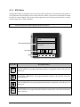
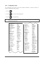
4.1.3
Test Mode
In Test Mode, the Test Window appears. This mode allows various sample and informational labels to be
produced.
Note: Test functions are disabled when the printer is processing data received from a communications port.
Also, when ‘SECURITY’ is enabled this function is not accessible until the correct password is input.
TUE 11:55 A 04 FEB 2003
OFFLINE
TEST WINDOW
Selected Test Label
Selected Test Quantity
Key Labels
PRINT QUALITY LABEL
QUANTITY 0002
E SC
S YSTEM
COUNT
E NTE R
Keys
Key Label
ESC
SYSTEM
Key and Function
The ESCAPE Key exits Test Mode and returns to Menu Mode.
The SYSTEM Key evokes a System Window with the following functions: ESC,
PAUSE, FEED, and CANCEL; see Section 4.1.3.1.
The RIGHT ARROW Key changes the Selected Test Label; see Section 4.4.
COUNT
The COUNT Key changes the Selected Test Quantity of labels in the following
amounts: 1, 10, 100, 1000, and 9999 (except the ‘Configuration Label’, which is
always one). Pressing and holding this key scrolls the quantities.
The ENTER Key will print the Selected Test Label at the Selected Test Quantity.
ENTER
&
A-Class
A printing time delay can be specified for this function using ‘Print Test Rate’; see
Section 4.2.7.
43
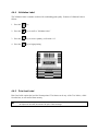
4.1.3.1
Test Mode System Window
Pressing the System Key while in Test Mode evokes a System Window. This window allows the user to
perform PAUSE, FEED, and CANCEL operations while in Test Mode.
TUE 11:55 A 04 FEB 2003
OFFLINE
SYSTEM WINDOW
DATAMAX
Key Labels
ESC
PAUSE
FEED
CANCEL
Keys
Key Label
ESC
The ESCAPE Key closes the System Window and returns to Test Mode.
PAUSE
The PAUSE Key temporarily suspends printing, as noted by the Current State
Indicators. Pressing the key again will return the printer to normal operation.
FEED
The FEED Key advances one label, and clears any corrected faults. Also, pressing
and holding this key causes the printer to perform a Quick Media Calibration; see
Section 5.1.1.
CANCEL
44
Key and Function
The CANCEL Key ‘pauses’ the printer and then prompts you for confirmation. If
yes, the current job is cancelled. The printer remains paused. Also, pressing and
holding this key four seconds will reset the printer and clear temporary host settings;
see Section 6.4.1.
A-Class
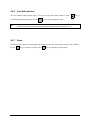
4.1.4
MCL Mode
Enabling MCL Mode in the Menu system executes the MCL application. This mode allows the printer to
accept input data from peripheral devices such as barcode scanners, weigh scales, and keyboards without
the need of a host computer. This printer-resident application can also request and send data to locally
resident lookup files or remote databases.
Note: The MCL program is a custom application that has been developed by your MCL Certified provider.
Consult your provider for details regarding operation and support.
TUE 11:55 A 04 FEB 2003
OFFLINE
MCL
MCL Operating Menu
System Menu
1. Run Program
Key Labels
ES C
ENTER
Keys
Key Label
Key and Function
ESC
The ESCAPE Key has program dependent operation, and typically returns to the previous
menu level.
The DOWN ARROW Key has program dependent operation, and typically selects the
next menu item.
The UP ARROW Key has program dependent operation, and typically selects the previous
menu item.
ENTER
A-Class
The ENTER Key has program dependent operation, and typically selects the current menu
item or function.
45
4.2
The Menu System
Printer operation can be controlled through the user interface from the following six menu system
branches:
•
Media Settings
•
Print Control
•
Printer Options
•
System Settings
•
Communications
•
Diagnostics
While in the menu system, the current selection will be indicated with an asterisk (*) next to the displayed
item. Selections designated with a section symbol (§) will require a printer reset before becoming
effective. A reset will be automatically invoked when exiting the menu system and answering ‘Yes’ to the
‘Save Changes’ prompt. Changes made will be saved. When power is removed, the new settings will be
restored upon power-up.
The same functional commands from your host computer may, in some cases, override the printer’s menu
settings. In addition, the menu system has a password protection feature to prevent accidental or
unauthorized parameter changes; see Section 4.2.5: System Settings / Security for details.
Notes: (1) In the following subsections, the factory default settings are denoted with the ‘ ’ symbol. Selections
denoted with a diamond (♦) can only be changed through the menu system – all other selections can
be overridden by host software commands. Consult the Class Series Programmer’s Manual for specific
information.
(2) For PE users converting to the A-Class, a Menu Constraint Cross-Reference, which details the
differences between the printer menu items and functions, has been included in Appendix C.
46
A-Class
4.2.1
Entrance and Exit Prompts
To change the setup parameters of the printer via the User Interface, enter Menu Mode by pressing the
MENU Key.
Depending upon enabled security settings or changes to the setup, the following Entrance and Exit
Prompts may be displayed when accessing or leaving Menu Mode:
Note:
While in Menu Mode, the printer stops processing new data.
Displayed Menu Item
MENU MODE
ENTER PASSWORD
0000
Explanation
Accesses the printer’s Menu System.
You are attempting to enter Menu Mode. Security has been enabled
and now the correct user-definable password is required before
access can be gained to the Menu.
Using the and Keys, enter the correct numeric password. (The
ENTER Key sets the (flashing) number then advances the cursor
one space to the right.) After the correct number has been input,
press the ESC Key to enter Menu Mode.
SAVE CHANGES?
You are now exiting Menu Mode, but have made changes to the
printer’s settings. Pressing YES will reconfigure your printer
according to these changes; otherwise, pressing NO will cause the
printer to revert to previously saved settings.
Note: If changes have been made that require a reset, the printer will
automatically invoke that reset.
A-Class
47
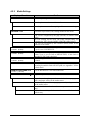
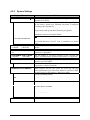
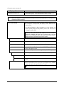
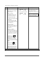
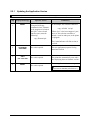
4.2.2
Media Settings
Displayed Menu Item
MEDIA TYPE
DIRECT THERMAL
THERMAL TRANSFER
SENSOR TYPE
GAP
CONTINUOUS
REFLECTIVE
LABEL LENGTH
04.00in (0-99.99)
MAXIMUM LABEL LENGTH
16.00in (0-99.99)
PAPER OUT DISTANCE
00.25in (0-99.99)
Details
Selects the printing method.
Sets the printer to use heat sensitive media.
Sets the printer to use media requiring a ribbon to create an image.
Selects the top-of-form (TOF) sensing method for the media.
TOF will be recognized by the gaps (die-cut) or notches in the
media.
No TOF sensing will be used. The Label Length setting will
determine the TOF. (See the LABEL LENGTH setting, below.)
TOF will be recognized by the reflective (black) marks on the
underside of the media.
This value will determine the length of the label when the Sensor
Type is set to CONTINUOUS .
Sets the maximum length allowable between TOF marks (when the
Sensor Type is set to GAP or REFLECTIVE). If this limit is
exceeded, a TOF Fault is declared.
Sets the length of media travel before an Out Of Stock Fault is
declared.
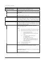
LABEL WIDTH
Sets the maximum distance for the printable width. Objects
extending beyond this limit will NOT print; see Appendix C for the
default values.
RIBBON LOW DIAMETER
Sets the threshold for a low ribbon indication.
1.40 in (1.00-2.00)
SENSOR CALIBRATION ♦
Adjusts the printer to sense the media inserted in the Media Sensor.
PERFORM CALIBRATION
Steps the user through a procedure to calculate the empty, gap (or
mark), and paper values for the media sensor.
Allows direct inputs of the empty, gap (or mark), and paper values
for the media sensor.
Sets threshold values for the media sensor parameters via manual
entry.
Adjusts the sensitivity of the sensor for custom label stock via
manual entry.
ADVANCED ENTRY
SENSOR LEVELS
SENSOR GAIN
48
A-Class
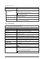
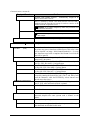
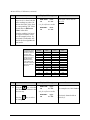
Media Settings (continued)
Displayed Menu Item
Details
PRINTHEAD CLEANING
Controls the printhead cleaning routine.
CLEAN HEAD SCHEDULE
000 in. (* 1000)
Specifies the inch (or centimeter) count to reach before prompting a
printhead cleaning. If the number specified is exceeded three times,
the printer will fault until cleaning is initiated.
Note: The number specified is multiplied by one thousand. Zero (the
default value) disables this function.
CLEAN HEAD COUNTER
0 in.
RESET COUNTER
CLEAN HEAD NOW
4.2.3
&
Indicates the number of inches (or centimeters) since printhead
cleaning was last initiated.
Resets the Clean Head Counter to zero.
Initiates printhead cleaning and resets the Clean Head Counter. See
Section 5.4.1 for detailed instructions.
Print Control
Refer to Section 2.2 for print quality information.
Displayed Menu Item
HEAT
10 (0-30)
Details
Controls the ‘burn-time’ of the printhead. This is the equivalent of
Heat Setting on most label software programs.
PRINT SPEED
Controls the rate of label movement during the printing process; see
Appendix C for range.
FEED SPEED
Controls the rate of label movement when the FEED Key is pressed
and between printing areas; see Appendix C for range.
REVERSE SPEED
Controls the rate of label movement during backup positioning for
start of print, cutting or present distance; see Appendix C for range.
SLEW SPEED
Controls the rate of label movement between printing areas using
the GPIO function; see Appendix C for range.
ROW OFFSET
Shifts the vertical start of print position. This is the user setting for
row adjustment.
00.00in (0-99.99)
COLUMN OFFSET
00.00in (0-99.99)
PRESENT DISTANCE
0.00in (0-4.00)
Shifts the horizontal, left-justified start of print position to the right
without shifting the Label Width termination point to the right.
This is the user setting for Column Adjust.
Sets the label stop position past the start of print position. When
the next label format is received, the printer will automatically
backfeed to the start position. If the present distance is set to zero,
the printer will operate without reversing.
Note: The default distance for the A-4212 is .65 inches.
A-Class
49
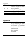
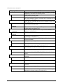
Print Control (continued)
Displayed Menu Item
Details
CUSTOM ADJUSTMENTS ♦
These factory adjustments independently change the listed
parameters to finely tune the printer and compensate for slight
mechanical differences sometimes evident if multiple printers share
label formats.
Controls the strobe time to establish the nominal HEAT setting for
printhead-specific thermal characteristics.
Allows fine-tuning of the relative print edge (gray) adjustment for
print quality.
Shifts the vertical start of print position in dots upward or
downward to fine-tune the ROW OFFSET setting; see Appendix C.
Shifts both the horizontal start of print position and the LABEL
WIDTH termination point to the right in dots to fine-tune the
COLUMN OFFSET setting; see Appendix C.
Adjusts the label stopping position in dots to fine-tune the
PRESENT DISTANCE setting; see Appendix C.
DARKNESS
32
(1-64)
CONTRAST
32
(1-64)
ROW ADJUST
000 DOTS
COLUMN ADJUST
000 DOTS (0-128)
PRESENT ADJUST
064 DOTS (0-128)
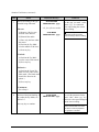
4.2.4
Printer Options
Displayed Menu Item
MODULES
PRINT DIRECTORY
PRINT FILE
FORMAT MODULE
DELETE FILE
PACK MODULE
50
Details
Memory available for user storage of graphics, fonts and label
formats. (The physical presence of the respective memory module
must be detected to show the function selections in the menu
system. See Appendix C for a listing of all possible modules.)
Prints a label directory of selected, or of all available modules, the
available space on these modules, the files present, and the type of
module and files.
Selects from a list of available stored files for printing.
Selects from a list of available modules for formatting. Note that all
existing module data will be erased.
Selects from a list of available files for deleting. (Protected modules
will not appear, and bytes will not be retrieved until the module
containing the deleted file is packed.)
Removes files marked as deleted, and defragments existing file
structures to recover space.
A-Class
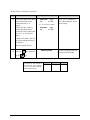
Printer Options (continued)
Displayed Menu Item
CUTTER
AUTO
ENABLED
DISABLED
RIBBON SAVER
AUTO
ENABLED
DISABLED
SCANNER
MODE
AUTO
ENABLED
DISABLED
A-Class
Details
Option used to cut media into separate labels.
Automatically senses the presence of the cutter. If present, the cutter
is enabled. If not detected, the cutter is ignored.
Enables the cutter. The presence of the cutter must be detected or
read errors are generated.
Disables the cutter.
Option used to conserve ribbon when the label contains areas of no
print (white space).
Automatically senses the presence of the ribbon saver option. If
present, the option is enabled. If not detected, the option is ignored.
The presence of the ribbon saver option must be detected or read
errors are generated.
Disables ribbon saving.
Option used to check linear bar codes in the picket-fence orientation
(bar codes perpendicular to the label’s leading edge).
Enables bar codes to be read by the Scanner.
Automatically senses the presence of the scanner. If present, the
scanner is enabled to read bar codes. If not detected, the scanner is
ignored.
The presence of the scanner must be detected or read errors are
generated.
Disables the scanner.
51
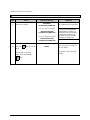
Printer Options (continued)
Displayed Menu Item
BARCODES
Details
Enables the scanner to read the respective bar code. Also see
Appendix B.
Note: To speed throughput and decoding integrity only enable the
symbologies that you will be reading.
CODE 39
IATA
Enables or disables Code 39.
Enables or disables IATA.
CODABAR
Enables or disables Codabar.
INTERLEAVED 2 OF 5
Enables or disables Interleaved 2 OF 5.
INDUSTRIAL 2 OF 5
Enables or disables Industrial 2 OF 5.
CODE 93
Enables or disables Code 93.
CODE 128
Enables or disables Code 128.
MSI/PLESSEY
Enables or disables MSI/Plessey.
EAN(13/8)
Enables or disables EAN(13/8).
EAN(13/8)+2
Enables or disables EAN(13/8) + 2 digit addendum.
EAN(13/8)+5
Enables or disables EAN(13/8) + 5 digit addendum.
UPC(A/E)
Enables or disables UPC(A/E).
UPC(A/E)+2
Enables or disables UPC(A/E) + 2 digit addendum.
UPC(A/E)+5
Enables or disables UPC(A/E) + 5 digit addendum.
BARCODE COUNT
00
(0-99)
Sets the specific number of bar codes to be read on the label.
00 selects AUTO Mode, allowing a variable number of bar codes to
be read per label format.
Note: AUTO Mode should not be used with imaged (bitmapped) bar
codes or with certain bar code addendums; see Appendix B for a listing.
52
A-Class
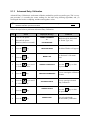
Printer Options (continued)
Displayed Menu Item
MIN READABLE HEIGHT
Details
Ensures bar code integrity by selecting the vertical distance of the
bar code that must have identical reads. The printer will calculate
the scan rate and the number of required consecutive reads based on
the selected height and print speed.
Note: The selected distance should not exceed 50% of the measured
bar code height.
1/16 in
(1.5 mm)
Ensures that 1/16 inch of the bar code is 100% readable.
2/16 in
(3.0 mm)
Ensures that 1/8 inch of the bar code is 100% readable.
3/16 in
(4.5 mm)
Ensures that 3/16 inch of the bar code is 100% readable.
1/4 in
(6 mm)
Ensures that 1/4 inch of the bar code is 100% readable.
1/2 in
(12.5 mm)
Ensures that 1/2 inch of the bar code is 100% readable.
DISABLED
When ‘Disabled’ is selected, the printer defaults to REDUNDANCY
LEVEL.
REDUNDANCY LEVEL
Ensures the data integrity of the bar code. The selected level
determines the number of consecutive, identical decodes that are
required to pass the bar code (i.e., if set to three times, the bar code
will not pass until it has been decoded with the same value three
successive times.)
Note: Depending upon the print speed, higher verification levels may
cause erroneous failures when scanning multiple bar codes or bar codes
that are small in height. Refer to the documentation supplied with the
Scanner for the exact number of scans at a given print speed.
READ BARCODE (1X)
READ BARCODE (2X)
Two consecutive, identical decodes are required per bar code.
READ BARCODE (3X)
Three consecutive, identical decodes are required per bar code.
READ BARCODE (4X)
Four consecutive, identical decodes are required per bar code.
READ BARCODE (5X)
Five consecutive, identical decodes are required per bar code.
READ BARCODE (6X)
Six consecutive, identical decodes are required per bar code.
SET DEFAULTS
A-Class
One decode is required per bar code.
Resets the current settings of the Scanner to the default settings.
53
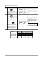
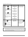
Printer Options (continued)
Displayed Menu Item
GPIO PORT
GPIO DEVICE
Used to interface the printer to external controlling devices (see
Appendix D).
Sets the GPIO Port to work with a specific type of device.
APPLICATOR
Enables the GPIO for a label applicator.
BARCODE VERIFIER
Enables the GPIO for a bar code verifier.
DISABLED
START OF PRINT
ACTIVE LOW
ACTIVE HIGH
END OF PRINT
ACTIVE LOW
Disables the GPIO Port.
Programmable signal input that controls the Start of Print (SOP)
process.
SOP signal must go ‘low’ for at least 50 milliseconds to initiate
printing.
SOP signal must go ‘high’ for at least 50 milliseconds to initiate
printing.
Programmable signal output that signifies the End of Print (EOP)
process.
Outputs a logic ‘low’ following printing.
ACTIVE HIGH
Outputs a logic ‘high’ following printing.
LOW PULSE
Outputs a low pulse (approximately 30 milliseconds long) following
printing.
Outputs a high pulse (approximately 30 milliseconds long)
following printing.
Programmable signal output that signifies the RIBBON LOW
DIAMETER condition; see Section 4.2.2.
Outputs a logic ‘high’ when the ribbon reaches the Ribbon Low
Diameter setting.
Outputs a logic ‘low’ when the ribbon reaches the Ribbon Low
Diameter setting.
HIGH PULSE
RIBBON LOW
ACTIVE HIGH
ACTIVE LOW
54
Details
A-Class
4.2.5
System Settings
Displayed Menu Item
Details
CONFIGURATION FILE ♦
Options for storage and recall of printer configuration files. See
Appendix F for details.
Provides a list of available configuration files. Selecting a file from
the list causes a printer reset; afterward, the printer is configured
according to the activated file.
Saves the entire effective configuration of the printer to a file.
Unique names with up to nineteen characters are possible.
Provides a list of available configuration files. Files selected are
immediately removed, freeing the module.
RESTORE AS CURRENT
SAVE SETTING AS
DELETE FILE
Note: A currently activated file cannot be deleted.
FACTORY SETTING FILE
INTERNAL MODULE
1024 KB
(100-5120)
DEFAULT MODULE
D
SCALEABLE FONT CACHE
0312 KB
(100-5120)
SINGLE BYTE SYMBOLS
PC_850 MULTILINGUAL
DOUBLE BYTE SYMBOLS
UNICODE
Provides a list of available configuration files. The selected file will
be restored whenever a Level 1 reset is performed; see Section
6.4.1.
Sets the number of 1K blocks allocated for the internal RAM ‘D’
module.
Sets the default module used to store files when no other module is
specified; see Appendix C.
Sets the number of 1K blocks allocated for the scaleable font
engine. Available memory dependent upon model; see Appendix C.
Selects the code page used to print single byte fonts unless
otherwise specified in DPL.
One of 66 selectable standard sets; see the Class Series
Programmer’s Manual for details.
When equipped with the ILPC option, this selects the code page
used to print double byte fonts unless otherwise specified in DPL;
see the Class Series Programmer’s Manual for details.
Unicode (including Korean)
GB
Government Bureau Industry Standard; Chinese (PRC)
BIG 5
Taiwan encoded
JIS
Japanese Industry Standard
SHIFT JIS
Shift Japanese Industry Standard
EUC
Extended UNIX Code
TIME AND DATE
A-Class
Allows the user to set the printer’s time and date.
55
System Settings (continued)
Displayed Menu Item
MEDIA COUNTERS ♦
ABSOLUTE COUNTER
Details
Internal record of inches printed and time of use.
RESETTABLE COUNTER
Shows the number of inches printed since being set at the factory.
Not resettable.
The number of inches printed since the last reset. User may reset.
RESET COUNTER
Resets the Resettable Counter to zero.
PRINT CONFIGURATION
Prints the effective configuration of the system. In addition, if
settings were changed that require a reset to become effective, this
will be indicated with the ‘§’ symbol. A bulleted item (•) indicates
that it was changed via the host, but not yet saved in Flash memory.
CONFIGURATION LEVEL ♦
To upgrade the application program (resident software) version of
the printer, the hardware and software compatibility levels must
match for the update to be accepted. This information is displayed
here and on the configuration label.
Identifies the unique key number of the printer, in the form:
PRINTER KEY
vvvv-cwxx-yyyyyy-zzz
Where:
vvvv
Represents the model number of the application loaded
cwxx
Represents the hardware/software feature level, where:
c – represents the printer class.
w
–
xx –
yyyyyy
zzz
Is a manufacturing date code
Is a unique time stamp
APPLICATION VERSION
Displays the Application version of the printer’s firmware.
BOOT LOADER
Displays the Boot Loader version of the printer’s firmware.
UPGRADE PRINTER CODE
Used to upgrade the software feature level of the printer. Datamax
authorization is required.
Used to unlock the additional optional features within the printer.
Datamax authorization is required.
UNLOCK FEATURE
56
represents hardware feature level of the main
board.
represents the software feature level:
10 = Standard DPL
20 = Internal CG Times Font
(Software features are accepted up to the ‘xx’
value - increases beyond that will require an
authorization code).
A-Class
System Settings (continued)
Displayed Menu Item
Details
SET FACTORY DEFAULTS
Parameters in this menu listing with the ‘ ’ symbol are the
designated defaults.
Restores the current settings to the factory defaults or, if selected,
the Factory Setting File.
SET FACTORY DEFAULTS
Note: The reset will be automatic. If no Factory Setting File is used,
all menu settings (except HEAD BIAS, CUSTOM ADJUSTMENTS and
calibrations) will be restored.
FORMAT ATTRIBUTES
XOR
OPAQUE
TRANSPARENT
BUZZER
ENABLED
DISABLED
HEAD BIAS
Affects the manner in which overlapping text and graphics are
treated. See the Class Series Programmer’s Manual for details.
Intersecting text, images, and bar codes will not be printed (but an
odd number of overlapping objects will print.)
Intersecting text, images, and bar codes are obliterated by those
formatted last (each character is treated as opaque).
Intersecting text, images, and bar codes print on top of one another.
Audible signaling device that sounds to acknowledge User
Interface entries and, if enabled, printer warning and fault
conditions.
Turns ‘On’ the buzzer for warning and fault conditions.
Turns ‘Off’ the buzzer for warning and fault conditions.
Switches the dot zero orientation. (The dot zero left / right
reference point is given relative to the label output side of the
printer).
WARNING: Switching this setting will cause the printer to reverse all
of the media movement directions.
STANDARD
RIGHT HAND
LABEL ROTATION ♦
ENABLED
DISABLED
A-Class
X origin is the leftmost location of the printhead; printing is left
justified.
X origin is the leftmost location of the label width; printing is right
justified.
Rotates the label format 180 degrees before printing.
Flips label formats from top to bottom.
Formats are printed normally.
57
System Settings (continued)
Displayed Menu Item
IMAGING MODE
Details
Determines the pre-imaging process of the label format.
Note: This selection can affect the accuracy of time-stamped labels
and label throughput.
MULTIPLE LABEL
SINGLE LABEL
PAUSE MODE
ENABLED
DISABLED
PEEL MODE
ENABLED
DISABLED
SECURITY ♦
SELECT SECURITY
MENU AND TEST
SECURE MENU
DISABLED
MODIFY PASSWORD
Images multiple labels as memory permits, achieving the fastest
throughput; however, if time-stamping, the time will reflect the
moment the label is imaged rather than when actually printed.
Images the next label only after the previous label has been
successfully printed. Single processing provides time-stamps that
are more accurate, but it slows label throughput time.
Allows the printer to suspend printing between each label until the
PAUSE Key is pressed.
Requires an operator to press the PAUSE Key after each label.
Completes label batches without pausing between labels.
Specifies that the printer is to wait for the GPIO Start of Print
signal.
Inhibits the feed function until the Start of Print signal is received.
The feed function is always enabled.
Provides the user with the ability to password-protect all settings
available through the User Interface.
Enables or disables the security feature of the User Interface.
The Menu and Test areas will require a password before access is
granted (these buttons will be shaded, indicating that security is
enabled).
The Menu area will require a password before access is granted (the
button will be shaded, indicating that security is enabled).
All menu items are accessible without protection.
Modifies the numeric password required to access the menu system
when security is enabled. You will be prompted to enter a new
password.
Enter a password using the
and
Keys. (The ENTER Key sets
the current [flashing] number then shifts the cursor to the right.)
After the password has been input, press the ESC Key.
When prompted to ‘CONFIRM NEW PASSWORD,’ enter the same
numeric password to proceed with the change.
58
A-Class
System Settings (continued)
Displayed Menu Item
UNITS OF MEASURE
IMPERIAL
METRIC
Details
Selects the measurement system in which the system’s settings are
represented in the menu system and on configuration labels.
Lengths and counters given in inches.
Lengths are given in millimeters and counters in centimeters.
INPUT MODE
Defines the type of printer processing.
DPL
Standard DPL processing.
LINE
Standard DPL processing with additional Line Mode template
processing enabled. Line Mode exacts data terminated by a carriage
return to be inserted in a DPL template and printed.
SOP EMULATION
110 (PRODPLUS)
Enables the <STX>O and <STX>f print positioning commands to
allow backward compatibility with label formats designed for other
printers. (When changing these values, the printer will
automatically feed two labels to setup the new print position.)
No emulation: natural start of print position. (System Commands
<STX>O and <STX>f are ignored).
Emulates the Prodigy Plus® printer.
220 (ALLEGRO)
Emulates the Allegro® printer.
250 (PRODIGY)
Emulates the Prodigy ™ printer.
DISABLED
BACK AFTER PRINT
ENABLED
DISABLED
BACKUP DELAY (1/50 S)
000
(0 – 255)
FONT EMULATION
STANDARD FONTS
When a Present Distance is set with GPIO enabled, this determines
the timing of the label back up.
Immediately backs-up the label after the applicator issued Start of
Print signal is received for faster throughput.
Initiates repositioning only when the next label is ready to print.
May help prevent the curling of the label edge.
Instructs the printer to automatically retract a presented label after
the specified time delay elapses. Units are selectable in fiftieths of a
second. Zero indicates retraction only when the next label is
received and processed to print.
This setting allows font substitution for all Datamax internal fonts.
See Appendix B for examples.
Prints using standard available fonts. See Appendix B for examples.
CG TIMES
Prints using CG Times fonts only.
USER ID S50
Prints using a downloaded font only.
A-Class
59
System Settings (continued)
Displayed Menu Item
LABEL STORE
STATE & FIELDS
FIELDS ONLY
MENU LANGUAGE ♦
ENGLISH
FAULT HANDLING
LEVEL
STANDARD
VOID AND RETRY
Details
When recalling stored label formats, this setting determines the
command recall level used.
Recalls the printer state (that is, the heat setting, speed settings, etc)
and the label-formatting commands of the stored label.
Recalls only the label-formatting commands of the stored label.
Selects the language in which the menu system messages and
configuration label are shown. Only languages that are resident will
be shown. See Appendix E for downloading information.
English
When a fault condition (ribbon out, media out, etc.) is detected, this
setting determines the level of intervention and the disposition of
the label being printed at the time the fault occurred.
Selects the printer’s action, the action required by the operator, and
the label’s reprint status.
Printing stops and a fault message is displayed. After the problem is
corrected, the FEED Key must be pressed to clear the fault. The
label in process is reprinted.
Depending upon the RETRY COUNT, one of the following actions
when faulted:
• If the Retry Count setting has not been exceeded, ‘VOID’ is
printed on the label in process and reprinting occurs
automatically; or,
• If the Retry Count has been exceeded, printing stops and a fault
message is displayed. After the problem is corrected, the FEED
Key must be pressed to clear the fault. The label in process is
reprinted; or,
• If the CANCEL Key is pressed the operator now has a reprint
option: To allow a reprint, press the ESCAPE Key; or, to cancel
the reprint, press the ENTER Key (and, to cancel the entire batch
by press the ENTER Key again.)
Notes: 1) If a Linear Scanner is not attached, this menu item will
cause the printer to perform as it does in the Standard fault handling
setting (see above), except that VOID will be printed on the faulted
label. 2) VOID will not be printed when insufficient space exists for the
height of the text (see VOID DISTANCE, below) or if the fault occurred
after the entire label was completed (i.e., when the label reaches its
Present Distance at or above the TOF). 3) The Void Message can be
customized, see the Class Series Programmer’s Manual for
downloading details.
NO REPRINT
60
Printing stops and a fault message is displayed. After the problem is
corrected, the FEED Key must be pressed to clear the fault. The
label in process is not reprinted.
A-Class
System Settings (continued)
Displayed Menu Item
Details
VOID DISTANCE
0.50 in (.10-2.00)
Sets the distance to backup the faulted label to print ‘VOID’ on its
trailing edge, which also indirectly establishes the font size of the
void message.
RETRY COUNT
1
(0-3)
Establishes the number of times the printer will attempt to reprint a
label. If the last label printed in this count has been voided, the
printer will stop and display a fault message.
Note: Retry counts above 1 are only valid for printers equipped with
the Linear Scanner option.
A-Class
61
4.2.6
Communications
Displayed Menu Item
SERIAL PORT A
BAUD RATE
38400
28800
19200
9600
4800
2400
1200
PROTOCOL
BOTH
SOFTWARE
HARDWARE
NONE
PARITY
NONE
ODD
EVEN
DATA BITS
7
8
STOP BITS
1
2
Details
Controls the communications settings for Serial Port A.
Determines the serial communication rate.
38400 bits per second
28800 bits per second
19200 bits per second
9600 bits per second
4800 bits per second
2400 bits per second
1200 bits per second
Sets the data flow control (handshaking) method.
Uses both handshaking methods.
XON/XOFF.
CTS/DTR.
No flow control is used.
Sets Word parity.
No parity.
Odd parity.
Even parity.
Sets Word length.
Seven-bit Word length.
Eight-bit Word length.
Sets the number of stop bits.
One stop bit
Two stop bits
SERIAL PORT B
This port controls the communications settings for the Aux Serial
Port on the Applicator Interface Card. The available settings are
the same as those for the Serial Port A, above.
PARALLEL PORT A
Controls the communications settings for Parallel Port A.
PORT DIRECTION
UNI-DIRECTIONAL
BI-DIRECTIONAL
62
Determines if data is sent from the printer to the host via the
parallel port.
One-way printer communication.
Enables IEEE 1284 back-channel operation.
A-Class
Communications (continued)
Displayed Menu Item
PARALLEL PORT B
Details
Same as Parallel Port A, for an optional Ethernet connection. If not
present, this displays ‘NOT INSTALLED’ when accessed.
Note: If ‘LOCKED’ appears when attempting to access the NIC ADAPTER submenu, the printer may have
active print requests or multiple users may be trying to access these parameters (for example, during
simultaneous telenet sessions).
NIC ADAPTER♦
DMXNet and DMXrfNet are the optional Network Interface Card
(NIC) Adapters. If not present, this displays ‘NOT INSTALLED’
when accessed.
After making changes to these parameters, save the changes, exit
the menu system, and cycle the printer’s power ‘Off’ and ‘On’ for
the changes to take effect.
Note: The boot process (taking up to two minutes) must be completed
at power-up. During this time, the NIC Adapter will not be accessible or
configurable; "DMXNET INACTIVE" will be indicated when in the menu
system or on a Configuration Label. After this process, you will be able to
configure the options provided using the menu system.
IP ADDRESS
SUBNET MASK
The static IP address of the NIC Adapter in standard dotted-decimal
format.
The static subnet assigned to the NIC Adapter.
GATEWAY
Specifies the network gateway address the NIC Adapter should use.
SNMPTRAP DESTINATION
Selects the Network IP address where all SNMP Traps will be sent.
If zeroed, no traps are sent.
Sets the network protocol to be recognized by the NIC Adapter.
PROTOCOL
NETWARE
ENABLED
DISABLED
DISCOVERY
Allows the printer to be driven from an NDS Novell Print Queue.
NetWare is enabled by default.
Ignores the NetWare protocol. Select this option if NetWare is not
needed.
This is the address discovery method used by the card if a static
address is not utilized. If no server for any of the discovery methods
is found, the static value specified above is used.
Note: For faster NIC Adapter boot times, disable any discovery
methods not used.
A-Class
63
Communications (continued)
Displayed Menu Item
DHCP
ENABLED
Details
Dynamic Host Control Protocol. Automatically assigns an IP
address from a DHCP Server.
DHCP is enabled by default. This means that the card will send a
broadcast into the network on start-up in order to receive an IP
Address from the responsible server.
WARNING: An IP Address assigned by DHCP has precedence over
any stored static IP Address.
DISABLED
Disables DHCP.
Note: Select this option to ensure that any stored static IP is used by
the NIC Adapter.
SET FACTORY DEFAULTS
HOST SETTINGS ♦
HOST TIMEOUT
10 SEC
(1-60)
CONTROL CODES
STANDARD CODES
ALTERNATE CODES
ALTERNATE CODES 2
CUSTOM CODES
FEEDBACK CHARACTERS
ENABLED
DISABLED
ESC SEQUENCES
ENABLED
DISABLED
64
Restore the current NIC Adapter settings to the factory defaults.
Settings that affect all communications with a host.
The number of seconds a communications port must be idle before
the printer may process data from a different port. This value is also
used to “timeout” an image / label format download (i.e., if, at any
time, data flow stops before a complete label format is received, the
data will be ignored).
Allows the operator to change the prefix of the software commands
interpreted by the printer.
Hex 01 = SOH command; Hex 02 = STX command; count-by = ^;
Hex 1B = ESC; Hex 0x0D = Carriage Return
Hex 5E = SOH command; Hex 7E = STX command; count-by =
@; Hex 1B = ESC; Hex 0x0D = Carriage Return
Hex 5E = SOH command; Hex 7E = STX command; count-by =
@; Hex 1B = ESC; Hex 0x7C = Carriage Return
Each DPL command (SOH, STX, CR, and count-by) may be
selected by entering the desired Hex code. (The and Keys will
scroll the characters, while the ENTER Key selects character and
then advances the cursor.)
Returns a Hex 1E, [RS], after each label successfully prints, and a
Hex 1F, [US], after each batch of labels is printed.
Feedback characters are sent to the host.
No feedback characters are sent.
Allows data containing invalid ESC control code sequences to be
processed; helpful since some systems send a “banner” to the
printer.
Normal printer operating mode.
ESC sequences are ignored and the data is processed. Bitmapped
font downloads are disabled in this mode.
A-Class
Communications (continued)
Displayed Menu Item
HEAT COMMAND
ENABLED
DISABLED
SPEED COMMANDS
ENABLED
DISABLED
TOF SENSING COMMANDS
ENABLED
DISABLED
SYMBOL SET COMMAND
ENABLED
DISABLED
CNTRL-CODES (DATA)
ENABLED
DISABLED
STX-V SW SETTINGS
ENABLED
DISABLED
MAX LENGTH COMMAND
ENABLED
DISABLED
A-Class
Details
Allows the user to disable the DPL Heat Command, providing
compatibility with other DATAMAX printers.
Normal printer operating mode.
DPL Heat command is ignored. The heat value is controlled via the
menu setting; see Section 4.2.3.
Allows the user to disable the DPL speed commands (Print, Feed,
Slew, and Reverse).
Normal printer operating mode.
DPL speed commands are ignored. The speeds are controlled via
the menu setting; see Section 4.2.3.
Allows the user to disable the DPL Top of Form commands (Gap,
Continuous, and Reflective).
Normal printer operating mode.
DPL TOF commands are ignored. The TOF is controlled via the
menu setting; see Section 4.2.2.
Allows the user to disable the DPL Single and Double Symbol Set
selection commands.
Normal printer operating mode.
DPL Symbol Set commands are ignored. The Symbol Set selection
is controlled via the menu setting; see Section 4.2.5.
Allows the user to remove control codes (data < 20 Hex) from the
data fields. The selected line terminator is processed.
Normal printer operating mode.
DPL Control Code (SOH, STX, CR, ESC, and ^) functions are
ignored.
Allows the user to disable the DPL software switch setting
commands.
Normal printer operating mode.
DPL option-enable command (<STX>V) is ignored.
Allows the user to disable the DPL maximum label length
command.
Normal printer operating mode.
The DPL <STX>M command is ignored. Maximum label length is
controlled via the menu setting; see Section 4.2.2.
65
4.2.7
Diagnostics
Displayed Menu Item
HEX DUMP MODE ♦
ENABLE
DISABLE
OPTIONS TESTING ♦
TEST CUTTER
PERFORM TEST
1 TIME
TEST RIBBON SAVER
PERFORM TEST
1 TIME
TEST GPIO
MONITOR GPIO INPUT
SOP FEED PAUSE REPRT
1
1
1
1
Details
Most commonly used for troubleshooting. Prints data and
instructions received from the host rather than interpreting them as
label formats; see Section 6.3.
Prints raw ASCII data received from the host rather than executing
the commands.
Executes and prints label formats (normal operating mode).
Allows or performs diagnostics of specific options within the
printer.
Performs a functional test of the cutter.
The test will cycle the selected number of times (1, 10, or 100; use
the
and
Keys) with the results displayed following each
attempt.
Performs a functional test of the ribbon saver circuits and
mechanisms.
The test will cycle the selected number of times (1, 10, or 100; use
the
and
Keys) with the results displayed following each
attempt.
Performs a functional test of the General Purpose Input Output
interface. See Appendix D.
Input values are displayed for the SOP (Start of Print), Feed, Pause,
and Reprint lines.
Note: Unconnected lines may display a zero or one value.
TEST GPIO OUTPUT
EOP RL SR MO RO DRDY
0
0
1
1
1
1
LOOPBACK
Output logic values are reported, where:
EOP = End of Print;
RL = Ribbon Low;
SR = Service Required;
MO = Media Out;
RO = Ribbon Out; and,
DRDY = Data Ready.
(The
and
Keys toggle the output state, while the
Key
advances the cursor.) See Appendix D for the GPIO Port pin-outs.
Performs an internal test of the GPIO Port circuitry.
Note: Before executing this test, remove any connection to the GPIO
Port.
PRINT SIGNAL INFO
66
Prints a label containing GPIO Port signal names, programmed
settings, and current states. See Appendix D for a sample of the
label.
A-Class
Diagnostics (continued)
Displayed Menu Item
TEST SCANNER
Performs a functional test of the optional linear scanner.
SCAN TEST
ALIGNMENT TEST
PRINT TEST RATE (min) ♦
000
(0-120)
SENSOR READINGS ♦
THR TRAN RIB M 24V HD RANK
255 255 255 255 255 255
RIBBON SENSOR LIMITS ♦
RIBBON ADC LOW HIGH
070 164
4.2.8
Enters a “read once mode.” A bar code is read and the decoded
results are displayed.
Enters a “constant read mode.” Bar codes are read; decoded results
are displayed; and, the read-count is incremented.
The number of minutes to delay between the printings of batches of
Test Labels.
Analog Sensor readings are displayed.
Live sensor values are displayed. Maximum values are shown in
this example, where:
THR = thermistor sensor;
TRAN = transmissive (gap) media sensor (REFL is shown when
SENSOR TYPE is set to ‘reflective’);
RIB M = ribbon motion sensor;
24V = 24 volt DC power supply sensor;
HD = head-down sensor; and,
RANK = the value of the printhead ranking resistor.
Displays ribbon sensor ADC low and high values used for motion
detection.
Approximate default values are shown here (actual values will
vary).
MCL Options
Displayed Menu Item
MCL AT POWER-UP ♦
ENABLED
DISABLED
START MCL ♦
A-Class
Details
Details
MCL (Macro Command Language) is a tool suite designed for data
collection applications. The printer will accept input data from
peripheral devices and the application can request and send data to
locally resident lookup files or remote databases.
After power to the printer is turned ‘Off’ and ‘On,’ MCL Mode will
be started. The printer is now ready to accept input data from
peripheral devices such as barcode scanners, weigh scales, and
keyboards without the need of a host computer; see Section 4.1.4.
Normal printer functions.
MCL Mode will be started after exiting the menu; see Section
4.1.4.
67
4.3
Printer Messages
The printer displays several different types of information (if not in Menu or Test Mode):
Enter and Exit Prompts; see Section 4.2.1
Alert Prompts and Condition Messages; see Section 4.3.1.
Application and Boot Loader Updating Messages; see Sections 5.5 and 5.6.
Fault and Warning Messages; see Section 6.2.
4.3.1
Alert Prompts and Condition Messages
Alert Prompts appear when an action is required of the operator, while Condition Messages are used to
indicate an operational state of the printer.
Prompts and Condition Messages
Displayed Message
!CLEARING FAULTS
!
CALIBRATING
CANCEL REPRINT
ENTER KEY = YES
!
CANCEL BATCH
ENTER KEY = YES
!
DMXNET INITIALIZING!
OFFLINE
PAUSED
68
Description
Cause(s)
The printer is trying to clear a fault
condition.
The FEED Key was pressed after a
fault.
Media calibration is being
performed.
The FEED Key was pressed and
held.
The current label will not be
reprinted if the ENTER Key is
pressed. (Any labels remaining in the
batch will be printed.)
The CANCEL or TEST Key was
pressed during the fault handling
process.
The remaining labels in the current
batch will not be printed if the
ENTER Key is pressed.
The CANCEL or TEST Key was
pressed during a batch job.
Normal power-up and soft reset
condition when equipped with the
DMXNet or DMXrfNet option.
The network card is initializing.
Depending upon the programmed
settings, this process can take up to
two minutes.
The printer is in Menu or Test Mode.
The Menu or Test Key has been
pressed.
The printer is paused.
The PAUSE Key has been pressed
or Paused Mode has been selected.
A-Class
Prompts and Condition Messages (continued)
Displayed Message
Description
Cause(s)
Indicates the menu item cannot be
enabled.
The option is not installed or cannot
be detected by the printer.
PRINTHEAD CLEANING
Indicates that printhead cleaning is in
progress.
The TEST Key was pressed and
held, or ‘CLEAN HEAD NOW’
was selected.
READY
Normal operating mode. The printer
is ready to receive label formats,
downloads, etc.
The printer is in Ready Mode.
NOT INSTALLED
REMOVE RIBBON
PRESS ANY KEY
SYSTEM INITIALIZING
SUCCESSFUL
PRESS ANY KEY
SYSTEM RESET
IN PROGRESS
!UNCALIBRATED!
WAITING FOR DATA
!
WAITING FOR SIGNAL!
XXXX OF XXXX PRINTING
!
A-Class
In order to initiate printhead
cleaning, ribbon must be removed.
The TEST Key was pressed and
held, or ‘CLEAN HEAD NOW’
was selected.
Normal power-up and soft reset
condition.
Follows the ‘SYSTEM RESET IN
PROGRESS’ message after a reset
or power-up.
Printhead cleaning was successfully
completed.
The TEST Key was pressed and
held, or ‘CLEAN HEAD NOW’
was selected.
Normal power-up and soft reset
condition.
The user has reset the printer via the
host or User Interface.
The media calibration must be
performed; see Section 5.1.
The printer is not calibrated.
A Start of Print signal has been
received.
The printer is waiting for label data
to be supplied by the host.
A label is waiting to be printed.
The printer is waiting for the Start
of Print signal to be supplied by the
applicator.
The print job is being processed.
The printer is updating the batch
status, showing beginning and
remaining label counts.
69
4.4
Test Mode
The internally generated Test Labels are printed at pre-selected speed and heat settings. Changes to these
label settings can be made from the Menu System or via software commands.
Notes:
(1) Except as noted, use full width media to capture the entire format; otherwise, adjust the Label Width (Section
4.2.2) and Leveling Cam settings (Section 5.2.1) to the media’s width.
(2) In Test Mode, press the ESC Key or the TEST Key to stop printing.
(3) A printing time delay can be set (see Print Test Rate, Section 4.2.7).
4.4.1
Print Quality Label
The Print Quality Label is a general indicator of overall print quality. The format, consisting of compliant
fence and ladder bar codes, assorted sizes of fonts, and graphic fill patterns, can be used to ensure
conformance, as well as aesthetics. Generate a Print Quality Label as follows:
1. Press the
TEST
Key.
Key to scroll to ‘Print Quality Label.’
3. Press the
4. Press the
COUNT
Key to select a quantity; see Section 4.1.3.
5. Press the
ENTER
Key to begin printing.
70
A-Class
4.4.2
Configuration Label
The Configuration Label provides current printer database information, as detailed in Section 4.2.
Generate a Configuration Label as follows:
1. Press the
TEST
Key to scroll to ‘Print Configuration.’
2. Press the
3. Press the
Key.
ENTER
Key to begin printing.
Notes: (1) The information on this label may vary with the printer model, firmware version and options. (2) To
capture all data, use media that is at least 2 inches (51 mm) wide and adjust the Label Width setting
accordingly (see Section 4.2.2).
CONFIGURATION
WED 09:09 AM 5MAY2004
PRINTER KEY:
4310-AC 10-031029-958
APPLICATION VERSION:
83-2401-08D 8.03 06/04/2004
MCL Version:1.04
BOOT LOADER:
83-2405-08A 08.00 10/13/2003
FORMAT ATTRIBUTES
XOR
BUZZER
ROW OFFSET
USB PORT
HEAD BIAS
COLUMN OFFSET
LABEL ROTATION
PRESENT DISTANCE
PARALLEL PORT A:
PORT DIRECTION
IMAGING MODE
CUSTOM ADJUSTMENTS:
DARKNESS
ENABLED
STAN DAR D
DISABLED
MULTIPLE LABEL
SYSTEM INFORMATION
PRINT BUFFER SIZE:
242 in.
FLASH SIZE:
4 MB
RAM TEST:
PASS
OPTIONAL LANGUAGES:
NONE
CONFIGURATION FILE:
NON E
MEDIA SETTINGS
PAUSE MODE
DISABLED
PEEL MODE
DISABLED
SELECT SECURITY
DISABLED
UNITS OF MEASURE
IMPERIAL
INPUT MODE
0.00 in.
32
CONTRAST
32
ROW ADJUST
0 DOTS
COLUMN ADJUST
0 DOTS
PRESENT ADJUST
64 DOTS
STANDARD
BACK AFTER PRINT
DISABLED
SENSOR TYPE
FONT EMULATION
0
STANDARD FONTS
PRINTER OPTIONS
MODULES
D: FORMATTED
F: NOT IN STALLED
G: FORMATTED
X: FORMATTED
Y: 83-2296-03A
Z: NOT IN STALLED
CUTTER
LABEL LENGTH
LABEL STORE
MAXIMUM LABEL LENGTH
MENU LANGUAGE
RIBBON SAVER
PAPER OUT DISTANCE
FAULT HANDLING:
LEVEL
SCANNER
04.00 in.
16.00 in.
00.25 in.
LABEL WIDTH
4.10 in.
RIBBON LOW DIAMETER
1.40 in.
SENSOR CALIBRATION
PAPER SENSOR LEVEL
102
GAP SENSOR LEVEL
25
TRAN SEN SOR LEVEL
6
REFL PAPER LEVEL
102
MARK SENSOR LEVEL
40
REFL SENSOR GAIN
15
EMPTY SENSOR LEVEL
7
CLEAN HEAD SCHEDULE
000 in. (* 1000)
CLEAN HEAD COUNTER
000 in. (* 1000)
PRINT CONTROL
HEAT
10
PRINT SPEED
8.0 in/sec
FEED SPEED
6.0 in/sec
REVERSE SPEED
4.0 in/sec
SLEW SPEED
INSTALLED
UNI-DIRECTION AL
PARALLEL PORT B:
NOT INSTALLED
NIC ADAPTER:
IP ADDRESS
010.012.000.211
SUBNET MASK
255.255.000.000
GATEWAY
010.012.254.254
IP
EN ABLED
APPLETALK
EN ABLED
SOP EMULATION
BACKUP DELAY (1/50s)
GAP
00.00 in.
DPL
MEDIA TYPE
THERMAL TRANSFER
00.00 in.
STATE & FIELDS
ENGLISH
STAN DARD
VOID DISTANCE
0.50 in.
RETRY COUNT
1
COMMUNICATIONS
SERIAL PORT A:
BAUD RATE
NOT INSTALLED
EN ABLED
NOT INSTALLED
GPIO PORT:
GPIO DEVICE
ENABLED
BOTH
NONE
D
SCALEABLE FONT CACHE
312 KB
PROTOCOL
DOUBLE BYTE SYMBOLS
8
STOP BITS
1
ENABLED
ENABLED
EN ABLED
ENABLED
STX-V SW SETTINGS
EN ABLED
MAX LENGTH COMMAND
EN ABLED
1024 KB
SINGLE BYTE SYMBOLS
NONE
ENABLED
HEAT COMMAND
EN ABLED
9600 BPS
DATA BITS
ESC SEQUENCES
CONTROL CODES (DATA)
SYSTEM SETTINGS
DEFAULT MODULE
PARITY
DISABLED
SYMBOL SET COMMAND
ACTIVE HIGH
STOP BITS
BOTH
STANDAR D CODES
FEEDBACK CHARACTERS
RIBBON LOW
INTERNAL MODULE
1
10 SEC
CONTROL CODES
TOF SENSING COMMANDS
ACTIVE LOW
DATA BITS
SERIAL PORT B:
BAUD RATE
DISABLED
HOST SETTINGS:
HOST TIMEOUT
END OF PRINT
FACTORY SETTING FILE
8
DISABLED
DHCP
SPEED COMMANDS
ACTIVE LOW
PARITY
NONE
DISABLED
LAN MANAGER
START OF PRINT
9600 BPS
PROTOCOL
NETWARE
PC-850 MU LTILIN GUAL
UNICOD E
ABSOLUTE COUNTER
108535 in.
01MAR2003
RESETTABLE COUNTER
535 in.
01MAR2003
DIAGNOSTICS
HEX DUMP MODE
D ISABLED
PRINT TEST RATE (min)
0
SENSOR READINGS
THR TRAN RIBM 24V
093 110 041 115
PS HD RANK
000 092 179
RIBBON SENSOR LIMITS
R IBBON ADC LOW
255
R IBBON ADC HIGH
041
6.0 in/sec
MCL OPTIONS
MCL AT POWER-UP
DISABLED
A-Class
71
4.4.3
Quick Ribbon Test Label
The Quick Ribbon Test Label is an indicator of thermal transfer print quality. Generate a Quick Ribbon
Test Label as follows:
1. Press the
TEST
Key.
Key to scroll to ‘Ribbon Test Label.’
2. Press the
3. Press the
COUNT
Key to select a quantity; see Section 4.1.3.
4. Press the
ENTER
Key to begin printing.
72
A-Class
4.4.4
Validation Label
The Validation Label is another useful tool for establishing print quality. Generate a Validation Label as
follows:
1. Press the
TEST
Key to scroll to ‘Validation Label.’
2. Press the
3. Press the
4. Press the
4.4.5
Key.
COUNT
ENTER
Key to select a quantity; see Section 4.1.3.
Key to begin printing.
Print Last Label
Print Last Label reprints the last label format printed. The format can be any of the Test Labels, a label
from the host, or one recalled from memory.
Note:
A-Class
If a job was cancelled prior to its completion, or if power has been removed since the last print job and
the request for this label, this selection will print a ‘VOID’ message.
73
4.4.6
User Defined Label
The User Defined Label reprints from a list of previously printed label formats. Use the
scroll through the listing, and then use the
ENTER
Key to
Key to select and print the label.
Note: If a job was cancelled prior to its completion, or if power has been removed since the last print job and
the request for this label, ‘NO FILES AVAILABLE’ will be displayed and no printing will occur.
4.4.7
Demo
The Demo mode displays a rotating globe and sample system fonts in the graphic display center window.
Use the
74
TEST
Key to return to test mode or the
MENU
Key to return to the system menu.
A-Class
Adjustments and Maintenance
5.1
Media Sensor Calibration
Calibration ensures consistent label detection across the range of media types.
5.1.1
Quick Calibration
Perform the Quick Calibration during initial printer set-up or after changing the media to fine-tune the
media sensor’s gap and label values.
&
This procedure is not required for continuous media.
If ‘Uncalibrated’ is displayed, follow the Media Sensor Calibration procedure in Section 5.1.2..
1. Ensure that media is correctly loaded (see Section 3.4), that the Media Sensor is properly adjusted
(see Section 3.5), that the Sensor Type has been correctly selected (see Section 4.2.2), and that the
printer is in an idle state.
2. Press and hold the
FEED
Key. Media will begin to advance.
3. Allow the printer to output at least two complete labels before releasing the
FEED
Key.
Upon successful completion, the ‘Calibration Completed’ message will flash; the printer will feed to the
next label TOF and ‘Ready’ will be displayed. (A ‘Warning Low Backing’ message may appear if using
notched media or media on a transparent liner; however, the calibration was successful).
Note: Media containing large gaps may require a change in the ‘Paper Out Distance’ setting before Quick
Calibration; see Section 4.2.2.
Calibration Hints: With certain media, the printer may have trouble differentiating between the label and
liner. If ‘Cannot Calibrate’ is displayed, try calibrating over a longer distance, as follows:
•
Press and hold the
FEED
Key until the printer has output three (or more) labels.
If this method also fails (that is ‘Cannot Calibrate’ is displayed again), perform the Standard Calibration
(Section 5.1).
A-Class
75
5.1.2
Standard Calibration
Perform the Standard Calibration when ‘Cannot Calibrate’ or ‘Uncalibrated’ is displayed. During the
process, the printhead assembly can be raised for visual access. In addition, displayed sensor readings can
be used to indicate the best position over the media, which is helpful when using small, position-critical
TOF notches or marks. Three readings are required:
•
Empty:
No media in the sensor.
•
TOF Mark:
Only the backing, notch, or reflective mark in the sensor.
•
Paper:
The label (with the liner attached) in the sensor.
Follow the steps below to perform a Standard Calibration:
Step
Action
Turn ‘On’ the printer.
1
Wait until the printer
initializes (about six seconds).
Displayed Message
CANNOT CALIBRATE
-Or-
Press the
MENU
Key.
MEDIA SETTINGS
3
Press the
ENTER
Key.
MEDIA TYPE
4
Press the
SENSOR CALIBRATION
Press the
ENTER
Press the
ENTER
Key.
Remove the media from the
Media Sensor then press any
key.
76
See Section 4.2.2 for menu
items.
Press the
ESC
PERFORM CALIBRATION
You are beginning the
calibration procedure.
!REMOVE LABEL STOCK
Sets the ‘empty’ value - where
‘yyy’ is a numerical value
representing the current sensor
reading.
Key.
6
The Menu Window will
appear.
Key to abort this procedure.
to ‘Sensor Calibration’.
5
(Media should be loaded and
the ‘Sensor Type’ set.)
UNCALIBRATED
2
Key to scroll
Comment
PRESS ANY KEY <yyy>
A-Class
Standard Calibration (continued)
Step
7
Action
Displayed Message
Proceed according to the type
of media being calibrated:
SCAN BACKING
PRESS ANY KEY <yyy>
!
- Or, for reflective media:
Die-cut:
a) Remove a label or two
from the liner material.
b) Reinstall the media.
!
!
SCAN MARK
PRESS ANY KEY <yyy>!
!!
!
Comment
Sets the ‘gap’ (or ‘mark’) value
- where ‘yyy’ is a numerical
value representing the current
sensor reading.
Note: Never position a
perforation under the sensor
when recording a sensor reading.
c) Place only the liner under
the sensor.
d) Position the Eye Mark
over the middle of the liner.
e) Press any key.
Notched:
a) Position the Eye Mark
over the center of the notch.
b) Press any key.
Reflective:
a) Position the Sensor Eye
Mark over the center of the
black mark. (The black mark
should face down in the
printer.)
b) Press any key.
Continuous:
Go to Step 8.
8
Position a label (and backing, if
any) under the Eye Mark; see
Section 3.5.
Press any key to continue.
A-Class
SCAN PAPER
PRESS ANY KEY <yyy>
!
!
This sets the parameter for the
‘paper’ value - where ‘yyy’ is a
numerical value representing the
current sensor reading.
Note: If using preprinted stock,
ensure that the label area under
the sensor is free of preprinted
text, graphics or borders.
77
Standard Calibration (continued)
Note: Do not move the position of the Media Sensor after it has been adjusted.
Step
9
Action
Displayed Message
Observe the display.
Comment
GAP MODE
CALIBRATION COMPLETE
The calibration was successful.
- Or, for reflective media:
Note: If ‘Warning Low Backing’
is displayed (most typical with
notched media or media on a
transparent liner), the message
indicates that calibration was
successful. For other possible
messages see Section 6.2.
!
REFLECTIVE MODE
CALIBRATION COMPLETE
- Or, for continuous media:
CONTINUOUS MODE
CALIBRATION COMPLETE
!!
!
10
Press the
ESC
Key to exit the
READY
menu.
If using gap or reflective
media, press and hold the
FEED
78
!
Allow the printer to output at
least two labels.
The printer is ready to begin
printing.
Key.
A-Class
5.1.3
Advanced Entry Calibration
Advanced Entry Calibration is an alternate calibration method for special-case media types. This is a twopart procedure: (1) recording the sensor readings for the label using differing algorithms; and, (2)
selecting the best result, re-sampling, and then entering those values.
&
Advanced Entry Calibration will override all previous calibration settings. Use this method ONLY if the
Standard Calibration procedure has failed.
Follow the steps below to perform an Advanced Entry Calibration:
Step
1
Action
Displayed Message
Turn ‘On’ the printer.
CANNOT CALIBRATE
-Or-
Wait until the printer
initializes (about six seconds).
Press the
MENU
Key.
MEDIA SETTINGS
3
Press the
ENTER
Key.
MEDIA TYPE
4
Press the
Key to scroll
SENSOR CALIBRATION
to ‘Sensor Calibration’.
Press the
6
Press the
ENTER
Press the
PERFORM CALIBRATION
Key.
Key to scroll
ENTER
The Menu Window will appear.
See Section 4.2.2 for menu
items.
Press the
ESC
Key to abort
this procedure.
ADVANCED ENTRY !
to ‘Advanced Entry’.
7
(Media should be loaded and
the ‘Sensor Type’ set.)
UNCALIBRATED!
2
5
Comment
SENSOR LEVELS
!!
Key.
You are entering the calibration
submenu.
You are entering Advanced
Entry Calibration.
Press the
ESC
Key to abort
this procedure.
8
A-Class
Press the
Key.
SENSOR GAIN!
!
!
You are beginning the
Advanced Entry Calibration.
79
Advanced Entry Calibration (continued)
Step
Action
Press the
9
ENTER
Displayed Message
GAIN TRAN
<yyy>
*00
<0 – 32>
Key.
Place the label under the
Sensor Eye Mark and lower the
Head Lift Lever.
Press the
ENTER
- Or, for reflective media:
GAIN REFL
<yyy>
*00
<0 – 32>
If using preprinted media,
ensure the label area under the
sensor is free of text, graphics,
lines, etc.
!
Key to select
the Gain Number (denoted by
an ‘*’) and then record the
sensor reading (‘yyy’) as a
Label Value in a table similar
to the one shown below.
GAIN TRAN
<255>
*00
<0 – 32>
- Or, for reflective media:
10
Next, press the
Comment
GAIN REFL
<255>
*00
<0 – 32>
Key to
increment the Gain Number.
The sensor reading, where ‘yyy’
is a numerical value
representing the current sensor
reading, is useful in locating the
best sensor position over the
media.
Note: Never position the
sensor over a perforation when
recording a sensor reading.
!
!
Repeat this step to find the
Label Value for each of the
Gain Numbers (00-32).
Sample table:
Make a table similar
to the one shown
right, with enough
rows to record the
data for each of the
33 Gain Numbers.
80
Gain
Number
00
01
02
…
32
Label
Value
255
TOF
Value
Difference
Value
A-Class
Advanced Entry Calibration (continued)
Step
11
Action
Displayed Message
Two Parts, A & B:
GAIN TRAN
<yyy>
*00
<0 – 32>
Part A: Proceed according to
your media type:
Die-cut Media:
a) Remove a label or two
from the liner material.
- Or, for reflective media:
!!
!
GAIN REFL
<yyy>
*00
<0 – 32>
Comment
Where ‘yyy’ is a numerical
value representing the current
sensor reading: useful in
locating the best sensor position.
Note: Never position the
sensor over a perforation when
recording a sensor reading.
b) Reinstall the media.
c) Place only the liner under
the sensor.
d) Position the Eye Mark
over the middle of the liner;
see Section 3.5.
Notched Media:
Position the Eye Mark over
the center of the notch; see
Section 3.5.
Reflective Media:
Position the Eye Mark over
the center of the black mark;
see Section 3.5. (The black
mark must be facing down.)
Part B: Press the
ENTER
Key to
select the Gain Number
(denoted by an ‘*’) and then
record the sensor reading
(‘yyy’) in your table as a TOF
Value.
Next, press the
Key to
increment the Gain Number.
Repeat Part B of this step to
find the TOF Value for each of
the Gain Numbers (00-32).
Note: Do NOT move the position of the Media Sensor after it has been adjusted.
A-Class
81
Advanced Entry Calibration (continued)
Step
Action
12
From the data collected in
Steps 10 & 11, where both the
sensor readings are above 20,
subtract the Label Value from
the corresponding TOF Value.
Record these as Difference
Values in the table.
Displayed Message
Comment
Both sensor values must be
above 20.
GAIN TRAN
<014>
*32
<0 – 32>
- or, for reflective media:
GAIN REFL
<014>
*32
<0 – 32>!
From the resulting list, locate
the largest Difference Value
(see the example below). Its
associated Gain Number will
provide the best algorithm for
your media.
For example, if your
compiled data had
the values shown in
this table, Gain
Number 8 would be
chosen because it
has the highest
Difference Value
(146), where both
the Label Value and
the TOF Value are
above 20.
Step
13
Action
Using the
Key, select the
Gain Number determined in the
previous step.
Press the
ENTER
Key to select
Gain
Number
00
01
02
03
04
05
06
07
08
09
10
…
Label
Value
255
251
241
231
219
212
200
189
178
167
156
…
TOF
Value
254
240
213
182
150
119
88
58
32
19
17
…
Difference
Value
1
11
28
49
69
93
112
131
146
N/A
N/A
…
31
32
116
112
14
14
N/A
N/A
Displayed Message
GAIN TRAN
<yyy>
*08
<0 – 32>
- Or, for reflective media:
GAIN REFL
<yyy>
*08
<0 – 32>!
Comment
This example uses Gain Number
8.
Selection is denoted with an
asterisk (*).
the setting.
82
A-Class
Advanced Entry Calibration (continued)
Step
Action
Displayed Message
14
a) Place the media in the Media
Sensor. Record the sensor
reading and label it ‘P’
(paper).
GAIN TRAN
<yyy>
*08
<0 – 32>
b) Place the liner, mark, or
notch in the Media Sensor.
Record the sensor reading and
label it ‘G’ or ‘M’ (Gap or
Mark).
Comment
- or, for reflective media:
Where ‘yyy’ is a numerical
value representing the current
sensor reading.
GAIN REFL
<yyy>
*08
<0 – 32>!
c) Remove all media. Record
the sensor reading and label it
‘E’ (Empty).
(See the example below.)
15
Press the
by the
ESC
Key followed
Key.
For example, at Gain Number 8,
these were the sensor readings
for each of the media conditions.
(Actual readings will vary.)
A-Class
The sensor readings must now
be entered into the printer.
SENSOR LEVELS
Paper
Gap (or Mark)
Empty
198
084
014
83
Advanced Entry Calibration (continued)
Step
16
Action
a) Press the
ENTER
Displayed Message
PAPER SENSOR LEVEL
P* 198 G*000 E*000
Key.
the ‘Paper’ level to the value
determined in the previous
step.
c) Press the
ENTER
The selection will change to
indicate the item for entry.
GAP SENSOR LEVEL
P* 198 G*084 E*000
Key, set
b) Using the
Comment
EMPTY SENSOR LEVEL
P* 198 G*084 E*014
!
!
-Or, for reflective media:
!
PAPER SENSOR LEVEL
P* 015 G*000 E*000
Key to set
the entry (indicated by the
‘*’) and advance the menu.
d) Repeat for the ‘Gap’ (or
‘Mark’) value, and then the
‘Empty’ value.
GAP SENSOR LEVEL
P* 015 G*181 E*000
EMPTY SENSOR LEVEL
P* 015 G*181 E*213
!
!
!
17
Press the
ESC
SAVE CHANGES
ENTER KEY = YES!
Key to exit the
!
menu.
When prompted, press the
ENTER
Key to save your
From ‘Ready’, press the
FEED
Key. The printer will advance
the next label to the TOF
position. If a problem occurs,
see the note below.
changes and return to Ready
Mode.
Note: If the Advanced Entry Calibration fails, try the following procedure:
Re-enter the Menu. Go to
Media Settings
Calibration
Advanced Entry
Sensor
Gain and lower the selected Gain Setting number by one (to desensitize the sensor). Select the new Gain
Setting, save the changes, and exit the menu. Test your media at the new setting. If necessary, repeat the
procedure until a usable media setting is obtained.
84
A-Class
5.2
Printhead Adjustments
To ensure consistent print quality over the wide range of media types and sizes, the printer is equipped
with Leveling Cam and Burn Line adjustments.
5.2.1
Leveling Cam Adjustment
The Leveling Cam adjustment should be made to ensure even print quality whenever using media that is
narrower than the width of the printhead. Perform this adjustment as follows:
1. With media loaded and the Head Lift Lever locked down, download your label format to the printer
(or use a resident test format, see Section 4.4). To speed the process, print a batch of labels.
Head Lift Lever
Leveling Cam
2. As the labels are being printed, rotate the Leveling Cam to an over-adjusted position (see Example 1,
below).
A-Class
85
Example 1 – Over adjustment of the cam:
Too much adjustment produces an image that fades across the label. To
correct this, decrease the setting of the Leveling Cam.
3. Rotate the Leveling Cam, one click at a time, until the printed labels contain a complete, even image
(see Example 2, below).
Example 2 – Correct adjustment of the cam:
Proper adjustment produces a complete image, with even print contrast
across the label (see note below).
Note:Under-adjustment of the Leveling Cam can cause ribbon
wrinkling, lateral label movement, and excessive wear on the printhead
and platen roller.
86
A-Class
5.2.2
Burn Line Adjustment
The printer has been factory-adjusted using 6.5-mil (.0065 inch) media to ensure strict print quality
compliance across most types of label stock. In extreme cases, however, if media of a different thickness
or rigidity is used (for example, heavy tag stock), print quality may be affected. If print quality is not
acceptable, first try the suggestions in Sections 2.2, 2.3, and 5.2.1. If the problem continues, a Burn Line
adjustment may be needed.
&
If you have questions, regarding this procedure contact a qualified technician or Datamax Technical
Support before proceeding.
Adjust the Burn Line as follows:
1. Load the printer with the media (and ribbon, if required), as described in Section 3.4 (and Section 3.6
for ribbon).
2. Loosen the two Locking Screws on the Printhead Assembly approximately ¼ turn counter-clockwise.
Printhead Assembly
Locking Screws
Adjustment Screws
A-Class
87
3. Turn the Adjustment Screws counter-clockwise to bring the burn line forward, beyond the vertex of
the platen roller.
4. Print a Validation Label; see Section 4.4.4. (The label should have a light, uneven appearance.)
5. Tighten the Locking Screws until they are ‘snug’ (that is, tight enough to remove any play in the
printhead assembly, yet loose enough to allow the Adjustment Screws to move the printhead).
6. Turn each Adjustment Screw clockwise about a ¼ turn (or 1/8 a turn for finer adjustments, see note
below). (Typically, a thicker media requires a slight forward adjustment, while a thinner media
requires a backward adjustment). Print another Validation Label and examine the print quality.
Repeat this step until the print is produced with even contrast and acceptable quality across the width
of the label.
Note: When the Locking Screws are ‘snug’, turning the Adjustment Screws counter-clockwise will NOT
move the printhead outward. If you have adjusted the printhead too far inward, restart the entire
procedure.
7. Tighten the Locking Screws. Print a final Validation Label to verify the adjustment.
88
A-Class
5.3
Printhead Replacement
If the printhead becomes damaged, use the procedure below to replace the component.
(1) Use extreme care when handling the printhead; wear a wrist strap, and follow standard ESD
prevention procedures.
CAUTION
(2) If a voltage problem is suspected in the printhead failure (see “24V OUT OF TOLERANCE,”
Section 6.2) contact a qualified technician or Datamax Technical Support before proceeding.
Replace the printhead as follows:
1. Turn ‘Off’ and unplug the printer. Raise the Access Cover.
2. Touch a bare metal part of the printer’s frame to discharge any static electricity that may be present
on your body.
3. With the Printhead Assembly in the down position, loosen the Captive Screw(s) until the screw(s)
“pop(s) up”. Remove the Pivot Screw and Washers that secure the Printhead Assembly. The
following drawings highlight the location of these components according to the model of the printer:
Access Cover
Four-inch printer
models:
Printhead Assembly
Ground Cable
Screw
Pivot Screw
(and Washers)
Captive
Screw
A-Class
89
Access Cover
Six-inch printer
models:
Printhead Assembly
Ground Cable
Screw
Pivot Screw
(and Washers)
Captive
Screws
4. Raise the Head Lift Lever then slide the Printhead Assembly forward to access to the Ground Cable
Screw. Remove the Ground Cable Screw then slide the Printhead Assembly off the Pivot Shaft and
place the Printhead Assembly aside.
Head Lift
Lever
Pivot
Shaft
Printhead
Assembly
90
A-Class
5. Carefully disconnect both Printhead Cables, and then remove the old Printhead.
6. While carefully supporting the new Printhead to protect its surface, connect both Printhead Cables.
7. After ensuring that the Wavy Washer is in place, position the Printhead Assembly onto the Pivot
Shaft and, using the previously removed screw, reconnect Ground Cable to the Printhead Assembly.
Head Lift
Lever
Wavy
Washer
Printhead
Cables
Printhead
8. Slide the Printhead Assembly completely onto the Pivot Shaft and, using the previously removed
screw and washers, secure the Printhead Asssembly.
9. Place the Printhead onto the locating pins (on the underside of the Printhead Assembly). (As a
reference, use the Alignment Window in the Printhead Assembly to center the edge of the Printhead,
as shown below, then move the Printhead forward or backward to locate the pins.)
A-Class
91
Note: The drawing shown here is a
right hand model printer. On left hand
model printers, the Alignment Window
can be found on the opposite end of the
Printhead Assembly.
Printhead
Assembly
Alignment
Window
Printhead’s
Edge
Printhead
10. Secure the Printhead with the Captive Screw(s), but do not over-tighten.
11. Clean the Printhead using alcohol and allow it to dry; see Section 5.4.1.
12. Reload media, and ribbon (if removed), lower the Head Lift Lever into the locked position. Plug in
and turn ‘On’ the printer.
13. Print a Validation Label (see Section 4.4.4). Examine the printed label and, if necessary, adjust the
Darkness setting (see Print Control / Custom Adjustments in Section 4.2.3) so that the print contrast
(darkness) produced by the new Printhead matches the old Printhead.
Note: Following a printhead replacement, a Burn Line adjustment is NOT normally required. However, if print
quality has changed, see Section 5.2.2.
92
A-Class
5.4
Maintenance Schedule
The following list and table detail the recommended items, techniques, and schedules to help you safely
and effectively maintain the printer.
• Isopropyl alcohol
• Cotton swabs
• A clean, lint-free cloth
• Soft-bristle brush
• Soapy water/mild detergent
• Compressed air
• Printhead Cleaning Cards or Printhead Cleaning Film
For your safety and to avoid damaging the printer, turn ‘Off’ and unplug the printer before cleaning.
Always take proper precautions when using isopropyl alcohol, a flammable liquid.
CAUTION
Recommended Maintenance Schedule
Area / Item(s)
Cleaning Interval *
Printhead
Thermal transfer media – after each roll of ribbon.
Direct thermal media – after each roll of media, or
as needed.
Method / Supplies
Isopropyl alcohol; and, if
necessary, Printhead
Cleaning Cards or Printhead
Cleaning Film. See Section
5.4.1.
Rollers
After each roll of labels, after each roll of ribbon,
or as needed.
Cotton swab dampened with
isopropyl alcohol. See
Section 5.4.2.
Peel Assembly
After each roll of labels, after each roll of ribbon,
or as needed.
Cotton swab dampened with
isopropyl alcohol. See
Section 5.4.3.
Media Path /
Media Sensor /
Peel Bar
As needed, based on a weekly visual inspection.
Compressed air or a soft
brush. Isopropyl alcohol, as
needed. See Section 5.4.4.
Exterior Surfaces
As needed, based on a weekly visual inspection.
Mild detergent. See Section
5.4.5.
*Whichever interval comes first.
A-Class
93
5.4.1
Cleaning the Printhead
NEVER use a sharp object on the Printhead; damage can result.
CAUTION
If print quality declines (symptoms can include unreadable bar codes, or streaks through the text and
graphics), the typical cause is debris build-up on the printhead. Furthermore, if not removed, this build-up
may lead to premature dot failure. Clean the printhead every time a roll of ribbon has been used. If using
direct thermal stock, clean the printhead every time a roll of labels has been used, or as needed. To help
you remember this important maintenance procedure, the printer can be programmed to prompt you for
cleaning; see Section 4.2.2.
Faulty Label:
Instead of consistent patterns, streaks in the direction
of print indicate a dirty or faulty printhead. (To print
one of the resident test labels, see Section 4.4.)
According to the media, ribbon, and printing parameters used, different methods are recommended for
cleaning the printhead. In all cases, perform the following preliminary operations before cleaning the
printhead:
Preliminary Cleaning Steps:
1. Stop printing. Raise the Access Cover, and then raise the Head Lift Lever. Wait a minute for the
printhead to cool.
2. Remove media and ribbon from the printer.
Proceed according to your cleaning requirements.
94
A-Class
5.4.1.1
Cotton Swab Procedure
This procedure is for printers using direct thermal media, or thermal transfer media with a wax ribbon.
1. Perform the Preliminary Cleaning Steps, as described in Section 5.4.1.
2. Turn ‘Off’ and unplug the printer. Using a Cotton Swab moistened (not soaked) with isopropyl
alcohol, gently clean the entire Printhead surface, paying special attention to the Burn Line, until all
build-up is removed.
Access Cover
Head
Lift Lever
Printhead
Burn Line
Cotton Swab
debris build-up
example
3. Allow the printhead to dry.
4. Reinstall media (and ribbon, if necessary). Lockdown the Head Lift Lever. If necessary, adjust the
Leveling Cam. Close the cover. Plug in and turn ‘On’ the printer. Run a few sample labels and
examine them. If streaking is still present, go to Section 5.4.1.2; otherwise, this completes the
procedure.
A-Class
95
5.4.1.2
Cleaning Card Procedure
This procedure is for printers using direct thermal media, or thermal transfer media with a wax ribbon.
Also use this procedure if symptoms continue after the Cotton Swab Procedure (see Section 5.4.1.1) has
been tried.
1. Perform the Preliminary Cleaning Steps, as described in Section 5.4.1.
2. Place a Cleaning Card under the printhead. (Use part number 70-2013-01 for 4-inch model printers
and 70-2014-01 for 6-inch model printers.)
3. Lockdown the Head Lift Lever and disengage the Leveling Cam; see Section 5.2.1.
Cleaning
Card
Head Lift Lever
4. Close the access cover. Press and hold the
TEST
Key for approximately four seconds. (As an
alternate, ‘CLEAN HEAD NOW’ can be selected in the menu system, see Section 4.2.2.)
5. After the cleaning card has been run through the printer, reinstall media (and ribbon, if necessary).
Lockdown the Head Lift Lever. If necessary, adjust the Leveling Cam. Close the cover. Run a few
sample labels and examine them. If streaking is still present, go to Section 5.4.1.3; otherwise, this
completes the procedure.
96
A-Class
5.4.1.3
Cleaning Film Procedure
This procedure is for printers using a resin ribbon with thermal transfer media, or for printers that
typically use a Heat Value of 22 or higher. Also use this procedure if symptoms continue after the
previous method (see Section 5.4.1.2) has been tried.
1. Perform the Preliminary Cleaning Steps, as described in Section 5.4.1.
2. Place a sheet of Cleaning Film under the printhead. (Use part number 70-2087-01 for 4-inch model
printers; or, 70-2087-02 for 6-inch model printers.)
3. Lockdown the Head Lift Lever and disengage the Leveling Cam; see Section 5.2.1.
Cleaning
Film
Head Lift Lever
4. Close the access cover. Press and hold the
TEST
Key for approximately four seconds. (As an
alternate, ‘CLEAN HEAD NOW’ can be selected in the menu system, see Section 4.2.2.)
A-Class
97
5. After the cleaning film has been run through the printer, turn ‘Off’ and unplug the printer. Open the
Access Cover and raise the Head Lift Lever. Using a cotton swab moistened (not soaked) with
isopropyl alcohol, gently clean the entire Printhead surface. Allow the printhead to dry.
Access Cover
Head Lift Lever
Cotton Swab
Printhead
6. Reinstall media and ribbon. Lockdown the Head Lift Lever. If necessary, adjust the Leveling Cam.
Close the cover. Plug in and turn ‘On’ the printer. Run a few sample labels and examine them; if
streaking is still present, see Section 6.1.
98
A-Class
5.4.2
Cleaning the Rollers
NEVER use a sharp object to clean the Rollers.
CAUTION
Rollers contaminated with grit, label adhesive, or ink can cause a reduction in print quality. Label
tracking can also be affected. In extreme cases, labels may wrap the rollers. To prevent problems, clean
the rollers as follows:
1. Turn ‘Off’ and unplug the printer. Raise the access cover.
2. Raise the Head Lift Lever. Lower the Peel Assembly Release Lever. Remove media and ribbon.
3. Using a cotton swab dampened with isopropyl alcohol, clean the Rollers. Rotate each roller, wiping
and repeating until the entire roller is clean.
4. After allowing the Rollers to dry, replace ribbon and media. Close the Peel Assembly and lower the
Head Lift Lever into the locked position.
5. Close the access cover. Plug in and turn ‘On’ the printer. This completes the cleaning procedure.
Feed several labels to normalize media tracking.
Head Lift Lever
Rollers
Peel Assembly Release Lever
Peel Assembly
A-Class
99
5.4.3
Cleaning the Peel Assembly
Peel Rollers contaminated with grit and label adhesive can reduce the ability of the printer to separate the
labels from the backing material. To prevent problems, clean the rollers as follows:
1. Turn ‘Off’ and unplug the printer. Raise the access cover.
2. Raise the Head Lift Lever. Lower the Peel Assembly Release Lever. Remove media and ribbon.
Head Lift Lever
Peel Assembly Release Lever
Peel Assembly
Latch Roller
Knurled Roller
3. Using a cotton swab dampened with isopropyl alcohol, clean the Latch Roller and the Knurled Roller.
Rotate each roller, wiping and repeating until each entire roller is clean.
4. After allowing the rollers to dry, replace ribbon and media. Close the Peel Assembly and lower the
Head Lift Lever into the locked position.
5. Close the access cover. Plug in and turn ‘On’ the printer. This completes the cleaning procedure.
Feed several labels to normalize media tracking.
100
A-Class
5.4.4
Cleaning the Media Sensor, Media Path, and Peel Bar
When particles such as paper dust accumulate inside the printer, the result can produce small voids in the
text, graphics and bar codes. Also, adhesive build-up on the Peel Bar can impair label separation. To
prevent problems, clean these areas as follows:
1. Turn ‘Off’ and unplug the printer. Raise the access cover.
2. Raise the Head Lift Lever. Lower the Peel Assembly Release Lever. Remove media and ribbon.
Ribbon Shield
(thermal transfer-equipped
models only)
Media Posts
Peel Bar
Media Guide
Media Sensor
3. Using compressed air or a soft brush, clean the media path (and ribbon path, on units equipped with
the thermal transfer option) including the Media Sensor and Peel Bar. Use a cotton swab dampened
with isopropyl alcohol as needed on areas of heavy build-up.
4. After allowing the components to dry, replace media, and ribbon (if needed). Close the Peel
Assembly and lower the Head Lift Lever into the locked position.
5. Close the access cover. Plug in and turn ‘On’ the printer. This completes the procedure. Feed several
labels to normalize media tracking before printing.
A-Class
101
5.4.5
Cleaning Exterior Surfaces
The stainless steel surfaces of the printer should be cleaned using a general-purpose cleanser. Never use
abrasive cleansers or solvents. Clean the printer surfaces as follows:
1. Turn ‘Off’ and unplug the printer.
2. Using a soft cloth or sponge dampened with the cleanser, wipe the exterior surfaces clean.
3. Allow the surfaces to dry.
4. Plug in and turn ‘On’ the printer.
5.5
Application Program Updates
The printer stores its application program in Flash memory on the Main Logic Card. The printer allows
updates to this program version through any of its communications interfaces. Updates can be found at
ftp://ftp.datamaxcorp.com
Before updating, identify the current version of the printer’s application program by printing a
Configuration Label (see Section 4.4.2). Compare that version string to those filenames available from the
FTP site (see above) and then download the desired file onto your computer’s hard drive.
WARNING
102
Should an error occur during the download (see Section 5.5.2), the update is aborted. If this process
did not reach ‘Erasing Flash’ or ‘Updating Software’, the previous program is left intact; otherwise, a
successful download must be completed before the printer is operable.
A-Class
5.5.1
Updating the Application Version
Note: If Security has been enabled, disable the feature before proceeding (see Section 4.2.5).
Step
Displayed Message
1
!
READY
!
Operator Action
Using the DOS copy
command (where ‘filename’
is the program to be loaded
and ‘lpt1’ is the selected
interface port), enter the
following:
copy filename lpt1:
Comment(s)
As an example, this would be entered as:
copy A4212tb~1.zs lpt1
(Where ‘lpt1’ is the host computer’s port;
however, this selection can differ to
include a serial or other port, as the printer
is equipped.)
The Comm Indicator will flash as data is
received.
2
UPGRADING
SOFTWARE
No action required.
The new application program is being
stored and verified.
No action required.
The printer has automatically reset and is
now displaying the new firmware version.
!!
3
4
A4212
8.00 10/01/2003
!!
!!!
READY
No action required.
The new application is now running.
Note: If ‘Uncalibrated’ is displayed, the
printer must be calibrated (see Section 5.1).
A-Class
103
5.5.2
Possible Problems during an Update
The following is list of possible error messages when downloading:
Note: If experiencing trouble when attempting to download the file to the printer, try the following alternate
methods: 1) Windows® users – try restarting the computer in MS-DOS mode; or, 2) Use the Datamax
Printer Driver (found on the Accessories CD-ROM) – “Device Setting / Send File to Printer” function.
Application Update Error Messages
Displayed Message
Descriptions / Causes / Solutions
DECOMPRESSION
ERROR
!!
The printer detected an error during the decompression and transfer of file data
from cache storage into the Flash memory. Confirm the version and retry in
Download Mode; however, if the problem continues call for service.
ERROR ERASING
FLASH
!!!
The printer could not successfully erase Flash memory. The possible cause is
defective Flash memory. Try the download again; however, if the problem
continues call for service.
ERROR WRITING
FLASH
!!!
The printer could not successfully write the program into Flash memory. A
possible cause is defective Flash memory. Try the download again; however, if
the problem continues call for service.
HARDWARE
MISMATCH DATA
REJECTED
!
Application Firmware downloaded was not compatible with the printer’s Main
Logic Card. The firmware used was for a different class model and not
supported by this boot loader version. See Configuration Level, Section 4.2.5.
INVALID SOFTWARE
DATA REJECTED
!!
The printer detected an error in the download. The possible causes include:
• An invalid or corrupted file was downloading. (Try resaving the file to the
host and then download it again.)
• A communications error. (Recheck the cabling and the port settings.)
SOFTWARE
MISMATCH DATA
REJECTED
Software level not authorized for this printer (See Section 4.2.5, Configuration
Level/Printer Key.)
104
A-Class
5.6
Boot Loader Program Updates
The printer stores the Boot Loader Program in Flash memory on the Main Logic Card. A feature allows
updates to this program via the printer’s interface port. Updates can be found at
ftp://ftp.datamaxcorp.com.
If power is lost while ‘Upgrading Software’ is displayed, the printer will become non-functional and
must be returned to the factory for programming or the main logic board must be replaced.
WARNING
Before performing the Boot Loader update, identify the printer’s current version. Print a Configuration
Label (see Section 4.4.2) and compare that version string to those available from our FTP site. Download
the desired version onto your computer’s hard drive. To update the Boot Loader Program:
Note: If Security has been enabled, disable the feature before proceeding.
Step
Displayed Message
1
READY
!
Operator Action
Comment(s)
Using the DOS copy
command (where ‘filename’
is the program to be loaded
and ‘lpt1’ is the selected
interface port), enter the
following:
As an example, this would be entered as:
copy filename lpt1:
copy boottb~1.bs lpt1
(Where ‘lpt1’ is the host computer’s
output port; however, your selection can
differ to include a serial or other port, as
the printer is equipped.)
The Comm Indicator will flash as data is
received.
2
3
4
UPGRADING
SOFTWARE
3.173
A4212
4/01/2003
READY
!
No action required.
The new program is being stored and
verified.
No action required.
The printer has automatically reset.
No action required.
The new application is now running.
Note: If ‘Uncalibrated’ is displayed, the
printer must be calibrated (see Section 5.1).
A-Class
105
106
A-Class
Troubleshooting
This section describes problem resolution, and the methods used to reset the printer.
6.1
General Resolutions
The following table covers problems that may not generate a printer error message. From the listing,
locate the general description of the problem that best fits the symptom to find a solution.
&
If you have questions, or if problems persist, contact a qualified technician or Datamax Technical Support.
If experiencing this
problem…
Try this solution…
Can not communicate through
the parallel port:
Watch the display. The Comm Indicator (see Section 4.1) will flash as
data is received. If COMM does not appear, check the parallel cable
type; also, verify the protocol and port settings of the printer and host.
The graphic display is blank,
but the blue backlighting is
‘On’:
The display contrast may set too low. Turn the printer ‘Off’ and ‘On.’
Wait for ten seconds. (If the printer is equipped with at network card
wait for two minutes.) Press and hold the MENU Key. (It can take up
to 15 seconds to cycle through the contrast range, see Section 4.1 for
the menu key layout.)
Erratic feeding:
The printer may require a Quick Media Calibration; see Section 5.1.1.
Erratic printing (instead of the
label format, strange
characters are printed):
• The printer may be in Hex Dump Mode; see Section 6.3.
• If using serial communications, check the host and printer port
settings; the printer may be set to eight data bits while the host is set
to 7 (or vice versa).
Light print on the right or left
side of the label:
• The Leveling Cam may be incorrectly adjusted; see Section 5.1.1.
• The Head Lift Lever may not be locked; see Section 3.4.
• The Platen Roller may be dirty or worn; see Section 5.4.2.
A-Class
107
If experiencing this
problem…
Missing information in the
printed label:
Try this solution…
• Check the label format for character placement outside the
dimensions of the label; all row/column values must allow enough
space for the height/length of the characters and bar codes to be
printed within the format size.
• Available memory may have been exceeded by the requirement of
the label format. Try reducing the memory allocated to either the
internal module or scaleable font caches; see System Settings /
Memory Settings, Section 4.2.5.
• If using serial communications, ensure that the interface cable meets
the requirements found in Section 3.3.1.
Missing print on left or right
side of the label:
Information may be formatted outside the label dimensions. Check
your software program label size or check the values in the menu for
Print Control / Column Offset and Print Control / Custom Adjustments
/ Column Adjust; see Section 4.2.3.
Unable to print rotated text:
The characters may be formatted outside the label dimensions. Ensure
the row/column values provide enough room for the height of the
characters or bar code to be printed. See the Class Series
Programmer’s Manual for details.
No power (the display is
‘Off’):
• Verify that the AC power cord is connected to an outlet and to the
printer; also, ensure the power switch is ‘On’.
• Verify that the AC outlet is functioning, or try connecting the printer
to different AC circuit.
• The AC cord may be damaged; replace it.
• The line fuse may be blown; call for service.
Nothing is printing (labels
advance normally, but no
image is printed) using direct
thermal media:
Test the labels to make sure they react to heat.
If the labels do react to heat, try increasing the Heat setting (see
Section 4.2.3); it may be too low. Make the adjustment in the software
program or through the User Interface. (The same functional
commands from the host computer may override the menu settings; see
Section 4.2.6.)
If the labels do not react to heat, replace the media being used with
direct thermal stock.
108
A-Class
If experiencing this
problem…
Nothing is printing (labels
advance normally, but no
image is printed) using
thermal transfer media:
Try this solution…
Examine the used ribbon for traces of an image.
• If there is an image on the used ribbon:
Verify that the ribbon was properly loaded per Section 3.6.
If properly loaded, the ribbon is the wrong type. (To verify the inked
side, press the adhesive backing of a label against the ribbon
surface. Ink will only lift from the coated side of the ribbon.) Clean
the printhead (see Section 5.4.1); then replace the ribbon with the
correct type for the printer, Section 3.6.
• If there is not an image on the used ribbon:
Run any Test Label; see Section 4.4. If an image printed, then check
the protocol and port settings for both the printer and host. These
must match.
The Heat setting (see Section 4.2.3) may be too low. Make an
adjustment in the software program or through the User Interface.
(The same functional commands from the host computer may
override the menu settings; see Section 4.2.6.)
The media/ribbon combination may be incorrect. Contact your
Media Representative.
The printhead or printhead cable(s) may be loose; power ‘Off’ the
printer then reconnect; see Section 5.3 for locations.
Printer generated Test Labels
print properly, but nothing
happens when trying to print
using a software program:
• Ensure that the printer is at READY.
• Observe the display, if COMM is not indicated after the format is
sent then check the protocol and port settings between the printer and
host.
• Ensure the interface cable meets the requirements found in Section
3.3.1.
• Observe the display, if COMM is indicated after the format is sent
then enter Menu / Communications / ESC Sequences and select the
‘Disable’ setting.
A-Class
109
If experiencing this
problem…
Poor print quality:
Try this solution…
• The Heat and Print Speed settings may need adjustment; see Section
2.3 for adjustment instructions. Make changes via the User Interface
(see Section 4.2.3) or your software program. (Note that the same
functional commands from the host software program can override
the printer’s menu settings. See Section 4.2.6 to disable this
function.)
• The media/ribbon combination may not be compatible; see Section
2.2.
• The Leveling Cam may be incorrectly adjusted; see Section 5.2.1.
• The Printhead may need cleaning; see Section 5.4.1.
• The Platen Roller may be dirty or worn; see Section 5.4.2.
• The Burn Line may need adjusting; see Section 5.2.2.
• The printhead may be defective, call for service.
Skips labels when printing:
• Quick Media Calibration may be needed; see Section 5.1.1.
• The Media Sensor may be out of position; readjust the position; see
Section 3.5.
• The format may be within 1/8 inch of the label’s edge. Try reducing
or moving the format slightly.
110
A-Class
6.2
Warning and Fault Messages
All printer functions are monitored. During operation, if not within a menu system branch or Test Mode,
when a potential problem (Warning) or problem (Fault) is detected the printer will display a
corresponding message. Message types, along with the possible solutions, are described below.
Warning Messages:
Warning Messages are low priority messages that alert to the possibility of a problem or to a pending
change in printer configuration. Warning Messages are displayed for about three seconds.
Printer Warning Messages
Displayed Message
Description
Action(s)
!
DOT FAILURE!
!!
The printer has detected defective
printhead elements.
Replace the printhead if the print
quality becomes unacceptable.
!
GAP MODE
WARNING LOW BACKING!
!!
!
There is only a small difference
between the measured ‘empty’ and
‘gap’ sensor readings.
Transparent backing or notched media
typically gives this indication. In this
case, there may be a slight delay in
the ‘Out of Stock’ indication, after the
media supply is emptied; no action is
required.
Power has been removed and
shutdown is in progress.
The printer power switch was turned
‘Off’, the line fuse has blown, or AC
line voltage has been lost.
The scheduled printhead cleaning
distance has been reached.
Press and hold the TEST Key, or
select ‘CLEAN HEAD NOW’. See
Section 5.4.1 for details.
The host has pending configuration
changes that will not take effect
until a ‘host reset command’ is
issued.
To save your changes, send a host
reset command (in DPL), or to
discard changes perform a soft reset;
see Section 6.4.1.
!
LOW VOLTAGE!
!!
The printer has detected a low
operating voltage.
Possible low or fluctuating line
voltage level. Try moving the printer
to another outlet. If the condition
persists, call for service.
!
RTC RAM FAILURE!
!
!
The printer was unable to save
settings in permanent memory.
Possible faulty Main Logic Card. If
the condition persists, call for
service.
A high printhead temperature has
been detected.
No action required. Printing will
resume after the printhead cools.
!
GOODBYE!
!
HEAD NEEDS CLEANING
!!!
!
!
HOST CHANGES PENDING!
!
!
TEMPERATURE PAUSE!
!!
A-Class
111
Fault Messages:
Fault Messages are high priority messages to alert to an error condition in the printer. If more than one
fault is detected, the display will cycle the different messages.
Note: To return to normal operation following a fault, the fault must be corrected and then the FEED Key must
be pressed to clear the condition.
Printer Fault Messages
Displayed Message
Possible Solution(s)
The printer has detected a drop in
the 24-volt power supply.
Try cycling the printer power ‘Off’
and ‘On’. If the fault does not clear,
call for service.
!
ADC FAULT!
!
The printer has detected an analog
to digital circuit converter failure.
Try cycling the printer power ‘Off’
and ‘On’. If the fault does not clear,
call for service.
!
DMA FAULT!
!
The printer has detected a Direct
Memory Access failure.
Try cycling the printer power ‘Off’
and ‘On’. If the fault does not clear,
call for service.
The printer has detected
consistently low sensor readings
for the media.
Press any key to continue. Ensure that
media was inserted in the media
sensor during the appropriate
calibration step; also ensure that the
sensor is clean. Retry the calibration.
If the problem persists, try the
‘Advanced Entry Calibration’; see
Section 5.1.3.
The printer has detected
consistently high sensor readings
for the media.
Press any key to continue. Ensure that
media was removed from the media
sensor during the appropriate
calibration steps; also ensure that the
sensor is clean. Retry the calibration.
If the problem persists, call for
service.
The scheduled printhead cleaning
has been exceeded by an amount
equal to three times the preprogrammed distance.
Press and hold the TEST Key, or
select ‘CLEAN HEAD NOW’. See
Section 5.4.1 for details.
The printhead is in the ‘up’
position or the Cover Sensor is
open.
Lower and lock the Head Lift Lever
(see Section 3.4); or, close the Access
Cover.
24V OUT OF TOLERANCE
!
!
!
GAP MODE
CANNOT CALIBRATE
!
!
!
GAP MODE
FAULTY SENSOR!
!
!
!
!
HEAD CLEANING FAULT!
!!!
!
!
HEAD/COVER UP FAULT!
!!!
!
112
Description
A-Class
Printer Fault Messages (continued)
Displayed Message
!
OUT OF STOCK!
!
!!
!
Description
The printer cannot detect media.
Possible Solution(s)
Try the following:
1) Load media; see Section 3.4.
2) Ensure that the labels are passing
through the Media Sensor, and
that the Media Sensor is
positioned over the media; see
Section 3.5.
3) If using media with large gaps,
adjust the Paper Out Distance; see
Section 4.2.2.
4) Calibrate the printer; see Section
5.1.
!
POSITION FAULT!
!
!!
PRINT ENGINE FAULT
!
RAM FAULT!
!!
!
REFLECTIVE MODE
CANNOT CALIBRATE!
!!
!
A-Class
Three possible causes:
Depending upon the cause:
(1) An update was made to the
Application Version of the
firmware; (2) the printer was
powered-off or reset during a
ribbon, out of stock or TOF fault;
or (3) the printer was unable to
complete the Media Calibration.
(1) Press the FEED Key in an attempt
to identify and then clear the fault;
or
The printer has detected a problem
within the print logic.
Try cycling the printer power ‘Off’
and ‘On’. If the fault does not clear,
call for service.
The system has detected a RAM
failure.
Try cycling the printer power ‘Off’
and ‘On’. If the fault does not clear,
call for service.
Consistently low sensor readings
were detected.
Press any key to continue. Ensure that
the reflective mark was inserted
facedown in the media sensor during
the appropriate calibration step; also,
ensure that the reflective mark is
made of carbon based ink, and that
the sensor is free of debris. Retry
calibration. If the problem persists, try
an ‘Advanced Entry Calibration’; see
Section 5.1.3.
(2) If necessary, calibrate the printer;
see Section 5.1.
113
Printer Fault Messages (continued)
Displayed Message
!
REFLECTIVE MODE
FAULTY SENSOR!
!!
!
!
RIBBON FAULT!
!!
!
Description
Possible Solution(s)
Consistently high sensor readings
were detected.
Press any key to continue.
Ensure that media was removed from
the media sensor during the
appropriate calibration steps; also
ensure that no labels are stuck in the
media sensor. Retry the calibration. If
the problem persists, call for service.
The ribbon sensor values have
changed, or the printer detects no,
or only sporadic, ribbon supply
hub movement.
Try the following:
1) Ensure that ribbon is correctly
installed and that the Head Lift
Lever is latched.
2) Check the ribbon supply and
ribbon take up hubs for
obstructions that may be inhibiting
movement.
3) Ensure that the ribbon core fits
snugly on the ribbon supply hub.
4) Ensure that the ribbon is not
slipping (usually caused by an
incorrect media and ribbon
combination).
5) Press and hold the FEED Key
until at least three labels have
been output to clear the fault.
!
RIBBON SAVER FAULT!!
!
!
TEMPERATURE FAULT!
!!
114
The Printhead was not lifted or
lowered as expected.
Enter the menu (or use software) and
temporarily disable the option to
continue printing. Call for service.
The printer has shutdown to allow
the printhead temperature to cool.
Turn ‘Off’ the printer and wait until
the printhead cools to prevent
permanent damage.
A-Class
Printer Fault Messages (continued)
Displayed Message
!
TOP OF FORM FAULT
!!
!
Description
Possible Solution(s)
The printer could not find the TOF If media is moving:
mark within the maximum label
1) Press the FEED Key. It may be
length setting or it found a TOF in
necessary to re-calibrate the
an unexpected place.
printer; see Section 5.1.
Note: When the SENSOR TYPE is set
to REFLECTIVE, this fault is given for an
out of stock condition.
2) The Media Sensor may be out of
position. Readjust it; see Section
3.5.
3) The media may not be properly
loaded. Reload media, also ensure
that the Media Guide is positioned
properly; see Section 3.4.
4) The Leveling Cam may be
improperly adjusted; see Section
5.2.1.
5) The label may be longer than the
default value for maximum length.
Check the Media Settings /
Maximum Label Length; see
Section 4.2.2.
6) The Media Sensor may be
obstructed. Check and carefully
remove any obstruction (labels,
paper dust, adhesive, etc).
If media is not moving:
The Head Lift Lever may not be
latched; close and lock it.
A-Class
115
6.3
Hex Dump Mode
The Hex Dump Mode is a useful tool for diagnosing problems, including communication and DPL™
syntax errors, allowing a comparison of input strings (sent by host) to output data (received by printer).
To decode this information, the Class Series Programmer’s Manual is an essential reference. This output
can be used for debugging the label format. In addition, by repeatedly sending a format, this mode can
uncover handshaking problems (if they exist). Handshaking problems are identified by sections of
missing data in the character string.
To begin, go to the Diagnostics menu and enable Hex Dump Mode; see Section 4.2.7. Exit the menu and
save the changes. Now, ‘HEX DUMP MODE’ will be indicated on the display and all data sent to the
printer will now be output in hexadecimal code, along with the printable ASCII equivalents.
The figure below is a sample Hex Dump Label. After sending a label format to the printer, the hex code
output will be immediate. As a final note, many software programs use bit mapping to construct the label,
making diagnosis difficult. Contact Datamax Technical Support with any questions.
Note: To return to Ready Mode, re-enter the Diagnostics Menu and disable the Hex Dump Mode, exit the menu
and save the changes.
116
A-Class
6.4
Resetting the Printer
Depending upon the method used, there are three possible printer reset levels:
6.4.1
Soft Reset
To clear the printer of any temporary host settings:
With the printer ‘On’, press and hold the CANCEL Key for approximately four seconds.
6.4.2
Level One Reset
To return the printer to factory default settings and, if saved, to restore the Factory Setting File:
1. Turn ‘Off’ the printer.
2. Press and hold the PAUSE and CANCEL Keys while turning ‘On’ the printer; continue to depress the
keys until the ‘SYSTEM RESET’ message flashes.
Note: This reset has the same effect as the System Settings / Set Factory Defaults selection in the menu
system. (See Section 4.2 for a listing of the factory default settings and Section 4.2.5 for information
about the Factory Setting File.)
6.4.3
Level Two Reset
To return the printer to factory default settings, and to clear all the calibration and adjustment parameters:
1. Turn ‘Off’ the printer.
2. Press and hold the PAUSE, FEED, and CANCEL Keys while turning ‘On’ the printer; continue to
depress the keys until the ‘SYSTEM RESET’ message flashes.
Note: After executing a Level 2 Reset, calibration must be performed; see Section 5.1. A listing of the factory
default settings can be found in Section 4.2.
A-Class
117
118
A-Class
Specifications
Unless noted, the following specifications pertain to all A-Class models. References to the ‘A-4xxx’
denote the A-4212, A-4310, A-4408, and A-4606 models, while ‘A-6xxx’ denotes the A-6212 and A6310 models.
Bar Codes (See Appendix B for details.)
Code 39, Interleaved 2 of 5, Code 128 A, B & C, Codabar, UPC-A, UPC-E, UPC 2 & 5 digit addendums,
EAN-8, EAN-13, UCC/EAN Code 128 Random Weight, Code 93, MSI Plessey, Postnet, Telepen, UPS
MaxiCode, PDF417, DataMatrix, Aztec, QR Code, MicroPDF417, USD 8, RSS, UCC/EAN Kmart non
EDI, TLC39, EAN 128 w/auto subset switching, and Code 128 w/auto subset switching.
Note: Many bar codes carry trade names, yet they are composed of derivatives of a generic symbology
structure. If you have questions regarding a specific code not found in the list above, contact Datamax for
details.
Communications/Applicator
Interfaces:
(1) Serial, EIA RS-232 DB9 and RS-422/RS-485 (configurable)
(1) Parallel, IEEE 1284 Compliant
(1) USB, Version 1.1 Compliant
(1) Serial, EIA RS-232 DB9 (Aux Port – configurable)
(1) Applicator Interface (General Purpose Input/Output Port):
Signal Inputs: Optocoupled
Voltage Outputs:
+5 VDC, fused (resettable) @ 0.75 amps
+24 VDC, fused (resettable) @ 1.6 amps
Signal Outputs: Transistor @ 20 mA maximum sinking current.
Serial –
Data Rates:
1200, 2400, 4800, 9600, 19.2K, and 38.4K baud
Handshaking:
Xon / Xoff; CTS / DTR
Parity:
Even, Odd, or None
Stop Bits:
1 or 2
Data Bits:
7 or 8
A-Class
119
Electrical
Input Voltage:
90 – 132 / 180 – 264 VAC @ 47 – 63 Hz, auto-ranging
Grounding:
Unit must be connected to a properly grounded circuit.
Power Consumption:
A-4xxx models: 90 watts, typical operating / 10 watts, standby
A-6xxx models: 120 watts, typical operating / 10 watts, standby
Environmental
Operating Temperature:
40° F – 100° F (4°C – 38° C)
Storage Temperature:
-40°F – 150°F (-40° C – 60° C)
Relative Operating Humidity:
10% – 90% (non-condensing)
Relative Storage Humidity:
5% – 95% (non-condensing)
Electromagnetic Radiation:
Moderate RF fields can be tolerated.
Dust:
Non-conducting, non-corrosive
Fonts (See Appendix B for examples.)
Resident:
Nine alphanumeric fonts from .035 inch (.89 mm) to 16 inches (40.5
cm) and OCR-A and OCR-B; CG Triumvirate™ from AFGA® in
both Portrait and Landscape orientations (from 6 to 72 point).
Scalable:
CG Triumvirate™ and CG Triumvirate Bold Condensed™, also
downloaded True Type formats.
Expansion:
All fonts expandable vertically up to 24x.
Rotation:
Fonts (and graphics) can be printed in four directions: 0°, 90°, 180°,
270°.
Character Set:
66 Selectable Code Pages (PC_850 Multilingual set by default)
Note: CG Triumvirate and CG Triumvirate Bold Condensed Scaleable Fonts do not support the Unicode code
page.
120
A-Class
Mechanical
Height:
A-4xxx models:
A-6xxx models:
11.81 inches (30.0 cm)
11.81 inches (30.0 cm)
Width:
A-4xxx models:
A-6xxx models:
9.67 inches (24.6 cm)
9.67 inches (24.6 cm)
Depth:
A-4xxx models:
A-6xxx models:
15.35 inches (39.0 cm)
17.35 inches (44.0 cm)
Weight:
A-4xxx models:
A-6xxx models:
34 pounds (15.3 kg)
37 pounds (16.7 kg)
Printing
Type:
Direct Thermal, or (optional) Thermal Transfer
Speed Ranges:
A-4212:
A-4310:
A-4408:
A-4606:
A-6212:
A-6310:
2 – 12 inches per second (50 – 304 MMPS)
2 – 10 inches per second (50 – 254 MMPS)
2 – 8 inches per second (50 – 203 MMPS)
2 – 6 inches per second (50 – 152 MMPS)
2 – 12 inches per second (50 – 304 MMPS)
2 – 10 inches per second (50 – 254 MMPS)
Resolution:
A-4212:
A-4310:
A-4408:
A-4606:
A-6212:
A-6310:
203 dots per inch (8.0 DPMM)
300 dots per inch (11.8 DPMM)
406 dots per inch (16.0 DPMM)
600 dots per inch (23.6 DPMM)
203 dots per inch (8.0 DPMM)
300 dots per inch (11.8 DPMM)
Nominal Dot Size:
A-4212:
A-4310:
A-4408:
A-4606:
A-6212:
.0043 X .0052 inch (.11 X .13 mm)
.0027 X .0043 inch (.07 X .11mm)
.0013 X .0018 inch (.05 X .07mm)
.0008 X .0015 inch (.03 X .06mm)
.0043 X .0052 inch (.11 X .13mm)
Maximum Print Width:
A-4212:
A-4310:
A-4408:
A-4606:
A-6212:
A-6310:
4.10 inches (104.0 mm)
4.16 inches (105.7 mm)
4.10 inches (104.0 mm)
4.16 inches (105.7 mm)
6.62 inches (168.1mm)
6.40 inches (162.6 mm)
Media Sensing:
Movable sensor assembly.
Length Range:
.25 – 99 inches (6 – 2500 mm)
A-Class
121
Printing (continued)
Justification:
Distance of media edge to
printhead “Dot 1”:
Dependant upon the model’s right hand (RH) or left hand (LH)
designation, where RH is right justified and LH is left justified.
All RH models: .070 inch (1.78 mm)
A-4212 LH: .070 inch (1.78 mm)
A-4310 LH: 0
A-4408 LH: .070 inch (1.78 mm)
A-4606 LH: 0
A-6212 LH: 0
A-6310 LH: .054” (1.37 mm)
Printhead Protection:
Thermistor sensor.
Flash Memory:
4 MB, or 8 MB (with optional Main Logic Card)
DRAM Memory:
16 MB
Media and Ribbon Requirements
Media Types:
Wound-out labels only. Roll-fed, die-cut, notched, reflective
continuous, and fan-fold media. Flat printable side, with no more
than .0007” (.018 mm) protrusions on the opposite side. See
drawing below.
Ribbon Types:
‘Coated Side In’ and ‘Coated Side Out’ types, depending upon the
Ribbon Supply Hub in the printer. Types are NOT interchangeable.
Core Size –
1.010 inches ± .006 inches (25.6 mm ± .2 mm) inner diameter core;
core not to protrude beyond the ribbon’s edge.
Width Range –
Model dependant, where the ribbon width should slightly exceed the
label width (and backing material) being used:
A-4xxx models: 1.0 – 4.65 inches (25.4 – 118.1 mm); and
A-6xxx models: 2.0 – 6.7 inches (51.8 – 170.2 mm).
Maximum Length:
122
1968 feet (600 meters)
A-Class
Media and Ribbon Requirements (continued)
Side View
Top View
G
F
I
H
J
D
K
E
A
C
B
Media Dimensions
Designator
Description
A
B
C
D
E
F
G
Label width
Liner width
Gap (or notch) between labels[3]
Label length[3]
Media thickness
Notch opening width
Distance from the media’s edge to the
media sensor aperture
Reflective (black) mark width[2]
Distance between reflective marks[3]
Reflective mark length[3]
Label repeat distance[3]
H
I
J
K
[1]
[2]
[3]
Minimum [1]
A-4xxx
A-6xxx
1.00
2.00
1.00
2.00
.100
.100
.250
.250
.0025
.0025
.200
.200
.2
.1
.500
.500
.100
.350
.500
.500
.100
.350
Maximum [1]
A-4xxx
A-6xxx
4.65
6.70
4.65
6.70
–
–
.250
.250
.0100
.0100
.500
.500
2.25
3.35
4.65
–
–
–
6.7
–
–
–
Units of measure are given in inches and referenced by the direction of label feed.
The reflective (black) mark must be carbon based, placed on the backside of the stock, and the reflectance shall be
less than 10% at wavelengths of 950 and 640 nm.
The maximum allowable length of the combined label and gap (or mark) measurement cannot exceed 99.99
inches.
Approved Media
Specially formulated for optimum print quality, maximum printhead life, and warranty coverage,
DATAMAX® brand media and ribbons must be used. The use of non-Datamax materials may affect the
print quality, performance, and life of the printer or its components (see the Warranty Statement). Consult
Section 2.2 for an overview of media and ribbon types. For a current list of approved media and ribbons,
contact a Media Representative at (407) 523-5650.
A-Class
123
124
A-Class
Appendix
ASCII Control Code Chart
Ctrl @
Ctrl A
Ctrl B
Ctrl C
Ctrl D
Ctrl E
Ctrl F
Ctrl G
Ctrl H
Ctrl I
Ctrl J
Ctrl K
Ctrl L
Ctrl M
Ctrl N
Ctrl O
Ctrl P
Ctrl Q
Ctrl R
Ctrl S
Ctrl T
Ctrl U
Ctrl V
Ctrl W
Ctrl X
Ctrl Y
Ctrl Z
Ctrl [
Ctrl \
Ctrl ]
Ctrl ^
Ctrl _
A-Class
Char
NUL
SOH
STX
EXT
EOT
ENQ
ACK
BEL
BS
HT
LF
VT
FF
CR
SO
SI
DLE
DC1
DC2
DC3
DC4
NAK
SYN
ETB
CAN
EM
SUB
Esc
FS
GS
RS
US
Dec
0
1
2
3
4
5
6
7
8
9
10
11
12
13
14
15
16
17
18
19
20
21
22
23
24
25
26
27
28
29
30
31
Hex
00
01
02
03
04
05
06
07
08
09
0A
0B
0C
0D
0E
0F
10
11
12
13
14
15
16
17
18
19
1A
1B
1C
1D
1E
1F
Char
!
“
#
$
%
&
‘
(
)
*
+
,
.
/
0
1
2
3
4
5
6
7
8
9
:
;
<
=
>
?
Dec
32
33
34
35
36
37
38
39
40
41
42
43
44
45
46
47
48
49
50
51
52
53
54
55
56
57
58
59
60
61
62
63
Hex
20
21
22
23
24
25
26
27
28
29
2A
2B
2C
2D
2E
2F
30
31
32
33
34
35
36
37
38
39
3A
3B
3C
3D
3E
3F
Char
@
A
B
C
D
E
F
G
H
I
J
K
L
M
N
O
P
Q
R
S
T
U
V
W
X
Y
Z
[
\
]
^
_
Dec
64
65
66
67
68
69
70
71
72
73
74
75
76
77
78
79
80
81
82
83
84
85
86
87
88
89
90
91
92
93
94
95
Hex
40
41
42
43
44
45
46
47
48
49
4A
4B
4C
4D
4E
4F
50
51
52
53
54
55
56
57
58
59
5A
5B
5C
5D
5E
5F
Char
`
a
b
c
d
e
f
g
h
I
j
k
l
m
n
o
p
q
r
s
t
u
v
w
x
y
z
{
|
}
~
Dec
96
97
98
99
100
101
102
103
104
105
106
107
108
109
110
111
112
113
114
115
116
117
118
119
120
121
122
123
124
125
126
127
Hex
60
61
62
63
64
65
66
67
68
69
6A
6B
6C
6D
6E
6F
70
71
72
73
74
75
76
77
78
79
7A
7B
7C
7D
7E
7F
125
ASCII Control Code Chart (continued)
Char
Ç
ü
é
â
ä
à
å
ç
ê
è
è
ï
î
ì
Ä
Å
É
Æ
Æ
ô
ö
ò
û
ù
ÿ
Ö
Ü
Ø
£
Ø
x
ƒ
126
Dec
128
129
130
131
132
133
134
135
136
137
138
139
140
141
142
143
144
145
146
147
148
149
150
151
152
153
154
155
156
157
158
159
Hex
80
81
82
83
84
85
86
87
88
89
8A
8B
8C
8D
8E
8F
90
91
92
93
94
95
96
97
98
99
9A
9B
9C
9D
9E
9F
Char
á
í
ó
ú
ñ
Ñ
a
°
¿
®
1/2
1/4
¡
–
2
3
´
Á
Â
À
©
1
»
¢
¥
Dec
160
161
162
163
164
165
166
167
168
169
170
171
172
173
174
175
176
177
178
179
180
181
182
183
184
185
186
187
188
189
190
191
Hex
A0
A1
A2
A3
A4
A5
A6
A7
A8
A9
AA
AB
AC
AD
AE
AF
B0
B1
B2
B3
B4
B5
B6
B7
B8
B9
BA
BB
BC
BD
BE
BF
Char
ã
Ã
Ò
D
Ê
Ë
È
Í
Î
Ï
Ì
Dec
192
193
194
195
196
197
198
199
200
201
202
203
204
205
206
207
208
209
210
211
212
213
214
215
216
217
218
219
220
221
222
223
Hex
C0
C1
C2
C3
C4
C5
C6
C7
C8
C9
CA
CB
CC
CD
CE
CF
D0
D1
D2
D3
D4
D5
D6
D7
D8
D9
DA
DB
DC
DD
DE
DF
Char
Ó
ß
Ô
Ò
õ
Õ
µ
p
p
Ú
Û
Ù
´y
´Y
±
3/4
÷
¸
°
¨
·
Dec
224
225
226
227
228
229
230
231
232
233
234
235
236
237
238
239
240
241
242
243
244
245
246
247
248
249
250
251
252
253
254
255
Hex
E0
E1
E2
E3
E4
E5
E6
E7
E8
E9
EA
EB
EC
ED
EE
EF
F0
F1
F2
F3
F4
F5
F6
F7
F8
F9
FA
FB
FC
FD
FE
FF
A-Class
Appendix
Available Fonts and Bar Codes
All character fonts and bar codes available with the printer are described in this section. Each font and bar
code has a name associated with it for use in programming. Human-readable fonts have numeric names,
while bar code fonts have alpha names. Consult the Class Series Programmer’s Manual for detailed
information.
Fonts
Fonts 0 through 8 use the slash zero (Ø) convention for distinguishing between the number zero and the
letter O. The slash can be removed with the ‘z’ label-formatting command. These fonts are nonproportional (monospaced): each character takes the same amount of space for printing.
The Triumvirate font number 9 is a proportional font: each character will take up a different amount of
space when printed.
Font
Valid ASCII Characters
0
32-127, 255
1
32-168, 171, 172, 225, 255
2
32-168, 171, 172, 225, 255
3
32, 35-38, 40-58, 65-90, 128, 142-144, 146, 153, 154, 156, 157, 165, 168, 225, 255
4
32, 35-38, 40-58, 65-90, 128, 142-144, 146, 153, 154, 156, 157, 165, 168, 225, 255
5
32, 35-38, 40-58, 65-90, 128, 142-144, 146, 153, 154, 156, 157, 165, 168, 225, 255
6
32, 35-38, 40-58, 65-90, 128, 142-144, 146, 153, 154, 156, 157, 165, 168, 225, 255
7
32-126
8
32, 48-57, 60, 62, 67, 69, 78, 83, 84, 88, 90
32-126, 128-169, 171-173, 181-184, 189, 190, 198, 199, 208-216, 222, 224 -237, 241,
243, 246-250
9
A-Class
127
The table below lists the font sizes; the numbers indicate the number of dots.
Font
Height
Width
Spacing
0
7
5
1
1
13
7
2
2
18
10
2
3
27
14
2
4
36
18
3
5
52
18
3
6
64
32
4
7
32
15
5
8
28
15
5
Note: The Euro currency character (
) has been added to Fonts 0 – 6.
Font 0: 96-character alphanumeric, upper and lower case.
Font 1: 145-character upper and lower case alphanumeric with descenders and ascenders.
Font 2: 138-character alphanumeric, upper and lower case.
128
A-Class
Font 3: 62-character alphanumeric, uppercase.
Font 4: 62-character alphanumeric, uppercase.
Font 5: 62-character alphanumeric, uppercase.
Font 6: 62-character alphanumeric, uppercase.
A-Class
129
Font 7: OCR-A, size I.
Font 8: OCR-B, size III.
Font 9: Internal Triumvirate font. The number in the bar code height field sets the point sizes. Larger
point sizes can be obtained by increasing the height and width multipliers.
130
A-Class
Bar Code Summary Data
Bar Code fonts (Bar Code ID) have alpha names: Lowercase alpha names only print bar codes; uppercase
alpha names print bar codes with a human-readable interpretation. Visual samples are included on the
following pages. See the Class Series Programmer’s Manual for details.
Bar
Code ID
A/a
B/b
C/c
D/d
E/e
F/f
G/g
H/h
I/i
J/j
K/k
L/l
M/m
N/n
O/o
p
Q/q
R/r
S/s
T/t
U
u
v
z
Z
W1c
W1C
W1d
W1D
W1f
W1F
W1G/g
W1I
W1J
W1k
W1R
W1t
W1z
W1Z
A-Class
Symbology
Length
Checksum
Code 39
UPC-A
Varies
11
No
Yes
UPC-E
Interleaved 2 of 5 (I2 of 5)
Code 128
EAN-13
EAN-8
HBIC
Codabar
Interleaved 2 of 5 w/ a
modulo 10 checksum
MSI Plessey
6
Varies
Varies
12
7
Varies
Varies
Varies
Yes
No
M-103
Yes
Yes
M-43
No
M-10
Up to 14
M-10
13
M-10
2
5
Varies
Varies
19
18
Yes
Yes
No
Yes
Yes
Yes
48-57 Numeric only
48-57 Numeric only
35-38, 42-58, 65-90, 97-122
48-57 Numeric only
48-57 Numeric only
48-57 Numeric only
34 +
Yes
48-57 Numeric only
Varies
84
Specified
Yes
Yes
Yes
Alphanumeric
Alphanumeric
Alphanumeric
1
Varies
Specified
Varies
Specified
Varies
Varies
Varies
Specified
Varies
Varies
No
Yes
Yes
Yes
Yes
Yes
Yes
Yes
Yes
Yes
Yes
A, B, C, D
All
All
All 8-bit values
All 8-bit values
Alphanumeric
Single-byte or Kanji double-byte
All 8-bit values
All 8-bit values
45, 48-57
32-127
Varies
Yes
32-127
Varies
18
Yes
Yes
Numeric / Alphanumeric (type dependant)
48-57 Numeric only
Varies
Yes
Alphanumeric
Varies
Specified
Yes
Yes
All 8-bit values
All 8-bit values
Interleaved 2 of 5 w/ modulo
10 checksum & bearer bars
2 digit UPC addendum
5 digit UPC addendum
Code 93
Postnet
UCC/EAN 128
UCC/EAN 128 K-Mart nonEDI
UCC/EAN 128 Random
Weight
Telepen
UPS MaxiCode
UPS MaxiCode w/ Byte
Count
FIM
PDF-417
PDF417 w/ Byte Count
DataMatrix
DataMatrix w/ Byte Count
QR Code – Auto format
QR Code – Manual format
Aztec
Aztec w/ Byte Count
USD-8 (Code 11)
EAN128 (w/auto subset
switching)
Code 128 (w/auto subset
switching)
RSS (six types)
UCC/EAN Code 128 KMART NON EDI
TCIF Linked Barcode 3 of 9
(TLC39)
MicroPDF417
MicroPDF417 w/ Byte Count
Valid ASCII Characters, decimal value representation
32, 36, 37, 42, 43, 45-57, 65-90
48-57 Numeric only. Option V used in the 6th & 7th
position
48-57 Numeric only
48-57 Numeric only
32-127
48-57 Numeric only. Option V used in 7th & 8th position
48-57 Numeric only
32, 36-39, 42, 43, 45-57, 65-90
36, 43, 45-58, 65-68
48-57 Numeric only
48-57 Numeric only. Option + is last character for 2nd M-11
checksum
48-57 Numeric only
131
Barcodes samples are included below:
Bar Code A: Code 39
Bar Code D: Interleaved 2 of 5
Bar Code B: UPC-A
Bar Code E: Code 128
Bar Code C: UPC-E
Bar Code F: EAN-13
Bar Code H: Health Industry Bar Code (HBIC)
Bar Code G: EAN-8
Bar Code I: Codabar
Bar Code K: Plessey
132
Bar Code J: Interleaved 2 of 5 w/modulo 10 checksum
Bar Code L: Interleaved 2 of 5 w/modulo 10 checksum and
shipping bearer bars
A-Class
Bar Code M: 2 Digit UPC
addendum
Bar Code N: 5 Digit UPC
addendum
Bar Code O: Code
Bar Code p: Postnet
Bar Code Q: UCC/EAN Code 128
Bar Code Q: UCC/EAN Code 128
Bar Code S: UCC/EAN Code
128 Random Weight
Bar Code v: FIM
Bar Code R: UCC/EAN Code 128 KMART NON EDI
Bar Code T: Telepen
Bar Code u: UPS MaxiCode
Bar Code z: PDF-417
Bar Code W1c: DataMatrix
A-Class
133
Bar Code W1f: Aztec
Bar Code W1d: QR Code
Bar Code W1I: EAN128 (w/auto subset switching)
Bar Code W1J: Code 128 (w/auto subset switching)
Bar Code W1G: USD-8 (Code 11)
Bar Code W1k: RSS
34 567890 123 4567
Bar Code W1R: UCC/EAN Code 128 K-MART NON EDI
Bar Code W1t: TLC39
134
Bar Code W1z: MicroPDF417
A-Class
Appendix
Module Assignments
Memory Modules
Module
Size
Volatile [1]
D
1024 KB
(Default size)
Yes
512 KB
No
See Note 3, below.
No
X
See Note 3, below.
No
Y
128 KB
No
G [2]
[1]
[2]
[3]
Location / Total Available / Use
Default, as assigned in System Settings / Default
Module (see Section 4.2.5) or by the <STX>X
command. Main Logic Card DRAM – 1 MB
Configurable. User addressable for graphics, fonts, and
label formats.
Main Logic Card Flash – User addressable for
graphics, fonts, and label formats.
Optional Expanded Flash Main Logic Card – User
addressable for graphics, fonts, and label formats.
Optional Expanded Flash Main Logic Card – 256KB
to 6.5MB size based on ILPC Font purchased. User
addressable for graphics, fonts, and label formats.
Main Logic Card Flash – reserved for EFIGS
When power is removed from the printer, stored data will be lost.
The availability/size of the internal Flash Module is dependent upon the installed Main Logic Card; reference the
Configuration Label, or following the <STX>KC command the “INTERNAL FLASH MODULE PRESENT” message.
The Flash memory has a limited number of writes (approximately 100,000) and is intended for permanent (or semipermanent) storage of downloaded images, fonts and label formats.
Modules G and X are partitioned to equal the sum of the total space available - 6.5MB.
A-Class
135
Print Resolutions and Maximum Label Widths
Model
A-4212
A-4310
A-4408
A-4606
A-6212
A-6310
Printhead
Resolution
203 dots/inch
(8 dots/mm)
300 dots/inch
(11.8 dots/mm)
406 dots/inch
(16 dots/mm)
600 dots/inch
(23.6 dots/mm)
203 dots/inch
(8 dots/mm)
300 dots/inch
(11.8 dots/mm)
Maximum Print Width
Inches
Millimeters
Factory Default
Setting
4.10
104
4.10
4.16
105.7
4.16
4.10
104
4.10
4.16
105.6
4.16
6.62
168.1
6.62
6.40
162.6
6.40
Speed Ranges
Range
Model/Setting
A-4212: Print
Feed
Reverse
Slew
A-4310: Print
Feed
Reverse
Slew
A-4408: Print
Feed
Reverse
Slew
A-4606: Print
Feed
Reverse
Slew
A-6212: Print
Feed
Reverse
Slew
A-6310: Print
Feed
Reverse
Slew
IPS
2-12
2-12
2-5
2-16
2-10
2-12
2-5
2-16
2-8
2-10
2-5
2-16
2-6
2-8
2-5
2-16
2-12
2-14
2-5
2-14
2-10
2-12
2-5
2-14
Speed Ranges and Defaults*
Default Setting
MMPS
IPS
MMPS
51 – 305
8.0
203
51 – 305
8.0
203
51 – 127
4.0
102
51 – 406
8.0
203
51 – 254
8.0
203
51 – 305
8.0
203
51 – 127
4.0
102
51 – 406
8.0
203
51 – 203
6.0
152
51 – 254
6.0
152
51 – 127
4.0
102
51 – 406
6.0
152
51 – 152
4.0
102
51 – 203
4.0
102
51 – 127
4.0
102
51 – 406
4.0
102
51 – 305
8.0
203
51 – 356
8.0
203
51 – 127
4.0
102
51 – 356
8.0
203
51 – 254
8.0
203
51 – 305
8.0
203
51 – 127
4.0
102
51 – 356
8.0
203
*Consult the Class Series Programmer’s Manual for detailed information.
136
A-Class
Menu Constraint Cross-Reference
The table below highlights the menu item differences between the PE and the A-Class model printers.
PE Menu Ite m
Print Method
Select TOF
Darkness
Start of Print
Column Adjust
PE Applicator Hardware
Advanced Setup
PE Options –
PE Output Signal
PE Options –
Backfeed Cntrl
PE Options –
Ribbon Low
PE Options –
Exact Time Print
PE Options –
AUX Port GPIO
Ribbon Low Dia.
Printer Model
Counters
Time/Date
Label Options –
Heat Setting
Label Options –
Print Speed
Label Options –
Backfeed Speed
Label Options –
Label Width
Label Options –
Label Length
Label Options –
Peel Position
Label Options –
Rotate Label
System Options –
Factory Settings
System Options –
Security Check
System Options –
Modify Password
System Options –
Internal Module
System Options –
Scaleable Font
System Options –
Symbol Set
Compatibility –
Offset Bias
Compatibility –
Positioning
A-Class
A-Class Menu Ite m Equivalent
Media Type (see Section 4.2.2)
Sensor Type (see Section 4.2.2)
Custom Adjustments – Darkness (see Section 4.2.3)
Custom Adjustments – Row Adjust (see Section 4.2.3)
Custom Adjustments – Column Adjust (see Section 4.2.3)
GPIO Device – Applicator and Start of Print (see Section 4.2.4)
N/A
GPIO Device – End of Print (see Section 4.2.4)
Back After Print (see Section 4.2.5)
GPIO Device – Ribbon Low (see Section 4.2.4)
Imaging Mode (see Section 4.2.5)
N/A. The Aux Port is now an RS-232 interface. See
Communications – Serial Port B (see Section 4.2.6).
Ribbon Low Diameter (see Section 4.2.2)
Head Bias (see Section 4.2.5)
Media Counters (see Section 4.2.5)
Time and Date (see Section 4.2.5)
Heat (see Section 4.2.3)
Print Speed (see Section 4.2.3)
Reverse Speed (see Section 4.2.3)
Label Width (see Section 4.2.2)
Label Length (see Section 4.2.2)
Present Distance (see Section 4.2.3)
Label Rotation (see Section 4.2.5)
Set Factory Defaults (see Section 4.2.5)
Security (see Section 4.2.5)
Modify Password (see Section 4.2.5)
Internal Module (see Section 4.2.5)
Scaleable Font Cache (see Section 4.2.5)
Single Byte Symbols (see Section 4.2.5)
SOP Emulation (see Section 4.2.5)
DPL Emulation (see Section 4.2.5)
137
Menu Constraint Cross-Reference (continued)
PE Menu Ite m
Compatibility –
Host CMDS–Ignore
A-Class Menu Ite m Equivalent
See these individual menu item in Section 4.2.6: ESC
Sequences, Heat Command, Speed Commands, TOF Sensing
Commands, Symbol Set Command, CNTRL-Codes Data
Compatibility –
Prodigy Plus Mode
Operation –
Pause Mode
Operation –
Feedback Mode
Operation –
Test Mode
Operation –
Cutter
Operation –
Ribbon Saver
Operation –
Conversion
Communications –
COMM Setup PortA
Communications –
Control Codes
Maintenance –
Test Print
Maintenance –
Front Panel
Maintenance –
Test I/O
DPL Emulation (see Section 4.2.5)
Maintenance –
Serial Loopback
Maintenance –
Installed Options
Modules –
Print Directory
Modules –
Print File
Modules –
Copy Module
Modules –
Format Module
Modules –
Test Module
TOF Control OPTS
N/A
138
Pause Mode (see Section 4.2.5)
Feedback Characters (see Section 4.2.6)
N/A
Cutter (see Section 4.2.4)
Ribbon Saver (see Section 4.2.4)
Units Of Measure (see Section 4.2.5)
Serial Port A (see Section 4.2.6)
Control Codes (see Section 4.2.6)
N/A
N/A
Test GPIO (see Section 4.2.7) and Sensor Readings (see Section
4.2.7)
Printer Options (see Section 4.2.4)
Print Directory (see Section 4.2.4)
Print File (see Section 4.2.4)
N/A
Format Module (see Section 4.2.4)
N/A
Sensor Calibration (see Section 4.2.2)
A-Class
PE Peel Bar Location
This drawing has been included as a reference for users of the PE model printers. If integrating the AClass printer into existing PE-equipped systems, compare this location to the new A-Class Peel Point
detailed in Section 3.2.1.
Peel Bar
PE to A-Class GPIO Adapter Cable
This pin-out has been included as a reference for users of PE printers who are integrating an A-Class into
an existing installation. If integrating into an existing PE-equipped system, use a GPIO Adapter Cable
(part number 32-2562-01) or fabricate one referencing the table below.
PE to A-Class GPIO Adapter Cable*
PE DB9 Pin Connections
A-Class DB15 Pin Connections
1
2
2
9
3
10
4
NC
5
3
6
11
7
12
8
13
9
8
Case (shield)
Case (shield)
*This adapter uses a DB9 metal-shelled female connector (part numbers, 21-2757-01 & 21-2629-01); and a DB15
metal-shelled male connector (part numbers, 21-2758-01 & 21-2759-01).
A-Class
139
140
A-Class
Appendix
Applicator Interface Card Overview
The Applicator Interface Card, accessible from the back of the printer, contains all of the circuitry
necessary to connect the printer to the applicator system. Hardware functions, pin-outs, signal
descriptions and timing diagrams are given below. Other information regarding the Applicator Interface
Card is arranged as follows:
Aux Serial Port (Serial Port B) setup is detailed in Section 4.2.6.
GPIO Port hardware setup is detailed below.
GPIO Port operational settings are detailed in Section 4.2.4.
GPIO Port testing and diagnostic functions are detailed in Section 4.2.7.
Applicator Interface Card
1
6
2
7
3
4
5
Connector
Pin-Outs
Aux Serial Port, J1
9
Green and Yellow LEDs
1
2
3
4
5
6
7
8
A-Class
8
9
10
GPIO Port, J2
11
12
13
14
15
141
Green and Yellow LEDs
These indicators provide a visual check of printer/applicator activity:
•
Yellow LED – Flash at power-up and when the card’s outputs change state.
•
Green LED – Flash at power-up and when the card’s inputs change state.
Aux Serial Port (J1)
The Aux (Auxiliary) Serial Port is a 9-pin RS-232 interface. The table and drawing below are provided as
a reference.
Serial Port B users: See Section 3.3.1 for serial pin-outs and connection details of this port.
Operational settings must be configured to match the device being interfaced. Settings can be made
SERIAL PORT B menu selections (see Section 4.2.6).
using the COMMUNICATIONS
Remote Display users: Reference the Installation Guide (part number 92-2384-01) of this option for
more information.
CAUTION
Always wear a wrist strap and follow standard ESD prevention measures when handling the
Applicator Interface Card.
Aux Port Jumper Setting Function Assignments
Jumper Designator
Serial Port B
Remote Display option
JMP 1
JMP 2
JMP 3
JMP 4
On
On
On
On
On
Off
On
On
Aux Serial Port (J1) Function Jumpers
142
A-Class
GPIO Signal Info Label
A reference label showing the pin assignments and the current programmed setup information can be
printed using the DIAGNOSTICS
TEST GPIO
PRINT SIGNAL INFO menu selection (see
Section 4.2.7).
GPIO SIGNAL INFO
WED 11:04AM 24MAR2003
CARD ID#2
OUTPUT SIGNALS
INPUT SIGNALS
END OF PRINT
PIN# 11
ACTIVE LOW
CURRENT LEVEL 0
START OF PRINT
PIN# 3
ACTIVE LOW
CURRENT LEVEL 1
RIBBON LOW
PIN# 9
ACTIVE HIGH
CURRENT LEVEL 0
REPRINT
PIN# 6
ACTIVE LOW
CURRENT LEVEL 1
SERVICE REQUIRED
PIN# 10
ACTIVE LOW
CURRENT LEVEL 1
FEED
PIN# 4
ACTIVE LOW
CURRENT LEVEL 1
MEDIA OUT
PIN# 12
ACTIVE LOW
CURRENT LEVEL 1
TOGGLE PAUSE
PIN# 5
ACTIVE LOW
CURRENT LEVEL 1
RIBBON OUT
PIN# 13
ACTIVE LOW
CURRENT LEVEL 1
DATA READY
PIN# 14
ACTIVE LOW
CURRENT LEVEL 1
GPIO Port (J2)
The GPIO Port is a 15-pin applicator interface and requires a DB15 male connector (e.g., Startech
C15PCM). The hardware and operational settings for this port must be configured for the device(s) being
connected to the printer.
•
Control signal logic states are programmable via the PRINTER OPTIONS
selections (see Section 4.2.4).
•
Jumper settings select internally or externally powered interface circuitry; jumper settings also select
+5 or +24 VDC signal output levels (see GPIO Interface Setup, below).
A-Class
GPIO menu
143
GPIO Interface Setup
Follow the steps below to setup the applicator interface:
1. Know your system’s requirements for the input signal levels that will control the printer. Two
different circuit suggestions are as follows:
• Direct applicator interface:
J2 - GPIO PORT
This sample circuit uses the
printer’s +5 VDC and Ground
to supply the control devices
that interface to the GPIO
input signal lines.
3 Start of Print
Slew Label
4
5 Pause Toggle
6 Reprint
1 Ground
• Isolated applicator interface:
Vcc = 5 VDC External Power Source
This sample circuit uses an
external +5 VDC and Ground to
supply the control devices that
interface to the GPIO input
signal lines. To use this
configuration, remove JMP7
and JMP8 from the Applicator
Interface Card (see Step 6,
below).
J2 -GPIO PORT
2 Vcc
3 Start of Print
4
Slew Label
5 Pause Toggle
6 Reprint
Ground
2. Know your system’s requirements for the output signal levels that will control the applicator. The
output voltage of the printer’s signal lines (such as End of Print, Data Ready, and Service Required) is
selectable.
The table below details the hardware and operational functions of the GPIO Port. Note that all signal
directions are given relative to the printer.
144
A-Class
Failure to properly configure the jumper settings of the GPIO Port may result in damage to the printer and / or the applicator.
WARNING
GPIO Port (J2) Pin Functions and Associated Jumper Selections
Pin
#
Signal
Name
1
Ground (Configurable)
2
+5 VDC (Configurable)
3
Start Of Print
[5]
Signal
Direction
Active
Setting
Jumper
Placement
Function /
Description
Ground
Ground
JMP 7 ‘On’
Printer chassis ground is used
Open
Open
JMP 7 ‘Off’
Ground Return must be supplied
Output
+5 VDC
JMP 8 ‘On’
Printer +5 VDC is used (.5 amp max.)
Open
Open
JMP 8 ‘Off’
+5 VDC must be supplied
Input
Programmable [1]
4
Slew Label [4]
Input
Low
5
Pause Toggle
Input
Low
Input
Low
6
Reprint
[3]
N/A
N/A
7
+24 VDC (1.0 amp max.)
Output
+24 VDC
8
Ground
Ground
Ground
9
Ribbon Low
Output
Programmable [1]
10
Service Required [2]
Output
Low
11
End Of Print
Output
Programmable [1]
12
Media Out
Output
Low
– OR –
13
Ribbon Out
Output
Low
Pins 2 & 3 = +24 VDC
When inactive, all output pins will be pulled up to the voltage
determined by this jumper setting.
14
Data Ready (DRDY)
Output
Low
15
Spare
Output
N/A
N/A
N/A
JMP 9:
See WARNING message, above.
Pins 1 & 2 = +5 VDC
[1]
For details see Section 4.2.4.
[2]
Evoked by occurrences listed under ‘Fault Messages’ in Section 6.2.
[3]
Reprints the last label exactly, with no increment or time stamp changes; use it for error conditions. Always keeping this signal LOW will result in non-stop printing.
[4]
Advances media until the signal goes HIGH and, if not in continuous mode, the media will be positioned at the next available media TOF.
[5]
If active with no current print job, “WAITING FOR DATA” is displayed. Specifying a quantity of 9999 while always keeping this signal ‘ON’ will cause non-stop label
printing, except in single label mode (see Imaging Mode, Section 4.2.5), which will cause the printer to stop between labels; see Timing Diagrams, below.
A-Class
145
3. Make sure that the printer is turned ‘Off’ and that the AC Power Cord is unplugged. Also, remove
any interface cable(s) attached to the Applicator Interface Card.
Note: Depending upon the configuration of your printer, the location of the Applicator Interface Card can
vary.
4. Remove the two Screws that secure the Applicator Interface Card to the printer.
Applicator Interface Card
CAUTION
Screws
Always wear a wrist strap and follow standard ESD prevention measures when handling the
Applicator Interface Card.
5. Pull out the Applicator Interface Card and place it on a static-free work area.
6. Using the table above and the illustration below, configure the jumpers to meet your system’s
electronic requirements.
146
A-Class
7. Slide the card back into the printer; secure it in place with the two screws.
8. Connect an applicator interface cable to J2 (and, if needed, connect a serial cable to J1).
9. Connect the power cord and turn ‘On’ the printer.
10. Using the Menu System, configure the operational settings of the GPIO Port to meet the requirements
of your applicator system (see Section 4.2.4).
If needed, also configure the operational settings of the Aux Serial (Serial Port B) to meet the
requirements of your system (see Section 4.2.6).
11. If desired, confirm your programmed settings by printing a GPIO Signal Info Label (see Section
4.2.7). This completes the setup of the Applicator Interface Card.
Applicator Timing Signals
During a typical print cycle, DRDY (Data Ready) will become active when a label is waiting to be
printed. After the SOP (Start of Print) signal is received by the printer, printing will begin. For
synchronization with the print cycle, the EOP (End Of Print) signal indicates the completion of the print
process. Screen shots of timing signals for the GPIO Interface are presented below. All sample shots were
taken while printing a two-count label batch. The variable parameters were as follows:
Present Distance = 0 or .25"
Start of Print = ‘On/Off’ (pulsed) or ‘On’
Imaging Mode = Single (stops) or Multi (keeps going)
All other parameter notes accompany the respective screen shot.
Note: The printing process is not complete until the label reaches its present distance (if programmed) because
a label that is presented requires addition positioning (backup) and, therefore, more time.
A-Class
147
148
A-Class
A-Class
149
150
A-Class
Appendix
Multi-Language Menu System
This printer provides the user with the ability to download new menu system languages and/or replace the
Datamax provided translations. A Microsoft® Excel Spreadsheet defines the menu dictionary – the user
adds a new language column or modifies an existing column in the spreadsheet, clicks on the ‘Generate
DPL file(s)’ radio button and sends the generated DPL file(s) to the printer.
Here are the highlights and restrictions of the feature:
•
The printer can register up to 10 different display languages, including EFIGS.
•
The EFIGS languages and any additional languages are stored on Module Y: a 128KB Flash Module
located on the Main Logic Card.
•
It is okay to download menu files generated for a lesser firmware revision to new firmware – any
messages that are not defined are displayed in English.
•
For the procedures below, the printer will accept the menu downloads from any available port.
•
The language creation programs support Windows® 95, Windows® 98, Windows® NT, and
Windows® 2000.
Required Software
Comment
A-Class Application Version 3.0 or greater[1]
Must reside in the target printer. (See Section 5.5 for
details.)
Microsoft® Excel 97
Must be purchased by user.
Img2dl.exe[1] [2]
Program used during the process to create the DPL file.
Common.xls[1] [2]
Menu Dictionary
[1]
Datamax provides these software files and programs. They are available at
ftp://ftp.datamaxcorp.com/Anonymous/Firmware/EFIGS/
[2]
Datamax recommends that the Img2dl.exe and Common.xls files reside in the same directory.
A-Class
151
Creating a Menu Language:
1. Invoke Excel and open the common.xls file. Excel opens the file and the following screen appears.
2. Click the “Enable Macro” box and the following appears:
152
A-Class
3. Click On Column J and enter your new language, or modify an existing one.
Tips:
A) Message Size – When entering new messages, reference the ‘MAX’ column: this is the maximum
number of characters allowed for this field. Warnings are displayed when the number of
characters is exceeded or when trying to modify the MAX value. Beware that “cutting” and
“pasting” fields could defeat this warning system.
B) Two Line Messages – Some of the message are displayed as two lines. These are indicated in the
comment fields.
C) Comments – This field can be modified with no effect.
4. When editing has been completed, highlight all of the columns you desire to create (more than one
language may be selected) by pressing the letter above the column.
5. Press the Generate DPL File(s) radio button. A file will be generated for each of the selected columns
and Excel will provide confirmation. (Example: small.ls)
A-Class
153
6. Download the generated files to the printer – one method is the DOS copy command:
copy small.ls lpt1: /b
7. Reset the printer by pressing and holding the CANCEL Key for approximately four seconds.
8. Verify the operation by printing a Configuration Label (see Section 4.4.2). The new font selection
will be printed on the label under SYSTEM INFORMATION / OPTIONAL LANGUAGES or select the
new language in the SYSTEM SETTINGS / MENU LANGUAGE in the printer’s menu.
This is the only method to determine whether the download was successful. If the menu system
displays the new language selection, but all displayed messages remain in English an error has
occurred. Re-check the process. Contact Datamax Technical Support if problems continue (be
prepared to provide the common.xls and the DPL download file that you have created). Other
possible error messages are as follows:
Menu Language Error Message
Description
Please select the entire column(s) or the
desired language(s), by clicking on the
column letter(s)
After pressing the Generate DPL File(s) radio
button, the languages to convert were not correctly
selected.
The entered message exceeds the number of
Message text may not exceed MAX = xx
characters specified in column C. You may not
designated characters for this MID
modify this number.
9. Use Steps 1 – 8 with the filename misc.xls to translate printer option items. This will output
small20.ls.
small20.ls has been created
154
A-Class
Advanced File Handling Information
The Standard Datamax Printer leaves the factory with EFIGS loaded into module Y. At this point,
Module Y is LOCKED and will only accept additional Language Downloads.
After downloading a language update, Module Y is left UNLOCKED until the printer is reset or
power is cycled. In this state, Module Y will accept font, image and label format downloads. The
module will also honor the Clear Module request. Therefore, following an update it is recommended
that a reset be performed to lock the module; otherwise, a software package may ‘Clear All Modules’
thus destroying the new menu language(s).
Module Y can be UNLOCKED by sending this DPL string: <STX>KpY0.
To restore the factory generated EFIGS image, download the file *832296.01A to the printer. This file
is located on the Datamax FTP site. The letter at the end of the file name (e.g., A) specifies the
revision. The latest revision will be available on the FTP site.
Downloading the same language twice will automatically delete the first occurrence, but will not free
the memory space. Use the Pack Module feature (see Section 4.2.4) or reload the EFIGS file to free
the space.
Deletion of the selected language will set the printer to English.
The total number of languages that the printer can now accept is limited to 10, but this number is
dependent upon the size of each language translation. The translation size will vary with the number
of messages that are translated for that particular language. Current complete language files are about
7,000 bytes each but with product growth, the total number of languages is expected to drop to seven.
A-Class
155
156
A-Class
Appendix
Saving a Configuration File
Using the Configuration File feature, the printer can save and restore complete printer settings, including
media calibration parameters. Here are the feature’s highlights and restrictions:
•
Configuration files eliminate the need to repeat the manual steps of a special printer setup, making
future changeovers faster and easier.
•
Configuration files can be setup, saved, and restored either from the host or via the User Interface as
‘C-type’ files on Module Y under unique filenames that can be up to nineteen characters in length.
•
Configuration files enable the host, via special DPL commands, to control parameters previously
accessible only from the User Interface (consult the Class Series Programmer’s Manual for details).
•
Regular host settings cannot be saved using the User Interface menu.
Note: Configuration files will typically correspond to a particular printer and media application. If a file will be
shared among printers, do NOT include unique parameters (such as calibrations and adjustments)
because those settings will vary from one unit to another.
When saving a configuration file via the User Interface (see Section 4.2.5), the keypad functions within
the ‘Save Setting As’ submenu are as follows:
Key Label
Key and Function
The DOWN ARROW Key scrolls down through the alphanumeric, underscore, and
delete character.
The UP ARROW Key scrolls up through the alphanumeric and underscore
characters, and the delete function.
ENTER
ESC
A-Class
The ENTER Key accepts the displayed character and advances the cursor.
Saves the displayed file.
157
To save a manually entered setup (for example, an application that requires a special media calibration)
as a configuration file via the User Interface, proceed as follows:
Step
Displayed Message
1
READY
2
MEDIA SETTING
Action
MENU
Press the
Key.
Key to scroll to
Use the
Comment(s)
You are entering ‘Menu Mode’.
The
Key can also be used.
‘System Settings’.
3
SYSTEM SETTINGS
ENTER
Press the
Key to select
‘System Settings’.
4
SYSTEM SETTINGS
Key to scroll to
Use the
You are entering the ‘System
Settings’ menu.
The
Key can also be used.
‘Configuration File’.
5
CONFIGURATION FILE
ENTER
Press the
Key to select
‘Configuration File’.
6
7
RESTORE AS
CURRENT
SAVE SETTING AS
Key to scroll to
Press the
‘Save Setting As’.
ENTER
Press the
Key.
You are entering the
‘Configuration File’ submenu.
The
Key can also be used.
Press the
ESC
Key to exit this
selection.
Enter a file name using the
8
:
Key to scroll through the
characters.
The
Key can also be used.
Note: To change an accepted character, select the delete function (solid
flashing block) and press the ENTER Key.
Use the
9
SPECIAL MEDIA:
!!
ENTER
Key to accept the
character.
Continue entering the file name in
this manner (“SPECIAL MEDIA”
has been used as an example).
Note: To abort the “save setting” function, delete all entered characters in
the file name and press the ESCAPE Key.
10
158
SUCCESSFUL
!!
Press the
ESC
Key repeatedly to
save the file name and return to
‘Ready’.
Save complete. (To restore a
saved file using the User Interface;
see Section 4.2.5.)
A-Class
Appendix
Ribbon Saver Overview
With the Ribbon Saver option, the printer can conserve ribbon use in non-print label areas. Depending
upon the label format, when more than .25 inches (6.4 mm) of ribbon can be saved in areas of label white
space, the printhead lifts from the platen and a brake stops ribbon motion, while the assist rollers continue
to advance the media. At about .25 inches before the next line of print, the brake releases as the printhead
is lowered to resume printing.
There are a few additional parameters and features to keep in mind regarding Ribbon Saver operation:
Speed-dependant white space minimums: The print speed will determine the amount white space
passed while the ribbon saver engages. For example, at 2 IPS there must be at least .65 inches (16.5
mm) of white space, while at 8 IPS the area increases to 1.2 inches (30.5 mm). Ribbon savings
become more significant as the label white space gets larger.
Note: If a Top of Form, Out of Stock, Position, Ribbon or Head Lift Fault occurs, ribbon saving will not occur
during the first two inches (51 mm) after printing is restarted.
Multiple lifts per label: The ribbon saving feature will actuate a maximum of twenty times per label.
Software control: Software commands can enable or disable the ribbon saving function. For details,
refer to your labeling software documentation; or, if writing your own program in DPL, refer to the
Class Series Programmer’s Manual.
User Interface control: A menu selection can enable or disable the ribbon saving function, see
Section 4.2.4. However, menu selections may be overridden by the software program or DPL
commands.
Testing: A menu selection is available to test the ribbon saving feature, see Section 4.2.7.
Continuous printing: Label throughput will not be affected when using the Ribbon Saver. Printing
speeds and ribbon saving are maintained through the entire range for that printer model. At faster
speeds, however, a light horizontal mark at the point just before the Ribbon Saver has disengaged
may appear across the label. This mark is produced as the already moving label contacts the
stationary ribbon. There are two ways to minimize this contact mark: (1) change to a slightly harder
wax or wax/resin formulation of ribbon; or, (2) slow down the print speed.
A-Class
159
160
A-Class
Warranty Information
Datamax Barcode Products
Limited Warranty Statement
A-Class™ Printers
Printer
Datamax warrants* to Purchaser that under normal use and service, the A-Class™ Printers, (with the
exception of the thermal printhead, platen roller, and belts) purchased hereunder shall be free from defects
in material and workmanship for a period of one year, (365 days), or one million (1,000,000) linear inches
of use, whichever comes first, from the date of shipment by Datamax.
Expendable and/or consumable items or parts such as lamps, fuses, labels and ribbons are not covered
under this warranty. This warranty does not cover equipment or parts that have been misused, altered,
neglected, handled carelessly, or used for purposes other than those for which they were manufactured.
This warranty also does not cover loss, damages resulting from accident, or damages resulting from
unauthorized service.
Thermal Printhead, Rollers, and Belts
This warranty* is limited to a period of one year, (365 days), or one million (1,000,000) linear inches of
use, whichever comes first, for the A-Class™ thermal printhead, rollers, and belts. This one year (365
days) warranty is valid only if a Datamax - approved thermal label media is used, as defined in the then
current Datamax list of approved thermal/thermal transfer media, a copy of which is available from
Datamax. Failure to use Datamax-approved media is justification for invalidation of this warranty. This
warranty does not cover printheads or rollers which have been misused, altered, neglected, handled
carelessly, or damaged due to improper cleaning or unauthorized repairs.
*When returned to the factory for service.
A-Class
161
Warranty Service Procedures
If a defect should occur during the warranty period, the defective unit shall be returned, freight and
insurance prepaid, in the original shipping containers, to one of the following locations:
Datamax Corporate Headquarters
4501 Parkway Commerce Boulevard
Orlando, Florida 32808
USA
Datamax International
Herbert House, Elizabeth Way, Pinnacles
Harlow, Essex CM19 5FE
United Kingdom
A Return Material Authorization (RMA) number must be issued before the product can be returned. To
open an RMA, please call the Datamax Technical Support Department at (407) 523-5540. Include your
RMA number on the outside of the box and on the shipping document. Include a contact name, action
desired, a detailed description of the problem(s), and media examples when possible with the defective
unit. Datamax shall not be responsible for any loss or damages incurred in shipping. Any warranty work
to be performed by Datamax shall be subject to Datamax’s confirmation that such product meets Datamax
warranty. In the event of a defect covered by its warranty, Datamax will return the repaired or replaced
product to the Purchaser at Datamax’s cost. With respect to a defect in hardware covered by the warranty,
the warranty shall continue in effect until the end of the original warranty period, or for ninety (90) days
after the repair or replacement, whichever is later.
General Warranty Provisions
Datamax makes no warranty as to the design, capability, capacity or suitability of any of its hardware,
supplies, or software.
Software is licensed on an “as is” basis without warranty. Except and to the extent expressly provided in
this warranty and in lieu of all other warranties, there are no warranties, expressed or implied, including,
but not limited to, any warranties of merchantability or fitness for a particular purpose.
Purchaser shall be solely responsible for the selection, use, efficiency and suitability of Datamax’s
products.
Limitation of Liability
In no event shall Datamax be liable to the purchaser for any indirect, special or consequential damages or
lost profits arising out of or relating to Datamax’s products, or the performance or a breach thereof, even
if Datamax has been advised of the possibility thereof. Datamax’s liability, if any, to the purchaser or to
the customer of the purchaser hereunder shall in no event exceed the total amounts paid to Datamax
hereunder by the purchaser for a defective product.
In no event shall Datamax be liable to the purchaser for any damages resulting from or related to any
failure or delay of Datamax in the delivery or installation of the computer hardware, supplies or software
or in the performance of any services.
Some states do not permit the exclusion of incidental or consequential damages, and in those states the
foregoing limitations may not apply. The warranties here give you specific legal rights, and you may have
other legal rights which vary from state to state.
162
A-Class
Glossary
alphanumeric Consisting of alphabetic, numeric, punctuation and other symbols.
backing material The silicon-coated paper carrier material to which labels with adhesive backing
are affixed. Also referred to as “liner”.
bar code A representation of alphanumeric information in a pattern of machine-readable marks.
The basic categories are divided into one-dimensional (UPC, Code 39, Postnet, etc.) and
two-dimensional bar codes (Data Matrix, MaxiCode, PDF417, etc.).
boot loader The resident program that loads the application from Flash memory, decompresses
it into the SRAM, and starts operations.
burn line The row of thermal elements in the printhead that create the images on the media.
calibration The process through which sensor readings are entered into the printer for correct
sensor function (for example, detection of a given media type) and TOF positioning.
character set The entire complement of alphanumeric symbols contained in a given font.
checksum An alphanumeric error detection method used in many bar code symbologies for
informational security.
continuous media An uninterrupted roll or box of label or tag stock media that contains no gap,
notch, or mark to separate individual labels or tags.
core diameter The inside diameter measurement of the cardboard core at the center of a ribbon.
defaults The functional setting values returned following a factory reset of the printer.
diagnostics Programs used to locate and diagnose hardware problems.
die-cut media Media that has been cut into a pattern using a press, where the excess paper is
removed leaving individual labels, with gaps between them, attached to a backing material.
direct thermal The printing method that uses a heat sensitive media and only the heat of the
thermal printhead to create an image on the label.
direct thermal media Media coated with special chemicals that react and darken with the
application of heat.
DPI (dots per inch) A measurement of print resolution, rated in the number of thermal elements
contained in one inch of the printhead. Also referred to as “resolution”.
A-Class
163
DPL (Datamax Programming Language) programming commands used specifically for control
of and label production in Datamax printers. A complete listing of commands can be found
in the Class Series Programmer’s Manual
EFIGS English, French, Italian, German, Spanish, and other multi-language support as
programmed for the printer’s menu system and configuration label.
fan-fold Media that is folded and stacked.
feed speed The rate at which the media moves under the printhead in non-printed areas and
between labels.
Flash memory Non-volatile memory (does not require printer power to maintain data) that can
be erased and reprogrammed, used to hold the printer’s operating program.
font A set of alphanumeric characters that share a particular typeface.
gap A space between die-cut or notched labels used to sense the top-of-form.
GPIO (General Purpose Input Output) A specialized interface port for use with external
printer control devices including applicators, verifiers, RFID systems, etc.
IPS (inches per second) Imperial measurement of printer speeds.
label A paper or synthetic printing material, typically with a pressure sensitive adhesive backing.
label length The distance from the top of the label to the bottom of the label as it exits the printer.
label repeat The distance from the top of one label to the top of the next label.
label tracking Excessive lateral (side to side) movement of the media as it travels under the
printhead.
label width The left to right measurement of the label as it exits the printer.
mark Generalized term for the carbon-based black line on the underside of reflective media used
to indicate the top-of-form.
media Generalized term for all types of printing stocks, including: roll fed, continuous, die-cut,
reflective, and fanfold.
media hub Device in the printer used to support roll media.
media sensor An electronic device equipped with photosensors to detect media and the top-ofform on die-cut, notched or reflective media.
MMPS (millimeters per second) Metric measurement of printer speeds.
notched stock Media, typically tag stock, with holes or notches in the material that is used to
signal the top-of-form. The printer must be set to ‘gap’ to use this media type.
164
A-Class
preprinted media Label stock that contains borders, text, or graphics, floodcoating, etc.
perforation Small cuts extending through the backing and/or label material to facilitate their
separation. Also referred to as “perf”.
print speed The speed at which the media moves under the printhead during the printing process.
reflective media Media imprinted with carbon-based black marks on the underside of the
material, which is used to signal the top-of-form when the ‘reflective’ sensor is enabled.
registration Repeatable top to bottom alignment of printed labels.
reverse speed The backward rate of media motion into the printer during tear-off, peel and
present and cutting operations for positioning the label at the start of print position.
ribbon An extruded polyester tape with several layers of material, one of which is ink-like, used
to produce an image on the label. Also referred to as “foil”.
ribbon wrinkle An undesirable overlapping of the ribbon during the printing process that leads to
voids on the printed label, typically caused by an improper printhead leveling cam
adjustment.
roll media A form of media that is wound upon a cardboard core.
slew speed The speed at which the media moves under the printhead in non-printed areas and
between labels using the GPIO function.
start of print The position on the label where the printing actually begins.
tag stock A heavy paper or synthetic printing material, typically featuring a notch or black mark
for TOF and no adhesive backing.
thermal transfer The printing method that creates an image by transferring ink from a ribbon
onto the media using the heat from the thermal printhead.
TOF (top-of-form) The start of a new label as indicated by a label gap, notch, mark or
programming.
void An undesirable blank space in a printed image.
A-Class
165
166
A-Class