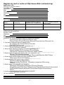
1
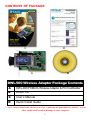
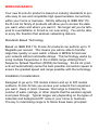
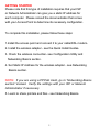
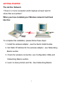
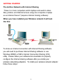
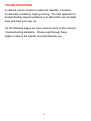
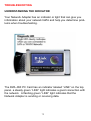
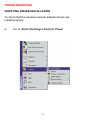
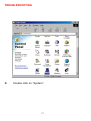
DWL-500 PCI Wireless Adapter User's Manual Table of Contents for the DWL-500 PCI Wireless Adapter Introduction i Contents of Package ii Wireless Basics 1 Getting Started 3 Configuration Utility 10 Troubleshooting 18 Networking Basics 38 Technical Support 65 Specifications 66 Warranty 70 Registration 75 INTRODUCTION The D-Link DWL-500 802.11b Wireless PCI Adapter is an ideal way to connect your laptop computer to a wireless network or as part of a wired LAN (Local Area Network) with a wireless network segment. After completing the steps outlined in this manual, you will have the ability to share information and resources - such as files and printers- and take full advantage of a “connected” environment for work and play! This DWL-500 comes with drivers for the most popular operating systems and can be integrated into a large network. The User’s Manual is designed to help you connect your laptop to a network when running Windows 98, Windows ME, NT 4.0 or 2000 in either Ad Hoc mode (without an Access Point) or Infrastructure mode (with an Access Point). Yet the IEEE802.11b standards compliance means this adapter gives you the flexibility to connect it to any 802.11b network. The IEEE 802.11b Ethernet standard allows you to connect computers and devices at speeds up to 11Mbps, depending on the distance between wireless adapters. This manual provides a quick introduction to wireless technology and its application as it relates to networking. Take a moment to read through this manual and familiarize yourself with wireless technology. But you should also give yourself some time to play with your new wireless network. i CONTENTS OF PACKAGE D C A B DWL-500 Wireless Adapter Package Contents A DWL-650 PCMCIA Wireless Adapter & PCI Cardholder* B Driver CD C User’s Manual D Quick Install Guide *Note: Please insert only the DWL-650 PC Card into the provided PCI Holder. Use of other cards could result in damage to your computer. ii WIRELESS BASICS Your new D-Link Air product is based on industry standards to provide easy to use and compatible high speed wireless connectivity within your home or business. Strictly adhering to IEEE 802.11b the D-Link Air family of products will allow you to access the data you want, when and where you want it. No longer will you be tethered to a workstation or forced to run new wiring. You will be able to enjoy the freedom that wireless networking delivers. Standards Based Technology Based on IEEE 802.11b, D-Link Air products can perform up to 11 Megabits per second. This means you will be able to transfer large files quickly or even watch a Movie in MPEG format over your network without noticeable delays. This technology works by using multiple frequencies in the 2.4GHz range utilizing Direct Sequence Spread Spectrum (DSSS) technology. D-Link Air products will automatically sense the best possible connection speed to ensure the greatest speed and range possible with the technology. Installation Considerations Designed to go up to 100 meters indoors and up to 300 meters outdoors, D-Link Air lets you access your network from anywhere you want. Keep in mind, however, that range is limited by the number of walls, ceilings, or other objects that the wireless signals must pass through. Typical ranges vary depending on the types of materials and background RF noise in your home or business. The key to maximizing range is to follow these basic principles: 1 WIRELESS BASICS 1. 2. 3. 4. 5. Keep the number of walls and ceilings to a minimum Each wall or ceiling can rob your D-Link Air Wireless product from 1-30M of range. Position your Access Points, Residential Gateways, and Computers so that the number of walls or ceilings is minimized. Be aware of the direct line between Access Points, Residential Gateways, and Computers A wall that is .5 meters thick, at a 45 degree angle appears to be almost 1 meter thick. At a 2 degree angle it looks over 14 meters thick! Try to make sure that the AP and Adapters are positioned so that the signal will travel straight through a wall or ceiling for better reception. Building Materials make a difference A solid metal door or aluminum studs may have a negative effect on range. Again, try to position Access Points, Residential Gateways, and Computers so that the signal passes through drywall or open doorways and not other materials. Make sure that the antenna is positioned for best reception by using the software signal strength tools included with your product. Keep your product away (at least 1-2 meters) from electrical devices that generate RF noise, like microwaves, Monitors, electric motors, etc. For the average American 4-bedroom home, range should not be a problem. If you experience low or no signal strength in areas of your home that you wish to access, consider positioning the Access Point in a location directly between the Residential Gateways and/or Computers that will be connected. Additional Access Points can be connected to provide better coverage in rooms where the signal does not appear as strong as desired. 2 GETTING STARTED To begin, you must select the type of wireless network you will be building and follow the relevant instructions. Which statement below best describes the type of network you want to build? The Home Internet Network with A Residential Gateway, Firewall, or Router(LAN administrators with Dynamic IPs should follow these instructions) "I have 2 or more computers and/or laptops and want to share files, printers, and Internet access using a Residential Gateway, Router, or Firewall or I want to connect to an Ethernet network that uses Dynamic (DHCP) IP addresses" (requires a Wireless Router or Access Point and Ethernet capable Gateway, Router, or Firewall or an existing Ethernet network). When you have installed your Wireless network it will look like this: OR 3 GETTING STARTED Please note that this type of installation requires that your Residential Gateway, Router, Firewall or Network Administrator can give you a dynamic IP address for each computer. Please consult the documentation that comes with your Access Point to determine its necessary configuration. To complete this installation, please follow these steps: 1.Using the provided Ethernet cable, connect the router to the Cable/DSLmodem. Also connect the Access Point to the Router. 2. Install the wireless adapter - see the Quick Install Guides. 3. Check the wireless connection- see Configuration Utility and Networking Basics section. 4. Check IP Address for the Wireless Adapter - see Networking Basics section NOTE: The default settings for the Wireless Adapter are set to obtain a Dynamic IP Address. 5. Learn to share printers and files - see Networking Basics section 4 GETTING STARTED The Home Internet Network with Multiple IPs (LAN administrators with Static IPs should follow these instructions) "I have 2 or more computers and/or laptops and want to share files, printers, and Internet access using multiple IP addresses that I have purchased from my Internet Service Provider or I want to connect to an Ethernet network that uses Static IP addresses" (requires Access Point, Ethernet capable Broadband modem, and multiple IP address Internet Account or an existing Ethernet network). When you have installed your wireless network it will look like this: 5 GETTING STARTED Please note that this type of installation requires that your ISP or Network Administrator can give you a static IP address for each computer. Please consult the documentation that comes with your Access Point to determine its necessary configuration. To complete this installation, please follow these steps: 1.Install the access point and connect it to your cable/DSL modem. 2. Install the wireless adapter - see the Quick Install Guides. 3. Check the wireless connection- see Configuration Utility and Networking Basics section. 4. Set Static IP Address for the wireless adapter - see Networking Basics section. NOTE: If you are using a PPPoE client, go to “Networking Basics section” instead. Verify the settings with your ISP or Network Administrator if necessary. 5. Learn to share printers and files - see Networking Basics. 6 GETTING STARTED The Ad Hoc Network "I have 2 or more computers and/or laptops and just want to share files and printers" When you have installed your Wireless network it will look like this: To complete this installation, please follow these steps: 1. Install the wireless adapter - see the Quick Install Guides. 2. Set Static IP Address for the wireless adapter - see Networking Basics section. 3. Check the wireless connection- see Configuration Utility and Networking Basics section. 4. Learn to share printers and file - See Networking Basics. 7 GETTING STARTED The Ad Hoc Network with Internet Sharing "I have 2 or more computers and/or laptops and want to share files, printers, and Internet access using one computer or laptop as an Internet Server" (requires Internet sharing software) When you have installed your Wireless network it will look like this: To share an Internet connection with Internet Sharing software you will need to purchase Internet Sharing software or use Windows 98SE's or ME's Internet Connection Sharing (ICS) utility. Please follow your software documentation to properly configure the Internet sharing software after you install your wireless networking adapters. To install your wireless network adapter follow these steps: 8 GETTING STARTED If the Internet Sharing Software will be installed on the same computer into which you are installing this wireless network adapter follow these steps: 1. Install the wireless adapter - see the Quick Install Guides. 2. Set Static IP Address for the wreless adapter - see Networking Basics section. 3. Check the wireless connection- see Configuration Utility and Networking Basics section. 4. Learn to share printers and file - See Networking Basics. 5. Install your Internet Sharing Software. If the Internet Sharing Software is installed on a different computer follow these steps: 1. Install the wireless adapter - see the Quick Install Guides. 2. Check IP Address for the wireless adapter - see Networking Basics section. NOTE: The default settings for the wireless adapter is set to obtain a Dynamic IP Address. 3. Check the wireless connection- see Configuration Utility and Networking Basics section. 4. Learn to share printers and file - See Networking Basics. 9 CONFIGURATION UTILITY D-Link Air adapter products use the "Configuration Utility" as the management software. The utility provides the user an easy interface to change any settings related to the wireless adapter. When the computer is started, the "Configuration Utility" starts automatically and the system tray icon is loaded in the toolbar. Clicking on the utility icon will start the Configuration Utility. Another way to start the Configuration Utility is to click on Start > Programs > DLink DWL-650 Control Utility > Configuration Utility. If the utility icon appears with a red "X" in the toolbar, then the utility did not install properly and will need to be reinstalled. Sometimes the icon will be red. This happens when the wireless adapter is set to a different channel or the communication mode is set incorrectly. Verify your settings, and check that you are in range. When the utility is started, the following screen will be displayed. Figure 1 - Configuration Utility with opened "Link Info" tab 10 CONFIGURATION UTILITY Link Info Tab State The field will display the current state of the wireless adapter. 1. Associated - means that the wireless adapter is connected to another wireless adapter or Access Point / Wireless Gateway Router. The MAC address of the wireless adapter or Access Point will be displayed in hex format i.e. BSS ID (Basic Service Set ID) = 00:40:05:AC:11:32. Networking is available when the wireless adapter is associated to an Access point or another wireless adapter. 2. Scanning - means that the node is searching for an available Access Point and trying to detect the SSID (Service Set ID) of an Access Point within range. NOTE: This field will also display an error message if for some reason the driver failed to initialize. Rescan Pressing the rescan button will cause the wireless adapter to look for a connection. When the wireless adapter is set to "Infrastructure" mode, the wireless adapter will scan all available channels continuously until it finds one or more Access Points with a matching SSID. At that point it will attempt to authenticate and associate with the Access Point. Ad Hoc When the wireless is set to "Ad Hoc" mode, the wireless adapter will scan for 5 seconds looking for an existing Ad Hoc network using the same SSID. If one is not found the driver will "Start" its own Ad Hoc network. Current Channel and Current Tx Rate Shows the selected channel and transmit rate that are currently used by the wireless adapter for an active connection. 11 CONFIGURATION UTILITY Throughput These two fields display the instantaneous wireless Receive and Transmit throughput displayed in bytes per second. These values are updated every two seconds. Link Quality The Link Quality bar graph is only active when the node is in Infrastructure Mode. The bar graph displays the quality of the link between the node and its Access Point. A label summarizes the quality of the link over the bar graph, which can take on one of the following values: "Not Applicable" "Poor" "Fair" "Good" "Excellent" The wireless adapter will start looking for a better Access Point if the Link Quality becomes "Poor". Link Quality is a measure of receive and transmit errors over the radio channel. Signal Strength The Signal Strength bar graph is only active when the node is in Infrastructure Mode. The bar graph displays normalized signal strength as reported by the radio, averaged over all frames over 100 bytes long that are received from the Access Point. Configuration Tab The Configuration Tab contains several fields where the operating parameters of the wireless can be viewed and changed. Changes to any of the parameters in the panel can be applied to the wireless adapter without the need to reboot the PC. 12 CONFIGURATION UTILITY Figure 3 -Configuration Utility with opened "CONFIGURATION" tab Restore Defaults Pressing this button restores each field in the panel to its default value. "Apply Changes" or "OK" button must be pressed before the default values are restored. Undo Changes Pressing this button reverts all fields in the panel back to the previously "saved" values. Apply Changes This button becomes active only when one of the fields has been modified. Pressing this button applies the changed settings and saves the settings to the registry. 13 CONFIGURATION UTILITY Mode The field allows selection from a list of supported Network "Modes." The supported modes displayed are the following: "802.11b Ad Hoc," " Ad Hoc," and "Infrastructure." The default setting for the "Configuration Utility" is "Infrastructure." 1. 802.11 Ad Hoc - This is the 802.11b peer-to-peer mode of operation. In "802.11b Ad Hoc" only one wireless "cell" is supported for each different SSID. All communication is done from client to client without the use of an Access Point. "802.11b Ad Hoc" networking uses the same SSID for the wireless adapters for establishing the network connection. 2. Ad Hoc - A "non-compliant" mode that will allow Prism2 (and only Prism2) adapters to communicate with one another without an Access Point regardless of the SSID assigned to the wireless adapters. 3. Infrastructure - This mode of operation requires the presence of an 802.11b Access Point. All communication is done though the Access Point which relays packets to other wireless clients as well as to nodes on a wired network. SSID (Service Set Identification) The field allows the user to set the identification by typing the name for a particular group of connected wireless adapters and Access Point. The SSID has the name "default" as the initial settings after the drivers are loaded. Tx Rate The transmission rate is set to "Fully Automatic" as the default setting. However, the setting has options for 1Mb, 2Mb, Auto 1 or 2Mb, 5.5 Mb, and 11Mb. For most applications, it is recommended to leave the setting at "Fully Automatic." 14 CONFIGURATION UTILITY PS Mode PS (Pseudo Set) mode is by default set to "Disabled". When the mode is set to AdHoc or "802.11b AdHoc", then the PS mode will need to be changed to "Enable." Channel There is not an option to change the channel setting when the "Infrastructure" mode is selected. However, the option for channel selection is available in AdHoc or "802.11b AdHoc" mode. Encryption tab Figure 4 - Configuration Utility with opened "Encryption" tab. If an additional measure of security is desired on the wireless network, WEP (Wired Equivalent Privacy) encryption can be enabled. WEP encrypts each frame transmitted from the wireless adapter using one of the keys entered in the "WEP Key Entry" field. 15 CONFIGURATION UTILITY The Access Point or wireless adapter will accept only encrypted frames that it can decrypt correctly. This will only happen if the receiver has the "WEP Key" used by the transmitter. When WEP Encryption is enabled, there are two options: 64-bit and 128- bit. NOTE: 64 bit WEP is the same as 40 bit WEP! The lower level of WEP encryption uses a 40 bit (10 character) “secret key” (set by the user), and a 24 bit “Initialization Vector” (not under user control). The panel allows the entry of four keys for 64-bit encryption and one set for 128-bit key encryption. Each key must consist of hex digits, which means that only digits 0-9 and letters A-F are valid entries. The Configuration Utility will not apply keys that are not entered correctly. Passphrase Alternatively, a "Passphrase" can be entered which is used as a "seed" to randomly generate the four keys. Using the "Passphrase" saves considerable time since the same keys must be entered into each node on the wireless network. Manual Entry: Key 1 - Key 4 These four fields can be used to manually enter the encryption keys. This may be necessary if you wish this node to match keys in a different vendor's product. These fields also display the keys when they are generated using a Pass-phrase. Default Tx Key The button updates the wireless adapter with the four keys entered in Key 1 through Key 4. Once the "Apply" button is selected, the keys are updated for the wireless adapter. Please note that the "Default Tx Key" is not an available option when 128 bit encryption is selected. 16 CONFIGURATION UTILITY Apply This button updates the settings for the wireless adapter with the four keys displayed in Key field. The keys are updated in the driver registry for permanent storage until another key is selected. About tab Figure 5 - Configuration Utility with opened "ABOUT" tab About tab shows the product version including the details of the Driver, Configuration Utility, and NIC firmware version. 17 TROUBLESHOOTING A network can be simple to install and maintain. However, occasionally something might go wrong. The best approach to troubleshooting network problems is to start at the very simplest level and work your way up. On the following pages we have covered many of the common troubleshooting situations. Please read through these pages or skip to the specific one that interests you. 18 TROUBLESHOOTING UNDERSTANDING THE INDICATOR Your Network Adapter has an indicator or light that can give you information about your network traffic and help you determine problems when troubleshooting. The DWL-650 PC Card has an indicator labeled “LINK” on the top panel. a steady green “LINK” light indicates a good connection with the network. A flashing green “LINK” light indicates that the Network Adapter is sending or receiving data. 19 TROUBLESHOOTING VERIFYING DRIVER INSTALLATION To check that the wireless network adapter drivers are loaded properly: A. Go to: Start>Settings>Control Panel 20 TROUBLESHOOTING B. Double click on “System”. 21 TROUBLESHOOTING C. D. E. F. Click on the “Device Manager” Tab Click on the + symbol in front of “Network Adapters” Highlight “D-Link DWL-650 11 Mbps WLAN Adapter” Click on “Properties” 22 TROUBLESHOOTING G. H. Check under “Device Status” to see if the DWL-650 is working properly Click on the “Resources” tab. 23 TROUBLESHOOTING I. Check under “Conflicting device list” to identify if there are any existing conflicts. J. If there is an existing IRQ conflict, please refer to the “How to Free an IRQ” section of “Troubleshooting.” 24 TROUBLESHOOTING CHECKING THE WIRELESS ADAPTER CONFIGURATION A. Go to: START>Programs>D-Link Air DWL-650 Utility>D-Link DWL-650Control Utility 25 TROUBLESHOOTING CHECKING THE WIRELESS ADAPTER CONFIGURATION cont. B. C. D. E. Select the “Configuration” Tab. Check that the SSID “name” is the same as that of the Access Point. Check that the Network mode is set properly to “Infrastructure” mode when there is an Access Point in the network. Otherwise, the mode should be set to “Ad Hoc.” To change any settings, click on the arrow for the drop down menu. Highlight the desired setting. Click on the “Apply Changes” box and click OK. 26 TROUBLESHOOTING CHECKING THE ACCESS POINT CONFIGURATION A. Go to: START>Programs>D-Link Wireless LAN> D-Link AP Manager B. Check that the “IP Address”, assigned to the Access Point is within the range assigned by the DHCP server. When using D-Link routers, the DHCP server will assign an IP range of 192.168.0.2 - 192.168.0.254 C. Check that the “Channel” setting for the Wireless Adapter is the same channel setting as that of the Access Point. D. Check that the “Network ID” matches the SSID name of the Wireless Adapter. E. Check that “Security” setting is the same for both the Wireless Adapter and the Access Point. 27 TROUBLESHOOTING CHECKING PCMCIA SOCKET CONTROLLER A. Go to: START>SETTINGS>CONTROL PANEL 28 TROUBLESHOOTING CHECKING PCMCIA SOCKET CONTROLLER cont. B. Double click on “System.” 29 TROUBLESHOOTING CHECKING PCMCIA SOCKET CONTROLLER continued C. D. E. F. Click on the “Device Manager” Tab. Click on the + symbol in front of “PCMCIA Socket.” Highlight “CardBus Controller.” Click on “Properties.” 30 TROUBLESHOOTING CHECKING PCMCIA SOCKET CONTROLLER continued G. H. I. Check under “Device Status” to see if the CardBus Controller is working properly. If the socket controller is not loading automatically, please contact the laptop manufacturer. Another option is to try loading the socket controller available within the OS or a socket controller provided by a third party software manufacturer. Click on the “Resources” tab. 31 TROUBLESHOOTING CHECKING PCMCIA SOCKET CONTROLLER continued J. K. Check under “Conflicting device list” to identify if there are any existing conflicts. If there is an existing IRQ conflict, please refer to the “How to Free an IRQ” section of “Troubleshooting.” 32 TROUBLESHOOTING HOW TO FREE AN IRQ What to do if you don’t have an available IRQ If there is not an available (open) IRQs on your system, you can do the following. The first thing you can do is let your Motherboard and Windows do the work for you. For this option you will need to check that you have a Plug and Play compatible Motherboard and set it to reset the configuration. Note: All of the setting names below may not be the exact wording on your system. This is due to the great number of Motherboard and hardware manufacturers. The settings may be listed on your system using different words that mean the same thing. Refer to your motherboard’s manual or contact the manufacturer if you are unsure. Perform the following steps to check for a Plug and Play Motherboard and to reset the configuration. 1. Reboot your computer. 2. When your computer is going through its POST (Power On Self Test) enter into your BIOS(Basic Input/Output System). 3. Some BIOS’s have a setting that will let you enable the Motherboard for Plug and Play. You should look for a setting that says “Plug and Play OS.” “Enable” this function. 4. The second setting to look for is under the heading “PNP/PCI Configuration.” Under this heading check to make sure that “Resources Controlled By” is set to “Auto.” 33 TROUBLESHOOTING HOW TO FREE AN IRQ What to do if you don’t have an available IRQ continued 5. The next setting below should be “Reset Configuration” or “Reset ESSCD”. Set this to “Enabled.” Note: This is a one-time setting. Meaning after you reboot your computer the setting will return to “Disabled.” This setting allows Windows to reconfigure all of the configuration information for your Plug and Play hardware. It is reset to “Disabled” so that Windows will not perform the reconfiguration each time you start your computer. 6. “Save” the new settings and Exit your BIOS. This will allow your computer to boot up and load Windows. 7. After Windows loads, check in the Device Manager to see if there is an available IRQ. 34 TROUBLESHOOTING HOW TO FREE AN IRQ If you do not have a Plug and Play Motherboard or you still do not have a free IRQ If you do not have a Plug and Play Motherboard or you still do not have a free IRQ you might need to disable some unused Hardware. For instance if you have a PS/2 or USB Mouse then you might be able to disable your COM Ports. Perform the following steps to disable your COM Ports. 1. Reboot your computer. 2. When your computer is going through its POST (Power On Self Test) enter into your BIOS (Basic Input/Output System). 3. Under the heading “Integrated Peripherals,” look for “Serial Port 1 or 2” or “COM Port 1 or 2.” 4. Change the setting to “Disable.” 5. Go to the heading “PNP/PCI Configuration.” 6. Make sure the setting for “Resources Controlled By” is set to “Auto.” 7. Change the setting for “Reset Configuration” to “Enabled.” 8. Hit the “ESC” key and go to the heading “Save and Exit.” 9. Let Windows load and follow the steps to Checking for an Availabler IRQ. 35 TROUBLESHOOTING HOW TO FREE AN IRQ If you do not have a Plug and Play Motherboard or you still do not have a free IRQ continued Other hardware that can be disabled Other hardware that can be disabled on your system might be what are referred to as “Built On.” If your Motherboard has a “Built On” Modem and you have upgraded your Modem you might want to see if it is disabled. Perform the following steps to disable a “Built On” Modem. 1. Reboot your computer. 2. When your computer is going through its POST (Power On Self Test) enter into your BIOS (Basic Input/Output System). 3. Under the heading “Integrated Peripherals,” look for a setting “Modem COM Port.” 4. Change the setting to “Disable.” Note: Only disable your “Built On” Modem if you know that you have upgraded your Modem, you have had a Broadband connection (Cable/DSL) installed, or if youdo not use it to connect to the Internet. Disabling the “Built On” Modem will make it so it no longer functions, until reset to “enabled.” 5. Go to the heading “PNP/PCI Configuration.” 6. Make sure the setting for “Resources Controlled By” is set to “Auto.” 36 TROUBLESHOOTING HOW TO FREE AN IRQ If you do not have a Plug and Play Motherboard or you still do not have a free IRQ continued 7. Change the setting for “Reset Configuration” to “Enabled.” 8. Hit the “ESC” key and go to the heading “Save and Exit.” 9. Let Windows load and follow the steps to Checking for an Available IRQ. Other ideas for freeing up IRQs If these steps do not free up an IRQ for you, you might need to remove some unused hardware from your system. The above steps can be followed to remove a “Built On” Sound Card as well. Another option for freeing up an IRQ is switching your Mouse either PS/2 or USB. This will free up the IRQs for your COM Ports and you should follow the above steps for disabling the COM Ports in your BIOS. Note: You might need to contact your computer manufacturer for more information on freeing up an IRQ on your specific system. 37 NETWORKING BASICS You may have had some ideas about how to use your new network prior to installing this kit - sharing files, printing from a computer on the network, or accessing the Internet on multiple computers with one connection. This section will help you get started on those ideas or even give you some new ones. However, this section is not intended to be a comprehensive guide to networking, it is just an outline of a few networking basics. If you are interested in learning more about networking, we have identified some Internet resources that may be of interest: D-Link Systems, Inc. http://www.dlink.com D-Link is one of the largest manufacturers of Ethernet products in the world. D-Link’s technological expertise and dedication to providing quality products at a low price makes D-Link a good place to watch for the newest in networking innovations. Or, you may want to get the newest drivers available for your Network Adapters. 38 NETWORKING BASICS Computer Identification If you had previously given your Windows 98 computers names or if you are using Windows 98, you may need to verify that each computer has a unique name and common workgroup name. A. On your Desktop, right-click the icon "Network Places" and select "Properties" from the context menu. B. Click the "Identification" tab on the top of the dialog box. 39 NETWORKING BASICS Computer Identification C. Type a unique, identifying name for this particular computer in the "Computer name:" box. This will be the name that other computers on your network will use to communicate with this computer. Each computer’s name must be unique on a particular network or confusion will result. (The computer’s name should be 15 or fewer characters with no spaces.) D.Type the workgroup name this computer will be a part of in the "Workgroup:" box. All of the computers on your network should have an identical Workgroup name. E. The "Computer Description:" box is optional. You may enter a description that will help you identify this computer on your network. Then click "Close." F. Repeat this process for each computer on your network to ensure that they all have a unique "Computer Name" and identical "Workgroup." 40 NETWORKING BASICS Sharing Files With your computers connected together on a network, you may now open and save files on another computer. You will be able to specify particular folders or disk drives to "share" and even password protect them. The steps below will enable you to share specific files and folders with other computers on your network. A. On your Desktop, right-click the icon "Network Places" and select "Properties" from the context menu. B. This dialog box is where you will come to configure most of your computers network settings. It is also available through the "Network" icon in the Control Panel. C. Click the "File and Print Sharing·" button. 41 NETWORKING BASICS Sharing Files D. Click to place a check mark next to "I want to be able to give others access to my files." E. Click "OK" on the "File and Print Sharing" dialog box. F. Click "OK" on the "Network" dialog box. G. Provide the Windows 98 installation CD or diskette(s) if prompted or direct Windows to the proper location of the installation files. Reboot if prompted. 42 NETWORKING BASICS Sharing Files H. You will now be able to identify a particular folder or disk drive to share. You may want to share a folder that both you and a colleague/family member needs to access occasionally. Or, maybe you want to share a CD-ROM drive so your other computer that does not have one can read CD’s. Both of these processes are the same. Only the disk drives and folders that you specifically identify as shared will be accessible to other computers on your network. I. Find the disk drive or folder you want to share with Windows Explorer or the "My Computer" icon on your desktop. J. Right-click on the disk drive or folder icon and select "Sharing." 43 NETWORKING BASICS Sharing Files K. Select "Share As:" to set the parameters for sharing this particular disk drive or folder. L. The "Share Name:" box is used to identify the disk drive or folder you are sharing to other computers on the network. You can give it any name you wish. However, a specific identification may help as more resources on your network are shared. M. The "Comment:" box is optional. You can use this box to further describe the disk drive or folder for others on the network. N. "Access Type:" allows you to designate how much someone else on the network can do with this disk drive or folder. "Read-Only" allow others to only look at or open the files on the disk drive or in the folder. "Full" allows others to read, write, open, save, copy, move, and delete files on the disk or in the folder. "Depends on Password" gives other computers access conditional upon the password they provide. 44 NETWORKING BASICS Sharing Files O. "Passwords:" allow you to apply a level of security to your shared disk drives and folders. Another computer (user) will be required to enter the password you designate here before accessing the disk drive or folder. Two passwords are used to give two levels of security (or access) to others on the network using the "Depends on Password" setting. Leaving the "Password" boxes empty gives everyone on the network access to the disk drive or folder. P. Click "OK" to continue. You will be prompted to enter the password(s) you provided for verification. Retype the password(s) just as you entered them the first time. 45 NETWORKING BASICS Sharing Files Q. You may now access this disk drive or folder from another computer on your network. Do so by double-clicking the "My Network Places" icon on your desktop or inside Windows Explorer. R. Navigate to the computer with the shared disk drive or folder (recognized by the "Computer Name" you provided), double-click. You should now see the disk drive or folder, double-click. If you specified a password when sharing this disk drive or folder, you will be prompted for the password. S. You can access a disk drive or folder shared over the network from most Windows applications. To make this process easier, Windows allows you to map these disk drives and folders to a drive letter on another computer. For example, on a computer where you are accessing a shared folder from another computer, inside Windows Explorer right-click and select "Map Network Drive·" You will then be able to assign an available drive letter. Checking "Reconnect at logon" allows Windows to map this network drive each time you start your computer. 46 NETWORKING BASICS Sharing Printers "Sharing" a printer connected to one computer with other computers on you network can be very convenient - allowing you to print from any computer on the network. The steps below will enable you to print with other computers on your network. A. On your Desktop, right-click the icon "Network Places" and select "Properties" from the context menu. 47 NETWORKING BASICS Sharing Printers B. Click the "File and Print Sharing·" button. C. Click to place a check mark next to "I want to be able to allow others to print to my printer(s)." D. Click "OK" on the "File and Print Sharing" dialog box. E. Click "OK" on the "Network" dialog box. 48 NETWORKING BASICS Sharing Printers F. You may now share any installed printers connected to this computer with other computers on your network. From the Start select Setting then select "Printers." Right click on the printer you want to share with others on the network and select "Sharing." G. Click "Share As:" and provide a "Share Name:" to identify the printer to other computers on the network. "Comment:" and "Password:" are optional. Then click "OK". For a computer to access a Network Printer, the device driver or software for that printer must be installed and pointed to the proper location of the printer. This is done much the same way you installed the printer on the computer it is connected to. H. Go to a computer that does not have the printer connected to it. From the "Start" button on the Task Bar select "Settings" and then "Printers". I. Double click the "Add Printer" icon. J. The "Add Printer Wizard" will appear. Click "Next." 49 NETWORKING BASICS Sharing Printers K. Choose "Network printer" and click "Next." L. Now you will identify the location of the Network Printer. If you know the name of the computer and the share name of the printer, you can type it into the "Network path or queue name:" box. However, it is easier to click the "Browse" button and navigate to the location of the printer. Click "OK" when you have selected the desired printer. Finish the installation by continuing the "Add Printer Wizard" normally. M. You may now use the Network Printer as if it was connected directly. Note: the computer that the printer is connected to must be on to use the printer. If you find this inconvenient, devices known as Network Print Servers are available from D-Link including the DP-301 and DP-101P. A Network Print Server would allow you to directly connect your printer to your network without worrying about which computer is 'on'. 50 NETWORKING BASICS How to Install TCP/IP Go to START > Settings > Control Panel Double click on “Network”. 51 NETWORKING BASICS How to Install TCP/IP Select the “D-Link DWL-650 Wireless Adapter” Click on “Add” Select “Protocol” Click “Add” 52 NETWORKING BASICS How to Install TCP/IP Select “Microsoft” Scroll down and Select “TCP/IP” Click “Ok” Now the “TCP/IP for D-Link DWL-650 Wireless Adapter” will be available. The TCP/IP Installation is now complete. 53 NETWORKING BASICS Configuring a Dynamic IP Address When the drivers are installed, the default setting is set to obtain IP dynamically through a DHCP server. If you need to check or change the settings, then do the following: Go to START > Settings > Control Panel Double Click on “Network” 54 NETWORKING BASICS Configuring a Dynamic IP Address Highlight TCP/IP for the DWL-650 Click on “Properties” NOTE: If TCP/IP is not present see Section 1: “How to Install TCP/IP”. 55 NETWORKING BASICS Configuring a Dynamic IP Address When the TCP/IP window opens, choose “IP Address” tab. Select “Obtain an IP Address Automatically” Click “OK” When the network properties window comes back up, click “OK”. Windows will ask you to reboot and click “Yes”. 56 NETWORKING BASICS Configuring a Static IP Address Go to START > Settings > Control Panel Double Click on “Network” 57 NETWORKING BASICS Configuring a Static IP Address Highlight TCP/IP for the DWL-650. Scroll down if you cannot see it Click on “Properties” NOTE: If TCP/IP is not present see Section 1: “How to Install TCP/IP”. 58 NETWORKING BASICS Configuring a Static IP Address When the “TCP/IP Properties” window opens, choose “IP Address” tab Select “Specify an IP address” Enter an IP address into the empty field. Suggested IP Range 192.168.0.2 to 192.168.0.254 NOTE: IP Addresses must be signed sequentially to each computer. Suggested Subnet Mask of 255.255.255.0 Click “OK”. When the “Network Properties” window comes back up click “OK”. Insert Windows CD if prompted. Windows will ask you to reboot and click “Yes”. 59 NETWORKING BASICS Checking TCP/IP Address of the wireless Adapter Click on the Start button and click "Run". Figure 11 - Start > Run 60 NETWORKING BASICS Checking TCP/IP Address of the Wireless Adapter Type "winipcfg" in the "Open" box. Click "OK". The IP Configuration screen will be displayed. The IP address will be displayed in the IP Address box. Click on "More Info" to display additional IP information. 61 NETWORKING BASICS Checking TCP/IP Address of the Wireless Adapter Additional IP information: 62 NETWORKING BASICS Checking the Connection by Pinging Click on the Start button and click "Run." Type "command" in the "Open" box. Click "OK" to get to a DOS prompt. 63 NETWORKING BASICS Checking the Connection by Pinging Type "ping 192.168.0.1", which is the IP address of the Gateway in this case, and hit the "Enter" key. A successful ping will show four replies. 64 CONTACTING TECHNICAL SUPPORT D-Link provides free technical support. North American customers can contact D-Link technical support through our web site, e-mail, or by phone. North American technical support is available Monday through Friday from 6:00 a.m. to 6:00 p.m. (PST). Web: http://www.dlink.com E-mail: [email protected] Phone: 949-788-0805 (option #4) Thank you for purchasing the D-Link DWL-500. We like to receive feedback from our customers concerning our products. Please take a moment to visit our web site. You can register your purchase on-line, learn more about the newest networking products, and let us know the things your new network has empowered you to do. 65 TECHNICAL SPECIFICATIONS Product Name: D-Link DWL-500 Model: DWL-500 Standards: IEEE 802.11b All major networking standards (including IP, IPX) Currently undergoing WiFi Certification · · · Adapter Type: PCI Local Bus 2.2 compliant · Transport Protocols: TCP/IP IPX/SPX NetBEUI NDIS3/4 · · · · TCP/IP Protocols: BOOTP DHCP Telnet FTP · · · · Supported OS: Windows 95 OSR 2 Windows 98 Windows ME Windows 2000 Windows NT 4 or newer · · · · · Data Security: 40 bit WEP (Wired Equivalent Privacy) Encryption · Data Rate: Mbps/channel 11 : CCK 5.5 : CCK 2 : DQPSK 1 : DBSK · · · · 66 Range: indoor - per cell approximately 35 to 100 meters outdoor - per cell approximately 100 to 300 meters · · Power Requirements: 250mA · Antenna: Internal diversity patch antenna · Transmit Power: Nominal Temp Range: 14 dBm max, 11 dBm min. Extend Temp Range: 13 dBm max, 10 dBm min. Transmit Power: 2.7V to 3.0V, 13 dBm max, 10 dBm min. · · · Frequency Range: 2.400 - 2.4835 GHz, Direct Sequence Spread Spectrum (DSSS) · Network Architecture: · · · · Supports Ad-Hoc Mode (Peer-to-Peer without Access Point) Supports Infrastructure Mode (Communications to wired networks via Access Points with Roaming) Compliant with IEEE 802.11b Standards Operating Channels: 1-11 United States (FCC) 1-11 Canada (DOC) 1-14 Japan (MKK) 1-13 Europe (Except Spain and France) (ETSI) · · · · 67 Physical Dimensions: L = 166 mm (w/Antenna extended) W = 18 mm H = 120 mm · · · Diagnostic LED (Green): Power Activity Link · · · Temperature: Operating Temperature: -10°C to 50°C Storing: -20°C to 70°C · · Humidity: Max. 95%, non-condensing · Emissions: FCC CE ETSI 300.328 ARIB-Telec · · · · Safety: UL · Warranty: Lifetime Warranty and Free Technical Support · Standards: IEEE 802.11b All major networking standards (including IP, IPX) Currently undergoing WiFi Certification Port: (1) RJ-45, 10Base-T (1) Power - 5V DC 1.5A (Center on Positive) · · · · · · 68 Copyright ©2000 D-Link, all rights reserved. D-Link, DWL-120, DWL-1000AP, DWL-500, and DWL-650 are registered trademarks of D-Link. Microsoft Windows 98, Windows ME, Windows 2000, and Windows NT are trademarks of the Microsoft Corporation. All other trademarks are registered trademarks or trademarks of their respective holders. All specifications are subject to change without notice. 69 LIMITED WARRANTY D-Link Systems, Inc. ("D-Link") provides this limited warranty for its product only to the person or entity who originally purchased the product from D-Link or its authorized reseller or distributor. Limited Hardware Warranty: D-Link warrants that the hardware portion of the D-Link products described below ("Hardware") will be free from material defects in workmanship and materials from the date of original retail purchase of the Hardware, for the period set forth below applicable to the product type ("Warranty Period") if the Hardware is used and serviced in accordance with applicable documentation; provided that a completed Registration Card is returned to an Authorized D-Link Service Office within ninety (90) days after the date of original retail purchase of the Hardware. If a completed Registration Card is not received by an authorized D-Link Service Office within such ninety (90) day period, then the Warranty Period shall be ninety (90) days from the date of purchase. Product Type Warranty Period Product (excluding power supplies and fans), if purchased and delivered in the fifty (50) United States, or the District of Columbia (“USA”) As long as the original purchaser still owns the product. Product purchased or delivered outside the USA One (1) Year Power Supplies and Fans One (1) Year Spare parts and spare kits Ninety (90) days D-Link's sole obligation shall be to repair or replace the defective Hardware at no charge to the original owner. Such repair or replacement will be rendered by D-Link at an Authorized D-Link Service Office. The replacement Hardware need not be new or of an identical make, model or part; D-Link may in its discretion may replace the defective Hardware (or any part thereof) with any reconditioned product that D-Link reasonably determines is substantially equivalent (or superior) in all material respects to the defective Hardware. The Warranty Period shall extend for an additional ninety (90) days after any repaired or replaced Hardware is delivered. If a material defect is incapable of correction, or if D-Link determines in its sole discretion that it is 70 not practical to repair or replace the defective Hardware, the price paid by the original purchaser for the defective Hardware will be refunded by D-Link upon return to D-Link of the defective Hardware. All Hardware (or part thereof) that is replaced by D-Link, or for which the purchase price is refunded, shall become the property of D-Link upon replacement or refund. Limited Software Warranty: D-Link warrants that the software portion of the product ("Software") will substantially conform to D-Link's then current functional specifications for the Software, as set forth in the applicable documentation, from the date of original delivery of the Software for a period of ninety (90) days ("Warranty Period"), if the Software is properly installed on approved hardware and operated as contemplated in its documentation. D-Link further warrants that, during the Warranty Period, the magnetic media on which D-Link delivers the Software will be free of physical defects. D-Link's sole obligation shall be to replace the non-conforming Software (or defective media) with software that substantially conforms to D-Link's functional specifications for the Software. Except as otherwise agreed by D-Link in writing, the replacement Software is provided only to the original licensee, and is subject to the terms and conditions of the license granted by DLink for the Software. The Warranty Period shall extend for an additional ninety (90) days after any replacement Software is delivered. If a material non-conformance is incapable of correction, or if D-Link determines in its sole discretion that it is not practical to replace the non-conforming Software, the price paid by the original licensee for the non-conforming Software will be refunded by D-Link; provided that the non-conforming Software (and all copies thereof) is first returned to D-Link. The license granted respecting any Software for which a refund is given automatically terminates. What You Must Do For Warranty Service: Registration Card. The Registration Card provided at the back of this manual must be completed and returned to an Authorized D-Link Service Office for each D-Link product within ninety (90) days after the product is purchased and/or licensed. The addresses/telephone/fax list of the nearest Authorized D-Link Service Office is provided in the back of this manual. FAILURE TO PROPERLY COMPLETE AND TIMELY RETURN THE REGISTRATION CARD MAY AFFECT THE WARRANTY FOR THIS PRODUCT. Submitting A Claim. Any claim under this limited warranty must be submitted in writing before the end of the Warranty Period to an Authorized D-Link Service Office. The claim must include a written description of the Hardware defect or Software nonconformance in sufficient detail to allow D-Link to confirm the same. The original product owner must obtain a Return Material Authorization (RMA) number from the Authorized D-Link Service Office and, if requested, provide written proof of purchase of the product (such as a copy of the dated purchase invoice for the product) before the warranty service is provided. After an RMA number is issued, the defective product must be packaged securely in the original or other suitable shipping package to ensure that it will not be damaged in transit, and the RMA number must be prominently marked on the outside of the package. The packaged product shall be insured and shipped to D-Link, 53 Discovery Drive, Irvine CA 92618, with all shipping costs prepaid. D-Link may reject or return any product that is not packaged and shipped in strict compliance with the foregoing requirements, or for which an RMA number is not visible from the outside of the package. The product owner agrees to pay D-Link's reasonable handling and return shipping charges for any product that is not packaged and shipped in accordance with the foregoing requirements, or that is determined by D-Link not to be defective or non-conforming. What Is Not Covered: This limited warranty provided by D-Link does not cover: 71 Products that have been subjected to abuse, accident, alteration, modification, tampering, negligence, misuse, faulty installation, lack of reasonable care, repair or service in any way that is not contemplated in the documentation for the product, or if the model or serial number has been altered, tampered with, defaced or removed; Initial installation, installation and removal of the product for repair, and shipping costs; Operational adjustments covered in the operating manual for the product, and normal maintenance; Damage that occurs in shipment, due to act of God, failures due to power surge, and cosmetic damage; and Any hardware, software, firmware or other products or services provided by anyone other than D-Link. Disclaimer of Other Warranties: EXCEPT FOR THE LIMITED WARRANTY SPECIFIED HEREIN, THE PRODUCT IS PROVIDED "AS-IS" WITHOUT ANY WARRANTY OF ANY KIND INCLUDING, WITHOUT LIMITATION, ANY WARRANTY OF MERCHANTABILITY, FITNESS FOR A PARTICULAR PURPOSE AND NON-INFRINGEMENT. IF ANY IMPLIED WARRANTY CANNOT BE DISCLAIMED IN ANY TERRITORY WHERE A PRODUCT IS SOLD, THE DURATION OF SUCH IMPLIED WARRANTY SHALL BE LIMITED TO NINETY (90) DAYS. EXCEPT AS EXPRESSLY COVERED UNDER THE LIMITED WARRANTY PROVIDED HEREIN, THE ENTIRE RISK AS TO THE QUALITY, SELECTION AND PERFORMANCE OF THE PRODUCT IS WITH THE PURCHASER OF THE PRODUCT. Limitation of Liability: TO THE MAXIMUM EXTENT PERMITTED BY LAW, D-LINK IS NOT LIABLE UNDER ANY CONTRACT, NEGLIGENCE, STRICT LIABILITY OR OTHER LEGAL OR EQUITABLE THEORY FOR ANY LOSS OF USE OF THE PRODUCT, INCONVENIENCE OR DAMAGES OF ANY CHARACTER, WHETHER DIRECT, SPECIAL, INCIDENTAL OR CONSEQUENTIAL (INCLUDING, BUT NOT LIMITED TO, DAMAGES FOR LOSS OF GOODWILL, WORK STOPPAGE, COMPUTER FAILURE OR MALFUNCTION, LOSS OF INFORMATION OR DATA CONTAINED IN, STORED ON, OR INTEGRATED WITH ANY PRODUCT RETURNED TO D-LINK FOR WARRANTY SERVICE) RESULTING FROM THE USE OF THE PRODUCT, RELATING TO WARRANTY SERVICE, OR ARISING OUT OF ANY BREACH OF THIS LIMITED WARRANTY, EVEN IF D-LINK HAS BEEN ADVISED OF THE POSSIBILITY OF SUCH DAMAGES. THE SOLE REMEDY FOR A BREACH OF THE FOREGOING LIMITED WARRANTY IS REPAIR, REPLACEMENT OR REFUND OF THE DEFECTIVE OR NON-CONFORMING PRODUCT. GOVERNING LAW: This Limited Warranty shall be governed by the laws of the state of California. Some states do not allow exclusion or limitation of incidental or consequential damages, or limitations on how long an implied warranty lasts, so the foregoing limitations and exclusions may not apply. This limited warranty provides specific legal rights and the product owner may also have other rights which vary from state to state. 72 Trademarks Copyright 1999 D-Link Corporation. Contents subject to change without prior notice. DLink is a registered trademark of D-Link Corporation/D-Link Systems, Inc. All other trademarks belong to their respective proprietors. Copyright Statement No part of this publication may be reproduced in any form or by any means or used to make any derivative such as translation, transformation, or adaptation without permission from DLink Corporation/D-Link Systems Inc., as stipulated by the United States Copyright Act of 1976. CE Mark Warning This is a Class B product. In a domestic environment, this product may cause radio interference, in which case the user may be required to take adequate measures Warnung! Dies ist in Produkt der Klasse B. Im Wohnbereich kann dieses Produkt Funkstoerungen verursachen. In diesem Fall kann vom Benutzer verlangt werden, angemessene Massnahmen zu ergreifen. Advertencia de Marca de la CE Este es un producto de Clase B. En un entorno doméstico, puede causar interferencias de radio, en cuyo case, puede requerirse al usuario para que adopte las medidas adecuadas. Attention! Ceci est un produit de classe B. Dans un environnement domestique, ce produit pourrait causer des interférences radio, auquel cas l`utilisateur devrait prendre les mesures adéquates. Attenzione! Il presente prodotto appartiene alla classe B. Se utilizzato in ambiente domestico il prodotto può causare interferenze radio, nel cui caso è possibile che l`utente debba assumere provvedimenti adeguati. FCC Warning This equipment has been tested and found to comply with the limits for a Class B digital device, pursuant to part 15 of the FCC Rules. These limits are designed to provide reasonable protection against harmful interference in a residential installation. This equipment generates, uses and can radiate radio frequency energy and, if not installed and used in accordance with the instructions, may cause harmful interference to radio communications. However, there is no guarantee that interference will not occur in a particular installation. If this equipment does cause harmful interference to radio or television reception, which can be determined by turning the equipment off 73 and on, the user is encouraged to try to correct the interference by one or more of the following measures: -Reorient or relocate the receiving antenna. -Increase the separation between the equipment and receiver. -Connect the equipment into an outlet on a circuit different from that to which the receiver is connected. -Consult the dealer or an experienced radio/ TV technician for help. VCCI Warning 74 Register by mail or online at http://www.dlink.com/sales/reg/ Registration Card Print, type or use block letters. Your name: Mr./Ms Organization: Dept. Your title at organization: Telephone: Fax: Organization's full address: Country: Date of purchase (Month/Day/Year): Product Product Serial No. Model *Product installed in type of computer (e.g., Compaq 485) *Product installed computer serial number *Applies to adapters only. Product was purchased from: Reseller's name: Telephone: Fax: Reseller's full address: Answers to the following questions help us to support your product: 1. Where and how will the product primarily be used? oHome oOffice oTravel oCompany BusinessoHome Business oPersonal Use 2. How many employees work at installation site? o1 employee o2-9 o10-49 o50-99 o100-499 o500-999 o1000 or more 3. What network protocol(s) does your organization use ? oTCP/IP oIPX/SPX oOthers_____________________________ 4. What network operating system(s) does your organization use ? oNovell NetWare oSCO Unix/Xenix oLinux oSolaris oWindows NT oWindows 2000 oWindows '98/ME oOthers_________________ 5. What network management program does your organization use ? oD-View oHP OpenView/Windows oHPOpenView/Unix oSunNet Manager oNovell NMSoNetView 6000 oOthers 6. What network medium/media does your organization use ? oFiber-optics oCAT5 UTP oOthers_________________ 7. What applications are used on your network? oDesktop publishing oSpreadsheet oWord processing oCAD/CAM oDatabase management oAccounting oOthers_____________________ 8. What category best describes your company? oAerospace oEngineering oEducation oFinance oHospital oLegal oInsurance/Real Estate oManufacturingoTransportation/Utilities/Communication oVARoRetail/Chainstore/Wholesale oGovernmentoSystem house/company oOther________________________________ 9. Would you recommend your D-Link product to a friend? oYes oNo oDon't know yet 10.Your comments ? 75 76