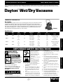
1
Operating Instructions and Parts Manual
3VE22, 4TB87A, 1UG91C and 2RPD8
Please read and save these instructions. Read carefully before attempting to assemble, install, operate or maintain the products described. Protect yourself and
others by observing all safety information. Failure to comply with instructions could result in personal injury and/or property damage! Retain instructions for future
reference.
Dayton Wet/Dry Vacuums
®
Commercial / Industrial Use
E
N
G
L
I
S
H
Description
The Dayton wet/dry vacuum cleaners are for vacuuming wet and dry non-combustible materials.
Equipped with powerful high-air flow, permanently lubricated, single-stage by-pass motors.
Features: motor housing, blower port, larger tank drains, long power cords, convenient on-board
tool storage and rugged dent resistant, rust proof plastic tanks. Equipped with easy roll casters
and large wheel dolly systems. Includes versatile deluxe accessory make-up (See Parts List).
Efficient filtration make-up (See Parts List). cULus Listed.
(1UG91C)
Specifications
Model
Tank
Style
Tank
Capacity
Peak
HP
Electrical
Rating
Static
Pressure
3VE22
Plastic
18
6.5
(68.1)
120V, 50/60 Hz
AC 12 Amps
4TB87A
Plastic
18
6.5
(68.1)
120V, 50/60 Hz
AC 12 Amps
1UG91C
Plastic
22
6.5
(83.3)
120V, 50/60 Hz
AC 12 Amps
2RPD8
32
(121)
120V, 50/60 Hz
AC 12 Amps
Plastic
6.5
Air Movement
60
(152.4)
200
(5.7)
60
(152.4)
195
(5.5) 60
(152.4)
210
(5.9)
60
(152.4)
210
(5.9)
Cartridge, Foam Sleeve
& Collection Bag
Cartridge & Foam Sleeve
Important safety instructions
ALWAYS WEAR
EYE PROTECTION
Never operate this unit when
flammable materials or
vapors are present because
electrical devices produce
arcs or sparks that can cause
a fire or explosion. NEVER
OPERATE UNATTENDED!
When using an electrical appliance,
basic precautions should always be
followed, including the following: Read all
instructions before using this
appliance.
To reduce the risk of fire, electrical
shock or injury:
1. Do not leave appliance when plugged in. Form 5S7252
Unplug from outlet when not in use and before servicing. Connect to a
properly grounded outlet
only. See Grounding
Instructions.
2. Do not expose to rain–store
indoors.
3. Do not allow to be used as a toy. Close attention is necessary when used by or near children.
4. Use only as described in this manual. Use
only Manufacturer’s recommended
attachments.
5. Do not use with damaged cord or plug. If
appliance is not working as it should, has
been dropped, damaged, left outdoors or
dropped into water, return it to a service
center.
6. Do not: pull or carry by cord, use cord as
a handle, close a door on cord or pull cord
around sharp edges or corners. Do not run
appliance over cord. Keep cord away from
Printed in U.S.A.
07985
Version 0
1/13
7. 8. 9. 10. 11.
12. 13.
14. 15. 16. Filters
E
S
Cartridge, Foam Sleeve
P
& Collection Bag
A
Cartridge
Ñ
& Foam Sleeve
O
L
heated surfaces.
Do not unplug by pulling on cord. To unplug,
grasp the plug, not the cord.
Do not handle plug or appliance with wet
hands.
Do not put any object into openings. Do
not use with any openings blocked; keep
free of dust, lint, hair and anything that may
reduce air flow.
Keep hair, loose clothing, fingers and all
parts of body away from openings and
moving parts.
Do not pick up anything that is burning or
smoking, such as cigarettes, matches or hot
ashes.
Do not use without dust bag and/or filters in
place.
Turn off all controls before unplugging.
Use extra care when cleaning on stairs.
Do not use to pick up flammable or
combustible liquids such as gasoline or use
in areas where they may be present.
Do not use your cleaner as a sprayer of
flammable liquids such as oil base paints,
87548-03
®
F
R
A
N
Ç
A
I
S
3VE22, 4TB87A, 1UG91C and 2RPD8
Dayton Operating Instructions and Parts Manual
Dayton Wet/Dry Vacuums
®
Important safety instructions (CONTINUED)
E
N
G
L
I
S
H
lacquers, household cleaners, etc.
17. Do not vacuum toxic, carcinogenic,
combustible or other hazardous materials
such as asbestos, arsenic, barium, beryllium,
lead, pesticides, or other health endangering
materials. Specially designed units are
available for these purposes.
18. Do not pick up soot, cement, plaster or
drywall dust without cartridge filter and
collection filter bag in place. These are very
fine particles that may pass through the foam
and affect the performance of the motor or
be exhausted back into the air. Additional
collection filter bags are available.
19. Do not leave the cord lying on the floor
once you have finished the cleaning job. It
can become a tripping hazard.
20. Use special care when emptying heavily
loaded tanks.
21. To avoid spontaneous combustion, empty
tank after each use.
22. The operation of a utility vac can result
in foreign objects being blown into eyes,
which can result in eye damage. Always
wear safety goggles when operating
vacuum.
23. STAY ALERT. Watch what you are doing
and use common sense. Do not use vacuum
cleaner when you are tired, distracted or
under the influence of drugs, alcohol, or
medication causing diminished control.
24. WARNING! Do NOT use this vacuum
cleaner to vacuum lead paint debris because
this may disperse fine lead particles into the
air. This vacuum cleaner is not intended for
use under EPA Regulation 40 CFR Part 745
for lead paint material cleanup.
SAVE THESE INSTRUCTIONS
Do not leave vacuum unattended when it is plugged in and/or operating. Unplug unit
when not in use.
grounding instructions
This appliance must be grounded. If it should
malfunction or breakdown, grounding provides
a path of least resistance for electric current to
reduce the risk of electric shock. This appliance
is equipped with a cord having an equipmentgrounding conductor and grounding plug.
The plug must be inserted into an appropriate
outlet that is properly installed and grounded in
accordance with all local codes and ordinances.
Improper connection
of the equipmentgrounding conductor
can result in a risk
of electric shock.
Check with a qualified
electrician or service person if
you are in doubt as to whether the
outlet is properly grounded. Do not
modify the plug provided with the
appliance—if it will not fit the outlet,
have a proper outlet installed by a
qualified electrician.
This appliance is for use on a nominal 120-volt
circuit, and has a grounded plug that looks like
the plug illustrated in sketch A.
A temporary adapter that looks like the adapter
illustrated in sketches B and C may be used
to connect this plug to a 2-pole receptacle as
shown in sketch B if a properly grounded
outlet is not available. The temporary adapter
should be used only until a properly grounded
outlet (sketch A) can be installed by a qualified
electrician. The green colored rigid ear, lug or
the like extending from the adapter must be
connected to a permanent ground such as a
properly grounded outlet box cover. Whenever
2
the adapter is used, it must be held in place by a
metal screw.
In Canada, the use of a temporary
adapter is not permitted by the
Canadian Electrical Code. Make sure that
the appliance is connected to an outlet having
the same configuration as the plug. No adapter
should be used with this appliance.
IF THE CORD IS DAMAGED, IT MUST
BE REPLACED BY A SPECIAL CORD
OR ASSEMBLY AVAILABLE FROM THE
MANUFACTURER OR HIS authorized
service agent.
Dayton Operating Instructions and Parts Manual
Models 3VE22, 4TB87A, 1UG91C and 2RPD8
EXTENSION CORDS
When using the appliance at a distance where an
extension cord becomes necessary, a 3-conductor
grounding cord of adequate size must be used
for safety and to prevent loss of power and
overheating. Use the table below to determine
A.W.G. wire size required. To determine ampere
rating of your vacuum, refer to nameplate located
on motor cover/housing. Before using appliance,
inspect power cord for loose or exposed wires and
damaged insulation. Make any needed repairs or
replacements before using your appliance. Use
Unpacking
1. Remove vacuum cleaner and all accessories from the carton.
2. Important: Open tank cover by pushing latches
or clamps outward with thumbs and remove
any accessories that may have been shipped in
the tank.
3. Assemble dolly or caster system following
instructions.
4. Before replacing cover, please refer to Dry Pick
Up or Wet Pick Up Operation to ensure proper
filter installation.
5. Replace cover and make sure latches or clamps
are secured over raised area of tank cover.
Assembly
a.
b.
only three-wire outdoor extension cords which
have three-prong grounding-type plugs and
three-pole receptacles which accept the extension
cord’s plug. When vacuuming liquids, be sure
the extension cord connection does not come in
contact with the liquid.
NOTE: Static shocks are possible
in dry areas or when the relative
humidity of the air is low. This is only
temporary and does not affect the
use of the vacuum cleaner. To reduce
that bottom is facing up.
2. With front of tank facing you, take caster feet
marked with the letter A (Figure 1) and place
in slots on left front and right rear of tank also
marked with the letter A (Figure 2). Secure
with screws provided (Figure 3).
3. Take caster feet marked with the letter B
(Figure 4) and place in slots on right front
and left rear of tank also marked with the letter
B (Figure 5). Secure with screws provided
(Figure 6).
4. If flat washers are included in hardware
package place flat washer over stem of caster
before installing casters into feet. NOTE: Flat
washers are not required with all units.
5. Insert casters into feet by placing stem of
caster into holes provided. Apply pressure and
twisting motion until casters snap into place
(Figure 7). Return tank to upright position.
1
2
A
A
A
c.
A
d.
A
A
3
4
B
B
e.
B
5
6
B
A
B
B
CASTER SYSTEM ASSEMBLY
On model 3VE22
You will find four caster feet (B), four casters (A)
and four screws with your wet/dry vacuum. Assemble as follows:
1. With cord disconnected from receptacle and
tank cover removed, turn tank upside down so
A
B
7
3
the frequency of static shocks in
your home, the best remedy is to add
moisture to the air with a console or
installed humidifier.
Volts
120V
Ampere Rating
More Not More
Than Than
0
6
10
12
-
6
10
12
16
Total length of cord in feet
100
150
25
50
AWG
18
18
16
14
16
16
16
12
16
14
14
14
12
12
Not recommended
Rear wheel/caster dolly/tool
holder and front caster feet
assembly
On models 4TB87A, 1UG91C and 2RPD8 two
casters (a.), two caster feet (b.), two wheels (c.),
one axle (e.), rear wheel dolly/tool holder (d.)
and four screws. Assemble as follows:
1. With cord disconnected from receptacle and
tank cover removed, turn tank upside down
so that the bottom is facing up.
NOTE: Model 2RPD8 has an adapter
between lid assembly and tank. This can be
removed for ease of use during caster dolly
assembly and to empty tank. Replace to
return to normal operation.
2. Place axle upright on a hard surface and
hammer on (1) cap nut. Place (1) wheel
on axle and slide down to cap nut (Figure
8). Be sure flat side of wheel hub is facing
outward.
3. Slide axle through holes provided in dolly/
basket (Figure 9).
4. Slide remaining wheel onto axle and hammer
on second cap nut (Figure 10).
5. Take rear wheel/caster dolly assembly and
place into slots (on rear of tank opposite
of drain) and secure with screws provided
(Figure 11).
6. Insert casters into the under side of rear
caster dolly pushing until casters snap into
place (Figure 12).
7. With tank drain facing you, take caster
foot marked with the letter A (Figure 13)
and place in slot on left side of tank also
marked with the letter A and secure with
screw provided (Figure 14). Insert caster, if
needed.
8. Take caster foot marked with the letter B
(Figure 15) and place in slot on right side of
tank also marked with the letter B and secure
with screw provided (Figure 16) Insert
caster, if needed.
9. Return tank to upright position.
®
E
N
G
L
I
S
H
3VE22, 4TB87A, 1UG91C and 2RPD8
Dayton Operating Instructions and Parts Manual
Dayton Wet/Dry Vacuums
®
Installation
Assembly (continued)
8
E
N
G
L
I
S
H
Installing the carriage
handle
On model 4TB87A, 1UG91C and
2RPD8 (Figure 20)
9
10
11
12
13
Stand vacuum right side up. Place metal carriage
handle outside of tank and under the side carrying
handles. Be sure to spread the ends of the carriage handles when assembling to prevent damage
to the tank. Align holes of carriage handle to holes
in tank and fasten tightly with screws, washers and
nuts provided. The sealing washer and screw have
a close fitting tolerance. Rubber side of sealing
washer should fit against inside wall of tank. Failure to properly install rubber washer could result in
water leakage or loss of performance. Replace the
tank cover and clamp the lid latches securely.
NOTE: For model 2RPD8, screws affix metal carriage handle to tank under bottom of side carry
handles.
A
14
15
A
B
A
16
TOOL HOLDER
(Not standard with all models)
1. With rear of unit facing you, take tool holder
and position it with tabs facing rear of unit
(Figure 17).
2. Place "J" shaped tabs into the slots on cord
wraps (Figure 18).
3. Press down until tabs snap into place.
4. Press down on center of tool holder until tab
latches on bottom of lid (Figure 19).
18
19
Model 2RPD8 features
21
a unique multi size inlet.
With inlet reducer in place,
vacuum tank can accept
standard and lock on 1.25”
to 2.5” diameter hose. With
inlet reducer removed,
vacuum tank can accept optional 3.5” diameter
hose (Figure 21).
Blower Feature
This vacuum can be used
22
as a powerful blower. To
use your unit as a blower,
unscrew blower port cover
located on the backside of
the motor housing (Figure
22). The blower port cover
is equipped with a retaining strap to prevent
loss of the port cover while blower is in use.
Insert hose end with locking-nut into blower
port of tank and tighten. For maximum blower
performance attach concentrator nozzle to
accessory end of hose. Caution should be used
when using a blower due to the powerful force of
air when using certain attachments.
B
A
17
NEVER OPERATE
UNATTENDED!
Figure 20
ALWAYS WEAR EYE PROTECTION TO
PREVENT ROCKS OR DEBRIS FROM BEING
BLOWN OR RICOCHETING INTO THE EYES
OR FACE WHICH CAN RESULT IN SERIOUS
INJURY.
Operation
This equipment incorporates
parts such as switches,
motors or the like that
tend to produce arcs or
sparks that can cause an
explosion. Do not pick up
flammable, combustible, or
hot materials. Do not use
around explosive liquids or
vapors, as electrical devices
produce arcs or sparks
which can cause a fire or explosion - do not
use at filling stations or anywhere gasoline is
stored or dispensed.
4
Always disconnect the plug from
the wall outlet before removing the
tank cover.
Keep Filters Clean
The efficiency of these vacuum cleaners is largely
dependent on the filter.
A clogged filter can cause overheating and
possibly damage the vacuum cleaner.
Clean or replace filters regularly. Do not use the
vacuum or filters for collecting hazardous or
other health endangering materials.
NOTE: Never machine wash or dry filters.
Dayton Operating Instructions and Parts Manual
Models 3VE22, 4TB87A, 1UG91C and 2RPD8
Operation (continued)
30
DRY PICK UP OPERATION
Make sure inlet deflector is fully inserted into
deflector guide on inside of tank. If it is not, install
inlet deflector by sliding it downward into slot on
deflector guide (Figure 23). NOTE: Hose must
be removed before inlet deflector can be inserted
into or removed from deflector guide. Opening on
inlet deflector can face either side of tank. Inlet
deflector should always be in place for any type of
cleaning. With the tank cover in an upside down
position, slide the cartridge filter down over the lid
cage, pushing until the filter seals against cover
(Figure 24).
NOTE: Foam sleeve does not need to be removed
for dry pick up. Place the filter retainer into the
top of the cartridge filter, holding the tank cover
with one hand, turn the handle on the filter
retainer clockwise to tighten, locking the filter into
place (Figures 25 & 26). To remove the filter
for cleaning, again hold the tank cover and turn
the filter retainer counter-clockwise to loosen
and remove, slide the cartridge filter off the lid
cage (Figures 27 & 28). To clean the cartridge
filter shake or brush off excess dirt or rinse (from
the inside of the filter) with water, dry completely
(approximately 24 hours) and re-install (Figures
29 & 30). Better quality filtration is required
for finer dry materials. Collection filter bags are
recommended for very fine materials such as dry
wall dust.
Note: When using the vacuum to pick up very
fine dust such as sawdust or dry wall dust, it
will be necessary to empty the tank and clean
the filter at more frequent intervals to maintain
maximum pick up power or upgrade to collection
filter bags.
23
29
INSTALLING COLLECTION FILTER
BAG
(Not standard on all models)
1. Use for dry pick up only. Use in conjunction
with cartridge filter for picking up soot,
cement, plaster or drywall dust.
2. With cord disconnected from receptacle, pull
latches in an outward motion and remove
tank cover.
3. Unscrew hose locking-nut and remove hose
from inlet (Figure 31).
4. Remove inlet deflector from deflector guide
(Figure 32).
NOTE: Hose must be removed before inlet
deflector can be taken out.
5. With the opening of the inlet deflector facing
the left or right side of the filter bag, slide
filter bag collar over deflector matching
notches of bag collar to tabs on inlet
deflector, bag will only fit properly one way
(Figure 33).
6. Slide deflector with collection bag attached
into deflector guide (Figure 34).
7. Reinsert hose into inlet and tighten lockingnut (Figure 35).
8. When secured in place, expand bag and
position around the inside of the tank.
31
32
24
33
25
34
26
35
27
28
NOTE: When removing filter bag from tank,
remove inlet deflector from filter bag collar and
reinstall into deflector guide. Inlet deflector should
always be in place for any type of cleaning.
AUTOMATIC SUCTION SHUT-OFF
This vacuum is equipped with an automatic
suction shut-off that operates when picking
up liquids. As the level of the liquid rises in the
tank, an internal float rises until it seats itself
against a seal at the intake of the motor, shutting
off suction. When this happens, the motor will
develop a higher than normal pitch noise and the
suction is drastically reduced. If this occurs, turn
the unit off immediately. Failure to turn unit off
after float rises and shuts off suction will result in
extensive damage to the motor. To continue use,
empty the liquid waste from the tank as outlined
in the paragraph below. (Emptying Tank).
NOTE: If accidentally tipped over, the vacuum
could lose suction. If this occurs, turn unit off
and place vac in upright position. This will allow
the float to return to its normal position, and you
will be able to continue operation.
Emptying Tank
Use special care when emptying heavily loaded
tanks. Your Wet/Dry Vacuum may be emptied of
liquid waste by removing the tank cover. To empty,
switch off the vac and remove the plug from
the wall receptacle. Remove the tank cover and
empty the tank.
Note: Model 2RPD8 has an adapter between lid
assembly and tank. This can be removed for ease
of use during caster dolly assembly and to empty
tank. Replace to return to normal operation.
Note: For those models with a tank drain, tank
can be emptied by removing drain cap and drain.
WET PICK UP OPERATION
Remove all dry filters plus
36
all dirt and debris found in
the tank assembly. For best
results for wet pick up we
recommend removing the
cartridge filter and utilizing
the foam sleeve (already in
place over lid cage). Make sure inlet deflector
is fully inserted into deflector guide on inside of
tank. If it is not, install inlet deflector by sliding it
downward into slot on deflector guide (Figure
36). NOTE: Hose must be removed before inlet
deflector can be inserted into or removed from
deflector guide. Opening on inlet deflector can
face either side of tank. Inlet deflector should
always be in place for any type of cleaning.
Misting in exhaust air may occur if the foam
sleeve becomes saturated during wet pick up.
If misting occurs, remove and dry the saturated
foam sleeve or replace with another dry foam
sleeve to eliminate the misting and possible
dripping of liquid around the lid. Turn the unit off
®
5
E
N
G
L
I
S
H
3VE22, 4TB87A, 1UG91C and 2RPD8
Dayton Operating Instructions and Parts Manual
Dayton Wet/Dry Vacuums
®
Operation (continued)
E
N
G
L
I
S
H
immediately upon completing a wet pick up job or
when tank is full and ready to be emptied, raise
the hose to drain any excess liquid into the tank.
The interior of the tank should be periodically
cleaned. The foam sleeve should be cleaned
periodically as described in the following steps:
1. Always disconnect the plug from the wall
receptacle before removing the tank cover.
Remove foam sleeve by sliding it up and off
the lid cage.
2. Shake excess dust off sleeve with rapid up
and down movement.
3. Hold sleeve under running water rinsing
from the inside. A water wash is not always
required, depending on the condition of the
sleeve.
4. Gently wring out excess water, blot sleeve
with a clean towel and allow foam sleeve
to dry. The foam sleeve is now ready to be
re-installed on the lid cage.
Note: Bottom of sleeve should be TUCKED
in groove between lid cage and tank lid
(Figure 37).
NOTE: Wet pick up accessories should be
washed periodically with soap and water,
especially after picking up wet, sticky liquids.
Picking up detergent or cleaners that create foam
or suds can defeat the vacuums filtration. This
could cause foreign material
37
to pass into the motor
impeller area and shorten
motor life. This is not normal
use and is not covered by
product warranty.
WET PICK UP AND
PUMP ASSEMBLY OPERATION (For
model 4TB87A only)
TO REDUCE THE RISK OF ELECTRICAL
SHOCK, DO NOT DIRECT DISCHARGE
STREAM AT UNIT!
1. Always disconnect the plug from the wall
receptacle before removing the tank cover.
2. Remove tank cover and cartridge filter. Tank
should also be cleaned of any dirt or debris.
3. Ensure that the foam sleeve is in
place for wet pick up. (See Wet Pick Up
Operation)
4. Make sure inlet deflector is fully inserted into
deflector guide on inside of tank.
5. Insert tube provided into pick up cage pushing
until tube comes to a stop (Figure 38).
6. Take pick up assembly and insert tube into
hole in bottom of lid cage pushing until
assembly comes to a stop (Figure 39).
NOTE: Do not attempt to pump without pick
up cage in place or screen on pick up cage.
Failure to do this could result in damage to
pump.
7. Replace tank cover and secure lid latches.
8. To prevent unwanted discharge of water leave
cap in place or attach garden hose to unit
until you are ready to empty tank.
9. Once you are ready to begin pumping, remove
outlet fitting cover and connect a standard
garden hose (not supplied) to outlet fitting
(Figure 40).
10. Attach the 2½" hose to tank inlet.
11.Your vacuum is supplied with a wet pick up
elbow. Place the elbow on the hose end and
attach desired accessory to elbow (Figure
41). Elbow MUST be in place during wet
pick up to prevent overfilling of unit. Do not
attempt wet pick up without elbow in place.
Do not cover bleed hole in elbow. Failure
to follow these precautions will result in
overfilling of unit and misting through exhaust
port.
THE CARTRIDGE FILTER IS NOT COMPATIBLE
WHEN UTILIZING THE PUMP PICK UP
ASSEMBLY.
12.Plug vacuum in and push the ON switch.
13. Start wet pick up. In order to prime the pump
feature, you will need at least 4" of water in
the bottom of the tank. At this time the unit
will automatically begin pumping. The unit will
automatically shut off when full.
14. To empty a full tank by pumping, first remove
the vacuum hose from the liquid. Do not
empty liquid from hose back into tank. This
will cause the unit to overfill and misting will
occur through the exhaust port.
15.The ON switch must be manually held in
the ON position for approximately 10-15
seconds to allow the water level to be reduced
sufficiently, and then pumping will continue
automatically. The unit will continue to
discharge liquid until there is about 4" left in
the tank.
NOTE: Wet pick up volume is greater than
the discharge volume and step 15 may need
to be repeated if the
unit should shut off.
16.After wet pick up and pumping has been
completed, the remaining liquid should be
emptied from the tank and the pump pick up
assembly should be removed and cleaned.
17.To utilize your vacuum as non-pump, refer to
dry pick up operation for proper installation of
filters.
38
39
40
41
Portable Blower Operation (For
model 3VE22 only)
BLOWER SAFETY
1.Never operate the portable blower in wet or
damp conditions. Do not use in rain.
2. Keep area of operation clear of all persons,
particularly small children and pets.
3. Dress properly. Do not wear loose clothing
or jewelry. Always wear substantial footwear
and long pants. Secure loose hair with a
hat or hair net to avoid hair being caught in
moving parts.
4. Never blow debris in direction of bystanders.
5. Do not overreach or use blower from
unstable surface such as ladders, trees, steep
slopes, roof tops, etc. Always be sure of your
footing.
6. Inspect the area before using the blower.
Remove all debris and hard objects such as
rocks, glass, wire, etc. that can be blown or
cause damage during operation.
7. Always wear a respirator or face mask when
working in dusty environments.
8. Keep vents clean and clear of dirt and debris.
BLOWER ASSEMBLY
INSTRUCTIONS
1. To remove portable
42
blower from tank cover,
grasp both blower
handles and pull in an
upward motion
(Figure 42).
2. Insert 2½” extension
wand into the blower exhaust. Push firmly
into place by twisting wand slightly.
3. Attach desired accessory (Figure 43).
43
4. Plug the cord into an electrical outlet. Your
portable blower is ready for use. NOTE: If an
6
Dayton Operating Instructions and Parts Manual
Models 3VE22, 4TB87A, 1UG91C and 2RPD8
Operation (continued)
44
47
48
Operating
Position
Dry
extension cord is used, use only an approved
outdoor extension cord. To prevent extension
cord from pulling away from appliance cord,
tie cords as shown (Figure 44).
5. To clean inlet shield and foam pad,
disconnect cord from receptacle and remove
screws on bottom side of power unit
(Figure 45)
6.Once removed, run foam pad under running
water and blot with a clean towel to dry.
7. After cleaning, replace inlet shield and foam
pad and secure with screws (Figure 46).
NOTE: Inlet shield will only fit properly one
way.
Always WEAR EYE PROTECTION TO
PREVENT ROCKS OR DEBRIS FROM BEING
BLOWn OR RICOCHETING INTO THE EYES
OR FACE WHICH CAN RESULT IN SERIOUS
INJURY.
45
46
Be sure to disconnect power supply
before attempting to service or
remove any components.
Before storing the vacuum cleaner, always empty
and clean the tank. Never allow liquids to sit in
the tank for any extended period of time.
14" Wet/Dry Floor
Nozzle
Lubrication
Service
Do not attempt to service your Dayton wet/dry
vacuum cleaner beyond that described in this
manual. Refer all other servicing to a qualified
service center.
Always store the vacuum cleaner indoors.
If any of the motor
housing parts should
become detached or
broken, exposing the
motor or any other
electrical components,
operation should be discontinued
immediately to avoid personal injury
or further damage to the vacuum.
Repairs should be made before
reusing the vacuum.
BLOWER OPERATION
1. The correct operating position is to hold
the portable blower in either hand, at arms
length at your side. Your portable blower has
been designed with the necessary angle to
direct the air blast toward the ground in front
of you (Figure 47).
2. Always work going away from solid objects
such as walls, large stones, automobiles and
fences.
3. Clean spaces with corners by starting in
corners and moving outward to open areas
to prevent an accumulation of debris which
could fly into your face.
4. Be careful when working near valuable
plants. The force of the air could damage
tender plants.
5. Use both handles when working above the
waist or when two-handed grip is desired.
6. Reattach portable blower for wet/dry
operation by placing power unit back into
tank cover pushing in a downward motion
until portable blower snaps into place
(Figure 48).
Wet
No lubrication is necessary as the motor is
equipped with lifetime lubricated bearings.
STORAGE
Do not operate blower without inlet
shield and foam pad in place.
E
N
G
L
I
S
H
Cord Wrap
Hose Holder
(Not standard with all models)
®
7
3VE22, 4TB87A, 1UG91C and 2RPD8
Dayton Operating Instructions and Parts Manual
Dayton Wet/Dry Vacuums
®
Troubleshooting Chart
E
N
G
L
I
S
H
Symptom Possible Cause(s) Corrective Action
Parts/accessories missing
Packed in tank Check in tank
Vacuum cleaner
will not start
1. Defective switch
2. Defective motor
1. Replace
2. Replace
Dust discharging
1. Filter not installed/not
from exhaust installed properly
2. Filter damaged
3. Filter clogged or dust is too fine
4. Filter not functional
1. Properly install filter
Loss of suction
1. Tighten hose connection
2. Clean or replace filter
3. Empty tank
4. Replace hose
1. Loose hose connection
2. Filter clogged
3. Full tank
4. Hole in hose
2. Replace filter
3. Use more efficient filter
4. Clean or replace filter
Limited Warranty
Dayton One-Year Limited Warranty. DAYTON MODELS COVERED IN THIS MANUAL ARE WARRANTED BY DAYTON ELECTRIC MFG. CO.
(DAYTON) TO THE ORIGINAL USER AGAINST DEFECTS IN WORKMANSHIP OR MATERIALS UNDER NORMAL USE FOR ONE YEAR AFTER DATE OF
PURCHASE. ANY PART WHICH IS DETERMINED TO BE DEFECTIVE IN MATERIAL OR WORKMANSHIP AND RETURNED TO AN AUTHORIZED SERVICE
LOCATION, AS DAYTON DESIGNATES, SHIPPING COSTS PREPAID, WILL BE, AS THE EXCLUSIVE REMEDY, REPAIRED OR REPLACED AT DAYTON’S
OPTION. FOR LIMITED WARRANTY CLAIM PROCEDURES, SEE “PROMPT DISPOSITION” BELOW. THIS LIMITED WARRANTY GIVES PURCHASERS
SPECIFIC LEGAL RIGHTS WHICH VARY FROM JURISDICTION TO JURISDICTION.
®
Limitation of Liability. TO THE EXTENT ALLOWABLE UNDER APPLICABLE LAW, DAYTON’S LIABILITY FOR CONSEQUENTIAL AND INCIDENTAL
DAMAGES IS EXPRESSLY DISCLAIMED. DAYTON’S LIABILITY IN ALL EVENTS IS LIMITED TO AND SHALL NOT EXCEED THE PURCHASE PRICE PAID.
Warranty Disclaimer. A DILIGENT EFFORT HAS BEEN MADE TO PROVIDE PRODUCT INFORMATION AND ILLUSTRATE THE PRODUCTS IN THIS
LITERATURE ACCURATELY; HOWEVER, SUCH INFORMATION AND ILLUSTRATIONS ARE FOR THE SOLE PURPOSE OF IDENTIFICATION, AND DO NOT
EXPRESS OR IMPLY A WARRANTY THAT THE PRODUCTS ARE MERCHANTABLE, OR FIT FOR A PARTICULAR PURPOSE, OR THAT THE PRODUCTS WILL
NECESSARILY CONFORM TO THE ILLUSTRATIONS OR DESCRIPTIONS. EXCEPT AS PROVIDED BELOW, NO WARRANTY OR AFFIRMATION OF FACT,
EXPRESSED OR IMPLIED, OTHER THAN AS STATED IN THE “LIMITED WARRANTY” ABOVE IS MADE OR AUTHORIZED BY DAYTON.
Technical Advice and Recommendations, Disclaimer. Notwithstanding any past practice or dealings or trade custom, sales shall not include the furnishing
of technical advice or assistance or system design. Dayton assumes no obligations or liability on account of any unauthorized recommendations, opinions or
advice as to the choice, installation or use of products.
Product Suitability. Many jurisdictions have codes and regulations governing sales, construction, installation, and/or use of products for certain purposes,
which may vary from those in neighboring areas. While attempts are made to assure that Dayton products comply with such codes, Dayton cannot guarantee
compliance, and cannot be responsible for how the product is installed or used. Before purchase and use of a product, review the product applications, and all
applicable national and local codes and regulations, and be sure that the product, installation, and use will comply with them.
Certain aspects of disclaimers are not applicable to consumer products; e.g., (a) some jurisdictions do not allow the exclusion or limitation of incidental or
consequential damages, so the above limitation or exclusion may not apply to you; (b) also, some jurisdictions do not allow a limitation on how long an implied
warranty lasts, consequently the above limitation may not apply to you; and (c) by law, during the period of this Limited Warranty, any implied warranties
of implied merchantability or fitness for a particular purpose applicable to consumer products purchased by consumers, may not be excluded or otherwise
disclaimed.
Prompt Disposition. A good faith effort will be made for prompt correction or other adjustment with respect to any product which proves to be defective
within limited warranty. For any product believed to be defective within limited warranty, first write or call dealer from whom the product was purchased. Dealer
will give additional directions. If unable to resolve satisfactorily, write to Dayton at address below, giving dealer’s name, address, date, and number of dealer’s
invoice, and describing the nature of the defect. Title and risk of loss pass to buyer on delivery to common carrier. If product was damaged in transit to you, file
claim with carrier.
Manufactured for Dayton Electric Mfg. Co., 100 Grainger Parkway, Lake Forest, Illinois 60045-5201 U.S.A.
8
1UG91C and 2RPD8
Dayton Operating Instructions and Parts Manual
For Repair Parts, call 1-800-323-0620
24 hours a day – 365 days a year
Please provide following information:
-Model number
-Serial number
-Part description and number as shown in parts list
Repair Parts List
Ref. #
Description
1
Handle
2
Switch Button - I
3
Switch Button - O
4
Motor Cover Assembly (incl. 1,2,3)
5
Screw 10 x ¾ Trilobe Twin Lead
6
= Power Unit Assembly (1UG91C)
(2RPD8)
7
Float
8
Lid Latch
9
Lid Cage and Latch Assembly (1UG91C)
(2RPD8)
10 Foam Sleeve
11
Cartridge Filter
12
Filter Retainer
13
Collection Filter Bag (1UG91C)
14
Inlet Deflector
15
Tank Assembly (1UG91C)
(2RPD8)
16
Drain Cover
17
Front Caster Foot A
18
Front Caster Foot B
19
Flatwasher (1UG91C)
20
Screw 10 x ¾ SL Hex Head
21
Caster (1UG91C)
(2RPD8)
22
Carriage Handle (1UG91C)
(2RPD8)
23
Screw ¼” - 20 x ¾” Slotted Thread (1UG91C)
24
Sealing Washer (1UG91C)
25
¼” - 20 Locknut - Heavy Hex HD (1UG91C)
26
Rear Dolly/Basket 27
Axle (1UG91C)
(2RPD8)
28
Rear Wheel, 8” (20.32cm) (1UG91C)
10” (25.4cm) (2RPD8)
29
Cap Nut
30
Spacer (2RPD8)
31
Adapter 22”-16” (55.3cm x 40.6cm) (2RPD8)
32
Handle, tank latch (2RPD8)
33
Hinge, tank latch (2RPD8)
34
Screw Lg slot washer Hd (2RPD8)
35
Deflector (2RPD8)
36
Tank inlet 3.5” (8.9cm) (2RPD8)
37
Screw #10 Trilobe (2RPD8)
38
Inlet reducer 3.5”-2.5” (8.9cm-6.4cm) (2RPD8)
∆
8 ft. x 2½" Hose (2.4m x 6.35cm)
∆
2½" (6.35cm) dia. Extension Wands
∆
14" (35.5cm) Wet/Dry Floor Nozzle
∆
8" (20.32cm) Utility Nozzle
∆
Crevice Tool
∆
Concentrator Nozzle
∆
Elbow Grip
∆
Hose Holder
(=)
2
3
Part No.
1
Qty
3751001
7414200
7414210
3743043
1517699
1UND3
8135597
3545000
7444500
1945065
1945067
5X879A
2W435
3008000
1UG85
7413120
7365697
1099897
7446800
7431320
7431370
0704399
1503999
6773900
6775200
2088000
8833800
0810899
0701299
1304599
7417350
2442100
2442700
2425010
2421000
4300299
1101999
8831600
8832300
8832200
1512199
8832000
8832100
1517799
8831900
2Z212B
0150400
0213696
5281500
0160400
0890401
0223000
3132630
1
1
1
1
12
1
1
1
2
1
1
1
1
1
1
1
1
1
1
1
1
2
4
2
2
1
1
4
4
4
1
1
1
2
2
2
2
1
4
4
4
1
1
4
1
1
2
1
1
1
1
1
1
4
5
E
N
G
L
I
S
H
6
7
8
9
11
5
13
12
10
14
22
25
24
15
23
16
26
18
19
21
20
30
27
28
29
17
31
22
33
32
34
36
38
35
37
15
Replacement parts not available for power unit.
∆Not Shown
16
Do not attempt to service your Dayton vacuum beyond that described in the Operating Instructions
and Parts Manual. These models have no user serviceable parts.
2RPD8
®
9
3VE22
Dayton Operating Instructions and Parts Manual
For Repair Parts, call 1-800-323-0620
24 hours a day – 365 days a year
Please provide following information:
-Model number
-Serial number
-Part description and number as shown in parts list
Repair Parts List
Ref. #
E
N
G
L
I
S
H
1
2
3
4
5
6
7
8
9
10
11
12
13
14
15
16
17
18
19
20
21
22
23
24
25
∆
∆
∆
∆
∆
∆
∆
∆
Description
Part No.
Qty
Switch Button - I
Switch Button - O
= Power Unit (includes items 1-6+25)
Intake Screen
Inlet Shield
Ferrule
Screw 10 x 3/4 Trilobe Twin Lead
Tank Cover
Float
Lid Latch
Lid Cage & Latch Assembly
Foam Sleeve
Cartridge Filter
Filter Retainer
Tank Assembly
Inlet Deflector
Collection Filter Bag
Tool Holder
Casterfoot A
Casterfoot B
Flatwasher
Caster
Screw 10 x 3/4 SL Hex Head
Drain Cover
Screw #10 Trilobe THD Roll 48
7414200
7414210
1UNE1
8541205
7442301
7350400
1517699
1944160
7411200
7444500
7350630
5X879A
2W435
3008000
7363497
7413120
1UG85
8411300
7431320
7431370
0704399
6773900
1503999
7446800
1517799
1
1
1
1
1
1
5
1
1
2
1
1
1
1
1
1
1
1
2
2
4
4
4
1
5
8 ft. x 2½" Hose (2.4m x 6.35cm)
2½" (6.35cm) dia. Extension Wands
14" (35.5cm) Wet/Dry Floor Nozzle
8" (20.32cm) Utility Nozzle
Crevice Tool
Concentrator Nozzle
Elbow Grip
Hose Holder
2Z212B
0150400
0213696
5281500
0160400
0890401
0223000
3132630
1
2
1
1
1
1
1
1
2
1
3
6
4
25
5
25
8
10
9
11
7
12
17
13
14
16
(=) Replacement parts not available for power unit.
∆ Not Shown
Do not attempt to service your Dayton vacuum beyond that
described in the Operating Instructions and Parts Manual.
These models have no user serviceable parts.
18
15
24
19
20
22
21
10
20
23
19
4TB87A
Dayton Operating Instructions and Parts Manual
For Repair Parts, call 1-800-323-0620
24 hours a day – 365 days a year
Please provide following information:
-Model number
-Serial number
-Part description and number as shown in parts list
Repair Parts List
Ref. #
Description
1
Handle
2
Switch Button - I
3
Switch Button - O
4
Motor Cover (Incls 1)
5
Screw 10 x ¾ Trilobe Twin Lead
6 =Power Unit Assembly
7
Lid Latch
8Outlet Fitting Cap
9
Foam Sleeve
10
Cartridge Filter
11
Filter Retainer
12
Pickup Tube
13
Pickup Cage Assembly
14
Tank Assembly
15
Inlet Deflector
16
Drain Cover
17
Carriage Handle
18
Screw ¼” - 20 x ¾” Slotted Thread
19
Sealing Washer
20
¼” - 20 Locknut-Heavy Hex Hd
21
Casterfoot A
22
Casterfoot B
23Flatwasher
24Caster
25
Screw 10 x ¾” Hex Head
26
Rear Dolly Basket
27Axle
28
Rear Wheel, 8” (20.32cm)
29
Cap Nut
30Spring
∆
8' x 2½" Hose (2.4m x 6.35cm)
∆
2½" (6.35cm) dia. Extension Wands
∆
14" (35.5cm) Wet/Dry Floor Nozzle
∆
8" (20.32cm) Utility Nozzle
∆
Crevice Tool
∆
Concentrator Nozzle
∆
Elbow Grip
∆
Hose Holder
‡
Collection Filter Bag
‡
Ultra Duty Cartridge Filter
‡
HEPA Cartridge Filter
Part No.
1
Qty
3751001
7414200
7414210
3743046
1517699
1944261
7444500
1945023
5X879A
2W435
3008000
2723107
7412250
7367297
7413120
7446800
2088000
0810899
0701299
1304599
7431320
7431370
0704399
6773900
1503999
7417350
2442100
2425010
4300299
2802899
2Z212B
0150400
0213696
5281500
0160400
0890401
0223004
3132630
1UG85
4TB94
4TB93
1
1
1
1
10
1
2
1
1
1
1
1
1
1
1
1
1
4
4
4
1
1
2
2
4
1
1
2
2
2
1
2
1
1
1
1
1
1
1
1
1
(‡)Optional.
(=)
Replacement parts not available for power unit.
(∆)Not shown.
Do not attempt to service your Dayton vacuum beyond that described in the
Operating Instructions and Parts Manual. These models have no user serviceable
parts.
2
30
3
4
E
N
G
L
I
S
H
5
7
8
6
5
9
10
12
11
13
17
15
20
19
18
14
16
26
22
23
24
27
25
29
28
21
®
11
Dayton Operating Instructions and Parts Manual
3VE22, 4TB87A, 1UG91C and 2RPD8
Notes
E
N
G
L
I
S
H
Manufactured for Dayton Electric Mfg. Co.,
Lake Forest, Illinois 60045 U.S.A
®