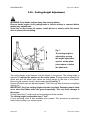
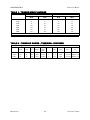
1
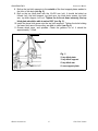
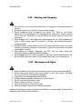
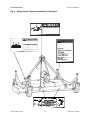
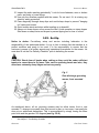
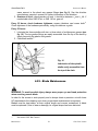
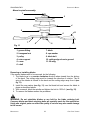
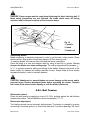
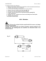
OPERATOR’S MANUAL Operator's Manual Finishing Mower 48”, 60” & 72” FM48 FM60 FM72 Cub Cadet Yanmar LLC. P.O. Box 368023 Cleveland, OH 44136 PRINTED IN U.S.A. Version 2.0 Code No.:769-03315 Take note! This safety alert symbol found throughout this manual is used to call your attention to instructions involving your personal safety and the safety of others. Failure to follow these instructions can result in injury or death. This symbol means: ATTENTION! BECOME ALERT! YOUR SAFETY IS INVOLVED! Signal Words Note the use of the signal words DANGER, WARNING and CAUTION with the safety messages. The appropriate signal words for each has been selected using the following guidelines: DANGER: indicates an imminently hazardous situation that, if not avoided, will result in death or serious injury. WARNING: indicates a potentially hazardous situation that, if not avoided, could result in death or serious injury, and includes hazards that are exposed when guards are removed. It may also be used to alert against unsafe practices. CAUTION: indicates a potentially hazardous situation that, if not avoided, may result in minor or moderate injury. 1 - GENERAL INFORMATION 1.01 - General 1.02 - Model and Serial Number ID 1.03 - Assembly Instructions 2 - SAFETY PRECAUTIONS 2.01 - Preparation 2.02 - Starting and Stopping 2.03 - Messages and Signs 3 - OPERATION 3.01 - Operational Safety 3.02 - Set Up 3.03 - Cutting Height Adjustment 3.04 - Pre-Operational Check 3.05 - Attaching to the Tractor 3.06 - Start Up 3.07 - Working Speed 3.08 - Operating Techniques 3.09 - Uneven Terrain 3.10 - Removing Mower from the Tractor 4 - MAINTENANCE 4.01 - Maintenance Safety 4.02 - Service 4.03 - Blade Maintenance 4.04 - Belt Tension 4.05 - Belt Replacement 4.06 - Driveline 4.07 - Transport 5 - REPAIR PROCEDURES 5.01 - Gearbox 5.02 - Blade Spindle 5.03 - Suggested Spare Parts 5.04 - Storage 6 - TROUBLESHOOTING 7 - PRE-DELIVERY CHECKLIST 8 - PARTS MANUAL INDEX 3 4 4 4 5 7 7 8 8 10 10 12 13 13 14 15 16 16 18 18 19 19 20 21 23 24 25 26 29 29 29 29 30 31 32 33 CUB CADET YANMAR FM48/FM60/FM72 OPERATOR’S MANUAL 1 - GENERAL INFORMATION Thank you and congratulations for having chosen our implement. Your new grooming mower is a technologically advanced machine constructed of high quality sturdy components that will fulfill your working expectations. Read this manual carefully. It will instruct you on how to operate and service your mower safely and correctly. Failure to do so could result in personal injury and/or in equipment damage. 1.01 - General CAUTION: All hardware is metric. Only metric tools should be used. Other tools that do not fit properly can slip and cause injury. CAUTION: Right hand and left hand sides of the implement are determined by facing in the direction the implement will travel when going forward (see fig. 4). 1.02 - Model and Serial Number ID Attached to the frame is an ID plate showing the model and the serial number. Record your implement model and serial number in the space provided below. Your dealer needs this information to give you prompt, efficient service when you order parts. Model #: Serial #: GENERAL INFORMATION 4 CUB CADET YANMAR FM48/FM60/FM72 OPERATOR’S MANUAL Warranty does not cover the following: 1. Cleaning, transporting, mailing and service call charges. 2. Normal wear items such as belts, blades, bearings, drivelines, shear pins, slip clutches, etc. 3. Depreciation or damage caused by normal wear, accidents, improper maintenance, improper protection or improper use. 4. The use of non original spare parts and accessories. Your Authorized Company Dealer has genuine parts in stock. Only these approved replacement parts should be used. This limited warranty covers defective material and workmanship. The cost of normal maintenance or repairs for accidents or improper use and related labor will be borne by the owner. 1.03 - Assembly Instructions 4 5 1 2 3 6 7 8 Fig. 2 1. inner spacer 2. top hitch plate 3. top hitch support 4. bolt 5. top hitch arm 6. lower hitch arm 7. front support plate 8. front roller 1. Unbolt the wheel arms and discard the mounting bracket. 2. Separate the wheel arms and remove the hardware bag secured between them. 3. Important: Remove the belt shields to inspect around the belt area and under the gearbox central plate to be sure the area is clear of packing material such as blocks of wood, paper, etc. 4. Bolt the wheel arm assemblies to the mower deck with the flat washer and lock nuts. There is no difference between left/right or front/rear. Be sure both assemblies are securely mounted. 5. Assemble each wheel to the yokes with one 14x140 mm. bolt and one inner bushing. Tighten down snugly. The wheel should turn freely but have no side to side movement. 6. Replace the belt shields. 7. Bolt up the top hitch arms to the inside of the rear support plates on the rear of the mower (see fig. 3). GENERAL INFORMATION 5 CUB CADET YANMAR FM48/FM60/FM72 OPERATOR’S MANUAL 8. Bolt up the top hitch supports to the outside of the front support plates welded to the front of the deck (see fig. 2). 9. Bolt up the top hitch plate with the 16x150 mm. bolt. It should be bolted as follows: bolt, top hitch support, top hitch arm, top hitch plate, spacer, top hitch arm, top hitch support, lock nut. Tighten the lock nut down securely, the top hitch plate should be able to swivel 360° (see fig. 2). 10. Install the lower hitch arms onto the top hitch supports. Tighten the bolts holding the lower hitch arms. Be sure they are able to swivel (see fig. 2). 11. Grease wheel arms, and spindles. Check the gearbox for oil. It should be approximately 1/2 filled. 2 3 5 Fig. 3 2. top hitch plate 3. top hitch support 5. top hitch arm 9. rear support plate 9 GENERAL INFORMATION 6 CUB CADET YANMAR FM48/FM60/FM72 OPERATOR’S MANUAL 2 - SAFETY PRECAUTIONS Safety is the primary concern in the design and manufacture of our products. Unfortunately our efforts to provide safe equipment can be wiped out by a single careless act of an operator. In addition to the design and configuration of equipment, hazard control and accident prevention are dependent upon the awareness, concern, prudence and proper training of personnel involved in the operation, transport, maintenance and storage of equipment. It is the operator's responsibility to read and understand all safety and operating instructions in the manual and to follow these. Allow only properly trained personnel to operate the mower. Working with unfamiliar equipment can lead to careless injuries. Read this manual, and the manual for your tractor, before assembly or operating, to acquaint yourself with the machines. It is the mower owner's responsibility, if this machine is used by any person other than yourself, is loaned or rented, to make certain that the operator, prior to operating, reads and understands the operator's manuals and is instructed in safe and proper use. 2.01 - Preparation 1. Before operating equipment read and understand the operator's manual and the safety signs (see fig. 4). 2. Thoroughly inspect the implement before initial operation to assure that all packaging materials, i.e., wires, bands, and tape have been removed. 3. Personal protection equipment including hard hat, safety glasses, safety shoes, and gloves are recommended during assembly, installation, operation, adjustment, maintaining and/or repairing the implement. 4. Operate the mower only with a tractor equipped with an approved Roll-Over-Protective-System (ROPS). Always wear your seat belt. Serious injury or even death could result from falling off the tractor. 5. Clear area to be cut of stones, branches or other debris that might be thrown, causing injury or damage. 6. Operate only in daylight or good artificial light. 7. Ensure mower is properly mounted, adjusted and in good operating condition. 8. Ensure that all safety shielding and safety signs are properly installed and in good condition. SAFETY PRECAUTIONS 7 CUB CADET YANMAR FM48/FM60/FM72 OPERATOR’S MANUAL 2.02 - Starting and Stopping 1. Be sure that no one is near the machine prior to engaging or while the machine is working. 2. Be sure the tractor is in "Neutral" before starting engine. 3. Mower operating power is supplied from tractor PTO. Refer to your tractor manual for PTO engagement and disengagement instructions. Always operate PTO at 540 rpm. Know how to stop the tractor and mower quickly in case of an emergency. 4. When engaging PTO, the engine rpm should always be low. Once engaged and ready to start cutting, raise PTO speed to 540 rpm and maintain throughout cutting operation. 5. Check the tractor master shield over the PTO stub shaft. Make sure it is in good condition and fastened securely to the tractor. Purchase a new shield if old shield is damaged or missing. 6. After striking an obstacle, disengage the PTO, shut the tractor down and thoroughly inspect for damage before restarting. 7. Never engage the PTO until the mower is in the down position and resting on the ground. Never raise the mower until all blades have come to a complete stop. 2.03 - Messages and Signs 1. Read and adhere to all safety and operating decals on this machine (see fig. 4). 2. Before dismounting tractor: allow moving parts to stop, stop engine, set brake and remove the key of unattended equipment. 3. Keep away from rotating blades and driveline. 4. Keep guards and shields in place and in good condition. 5. Do not mow with bystanders in area. 6. Allow no riders on tractor or mower. 7. Allow moving parts to stop before repair. 8. Securely support mower before working underneath. Additional warning and operating decals are available at no extra charge. Please specify model and serial number when ordering. SAFETY PRECAUTIONS 8 CUB CADET YANMAR FM48/FM60/FM72 OPERATOR’S MANUAL Fig. 4 - Safety Decals; Replace immediately if damaged. SAFETY PRECAUTIONS 9 CUB CADET YANMAR FM48/FM60/FM72 OPERATOR’S MANUAL 3 - OPERATION You have purchased a three spindle mower designed especially for the mowing of grassy areas where a highly professional cut is required without wasting time. This mower is perfect for the maintenance of parks, private lawns, industrial parks, airports, hospital grounds, schools, highways, golf courses, sport complexes, etc. The grooming mower, for tractors up to 30 HP, come in working widths of 4’, 5' and 6'. The mower can be either tractor front or rear mounted and is available in rear discharge. On your mower, the tractor PTO transmits its power through a driveline to a speed multiplier gearbox. A pulley is attached to the pinion gear shaft of the gearbox which, via high resistance belts, transmits power to pulleys coupled to the three individual spindle shafts. Blades are secured to these shafts which turn at a high blade tip speed to cut the grass. Our grooming mower comes equipped with 4 swivel wheels. Aside from regulating the cutting height, the wheels are set in such a way as to allow the mower to follow the contour of the terrain and give a precise level cut even in undulating conditions. 3.01 - Operational Safety CAUTION: Our mowers are designed considering safety as the most important aspect and are the safest available in today's market. Unfortunately, human carelessness can override the safety features built into our machines. Injury prevention and work safety, aside from the features on our mowers, is very much due to the responsible use of the equipment. It must always be operated prudently following with great care, the safety instructions laid out in this manual. 1. The use of this equipment is subject to certain hazards which cannot be prevented by mechanical means or product design. All operators of this equipment must read and understand this entire manual, paying particular attention to safety and operating instructions, prior to using. 2. Do not operate the tractor and mower when you are tired, sick or when using medication. 3. Keep all helpers and bystanders at least several feet from a rotary mower. Only properly trained people should operate this machine. 4. The majority of accidents involve entanglements on the driveline, injury of bystanders by objects thrown by the rotating blades, and operators being knocked off the tractor by low hanging limbs and then being run over by the mower. Accidents are most likely to occur with machines that are loaned or OPERATION 10 CUB CADET YANMAR FM48/FM60/FM72 OPERATOR’S MANUAL rented to someone who has not read the operator's manual and is not familiar with a rotary mower. 5. Always stop the tractor, set brake, shut off the tractor engine, remove the ignition key, lower implement to the ground and allow mower blades to come to a complete stop before dismounting tractor. Never leave equipment unattended with the tractor running. 6. Never place hands or feet under mower with tractor engine running or before you are sure all motion has stopped. Stay clear of all moving parts. 7. Do not allow riders on the mower or tractor at any time. There is no safe place for riders. 8. Do not operate unless all personnel, livestock and pets are several feet away to prevent injury by thrown objects. 9. Before backing up, disengage the mower and look behind carefully. 10. Install and secure all guards and shields before starting or operating. 11. Keep hands, feet, hair and clothing away from moving parts. 12. This rotary mower is designed for use only on tractors with 540 rpm power take off. 13. Never operate tractor and mower under trees with low hanging limbs. Operators can be knocked off the tractor and then run over by the rotating blades. 14. The rotating parts of this machine have been designed and tested for rugged use. However, they could fail upon impact with heavy, solid objects such as steel guard rails and concrete abutments. Such impact could cause the broken objects to be thrown outward at very high velocities. To reduce the possibility of property damage, serious injury, or even death, never allow the cutting blades to contact such obstacles. 15. Frequently check mower blades. They should be sharp, free of nicks and cracks and securely fastened. 16. Stop mower immediately upon striking an obstruction. Turn engine off, remove key, inspect and repair any damage before resuming operation. 17. Stay alert for holes, rocks and roots in the terrain and other hidden hazards. Keep away from drop-offs. 18. Use extreme care and maintain minimum ground speed when transporting on hillside, over rough ground and when operating close to ditches or fences. Be careful when turning sharp corners. 19. Reduce speed on slopes and sharp turns to minimize tipping or loss of control. Be careful when changing directions on slopes. Do not start or stop suddenly on slopes. Avoid operation on steep slopes. 20. When using a unit, a minimum 20% of tractor and equipment weight must be on tractor front wheels. Without this weight, tractor could tip over, causing personal injury or death. The weight may be attained with a front end loader, front wheel weights, ballast in tires or front tractor weights. When attaining a minimum 20% of tractor and equipment weight on the front wheels, you must not exceed the ROPS weight certification. Weigh the tractor and equipment. Do not guess or estimate! OPERATION 11 CUB CADET YANMAR FM48/FM60/FM72 OPERATOR’S MANUAL 21. Inspect the entire machine periodically1. Look for loose fasteners, worn or broken parts, and leaky or loose fittings. 22. Use only the driveline supplied with the mower. Do not use it if it is missing any shield or safety protection. 23. Pass diagonally through sharp dips and avoid sharp drops to prevent "hanging up" tractor and mower. 24. Avoid sudden starts and stops while traveling up or downhill. 25. Always cut down slopes; never across the face. Avoid operation on steep slopes. Slow down on sharp turns and slopes to prevent tipping and or loss of control. 3.02 - Set Up Notice to dealer: Pre-delivery setup and service including lubrication is the responsibility of the authorized dealer. It is up to him to assure that the machine is in perfect condition and ready to be used. It is his responsibility to ensure that the customer is aware of all safety aspects and operational procedures for the mower. He must also fill out the Pre-Delivery Checklist2 prior to delivering the mower. CAUTION: Stand clear of bands when cutting as they could be under sufficient tension to cause them to fly loose. Take care in removing bands and wire, they often have extremely sharp edges and cut very easily. Fig. 5 Rear discharge grooming mower, front mounted. As mentioned above, all our grooming mowers may be either tractor front or rear mounted. To change our mowers from front mount to rear, or vice versa, it can easily be done at our authorized dealerships. This is accomplished by simply turning the three point hitch and the gearbox 180 degrees (see fig. 5 & 6). 1 2 See chapter 4 - Maintenance. See chapter 7 - Pre-Delivery Checklist. OPERATION 12 CUB CADET YANMAR FM48/FM60/FM72 OPERATOR’S MANUAL 3.03 - Cutting Height Adjustment WARNING: Keep hands and feet away from moving blades. Be sure tractor engine is off, parking brake is locked, and key is removed before making any adjustments. Never rely on the tractor lift system. Install blocks or stands under the mower deck to prevent it from falling. Fig. 7 The cutting height is adjusted by moving the height adjustment spacers on the wheel yokes above or below the wheel arm. The cutting height is the distance from the blades to the ground. The cutting height is adjusted by moving the spacers on the wheel yokes. Placing spacers between the wheel arm and the wheel yoke raises the cutting height by the size of the spacer. Removing the spacers, lowers it by the same height (see fig. 7). Be sure all wheel arms are adjusted equally. This is the only way to ensure a completely uniform cut. IMPORTANT: Very low cutting heights should be avoided. Damaging shock loads occur when the blades strike the ground repeatedly. This can cause damage to the mower. Cutting lower than 2" under most circumstances should be avoided. The cutting height is adjustable from 1" to 4". A front anti-scalp roller is also available upon request. This accessory is particularly helpful when cutting over uneven terrain. OPERATION 13 CUB CADET YANMAR FM48/FM60/FM72 OPERATOR’S MANUAL 3.04 - Pre-Operational Check Check each of the following, carefully, prior to engaging the equipment: 1. The spindle bearings have been greased. 2. The belts for proper tension. 3. The oil in the gearbox. 4. The driveline cross & bearings have been greased. 5. No wrappings or foreign objects are around the blades, belts or driveline. 6. The blades are properly installed and the blade bolts properly torqued3. 7. All hardware is tight. 8. The tractor, to ensure correct direction of PTO and rpm speed. 9. All safety shields and guards are in place and tightly attached. 10. No people or animals are in the work area. 11. When working, make sure the tractor hitch is in the "float" position, in order to allow the mower to follow the contour of the ground. DANGER: Stay clear of rotating driveline. Entanglement in rotating driveline can cause serious injury. Disengage PTO, engage parking brake or place transmission in "Park", shut off the tractor and remove the key before working around hitch, attaching or detaching driveline, making adjustments, servicing or cleaning the machine. 3.05 - Attaching to the Tractor Only use this model implement with tractors in the correct power range4. Never use this mower with tractors over 30 HP. CAUTION: Check the tractor PTO rpm to ensure it is set at 540 and turns clockwise. CAUTION: Always ensure that the tractor tire pressure is correct according to the tractor operator's manual. DANGER: Failure to ensure a secure coupling of the implement to the tractor can cause injury and damage to the implement or tractor. 3 4 See table 1, page 28. See table 2, page 28. OPERATION 14 CUB CADET YANMAR FM48/FM60/FM72 OPERATOR’S MANUAL To attach the mower to the tractor do the following: 1. Back the tractor up to the mower in order to slip the tractor hitch arms over the hitch pins welded to the mower hitch arms. Turn off the tractor engine. Secure them in place with the lynch pins. 2. Adjust the tractor sway blocks or chains to remove all side movement. 3. Attach the top link. Adjust tractor top link to allow the mower to follow the ground contour and yet remain as level as possible when raised to transport position. 4. Install the shielded driveline to the tractor by first lining up the splines and depressing the snap pin. Push the yoke onto the PTO shaft as far as it will go. Release the pin and pull back slowly until the pin clicks in place. Repeat this operation on the implement end. 5. Attach the driveline chains to the tractor and to the mower to keep the driveline protection from turning. The chains should not be too tight. 3.06 - Startup DANGER: The mower must always be lowered to the ground before starting tractor engine or engaging PTO lever. Lower mower to the ground with the tractor rock shaft control lever. With the engine idling, slowly engage the PTO drive. Move the throttle lever until the PTO speed indicated on the mower is obtained. The mower is set for a PTO speed of 540 rpm. Shift the transmission to a slow speed gear and start forward, increase the ground speed by shifting upward until the desired speed is obtained. Do not mow in reverse unless absolutely necessary and only after careful observation of the area behind the mower. CAUTION: Do not operate this mower at a PTO speed or direction of rotation other than that shown on the mower. Serious damage can occur to the machine and/or the operator. Before starting to mow, never forget that the operator is responsible for the following: 1. Safe and correct driving of the tractor and mower. 2. To learn precise safe operating procedures for both the tractor and the mower. 3. To ensure all maintenance and lubrication has been performed on the mower. 4. To have read and understood all safety aspects for the mower in the operator's manual. 5. To have read and understood all safety decals on the mower. 6. Checking the condition of the blades. Worn or damaged blades should be changed before starting5. 5 See section 4.03 - Blade Maintenance. OPERATION 15 CUB CADET YANMAR FM48/FM60/FM72 OPERATOR’S MANUAL 7. Checking to ensure that the cutting edge is the leading edge of the blade6. 8. Checking that there is no wire, weed, grass or other material wrapped around blades. 9. Checking to see if front weights need to be added to the tractor in order to maintain balance. 10. Checking the tractor tires for the proper pressure in accordance with the tractor operator's manual. 11. Checking the side discharge chute (on side discharge mowers only) to ensure that it is properly in place. Checking that the PTO shield, belt shields and all other shielding are on the machine and securely in place. 12. Making sure the proper attire is worn. Avoiding loose fitting clothing which can become entangled. Wearing sturdy, tough-soled work shoes and protective equipment for eyes, hands, ears and head. Never operate tractor or implements in bare feet, sandals or sneakers. 13. Checking area for stones, branches and other debris that might be thrown. 14. Ensuring proper lighting is available, sunlight or good artificial lighting. 3.07 - Working Speed The mowing speed depends on ground conditions, tractor HP, mowing height, and grass thickness. Only a test run will enable you to gauge the optimal working speed for your conditions. Under most conditions a 3 to 8 mph ground speed is best. As a rule of thumb, and if the conditions permit, grass dispersion is increased by higher ground speeds. In order to obtain the best cut possible, always keep the tractor rpm up to the speed indicated on the mower. When increasing or decreasing mowing ground speed, always use gear selection, not engine speed. This will maintain the constant maximum blade speed necessary for a clean cut. 3.08 - Operating Techniques All of the following factors are important in selecting the proper forward speed: 1. Height of grass. 2. Type of grass. 3. Density of grass. 4. Type of terrain. 5. Grass condition, wet or dry. This mower has been designed to cut grass with heights from 4" to 8". It is recommended to avoid cutting grass taller than 10". For the best results, try cutting the grass at least once per week during growing season. Tall, dense grass should be cut at low speed, while thin medium grass can be cut at a faster ground speed. For cleaner cuts and efficient mowing, the blades must be kept sharp7. 6 7 See section 4.03 - Blade Maintenance. See Sharpening Blades in section 4.03 - Blade Maintenance. OPERATION 16 CUB CADET YANMAR FM48/FM60/FM72 OPERATOR’S MANUAL Always operate PTO at 540 rpm. This is necessary to maintain proper blade speed and obtain a clean cut. Under certain conditions, tractor tires may roll some grass down and prevent it from being cut at the same height as the surrounding area. If this occurs reduce the tractor ground speed but maintain a 540 rpm engine speed. The lower ground speed will permit the grass to at least partially rebound. Under some conditions grass will not rebound enough to be cut even, resulting in an uneven appearance. In general, lower cutting height gives a more even cut with less tendency to leave tire tracks. If cut is still not satisfactory, cut the area twice. Mow extremely tall grass twice. On the first pass use a high cutting height. On the second pass position the mower at the desired height and when practical, mow at a right angle in travel to the first pass. Plan your pattern to travel straight forward whenever possible. It is better to cut grass more often, than too short. Short grass deteriorates rapidly in hot weather and invites weed growth during growing season. If at any time the mower should jam resulting in belt slippage of 2 or more seconds, raise the mower and continue for 2-3 minutes. This will allow the pulleys to cool and prolong belt life. DANGER: The mower blades can throw objects hundreds of feet which could result in personal or property damage. Pick up all rocks and other debris before mowing. Enter new areas carefully. Cut grass higher at first, allowing mower to clear hidden objects. CAUTION: For emergency reasons learn how to stop the tractor and mower quickly. On the grooming mowers always disengage the PTO, lock parking brake, stop engine and allow the mower blades to come to a complete stop before dismounting the tractor. OPERATION 17 CUB CADET YANMAR FM48/FM60/FM72 OPERATOR’S MANUAL 3.09 - Uneven Terrain DANGER: Be careful of rollover when operating tractor and mower over uneven ground. In extremely uneven terrain rear wheel weights, front tractor weights, and/or tire ballast should be used to improve stability. When mowing over uneven terrain, observe the type of terrain and develop a safe mowing pattern. Whenever traction or stability is doubtful, first test drive over the terrain with the PTO disengaged. Operate the mower up and down steep slopes, not across slopes, to prevent the tractor from tipping. Avoid sudden stops and starts, and slow down before changing directions on a slope. Pass diagonally through sharp dips and avoid sharp drops to prevent hanging up the tractor and mower. Slow down on sharp turns and slopes to prevent tipping or loss of control. Avoid tipping the mower while cutting. Watch for holes, roots or other hidden objects. Do not cut near the edge of a gully, ditch or stream bank. 3.10 - Removing Mower from the Tractor CAUTION: Disengage tractor PTO. Set parking brake. Stop engine and remove key from ignition. Disconnect mower driveline from tractor PTO shaft. Collapse driveline and store in appropriate place. Disconnect three point linkage and carefully drive tractor away from mower. OPERATION 18 CUB CADET YANMAR FM48/FM60/FM72 OPERATOR’S MANUAL 4 - MAINTENANCE DANGER: Stop engine, lock parking brake and remove key before performing any service or maintenance. Never rely on the tractor lift system. Install blocks or stands under the mower deck to prevent it from falling. Always use personal protection devices, such as glasses or gloves when performing maintenance. Keep fingers out of slots to prevent injury. 4.01 - Maintenance Safety 1. Good maintenance is your responsibility. 2. Keep service area clean and dry. Be sure electrical outlets and tools are properly grounded. Use adequate light for the job at hand. 3. Make sure there is plenty of ventilation. Never operate the engine of the towing vehicle in a closed building. The exhaust fumes may cause asphyxiation. 4. Make no repair or adjustments with the tractor engine running. Before working on the machine, disengage the PTO, shut off the engine, set the brakes, and remove the ignition key. 5. Be certain all moving parts on attachment have come to a complete stop before attempting to perform maintenance. 6. Never work under equipment unless it is blocked securely. 7. Always use personal protection devices such as eye, hand and hearing protectors, when performing any service or maintenance. 8. Frequently check mower blades. They should be sharp, free of nicks and cracks and securely fastened. 9. Periodically tighten all bolts, nuts and screws and check that all cotter pins are properly installed to ensure unit is in a safe condition. 10. When completing a maintenance or service function, make sure all safety shields and devices are installed before placing unit in service. 11. Do not attempt to mount a tire unless you have the proper equipment and experience to do the job. 12. Inflating or servicing tires can be dangerous. Whenever possible, trained personnel should be called to service and/or mount tires. 13. After servicing, be sure all tools, parts and service equipment are removed. MAINTENANCE 19 CUB CADET YANMAR FM48/FM60/FM72 OPERATOR’S MANUAL 14. Never replace hex bolts with less than grade five bolts unless otherwise specified, i.e., shear bolts8. 15. Where replacement parts are necessary for periodic maintenance and servicing, genuine replacement parts must be used to restore your equipment to original specifications. The company will not claim responsibility for use of unapproved parts and/or accessories and other damages as a result of their use. 16. Unauthorized modifications to the machine may impair the function and/or safety of the machine and reduce its life. If equipment has been altered in any way from original design, the manufacturer does not accept any liability for injury or warranty. 4.02 - Service The accompanying illustrations show lubrication points. The chart gives the frequency of lubrication in hours, based on normal operating conditions. Severe or unusual conditions may require more frequent lubrication. Use a good quality SAE multipurpose type grease for all locations shown. Be sure to clean fittings thoroughly before using grease gun. Use 90 wt. gear oil in gearbox. Hourly: 1. Check the condition of mower blades for nicks or dull edges. Sharpen if necessary. 2. Replace bent or damaged blades9. 3. Also check blades for damage after hitting an obstruction. 4. Clean foreign material from mower deck and belt area. Fig. 9 Lubrication of wheel yokes. Every 8 hours: 1. Lubricate the driveline and the wheel yokes: apply two or three shots of grease to the driveline cross and bearings and the telescoping shafts; apply the 8 9 Refer to table 1 - Torque Specifications, for head identification marking. See section 4.03 - Blade Maintenance. MAINTENANCE 20 CUB CADET YANMAR FM48/FM60/FM72 OPERATOR’S MANUAL same amount to the wheel arm grease fittings (see fig. 9). See the driveline manufacturer operator's manual for further information on the driveline. 2. Gearbox oil level: check gearbox oil level, it should be between 1/2 and 2/3 full. If needed add either SAE 90 wt. or SAE 140 wt. gear oil. Every 25 hours: check hardware tightness; mower vibrations can loosen bolts10. Check tightness of the hardware periodically, using this table as a guide. Every 50 hours: 1. Lubricate the three spindles with two or three shots of multipurpose grease (see fig. 10). The top grease fittings are easily accessible from the top of the deck by simply removing the plastic dust guards. 2. Check belt tension11. Fig. 10 Lubrication of the spindle shafts easily accessible from the top of the deck. 4.03 - Blade Maintenance WARNING: To avoid possible injury always wear proper eye and hand protection when servicing mower blade. In order for the mower to work properly and to always obtain a precision cut with lower HP requirements thus keeping cost down, proper blade maintenance is important. Blades must be kept sharp, at their original length and corners maintained. A blade must be replaced if, due to wear or damage, its original shape has been distorted. 10 11 See table 1, page 28. See section 4.04 - Belt Tension. MAINTENANCE 21 CUB CADET YANMAR FM48/FM60/FM72 OPERATOR’S MANUAL Mower's spindle assembly. 1 2 3 4 5 6 7 8 9 Fig. 11 11 10 Ground 7. blade 8. cup washer 9. blade bolt 10. cutting edge close to ground 11. lift wing 1. grease fitting 2. hexagonal nut 3. pulley 4. rotor support 5. cover 6. shaft Removing or installing blades If the mower blades need to be removed, do the following: 1. The blade turns in a counter clockwise direction when viewed from the bottom of the deck. The cutting edge must be towards the direction of rotation. The lift wing of the blades is closest to the deck and the cutting edge away from it (see fig. 11). 2. Install the cup washer (see fig. 11) over the blade bolt and secure the blade in place as described above. 3. With a wrench, block the spindle and tighten the bolt to 103 lb.ft. (see fig. 12). 4. To remove the blades reverse the procedure. WARNING: Do not substitute blades or any bolt for the blade retaining bolt. Company blades and blade retaining bolts are specially made for this application. Using non original parts can effect the quality of cut and may also cause damage to the mower. MAINTENANCE 22 CUB CADET YANMAR FM48/FM60/FM72 OPERATOR’S MANUAL DANGER: Proper torque must be used when tightening the blade retaining bolt. If these safety precautions are not followed, the blade could come off during operation and be thrown hundreds of feet from the mower. 1 2 Fig. 12 1. spindle 2. blade 3. blade bolt 3 Sharpening Blades Blade sharpening is extremely important in order to get the best cutting results. Sharp blades permit a high quality cut and also reduces HP thus lowering cost. To sharpen blades, first remove them following the above instructions. Place the blade in a vise and sharpen them by using a hand file or grinder. Do not sharpen the blades to a sharp cutting edge. The cutting edge should be between 1/64" to 1/32" to prevent excessive pitting and dulling of the blades. Sharpen both ends of the blade equally for balance and always maintain corners. Always keep all three blades sharpened equally in order to maintain balance. CAUTION: Unbalanced or warped blades can cause damage to the mower and/or personal injury. Replace damaged blades before operating the mower. Sharpen both ends of the mower blades equally or until the blade is balanced. 4.04 - Belt Tension Belt tension control Check the belt tension by applying a force of 12-15 lb. pushing against the belt halfway between the pulleys. The belt deflection should be between 5/16"-3/8". Belt tension adjustment The finishing mower has an automatic belt tensioner. The tension is created by a spring connecting a tensioner pulley to a fixed hitch plate with 3 positions (see fig. 13). Upon MAINTENANCE 23 CUB CADET YANMAR FM48/FM60/FM72 OPERATOR’S MANUAL delivery, the spring is located in the first position. When the belt stretches after use, adjust the tension by relocating the spring in the other two holes. If the belt has stretched to the point that the belt is not tight enough even in the last hole it is necessary to replace the belt. 1 2 3 Fig. 13 1. tensioner 2. belt 3. pulley 4. spring 5. hitch plate 5 4 4.05 - Belt Replacement If the belt has been stretched or damaged to the point where the proper tension can not be obtained it must be changed. 7 3 5 MAINTENANCE 6 2 5 3 4 1 24 Fig. 14 1. drive pulley 2. central pulley 3. side pulley 4. belt 5. belt tensioner 6. hitch plate 7. spring CUB CADET YANMAR FM48/FM60/FM72 OPERATOR’S MANUAL To replace the belt do the following: 1. Remove belt shields. Clean foreign material from the mower deck and belt area. 2. Release spring tensioner to loosen belt. 3. Loosen rear nuts holding central plate (do not remove them). 4. Remove front nuts holding central plate (see fig. 13). 5. Lift the front of the central plate and remove old belt. 6. Replace new belt starting from the right spindle pulley (see fig. 14). 7. Lower central plate. 8. Replace front nuts. Tighten front and rear nuts holding down central plate. 9. Replace spring tensioner. 10. Reinstall the belt shields. 4.06 - Driveline DANGER: Only use the original driveline supplied with this mower, and always with the safety shielding. Carefully read and file away the driveline operator's manual supplied by the manufacturer. The following does not substitute the information found in the driveline manual. Fig. 15 min. 6" MAX. min. 2" MIN. MAINTENANCE 25 CUB CADET YANMAR FM48/FM60/FM72 OPERATOR’S MANUAL In the collapsed position the driveline should be approximately 2" from bottoming out to prevent possible damage to the tractor or implement. When the PTO is in the maximum extended position, the ideal minimum overlap of the two halves should be approximately 6" (see fig. 15). If determined that the driveline is too long. Follow these procedures to adjust the length: 1. Separate the two driveline halves. Connect one half to the tractor PTO and the other half to the mower. 2. Raise and lower the mower with the 3 point hitch to find the position where the driveline is shortest. Hold the half shafts side by side and mark the desired length on the outer female tube guard leaving a 11/2" gap between the end of the guard tube and bell guard. 3. Cut off both guard tubes the same amount as marked in step 2. 4. Shorten both drive tubes the same amount as guard tubes. 5. De-burr and clean filings from drive tubes and apply grease to outside of inner telescoping tube. Reassemble the driveline halves and connect to tractor and mower. Raise and lower mower again to be sure driveline does not bottom out in its shortest position and has a minimum overlap of 6" in the longest position. CAUTION: Always work with the driveline as straight as possible. This will prolong its life and that of its components. It is advised not to work at an angle greater than 15 degrees. 4.07 - Transport Before raising the mower for transport, the tractor top link must be adjusted so when lifted, the rear of the machine is higher than the front (the mower's nose is tilted downward). To do this, shorten the tractor top link until the top hitch plate is locked forward and no longer able to pivot. This will keep the mower locked in position and minimize the shaking and bouncing during transport which can damage the hitch or frame. When raising the mower be sure the PTO driveline does not hit either the mower or the tractor. During transport the mower should not be lifted over 14"-16" from the ground. CAUTION: Make sure PTO is disengaged and blades have stopped turning before raising mower to full transport position. Do not tow tractor and mower behind other vehicles. Use a properly equipped trailer with heavy tie-downs for towing operations. MAINTENANCE 26 CUB CADET YANMAR FM48/FM60/FM72 OPERATOR’S MANUAL Before transporting: 1. Disengage PTO. 2. Shorten tractor top link until top hitch plate is locked. 3. Raise machine and lock rock shaft control lever. 4. Always select a safe ground speed that is appropriate for the terrain. 5. Beware of traffic on public roads. Install a SMV (Slow Moving Vehicle) sign when traveling on roads or streets. 6. Reduce ground speed when turning and take care that the mower does not strike obstacles such as trees, fences or buildings. MAINTENANCE 27 CUB CADET YANMAR FM48/FM60/FM72 OPERATOR’S MANUAL TABLE 1 - TORQUE SPECIFICATIONS Diameter Class 8.8 Class 10.9 N.m lb.ft N.m lb.ft M8 25 18 35 26 M 10 50 37 70 52 M 12 90 66 125 92 M 14 140 103 200 148 M 16 215 155 305 225 M 18 295 217 420 309 M 20 420 302 590 438 When using locks, nuts, increasing torque values by 5%. TABLE 2 - FINISHING MOWER - TECHNICAL FEATURES Rear Discharge, for tractors up to 30 HP, PTO 540 rpm, 3 point hitch cat. 1 Model Working width Overall width FM48 48” 51” 340 3037 13,188 FM60 60" 62” 375 2803 FM72 72" 74” 440 2278 MAINTENANCE Weight Rotor Blades tip # Blades lb. rpm/min speed ft/min # Belts & type 3 1” - 4" 1 BX 4 - 8.4"x3.2" ASAE 2nd. cat 14,763 3 1” - 4" 1 BX 4 - 8.4"x3.2" ASAE 2nd. cat 14,566 3 1” - 4" 1 BX 4 - 8.4"x3.2" ASAE 2nd. cat 28 # Wheels & size Driveline 1 3/8" Cutting height CUB CADET YANMAR FM48/FM60/FM72 OPERATOR’S MANUAL 5 - REPAIR PROCEDURES CAUTION: All repair procedures must be done by authorized dealerships. It is not recommended that untrained individuals perform any repair work. The following operations are detailed for qualified personnel only. 5.01 - Gearbox To remove the gearbox do the following: 1. Remove the belt12 (see fig. 13). 2. Remove the nut holding the pulley to the gearbox pinion shaft. 3. Remove the pulley. 4. Remove the nuts holding the gearbox to the central plate. 5. Remove the gearbox. If it is necessary to replace any part on the inside of the gearbox, it is important to replace oil seals or gaskets to ensure a tight fit when reassembling. To replace the gearbox, follow the above instructions in reverse order. 5.02 - Blade Spindle To remove a blade spindle do the following: 1. Remove the belt13. 2. Remove the nut holding the pulley to the spindle shaft (see fig. 11). 3. Remove the blades14. 4. Unbolt the bolts holding the rotor support to the mower deck. 5. If necessary remove and replace the bearings from the rotor using presses or extractors. 6. Reassemble in reverse order ensuring that the nut securing the top pulley (see fig. 11) is tightened to 108 lb.ft. 5.03 - Suggested Spare Parts It is suggested that the following spare parts be kept on hand for the finishing mower at all times to prevent a minor problem from delaying work. 12 13 14 See section 4.05 - Belt Replacement. See section 4.05 - Belt Replacement. See section 4.03 - Blade Maintenance. REPAIR PROCEDURES 29 CUB CADET YANMAR FM48/FM60/FM72 OPERATOR’S MANUAL Description Blades Blade bolts Washers Belts Quantity 3 3 3 1 5.04 - Storage After seasonal use it is important to perform the following for prolonged storage: 1. Wash the mower carefully. 2. Inspect the mower and replace worn or damaged parts. 3. Tighten all hardware. Grease all areas indicated under Maintenance15. 4. Loosen the belts if the mower is to be stored for an extended length of time. 5. Cover the mower from the elements in order to have it in perfect conditions for the start of the next season. 15 See chapter 4 - Maintenance. REPAIR PROCEDURES 30 CUB CADET YANMAR FM48/FM60/FM72 OPERATOR’S MANUAL 6 - TROUBLESHOOTING WARNING: Be sure tractor engine is off, parking brake is locked, and key is removed before making any adjustments. PROBLEM POSSIBLE CAUSE SOLUTION Uneven cutting. Cup washer not between blade and bolt. Ground speed too fast. Blades need sharpening. Caster wheels uneven Check washer location at all 3 spindles. Shift to lower gear. Sharpen blades. Adjust wheel position. Blades turning but not cutting. Direction of blades is wrong. Blade should turn counter clockwise rotation when you face deck bottom. See Installing Blade section. Belt slippage. Lack of tension. Object clogging mower. Debris in pulleys. Tighten belt. Remove object. Clean pulleys. Mower vibrates. Object wrapped around blade. Remove object. Belt damaged. Replace belt. Belt squeal. Belt slipping. Tighten belt. Grass build up at exit. Wet grass. Grass too high. Allow grass to dry. Raise mower, shift to lower gear, make two passes over grass. Mow grass high 1st pass, 2nd pass cut to desired height. Increase tractor rpm, check engine and PTO speeds. Tractor rpm too slow. Belts are tight when Wrong belt size. installing. Installed belts incorrectly. Check belt size. See Replacing Belts section. Streaking conditions Too wet to mow. in swath. Blades cannot cut grass pressed down by wheels. Dull blades. Allow grass to dry. Maintain engine speed and shift to lower gear. Sharpen blade. See Sharpening Blades section. Blades worn down, preventing Change blades. overlap. Cut grass windrows. Ground speed too low. Tractor rpm too slow. TROUBLESHOOTING 31 Increase ground speed. Increase tractor rpm, check engine and PTO speeds. CUB CADET YANMAR FM48/FM60/FM72 OPERATOR’S MANUAL 7 - PRE-DELIVERY CHECKLIST To the dealer: Inspect the machine thoroughly after assembly to assure it is functioning properly before delivering it to the customer. The following checklist is a reminder of points to cover. Check off each item as it is found satisfactory or after proper adjustment is made. Gearbox oil level. Guards and shield properly fastened. Lubrication of grease fittings. All hardware properly tightened. All decals properly located and readable (see fig. 4). Blades properly installed, blade bolts & nuts tightened. Overall condition (touch up scratches, clean and polish). Test run, check for excessive vibration or overheating of bearings. Operator's Manual. Review the operator's manual with the customer. Explain the following: Warranty. Safe operation and service. Correct machine installation and operation. Daily and periodic lubrication, maintenance and inspections. Troubleshooting. Operational procedures and storage. Parts and service. Give customer the operator's manual and encourage the customer to read the manual carefully. Model Number: __________ Serial Number: __________ Delivery Date: __________ Dealer's Signature: __________ PRE-DELIVERY CHECKLIST 32 CUB CADET YANMAR 9 - PARTS MANUAL Finishing Mower 48”, 60” & 72” FM48 FM60 FM72 FM48/FM60/FM72 PARTS MANUAL OPERATOR’S MANUAL 34 CUB CADET YANMAR FM48/FM60/FM72 FRAME Ref. Part # Part Description 1 015-1501P 025-1501P 035-1501P 010-8817 020-8817 030-8817 005-1581 005-1583 005-1585 000-6647 020-8425 005-1858 005-1859 005-1856 000-8818 001-4106 003-0157 003-3176 000-2034 003-0156 000-1280 000-1279 000-6349 001-5237 000-1077 000-3038 000-8663 005-1570 Frame 48” Rear Discharge (Version B) Frame 60” Rear Discharge (Version B) Frame 72” Rear Discharge (Version B) Belt Shield 48” (Version A) Belt Shield 60” (Version A) Belt Shield 72” (Version A) Central Plate 48” Central Plate 60” Central Plate 72” Cap Deflector 60” Side Rear Protection 60” Side Rear Protection 72” Central Rear Protection Bolt TE 10 x 110 Nut D. 10 Flat Waher D. 10 Bolt TE 10 x 110 Flat Washer D. 10 Nut D. 10 Spring Washer D. 10 Nut D. 10 Bolt TE 10 x 110 Nut D. 10 Spring Washer D. 12 Nut D. 12 Shaft Protection (EC Only) Cap 3 4 5 6 7 8 9 10 11 12 13 14 15 16 17 18 19 20 21 22 PARTS MANUAL 35 OPERATOR’S MANUAL Qty. 1 1 1 2 2 2 1 1 1 3 1 2 2 2 2 2 2 4 2 4 4 1 - CUB CADET YANMAR FM48/FM60/FM72 PARTS MANUAL OPERATOR’S MANUAL 36 CUB CADET YANMAR Ref. Part # Part Description 1 2 005-6511 015-6521 025-6521 035-6521 000-6829 000-6828 000-6891 000-5581 003-2687 000-6578 003-7349 003-0358 005-6525 001-8266 000-8785 000-6610 000-8528 000-6615 010-8761 020-8761 030-8761 000-1065 000-6586 000-6587 000-6589 0026185 003-0157 000-2034 000-1280 000-1279 000-1278 003-0156 005-6523 002-2433 002-2435 Top Hitch Support (Version A) Top Hitch Arm 48” (Version A) Top Hitch Arm 60” (Version A) Top Hitch Arm 72” (Version A) Spacer since 1/2007 Upper Plate Bolt TE 16 x 140 Nut D. 16 Bolt TE 16 x 40 Bolt TE 16 x 45 Bolt TE 14 x 45 Nut D. 14 Hitch Block since 1/3/2005 Lynch Pin Wheel Yoke Cotter Pin Spacer Bolt TE 14 x 140 Wheel Arm 48” Wheel Arm 60” Wheel Arm 72” Grease Fitting Spacer 1” Spacer 1/2” Spacer 1/4” Bolt TE 10 x 90 Flat Washer D. 10 Flat Washer D. 10 Spring Washer D. 10 Nut D. 10 Bolt TE 10 x 30 Nut D. 10 Linking Plate Driveline Hook (EC Only) Hook Support (EC Only) 3 4 5 6 7 8 9 10 11 12 13 14 15 16 17 18 19 20 21 22 23 24 25 26 27 28 29 30 31 PARTS MANUAL 37 Qty. 2 2 2 2 1 1 1 9 4 4 2 6 2 2 4 4 4 4 2 2 2 4 8 4 8 2 10 2 2 2 8 8 2 1 1 CUB CADET YANMAR FM48/FM60/FM72 PARTS MANUAL OPERATOR’S MANUAL 38 CUB CADET YANMAR FM48/FM60/FM72 Ref. 32 33 34 35 36 PARTS MANUAL Part # 005-4422 009-1446 000-3144 000-1806 000-8526 000-8797 OPERATOR’S MANUAL Part Description Cotter Pin D. 2 (EC Only) Bolt TE 8 x 25 Spring Washer D. 8 Nut D. 8 Hard Tire Air Tire 39 Qty. 1 1 1 1 4 4 CUB CADET YANMAR FM48/FM60/FM72 PARTS MANUAL OPERATOR’S MANUAL 40 CUB CADET YANMAR FM48/FM60/FM72 OPERATOR’S MANUAL Ref. Part # Part Description 1 000-8531 000-8666 000-8881 000-8561 000-8630 000-8670 000-8950 005-1740 000-8623 005-1741 005-1745 000-8571 005-1755 005-1757 009-1281 005-1751 005-1753 003-0156 009-1281 000-1279 000-8576 000-5508 004-6555 000-5507 000-6698 002-9036 000-1278 000-8559 000-8560 Pulley 120 x 1 48” Pulley 130 x 1 60” Pulley 160 x 1 72” Pulley Belt Tensioner Belt BX 98 48” Belt BX 112 60” Belt BX 140 72” Spring since 04/2007 Pulley 250 x 1 Belt Tensioner Support 48” since 04/2006 Belt Tensioner 60” & 72” since 04/2006 Hitch Plate 48” Hitch Plate 60” since 04/2006 Hitch Plate 72” since 04/2006 Bolt TE 10 x 35 Belt Tensioner Fixing Bolt since 04/2006 Flat Washer D. 16 since 04/2006 Nut D. 10 Bolt TE 10 x 35 Nut D. 10 Bolt TE 20 x 65 Nut D. 20 Flat Washer D. 20 Nut D. 20 Nut D. 25 Grease Fitting Bolt TE 10 x 30 Blade Bolt Disc Spring 2 3 4 5 6 7 8 9 10 11 12 13 14 15 16 17 18 19 20 21 PARTS MANUAL 41 Qty. 3 3 3 2 1 1 1 1 1 1 1 1 1 1 1 1 1 14 1 1 1 1 4 2 3 3 12 3 3 CUB CADET YANMAR FM48/FM60/FM72 PARTS MANUAL OPERATOR’S MANUAL 42 CUB CADET YANMAR FM48/FM60/FM72 Ref. 22 23 24 25 26 27 28 29 30 31 Part # 000-6795 000-6641 000-6845 000-6795M 000-6641M 000-6845M 000-6795B 000-6641B 000-6845B 000-6795F 000-6641F 000-6845F 000-8557 000-6639 000-6636 000-6606 000-6626 000-8538 000-8536 000-6634 000-8533 PARTS MANUAL OPERATOR’S MANUAL Part Description Standard Blade 48” Standard Blade 60” Standard Blade 72” Mulching Blade 48” Mulching Blade 60” Mulching Blade 72” Highlift Blade 48” Highlift Blade 60” Highlift Blade 72” Flat Blade 48” Flat Blade 60” Flat Blade 72” Spindle Shaft Key 8x7x25 Cover Spring Washer Bearing 6205-ZZ Spindle Spacer Bearing 6205-Z Spindle Assembly 43 Qty. 3 3 3 3 3 3 3 3 3 3 3 3 3 3 3 3 3 3 3 3 - CUB CADET YANMAR FM48/FM60/FM72 PARTS MANUAL OPERATOR’S MANUAL 44 CUB CADET YANMAR FM48/FM60/FM72 Ref. 1 2 3 4 5 6 7 8 9 10 11 12 13 14 15 16 17 18 19 20 21 22 23 24 25 26 27 28 29 Part # 000-6829 000-6828 000-5581 005-6511 009-1281 003-0157 005-1865 001-1251 000-8501 000-1077 000-3038 000-6897 009-1507 000-6578 000-6891 003-2687 010-8832 015-6521 020-8832 025-6521 030-8832 035-6521 000-8929 006-7358 011-2087 000-8923 020-8924 000-6349 000-2034 003-0156 000-8755 011-5824 000-8759 000-8756 011-5825 000-8760 000-6795M 000-6641M 000-6845M 000-8506 PARTS MANUAL OPERATOR’S MANUAL Part Description Spacer Upper Plate Nut D.16 Top Hitch Support Bolt TE 10 x 35 Flat Washer D. 10 Tractor Hitch Support U Bolt Hitch Pin Spring Waher D. 12 Nut D. 12 Lower Hitch Arm Cotter Pin Bolt TE 16 x 45 Bolt TE 16 x 140 Bolt TE 16 x 40 Top Hitch Arm 48” Top Hitch Arm 48” since 01/03/2005 Top Hitch Arm 60” Top Hitch Arm 60” since 01/03/2005 Top Hitch Arm 72” Top Hitch Arm 72” since 01/03/2005 Roller Pin Front Roller Cotter Pin D. 4x50 Right Roller Support Left Roller Support Bolt TE 10 x 20 Flat Washer D. 10 Nut D. 10 Baffling 48” Baffling 60” Baffling 72” Baffling 48” Baffling 60” Baffling 72” Mulching Blade 48” Mulching Blade 60” Mulching Blade 72” Chain 45 Qty. 1 1 9 2 2 1 2 2 4 6 2 2 4 1 4 2 2 2 2 2 2 1 1 1 1 1 4 1 1 1 1 1 1 3 3 3 2 CUB CADET YANMAR FM48/FM60/FM72 PARTS MANUAL OPERATOR’S MANUAL 46 CUB CADET YANMAR FM48/FM60/FM72 OPERATOR’S MANUAL Ref. Part # 1 2 3 4 5 6 7 8 9 10 11 12 13 14 15 16 17 18 001-0192 001-2149 000-8892 000-8609 000-6513 001-0727 000-8601 001-0173 005-6681 000-3038 000-1077 005-0192 002-5332 001-0196 003-4196 004-2122 000-2295 020-8430 030-8430 000-6688 000-8623 000-6698 000-8893 005-1187 001-5263 000-2034 003-0156 Oil Seal 40.68 .10 Bearing 6208 Input Shaft Cover Nut M8 Breather Cap Gasket Bolt TCEI 8 x 50 Gearbox Housing Without Hole Nut M12 Lock Washer M12 Pinion Gear Bearing 6207 Spacer Spacer Washer Snap Ring Outer M36 Oil Seal 35.62.10 Central Plate 60" Central Plate 72" Key 7x8x35 Pulley SPB 250x1 Nut M25 Ring Gear Input Shaft with CCW Rotation Bolt 10x120 Flat Washer M10 Nut M10 1 2 1 1 8 1 1 8 2 4 4 1 2 1 1 1 1 1 1 1 1 1 1 1 2 4 2 050-0668 Gearbox Complete 1 19 20 21 22 23 24 25 26 PARTS MANUAL Part Description 47 Qty. CUB CADET YANMAR FM48/FM60/FM72 PARTS MANUAL OPERATOR’S MANUAL 48 CUB CADET YANMAR FM48/FM60/FM72 OPERATOR’S MANUAL Ref. Part # 1 2 3 022-001E 012-130E 503-350B 503-339B 503-345B 503-318B 503-319B 503-351B 503-340B 503-346B 503-322B 503-323B 503-341B 503-325B 502-889B 503-352B 503-342B 503-347B 503-353B 503-343B 503-348B 503-324B 503-328B 503-329B 503-354B 503-344B 503-349B Yoke Assembly (Tractor End) Cross Assembly Outer Tube with Yoke 4' Outer Tube with Yoke 5' Outer Tube with Yoke 6' Outer Fastener Ring Inner Fastener Ring Inner Tube with Yoke 4' Inner Tube with Yoke 5' Inner Tube with Yoke 6' Tube Bearing Outer Outer tube Rigid Cone Soft Cone Pin for Stop Rotation Anti rotation Chain Outer Tube 4' Outer Tube 5' Outer Tube 6' Inner Tube 4' Inner Tube 5' Inner Tube 6' Soft Cone Inner Tube Rigid Cone Tube Bearing Inner Shield Complete 4' Shield Complete 5' Shield Complete 6' 1 2 1 1 1 1 1 1 1 1 1 1 1 2 2 1 1 1 1 1 1 1 1 1 1 1 1 948-814B 948-815B 948-816B PTO Complete 4' PTO Complete 5' PTO Complete 6' 1 1 1 4 5 6 8 9 10 11 12 13 14 15 16 17 18 PARTS MANUAL Part Description 49 Qty. CUB CADET YANMAR = Finishing Mower 48”, 60” & 72” FM48, FM60 & FM72=========== =============== Cub Cadet Yanmar LLC. P.O. Box 368023 Cleveland, OH 44136