1
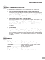
Precautions
● Do not expose the plug-in board to direct sunlight, excessive humidity, high temperatures, excessive dust or
strong vibrations.
● Before handling the plug-in board, be sure to touch a
metal surface to discharge any static electricity which
may be in your body.
● When holding the plug-in board, do not touch the inside area of the circuit board or apply excessive pressure to the board, and be sure to protect the board from
contact with water or other liquids.
● Before installing the plug-in board onto a tone generator/sound card, unplug the power connector of your computer.
● Before connecting the computer to other devices, turn
off the power switches of all devices.
● Yamaha is not responsible for loss of data through computer malfunctions or operator actions.
● The plug-in board contains no user-serviceable parts,
so never touch the inside area of the circuit board or
tamper with the electronic circuitry in any way. Doing
so may result in electrical shock or damage to the plugin board.
YAMAHA CANNOT BE HELD RESPONSIBLE
FOR DAMAGE CAUSED BY IMPROPER
CARE AND USE OF THE PLUG-IN BOARD.
* The company names and product names in this Owner’s Manual are the trademarks or registered trademarks of their respective companies.
* The screens as illustrated in this owner’s manual are for instructional purposes only, and may
appear somewhat different from the ones of your instrument.
FCC INFORMATION (U.S.A.)
1. IMPORTANT NOTICE: DO NOT MODIFY THIS UNIT!
This product, when installed as indicated in the instructions contained in this manual, meets FCC requirements. Modifications
not expressly approved by Yamaha may void your authority, granted by the FCC, to use the product.
2. IMPORTANT: When connecting this product to accessories and/or another product use only high quality shielded cables.
Cable/s supplied with this product MUST be used. Follow all installation instructions. Failure to follow instructions could void
your FCC authorization to use this product in the USA.
3. NOTE: This product has been tested and found to comply with the requirements listed in FCC Regulations, Part 15 for Class
”B” digital devices. Compliance with these requirements provides a reasonable level of assurance that your use of this product
in a residential environment will not result in harmful interference with other electronic devices. This equipment generates/
uses radio frequencies and, if not installed and used according to the instructions found in the users manual, may cause
interference harmful to the operation of other electronic devices. Compliance with FCC regulations does not guarantee that
interference will not occur in all installations. If this product is found to be the source of interference, which can be determined
by turning the unit ”OFF” and ”ON”, please try to eliminate the problem by using one of the following measures:
Relocate either this product or the device that is being affected by the interference.
Utilize power outlets that are on different branch (circuit breaker or fuse) circuits or install AC line filter/s.
In the case of radio or TV interference, relocate/reorient the antenna. If the antenna lead-in is 300 ohm ribbon lead, change
the lead-in to co-axial type cable.
If these corrective measures do not produce satisfactory results, please contact the local retailer authorized to distribute this
type of product. If you can not locate the appropriate, please contact Yamaha Corporation of America, Electronic Service
Division, 6600 Orangethorpe Ave, Buena Park, CA 90620
* This applies only to products distributed by YAMAHA CORPORATION OF AMERICA.
CANADA
This Class B digital apparatus complies with Canadian ICES-003.
Cet appareil numérique de la classe B est conforme à la norme NMB-003 du Canada.
• This applies only to products distributed by Yamaha Canada Music Ltd.
• Ceci ne s’applique qu’aux produits distribués par Yamaha Canada Musique Ltée.
2
Introduction
Congratulations and thank you for purchasing the Yamaha PLG100-VH Vocal Harmony Plug-in Board!
The PLG100-VH is designed for use with the MU128 Tone Generator (as well as other MU-series
instruments and the SW1000XG PCI Audio/MIDI Card), providing automatic and authentic sounding
vocal harmony effects. It takes the sound of your voice (via a microphone and one of the A/D inputs)
and reproduces it as a harmony vocal — providing up to four-part harmonies, including your original
voice. The actual harmony notes can be controlled from a MIDI keyboard or sequencer, allowing you
to perfectly match the harmony to chord changes.
The settings and parameters of the PLG100-VH can also be conveniently edited with a Windows PC
computer by using the VH Effect Editor software module (included in the XGworks Music Sequencer
software).
Table of Contents
4
Harmony Parameters ................................................ 12
Overview of the PLG100-VH ...................................... 4
Installing the PLG100-VH ........................................... 4
Included Items ............................................................. 4
Required and Recommended Items ......................... 5
Specifications ............................................................. 5
Troubleshooting .......................................................... 6
Harmony Type ........................................................... 12
Vocoder Harmony Parameters ................................. 13
Chordal Harmony Parameters ................................. 19
Detune Harmony Parameters ................................... 21
Chromatic Harmony Prameters ............................... 22
About the PLG100-VH ...............................................
Effect Connection and Harmony Types ................. 7
Demonstration ............................................................... 7
Using the Harmony Effect .......................................... 8
Operation ..................................................................... 8
Harmony System Parameters ................................. 24
Appendix ....................................................................... 25
XG Effect Map ........................................................... 25
MIDI Data Format ...................................................... 26
MIDI Implementation Chart ...................................... 30
About the VH Effect Editor in XGworks ............. 11
Opening the VH Effect Editor ................................... 11
About XG Plug-in System
With Yamaha XG Plug-in System you can expand your tone generation system by simply mounting
an optional board onto the “mother” tone generator/sound card. For example, you will be able to use
extra voices from a different sound synthesis such as Virtual Acoustic Synthesis, apply completely
new dimensional facet of effects to your music and/or add the latest technology to your music.
About VH-XG
This XG Plug-in Board produces automatic harmony effects for vocals (via a microphone and the A/
D inputs). It features four harmony effect types, and allows you to control the harmony notes by
playing notes or chords on a MIDI keyboard. It also allows you to control the harmony automatically by note or chord data recorded to a sequencer. Other features include a gender changer for
changing the input voice between male and female, and detuning for a natural chorus effect.
3
About the PLG100-VH
Overview of the PLG100-VH
The PLG100-VH provides a sophisticated harmony effect that takes the sound of your
voice (via a microphone and the A/D inputs) and reproduces it as a harmony vocal, providing up to four-part harmonies (including your original voice).
Once it is connected, the PLG100-VH automatically becomes another effect block (Harmony) in the tone generator/sound card, and can be applied to one of the Parts. Although
Harmony can be applied to normal instrument Parts, it is designed specifically to work
with the A/D inputs.
You can pre-program the pitch interval of the harmony, or you can “play” the harmony
from your connected MIDI keyboard (or sequencer), and even have the harmony interval
change, depending on the chord you play. As long as your own voice is in pitch and you
play the appropriate chords, the PLG100-VH ensures that the harmony “voices” will be
enharmonically correct and stay in pitch with the chord changes of the song. It also includes a “gender changer” effect that turns a male voice into a female voice (or vice versa),
and a vibrato effect that automatically adds a warm, natural vibrato to your voice.
Installing the PLG100-VH
For detailed instructions on installing the PLG100-VH, refer to the owner’s manual of the
XG-Plug-in-compatible “mother” device (e.g., MU128, SW1000XG, etc.).
Included Items
The following items have been included in the package of your new PLG100-VH. Please
make sure that you have them all before starting to setup and use the instrument. If an item
is missing, contact the store or dealer from which you purchased the PLG100-VH.
• PLG100-VH board
• PLG100-VH Owner’s Manual (this book)
• CD-ROM disc “XGtools”
4
About the PLG100-VH
Required and Recommended Items
In addition to the included items listed above, you should also have the following:
• An XG tone generator/sound card compatible with the XG Plug-in System
In order to use the PLG100-VH, you’ll need an XG tone generator or sound card that is
compatible with the XG Plug-in System. Compatible instruments include the MU128,
MU100, and the SW1000XG. The tone generator/sound card should also have an available slot or space for installing the PLG100-VH.
• XGworks or XGworks lite Music Sequencing Software
These software sequencers provide convenient tools for taking full advantage of the
PLG100-VH, letting you create song data that automatically controls the harmony effect during playback. They also include the powerful VH Effect Editor (see below) for
editing the harmony effect. XGworks lite is contained on a CD-ROM included with the
MU128 and MU100, and XGworks is contained on a CD-ROM included with the
SW1000XG.
• VH Effect Editor
This is a special plug-in software module for XGworks and XGworks lite. It gives you
comprehensive control over all PLG100-VH settings and parameters, including “hidden” parameters not available from the front panel of the tone generator. It also provides exceptionally easy and intuitive editing, with graphic controls and drag-and-drop
operations. It is contained on the CD-ROM included with the MU128, MU100, and
SW1000XG.
Specifications
Maximum harmony notes .......... 3
Effect Types ................................. 4 (Vocoder Harmony, Chordal Harmony,
Detune Harmony, Chromatic Harmony)
Voice controls .............................. Gender change (male → female, female → male),
Vibrato, Volume, Pan, Detune
Interface ....................................... XG Plug-in connector
Dimensions (W x D x H) ............ 138.5 x 89 x 8.5 mm
Weight .......................................... 53 g
Included accessories ................... Owner’s Manual, CD-ROM “XGtools”
5
About the PLG100-VH
Troubleshooting
If the harmony effect does not function properly or cannot be heard, check the following
points:
Is an appropriate XG tone generator/sound card connected to a sequencer
or computer?
• Refer to the relevant “Setting Up” instructions in the owner’s manual of the tone generator/sound card.
Is the HOST SELECT switch set properly?
• Refer to the relevant “Setting Up” instructions in the owner’s manual of the tone generator/sound card.
If you’re using a computer for playback, do you have the latest software
drivers and are their settings appropriate?
• Refer to the relevant instructions in the owner’s manual(s) of the particular software.
Is the PLG100-VH board connected properly?
• Refer to the board installation instructions in the owner’s manual of the tone generator/
sound card.
6
Effect Connection and Harmony Types
The PLG100-VH functions as an Insertion effect as the following illustration.
The bold lines are stereo lines.
Insertion1 is valid for
only one part.
insertion1 part
Insertion2 is valid for
only one part.
insertion2 part
VH insertion is valid for
only one part.
VH insertion part
Variation is valid for
only one part.
variation part
dry
INS1
INS2
VAR
PLG100-VH
reverb reverb
pan
return
rev send
part A1
insertion1on/off
insertion2 on/off
VH insertion on/off
REVERB
cho send
variation on/off
PAN
dry
INS1
INS2
VAR
PLG100-VH
rev send
part A2
insertion1on/off
insertion2 on/off
VH insertion on/off
variation on/off
cho send
send chorus to reverb
dry
INS1
part 1
insertion1on/off
INS2
insertion2 on/off
VAR
PLG100-VH
VH insertion on/off
variation on/off
rev send
cho send
CHORUS
PAN
chorus chorus
return
pan
OUT
EQ
dry
INS1
INS2
VAR
PLG100-VH
rev send
part 32
insertion1on/off
insertion2 on/off
VH insertion on/off
variation on/off
cho send
DRY LINE
The Harmony effect features four separate types: Vocoder, Chordal, Detune, and Chromatic.
Vocoder
This type produces up to three harmony notes, corresponding to the notes you play on
a connected MIDI keyboard. In other words, you can sing the melody and “play” the
harmony or harmonies from the keyboard, or you can have the harmonies automatically generated by song data on a sequencer. (Page 13)
Chordal
This type produces up to three harmony notes that correspond to the chords you play
on a connected MIDI keyboard (or chords recorded to a sequencer). Thirty-four
different chord types are recognized in this mode. (Page 19)
Detune
This type produces a slightly “detuned” pitch and mixes it with the input signal for a
rich chorusing effect. (Page 21)
Chromatic
This type produces a harmony at a predetermined, fixed pitch interval from the original sound (such as an octave, or a third). (Page 22)
Demonstration
The included CD-ROM contains the following demonstration songs:
1. AMAZING.MID
Amazing Grace
2. JINGLE.MID
Jingle Bells
The Effect Type is set to Vocoder Harmony for these demonstration songs.
To setup the MU128 for demonstration play, connect the microphone to one of A/D INPUT jacks.
To setup the SW1000XG, connect the microphone to the External Audio Input terminal.
7
Using the Harmony Effect
This section guides you through the steps of setting up and using the Harmony effect. Since the
PLG100-VH functions as an Insertion effect, it can be edited in the same fashion as the other
Insertion effects in the XG tone generator.
• Keep in mind that actual operation procedures may differ depending on which XG device you are using, the
MU128 or SW1000XG. In general, the instructions below assume you are using the MU128. On the whole, these
instructions are also applicable to the SW1000XG; however, since the SW1000XG has no panel controls, you’ll
need to use the corresponding software controls in the XGworks software. For specific operating instructions on
either the MU128 or SW1000XG, refer to the corresponding owner’s manual.
• When the Performance (PFM) mode is selected, the effect settings change when a different Performance number
is selected. To avoid this, make sure to store the Performance after editing. (Performance is not available on the
SW1000XG.)
Operation
Z Set up the MIDI keyboard or sequencer.
Do this if you wish to control the Harmony effect from a MIDI keyboard or with song
data played on a MIDI sequencer.
To do this:
1) Connect the MIDI device.
If the tone generator features both MIDI IN-A and B ports, connect the MIDI
device to the A port.
CONTROLLER
NUMBER LIST
B
SONG
SELECT
TIME SIGNATURE
TOP
BOTTOM MEASURE
SEQUENCER
STOP
CONTINUE
START
VOICE
MAP
POLY/
MONO
RESET SOUND OFF TG300B
CONTROL ALL CH RESET
BANK PROGRAM
SELECT CHANGE
CHANNEL DEVICE TOUCH
MERGE NUMBER SENSITIVITY
RESET
PROGRAM
TEMPO
GM
ON
SOUND
OFF
SYSTEM
XG
ON
MERGE
ON/OFF
MIDI
CH
FIXED
VELOCITY
RPN CONTROLLER NRPN
DATA
DENSITY
WHEEL ASSIGN
RPN CONTROLLER NRPN
MSB 1ST/ FOOT SW
LSB 1ST ASSIGN
TRANSPOSE
DRUM
NUMBER
PB
DATA
DENSITY DENSITY
CONTROL CHANGE
1 MODULATION
2 BREATH
5 PORTA TIME
6 DATA ENTRY
7 VOLUME
10 PANPOT
SLIDER ASSIGN
RPN CONTROLLER NRPN
DRUM
NUMBER
B
11
64
65
71
72
73
74
84
1
OTHERS
NRPN
EXPRESSION
HOLD1(DAMPER)
PORTAMENTO
HARMONIC
RELEASE TIME
ATTACK TIME
BRIGHTNESS
PORTA CTRL
2
91
93
94
REVERB
CHORUS
VARIATION
123 VIBRATO RATE
124 VIBRATO DEPTH
125 VIBRATO DELAY
126 LP FILTER CUTOFF
127 LP FILTER RESONANCE
128 HP FILTER CUTOFF
129 EQ LO GAIN
130 EQ HI GAIN
RPN
120 PB SENSITIVITY
121 FINE TUNE
122 COARSE TUNE
3
4
5
6
7
131 EQ LO FREQUENCY
132 EQ HI FREQUENCY
133 EG ATTACK TIME
134 EG DECAY TIME
135 EG RELEASE TIME
136 DRUM LP FILTER CUTOFF
137 DRUM LP FILTER RESONANCE
138 DRUM EG ATTACK RATE
8
9
A
B
139 DRUM EG DECAY RATE
140 DRUM PITCH COARSE
141 DRUM PITCH FINE
142 DRUM LEVEL
143 DRUM PAN
144 DRUM REVERB
145 DRUM CHORUS
146 DRUM VARIATION
C
D
E
147 DRUM HP FILTER CUTOFF
148 DRUM EQ LO GAIN
149 DRUM EQ HI GAIN
150 DRUM EQ LO FREQUENCY
151 DRUM EQ HI FREQUENCY
152 CH PRESSURE
153 KEY PRESSURE
154 MASTER VOLUME
156 MASTER TUNING
157 VELOCITY
158 TEMPO
ENTER
F
0
HEXA
DECIMAL
DECIMAL
MIDI
OUT
TONE GENERATOR
MUTE/
SOLO
PART
PART
UTIL EFFECT
ENTER
A/D INPUT
XG
TG300B
PERFORM
2
Keyboard or sequencer.
ALL
PLAY EDIT
1
MIDI
IN-A
STAND BY
ON
VOLUME
MIDI IN A
Piano
MODE
SELECT SELECT
EQ
EXIT
VALUE
VALUE
PART
BANK/PGM
VOL EXP PAN REV CHO VAR KEY
Chrom.perc.
Organ
Guitar
Bass
Strings
Ensemble
Brass
Reed
Pipe
Synth lead Synth pad
Synth effects
Ethnic
Percussive
SFX
Model excl.
SELECT PART GROUP
Drum
PHONES
MU PLG-1 PLG-2 PLG-3
MU128 or SW1000XG
2) Set the device’s MIDI transmit channel to 1 (or to the same channel you’ll be
setting in step #3 below).
• When the Harmony Type is set to Detune or Chromatic (pages 21~23), Harmony is unaffected by
a connected MIDI device.
HINT
• If you are using a sequencer to control the Harmony effect, dedicate one track of the song data
for control purposes, and set this to a MIDI channel different from all other tracks. (This channel setting should be matched in step #3 below.)
• Also, you’ll want to make sure that the connected keyboard or sequencer doesn’t sound any of the
MU128’s Parts. If one or more Parts are set to the same MIDI channel (as set above), change the
MIDI channel setting of the Part(s), or set the volume of the Part(s) to 0, or mute the Part(s).
X Set up the A/D Part on the MU128 or SW1000XG.
To do this:
1) Connect a microphone to the A/D INPUT jack (INPUT 1 on the MU128).
2) Select Part “A/D1,” then select the “Mic” preset (bank #000, program #002).
8
Using the Harmony Effect
C Set the Harmony Channel (Utility mode).
This determines the MIDI receive channel for the Harmony effect, and should be set to
the same value as set for the MIDI device in step #1 above. Harmony Channel is set in
the Utility mode. (For more information on the Utility mode and its parameters, see
page 24.)
To do this:
1) Select the Utility mode. (Press the [UTIL] button.)
2) Select the “PLUGIN” menu. (Use the [SELECT
[ENTER] button.)
/ ] buttons, and press the
3) Select the “PLG100-VH” (Harmony) menu. (Use the [SELECT
press the [ENTER] button.)
] button, and
4) Set the Harmony Channel value to 1.
Use the [SELECT ] button if necessary to select “Harmony Ch” (Harmony
Channel), then use the [VALUE / ] buttons to set the value to “01” (or the
same value as the transmit channel of the connected MIDI device).
V Assign the Harmony effect to the desired Part (in the Harmony Edit menu).
To do this:
1) Select the Effect menus. (Press the [EFFECT] button.)
9
Using the Harmony Effect
2) Select the “PLG” menu. (Use the [SELECT
the [ENTER] button.)
] button if necessary, and press
3) At the “PLG100-VH” (Harmony) menu, press [ENTER] again.
4) Assign the Insert Part parameter to the desired A/D Input.
Use the [SELECT ] button to select “Ins Part” (Insert Part), then use the
[VALUE / ] buttons to set the value to “AD01” (Input 1) as needed.
B Set the Harmony Type.
While still in the Harmony Edit menu, select the “Type” parameter (with the [SELECT ] button), then use the [VALUE / ] buttons to set the type: Vocoder,
Chordal, Detune, or Chromatic.
When set to Vocoder or Chordal, the notes or chords you play on the connected MIDI
keyboard determine the notes of the Harmony effect.
N Make other settings in the Harmony Edit menu as needed.
Select the desired parameter (with the [SELECT
/ ] buttons to change the value.
/ ] buttons), then use the [VALUE
Each Harmony Type has a different set of parameters. For a list of the parameters in
each type, see the following pages:
Vocoder ....................... page 13
Chordal ........................ page 19
Detune ......................... page 21
Chromatic .................... page 22
10
About the VH Effect Editor in XGworks
All of the settings and parameters of the PLG100-VH can be easily edited from a computer by
using the VH Effect Editor software module (included in the optional XGworks or XGworks lite
Music Sequencer software).
The VH Effect Editor gives you convenient at-a-glance view of all Harmony effect parameters,
and lets you easily edit them by typing in values on the computer keyboard or dragging the mouse.
It also gives you access to the “hidden” parameters, not controllable from the MU128 itself. Moreover, the VH Effect Editor provides an “Easy Setup” control that automatically makes the necessary settings for using the A/D input and the Harmony effect. Since the VH Effect Editor is
integrated into the XGworks/XGworks lite sequencer, you can easily automate the Harmony effect changes with your recorded songs.
Opening the VH Effect Editor
To open the VH Effect Editor, select “Plug-in” from the menu bar, then select “VH Effect
Editor” from the pull-down menu. If the VH Effect Editor is not properly installed to
XGworks, the VH Effect Editor menu item and the program itself will not be available.
For detailed instructions on using the VH Effect Editor, refer to the online Help messages
in the program itself.
• XGworks/XGworks lite requires an IBM-PC/AT compatible computer (100MHz or higher; Pentium
processor of 75Mhz or higher is recommended), 16MB RAM or more, running Windows 95 or Windows 98.
11
Harmony Parameters
Path [EFFECT] button → “PLG” → “PLG100-VH”
These parameters control the Harmony effect. Other Harmony parameters not included in this section are set in the System section (page
24). For general information on the Harmony effect and how to use it,
see page 8.
Since the available parameters depend on which Harmony Type is selected, separate parameter charts are given for each of the four types:
Vocoder, Chordal, Detune, and Chromatic.
Hidden Parameters
Some of the Harmony parameters are “hidden” parameters, and
cannot be edited from the panel of the MU128. However, they
can be edited with the VH Effect Editor in the optional XGworks
software. (Page 11)
Harmony Type
Settings:
THRU
VOCODER HM
CHORDAL HM
DETUNE HM
CHROMAT.HM (Chromatic)
When the Type is set to THRU, no Harmony effect is applied, and the only other available
parameter is Insert Part.
• The available parameters depend on the selected Harmony Type.
12
Harmony Parameters
Vocoder Harmony Parameters
The Vocoder type produces up to three harmony notes whose pitches correspond to the
notes you play on a connected MIDI keyboard. In other words, you can sing the melody
and “play” the harmony or harmonies from the keyboard (or from a sequencer). The
Harmony sound can also be transposed (see the Mode parameter below).
• When more than four MIDI notes are received, priority is given first to the most recently played notes,
then the highest notes. (In other words, the harmonies of lower notes and earlier notes are cut off.)
HINT
The Vocoder Type is best suited when:
• You want to determine the precise harmony notes yourself, including their octave register and whether
they are above or below the original melody note.
• You want to use harmony notes and voicings that fall outside the standard chords available in the
Chordal type (below).
• You can play the harmony part on the keyboard, or have it played on a sequencer.
• You want to precisely control how the harmony note or notes change pitch around a fixed melody pitch.
■ Parameter List .................................................................................
No. Parameter
1
Mode
2
3
4
5
6
7
8
9
10
Harmony Gender Type
Lead Gender Type
Lead Gender Depth
Lead Pitch Correction
Auto Upper Gender Threshold
Auto Lower Gender Threshold
Upper Gender Depth
Lower Gender Depth
Lead/Harmony
Display
1: no trans,
2: auto trans
3: -3 oct trns,
4: -2 oct trns
5: -1 oct trns,
6: +1 oct trns
7: +2 oct trns,
8: +3 oct trns
off, auto
off, unis, male, fem.
-64 — +63
off, on
0 — 12
0 — 12
-64 — +63
-64 — +63
L63>H — (L=H) — L<H63
11
12
13
14
Vibrato Depth
Vibrato Rate
Vibrato Delay
Insertion Part
0 — 127
0 — 127
0 — 127
off, 1 — 64, AD1 — AD64
Value
0—7
Default value
0
0—1
0—3
0 — 127
0—1
0 — 12
0 — 12
0 — 127
0 — 127
1 — 127
0
0
64
0
1
1
84
44
64
0 — 127
0 — 127
0 — 127
0 — 127
39
47
0
127
13
Harmony Parameters
■ Parameter Descriptions ..................................................................
1. Mode
• no trans
No transposition. The harmony notes correspond exactly to the pitch of the incoming
MIDI notes.
• auto trans
Automatic transposition of the harmony notes. This keeps the harmony notes close
(around the same octave register; ±600 cents) to the input signal, no matter which
octave the MIDI notes are played. For example, if your vocal is at a pitch of C3,
playing an E note anywhere on the connected MIDI keyboard results in a harmony
note of E3.
• -3oct trns — +3oct trns
Octave transposition. This fixes the octave transposition of the harmony notes, selectable in octaves from 3 octaves below (-) to 3 octaves above (+).
• When using the “auto trans” setting, some of the harmony notes may play in unexpected registers. To avoid this, change the mode to a setting other than “auto trans.”
2. Harmony Gender Type (H.GendrTyp)
Settings: off, Auto
This automatically determines the gender of the harmony notes (relative to the actual
gender of the singer).
• off
This turns off the gender change effect for the harmony notes.
• Auto
For this setting, the PLG100-VH “listens” to the pitch of your voice to determine
your gender, and automatically selects the opposite gender for the harmony notes.
Keep in mind that the gender change effect may vary according to the quality, character and pitch of the actual voice.
When “Auto” is set, the following parameters affect the operation of the gender change
effect: Auto Upper Gender Threshold, Auto Lower Gender Threshold, Upper Gender
Depth, and Lower Gender Depth.
14
Harmony Parameters
3. Lead Gender Type (L.GendrTyp)
Settings: off, unis (unison), male, fem. (female)
The PLG100-VH also produces a “lead” voice sound that can be mixed with harmony notes. These settings determine whether the gender of the lead voice can be
changed or not. It also lets you set the gender. When this is set to “off,” the gender of
the lead voice cannot be changed. When this is set to “unis” (unison), the lead voice
is reproduced at the same pitch as the voice; however, the gender can be changed by
using the Lead Gender Depth parameter below. The “male” and “fem.” (female)
settings reproduce the voice with the respective male or female vocal qualities. (To
finely adjust the quality of the lead voice, use the Lead Gender Depth parameter
below.)
• When Lead Gender Type is set to “unis,” “male,” or “fem.,” the amount of harmony notes is
reduced from three to two.
About the Lead and Harmony Voices
The PLG100-VH also produces a “lead” voice sound that can be mixed with the automatically produced harmony voices.
The PLG100-VH in effect “copies” your actual voice to create the lead voice. The lead voice then can
be altered both in pitch and gender, just as with the harmony voices.
To properly use the lead voice, make sure to set the following parameters:
Lead Gender Type .................. “unis,” “male,” or “fem.”
Lead Gender Depth ................ Set to desired/appropriate value.
Lead/Harmony Balance .......... Set to desired/appropriate value.
(For values at or near the maximum of “L<H63,” lead may not
sound.)
You can control the pitch of the lead voice separately from the harmonies. One useful application
would be to have melody and harmony data on different tracks/MIDI channels of sequencer song data
— the melody track would control the pitch of the lead voice, while the harmony track would control the
harmonies. This would ensure that all vocal parts stay in tune with each other and with the song —
even if your actual singing is slightly off pitch!
To control the pitch of the lead voice from a connected MIDI keyboard or sequencer (separate from the
harmonies), make the following settings:
Pitch Correction ..................... “on”
Melody Channel (page 24) ..... Set to same channel as the MIDI device. (Match this to the melody
track of the song data.)
Harmony Channel (page 24) .. Set to different value from Melody Channel.
(Match this to the harmony track of the song data.)
15
Harmony Parameters
4. Lead Gender Depth (L.GendrDpt)
Range: -64 — +63
This determines the quality or character of the lead voice, and depends on the setting
made in Lead Gender Type above. (This parameter has no effect when Lead Gender
Type is set to “off.”) Extreme negative or positive values result in pronounced distortion of the voice quality. Also, the effect may vary according to the quality, character
and pitch of the actual voice. Experiment with this to find values that sound most
natural (or unnatural, if you prefer).
5. Lead Pitch Correction (PchCorrect)
Settings: off, on
This determines whether the pitch of the lead voice is controlled by MIDI note data or
not. When this parameter and Lead Gender are set to “on,” the pitch of the lead voice
is “corrected” to the pitch of the received MIDI note.
• The Pitch Correction parameter is not available when Harmony Type is set to Detune. Also, this
parameter has no effect when Lead Gender Type is set to “off.”
6. Auto Upper Gender Threshold (Not selectable from MU128 panel controls.)
Range: 0 - 12 (semitones)
This determines which harmony notes above the melody will be gender-transformed
when Harmony Gender Type is set to “Auto.” More specifically, it sets the range or
interval of unchanged harmonies. When set to “0,” the gender of all harmony notes
above the melody will be changed. When set to another value, any harmonies within
the interval specified will not be changed.
For example, when this is set to 7 semitones, any harmonies a perfect fifth or lower
will remain at the same gender as the original vocal.
Melody note
Auto Upper Gender Threshold (set to 7)
Harmonies in this range are
left unchanged as to gender.
Harmonies in this range
change gender.
Used with Auto Lower Gender Threshold below, this gives you flexible control over
the gender of the harmony notes, both above and below the melody.
• This parameter has no effect when Harmony Gender Type is set to “off.”
16
Harmony Parameters
7. Auto Lower Gender Threshold (Not selectable from MU128 panel controls.)
Range: 0 - 12 (semitones)
This determines which harmony notes below the melody will be gender-transformed
when Harmony Gender Type is set to “Auto.” More specifically, it sets the range or
interval of unchanged harmonies. When set to “0,” the gender of all harmony notes
below the melody will be changed. When set to another value, any harmonies within
the interval specified will not be changed. For example, when this is set to 5 semitones,
any harmonies higher than a fourth below remain at the same gender as the original
vocal.
Melody note
Auto Lower Gender Threshold (set to 5)
Harmonies in this range
change gender.
Harmonies in this range are
left unchanged as to gender.
Used with Auto Upper Gender Threshold above, this gives you flexible control over
the gender of the harmony notes, both above and below the melody.
• This parameter has no effect when Harmony Gender Type is set to “off.”
8. Upper Gender Depth (Not selectable from MU128 panel controls.)
Range: -64 — +63
This determines the quality or character of the harmony notes above the melody that
are set to automatically change gender — according to the Harmony Gender Type
and Auto Upper Gender Threshold settings.
Extreme negative or positive values result in pronounced distortion of the voice quality. Also, the effect may vary according to the quality, character and pitch of the
actual voice. Experiment with this to find values that sound most natural (or unnatural, if you prefer).
• This parameter has no effect when Harmony Gender Type is set to “off.”
9. Lower Gender Depth (Not selectable from MU128 panel controls.)
Range: -64 — +63
This determines the quality or character of the harmony notes below the melody that
are set to automatically change gender — according to the Harmony Gender Type
and Auto Lower Gender Threshold settings.
Extreme negative or positive values result in pronounced distortion of the voice quality. Also, the effect may vary according to the quality, character and pitch of the
actual voice. Experiment with this to find values that sound most natural (or unnatural, if you prefer).
• This parameter has no effect when Harmony Gender Type is set to “off.”
17
Harmony Parameters
10. Lead/Harmony Balance (Lead/Harm)
Range: L63>H (maximum lead level) — L=H (equal level) —
L<H63 (maximum harmony level)
This determines the relative balance of the lead and harmony voices. For most conventional applications, this should be set to “L=H” or a slightly higher lead level
(such as “L10>H” or more).
11. Vibrato Depth (Not selectable from MU128 panel controls.)
Range: 0 — 127
This determines the depth of the Vibrato effect on the harmony notes and the lead
note. (The lead note is not affected when Lead Gender Type is set to “off.”) Higher
values result in a stronger, more pronounced vibrato sound.
12. Vibrato Rate (Not selectable from MU128 panel controls.)
Range: 0 — 127
This determines the speed of the Vibrato effect on the harmony notes and the lead
note. (The lead note is not affected when Lead Gender Type is set to “off.”) Higher
values result in a faster vibrato sound.
13. Vibrato Delay (Not selectable from MU128 panel controls.)
Range: 0 — 127
This determines the amount of delay in the onset of the Vibrato effect on the harmony
notes and the lead note. (The lead note is not affected when Lead Gender Type is set
to “off.”) Singers often employ a delayed vibrato as they hold notes; this parameter is
designed to reproduce that effect, and helps to create a more natural, lifelike sound.
Higher values result in a longer delay time.
14. Ins (Insertion) Part
Settings: off, 1 — 64, AD1 — AD64
This determines the Part to which the Harmony effect is applied. For example, to
apply Harmony to a microphone input through A/D INPUT 1, set this to “AD01”.
When set to “off,” the Harmony effect is cancelled.
• Depending on the particular tone generator or sound card you are using, the actual range of this
parameter may differ from that given above.
• On the VH Editor software, the number of selectable Parts in this parameter exceeds the actual
amount available on the MU128 and the SW1000XG. The software parameter has these values to
accommodate the expanded capacity of other tone generators and boards.
18
Harmony Parameters
Chordal Harmony Parameters
The Chordal type produces up to three harmony notes that correspond to the chords you
play on a connected MIDI keyboard (or chords recorded to a sequencer). For example, if
you play a C major triad on the keyboard (with Chordal Mode set to “trio”) and sing a C
note, the resulting harmonies will be C, E, and G. Thirty-four different chord types are
recognized in this mode (see list below), giving you an amazingly full and flexible palette
of harmonies, suitable for nearly any music style. The number of harmonies produced and
their position above or below the melody is set in the Mode parameter (page 20).
• In general, the Chordal Type is best suited when you want to simply play the chords and have the
Harmony effect automatically sort out the suitable notes.
Chords Recognized in Chordal Type
C
C#
D
D#
E
F
F#
G
G#
A
A#
B
Maj
Maj6
Maj7
Maj7(#11)
Maj(9)
Maj7 (9)
Maj6(9)
aug
min
min6
min7
min7b5
min(9)
min7(9)
min7(11)
minMaj7
minMaj7(9)
dim
dim7
7th
7sus4
7b5
7(9)
7(#11)
7(13)
7(b9)
7(b13)
7(#9)
Maj7aug
7aug
1+8
1+5
sus4
1+2+5
■ Parameter List .................................................................................
No. Parameter
1
Mode
2
3
4
5
6
7
8
9
10
Harmony Gender Type
Lead Gender Type
Lead Gender Depth
Lead Pitch Correction
Auto Upper Gender Threshold
Auto Lower Gender Threshold
Upper Gender Depth
Lower Gender Depth
Lead/Harmony
Display
1: duet above
2: duet below
3: duet abv+b
4: trio above
5: trio a&b
6: trio below
7: trio a&b+b
8: quar above
9: quar a&b
10: quar below
off, auto
off, unis, male, fem.
-64 — +63
off, on
0 — 12
0 — 12
-64 — +63
-64 — +63
L63>H — (L=H) — L<H63
11
12
13
14
Vibrato Depth
Vibrato Rate
Vibrato Delay
Insertion Part
0 — 127
0 — 127
0 — 127
off, 1 — 64, AD1 — AD64
Value
0—9
Default value
0
0—1
0—3
0 — 127
0—1
0 — 12
0 — 12
0 — 127
0 — 127
1 — 127
0
0
64
0
1
1
84
44
64
0 — 127
0 — 127
0 — 127
0 — 127
39
47
0
127
19
Harmony Parameters
■ Parameter Descriptions ..................................................................
1. Mode
• duet above
Produces one harmony note, in a pitch above the lead note.
• duet below
Produces one harmony note, in a pitch below the lead note.
• duet abv+b (duet above + bass)
Produces two harmony notes — one in a pitch above the lead note, and one an
octave below the other harmony. (The “+b” in the type name stands for “added
bass note.”)
• trio above
Produces two harmony notes, in pitches above the lead note.
• trio a&b (trio above + below)
Produces two harmony notes — one in a pitch above the lead note, and one below.
• trio below
Produces two harmony notes, in pitches below the lead note.
• trio a&b+b (trio above & below + bass)
Produces three harmony notes — one in a pitch above the lead note, and two below
— one of them an octave below the higher harmony. (The “+b” in the type name
stands for “added bass note.”)
• quar above (quartet above)
Produces three harmony notes, in pitches above the lead note.
• quar a&b (quartet above & below)
Produces three harmony notes — two in pitches above the lead note, and one below.
• quar below (quartet below)
Produces three harmony notes, in pitches below the lead note.
Other Parameters
The remaining parameters for the Chordal Type are the same as those for the Vocoder
Type, described on pages 14~18.
20
Harmony Parameters
Detune Harmony Parameters
The Detune type produces a slightly “detuned” pitch and mixes it with the input signal for
a rich chorusing effect. The amount of the detuning is set in the Mode parameter (below).
MIDI note data from a keyboard or sequencer has no effect in this type.
■ Parameter List .................................................................................
No. Parameter
1
Mode
2
3
4
5
6
7
8
9
10
11
12
13
14
Display
1: low
3: mid-high
2: mid-low
4: high
Value
0—3
Default value
0
Lead Gender Type
Lead Gender Depth
off, unis, male, fem.
-64 — +63
0—3
0 — 127
0
64
Lead/Harmony
L63>H — (L=H) — L<H63
1 — 127
64
Vibrato Depth
Vibrato Rate
Vibrato Delay
Insertion Part
0 — 127
0 — 127
0 — 127
off, 1 — 64, AD1 — AD64
0 — 127
0 — 127
0 — 127
0 — 127
39
47
0
127
■ Parameter Descriptions ..................................................................
1. Mode
• low
Detunes the pitch by ±7 cents (least amount of detuning).
• mid-low
Detunes the pitch by ±11 cents.
• mid-high
Detunes the pitch by ±15 cents.
• high
Detunes the pitch by ±20 cents (most amount of detuning).
• When Detune is selected, the following parameters are not available:
2. Harmony Gender Type
5. Lead Pitch Correction
6. Auto Upper Gender Threshold
7. Auto Lower Gender Threshold
8. Upper Gender Depth
9. Lower Gender Depth
Other Parameters
The remaining parameters for the Detune Type are the same as those for the Vocoder
Type, described on pages 14~18.
21
Harmony Parameters
Chromatic Harmony Parameters
The Chromatic type produces a harmony at a fixed pitch interval from the original sound
(such as an octave, or a third). The amount and direction of the pitch shift is set in the
Mode parameter (below). MIDI note data from a keyboard or sequencer has no effect in
this type.
■ Parameter List .................................................................................
No. Parameter
1
Mode
2
3
4
5
6
7
8
9
10
Harmony Gender Type
Lead Gender Type
Lead Gender Depth
Lead Pitch Correction
Auto Upper Gender Threshold
Auto Lower Gender Threshold
Upper Gender Depth
Lower Gender Depth
Lead/Harmony
Display
1: oct below
2: 3rd below
3: 5th below
4: unison
5: 3rd above
6: 5th above
7: oct above
off, auto
off, unis, male, fem.
-64 — +63
off, on
0 — 12
0 — 12
-64 — +63
-64 — +63
L63>H — (L=H) — L<H63
11
12
13
14
Vibrato Depth
Vibrato Rate
Vibrato Delay
Insertion Part
0 — 127
0 — 127
0 — 127
off, 1 — 64, AD1 — AD64
Value
0—6
Default value
0
0—1
0—3
0 — 127
0—1
0 — 12
0 — 12
0 — 127
0 — 127
1 — 127
0
0
64
0
1
1
84
44
64
0 — 127
0 — 127
0 — 127
0 — 127
39
47
0
127
■ Parameter Descriptions ..................................................................
1. Mode
• oct below
Produces a harmony note an octave below the input note.
• 3rd below
Produces a major third harmony note in the octave below the input note. (Harmony is transposed eight semitones down.)
• 5th below
Produces a perfect fifth harmony note in the octave below the input note. (Harmony is transposed five semitones down.)
22
Harmony Parameters
• unison
Produces a “harmony” note at the same pitch as the input note. (This can be clearly
distinguished from the original signal by changing the Harmony Gender Type; see
page 14.)
• 3rd above
Produces a major third harmony note in the same octave as the input note. (Harmony is transposed four semitones up.)
• 5th above
Produces a perfect fifth harmony note in the same octave as the input note. (Harmony is transposed seven semitones up.)
• oct above
Produces a harmony note an octave above the input note.
Other Parameters
The remaining parameters for the Chromatic Type are the same as those for the Vocoder Type, described on pages 14~18.
23
Harmony System Parameters
Path [UTILITY] button → “PLUGIN” → “PLG100-VH”
The System section of parameters provide a variety of additional settings for the
Harmony effect, including MIDI channel settings for the harmony and melody, as
well as independent volume, pan, and detune controls for each harmony note. For
general information on the Harmony effect and how to use it, see page 8.
Harmony Channel (Harmony Ch)
Settings: off, 1 - 16
This determines the MIDI channel over which the Harmony effect is controlled. For
example, when this is set to the same value as the MIDI transmit channel of a connected MIDI keyboard or sequencer, you can use that device to “play” harmonies.
(Page 8)
Harmony Mute (Not selectable from MU128 panel controls.)
Settings: Off, On
This determines whether the harmony notes are muted or not. For the harmony notes
to be heard, this should be set to “off.” To mute the harmony notes, set this to “on.”
This parameter is intended primarily for sequencer applications, letting you effectively turn the harmonies on and off as needed within a song.
Melody Channel (Melody Ch)
Settings: off, 1 - 16
This determines the MIDI channel over which the lead sound of the Harmony effect
is controlled. For example, when this is set to the same value as the MIDI transmit
channel of a connected MIDI keyboard or sequencer, you can use that device to
control the pitch of the lead sound. (See “About the Lead and Harmony Voices” on
page 15.)
Harmony 1 - 3 Volume (Not selectable from MU128 panel controls.)
Range: 0 — 127
This determines the volume of the selected harmony note (1, 2, or 3).
Harmony 1 - 3 Pan (Not selectable from MU128 panel controls.)
Settings: Random, -63 (full left) — 0 (center) — +63 (full right)
This determines the stereo position of the selected harmony note (1, 2, or 3). The
“Random” setting randomly assigns the selected harmony note to a pan position.
Harmony 1 - 3 Detune (Not selectable from MU128 panel controls.)
Range: -64 — +63
This determines the amount of detuning for the selected harmony note (1, 2, or 3). A
setting of “0” results in no detuning; positive and negative settings adjust the pitch of
the harmony note up or down, respectively.
24
Appendix
XG Effect Map
UNIQUE INSERTION EFFECT (HARMONY) TYPE
TYPE MSB
TYPE LSB
DEC HEX
00
01
000
0
THRU
:
:
:
088
58
THRU
089
59
VOCODER HARMONY
090
5A
CHORDAL HARMONY
091
5B
DETUNE HARMONY
092
5C
CHROMATIC HARMONY
093
5D
THRU
:
:
:
127
7F
THRU
02
...
08
THRU effect
same as BASIC EFFECT(LSB=0)
25
Appendix
MIDI Data Format
1. Channel Messages
1.1 Note on/note off
9n
kk
vv
note on message
For Vocoder harmony, used to specify the pitch to be sounded.
For Chordal harmony, used to detect chords.
note off message
8n
9n
kk
kk
n
kk
vv
vv
00
: MIDI channel
: note number
: velocity
Harmony ch
O
Melody ch
O
O
O
Velocity values are ignored.
For the Harmony channel, processing will be follows.
1) For Vocoder harmony, these messages will specify the pitch to be sounded.
2) For Chordal harmony, these messages are used to direct chords.
For Melody channel, these messages are received for the following purposes.
1) For Vocoder harmony, these messages are received as the basic pitch to control the gender of the harmony sound.
2) For Vocoder harmony, if Vocoder Mode is “Auto Transpose,” the basic pitch is received.
For both 1) and 2), if the Melody channel is off, the input audio will be the basic pitch.
3) When Lead Gender and Lead Pitch Correction are on the input pitch is shifted to the note-on pitch of the received note.
If the Melody channel is off, the pitch will be shifted to the nearest chromatic pitch.
1.2 Control changes
Bn cc vv
n
cc
vv
:
:
:
MIDI channel
control#
data
1.2.1 Data Entry
This message sets the value of the parameter that was specified by RPN (refer to 1.2.4) or NRPN (refer to 1.2.3).
Control#
6
Parameter
Data Entry MSB
Data Range
0...127
Harmony ch
O
Melody ch
O
Harmony ch
O
Melody ch
X
1.2.2 Hold1
This message controls sustain pedal on/off.
Control#
64
Parameter
Hold1
Data Range
0...63,64...127
(OFF , ON)
When ON, currently-sounding notes will be sustained even after note-off is received.
1.2.3 NRPN (Non-registered parameter number)
This message is used to set sound parameters such as vibrato or detune, etc.
The NRPN MSB and NRPN LSB specify the parameter which is to be controlled, and subsequently Data Entry (refer to 1.2.1) is used to set the value of
the specified parameter. Only the MSB of Data Entry is recognized.
Control#
98
99
Parameter
NRPN LSB
NRPN MSB
Data Range
0...127
0...127
The following NRPN messages are recognized.
NRPN
Data Entry
Parameter name and range of values
MSB LSB
MSB
00 00
mm
Harmony Mute
mm : 00 - 63 (off), 64 - 127 (on)
26
Harmony ch
O
Melody ch
O
Harmony ch
Melody ch
O
X
01
08
mm
Vibrato Rate Modulation
mm : 00 - 64 - 127 (0...127)
Melody channel is effective only when Gender is ON.
O
O
01
09
mm
Vibrato Depth Modulation
mm : 00 - 64 - 127 (0...127)
Melody channel is effective only when Gender is ON.
O
O
01
10
mm
Vibrato Delay Modulation
mm : 00 - 64 - 127 (0...127)
Melody channel is effective only when Gender is ON.
O
O
01
26
mm
Detune Modulation
mm : 00 - 127 (0...127)
Controls the overall amount of detune specified for the individual voice.
O
X
02
16
mm
02
17
mm
The following NRPN numbers independently control the volume of each harmony note.
The currently-sounding harmony notes are numbered sequentially beginning from the lowest note.
Harmony 1 Volume
O
mm : 00 - 127 (0...127)
Harmony 2 Volume
mm : 00 - 127 (0...127)
O
X
X
Appendix
02
18
mm
Harmony 3 Volume
mm : 00 - 127 (0...127)
O
X
The following NRPN numbers independently control the panning of each harmony note.
The currently-sounding harmony notes are numbered sequentially beginning from the lowest note.
When the value is 0, panning will be random.
For random panning with Vocoder harmony, the pan position will change at each key-on.
For random panning with Chordal harmony, the pan position will change whenever the chord changes.
For Detune and Chromatic harmony, random pan will not function, and the panning will be centered.
Harmony 1 Pan
O
X
mm : 00, 01 - 64 - 127 (random, Lch...center...Rch)
02
32
mm
02
33
mm
Harmony 2 Pan
mm : 00, 01 - 64 - 127 (random, Lch...center...Rch)
O
X
02
34
mm
Harmony 3 Pan
mm : 00, 01 - 64 - 127 (random, Lch...center...Rch)
O
X
The following NRPN numbers independently control the detune amount for each harmony sound.
The currently-sounding harmony notes are numbered sequentially beginning from the lowest note.
Harmony 1 Detune
O
mm : 00 - 64 - 127 (-64...0...+63)
X
02
48
mm
02
49
mm
Harmony 2 Detune
mm : 00 - 64 - 127 (-64...0...+63)
O
X
02
50
mm
Harmony 3 Detune
mm : 00 - 64 - 127 (-64...0...+63)
O
X
Harmony ch
Melody ch
O
O
1.2.4 RPN (Registered Parameter Number)
This message is used to set Pitch Bend Sensitivity.
RPN MSB and RPN LSB are used to specify the parameter which is to be controlled, and subsequently
Data Entry (refer to 1.2.1) is used to set the value of the specified parameter.
Only the MSB of Data Entry is recognized.
Control#
100
101
Parameter
RPN LSB
RPN MSB
Data Range
0...127
0...127
The following RPN numbers are recognized.
RPN
Data Entry
Parameter name and range of values
MSB LSB
MSB
00H 00H
mm
Pitch Bend Sensitivity
mm : 00 - 24 (0...24 semitones)
Settable in semitone steps over a two-octave range
7FH 7FH
RPN null
O
Set RPN and NRPN numbers to a condition in which no numbers have been specified.
Internal settings will not be affected.
—
O
1.2.5 All Note Off
For Vocoder harmony, this message turns off all currently-sounding harmony notes.
Control#
123
Parameter
All Note Off
Data Range
0
1.3 Pitch Bend
En
vv vv
n
:
MIDI channel
vv :
data
This message conveys operations of the pitch bender.
It will modify the pitch in the range specified by RPN Pitch Ben Sensitivity.
For the Melody channel, this message will have an effect only when Lead Gender is ON.
Harmony ch
O
Melody ch
O
2. System exclusive messages
2.1 GM system on
F0
7E
7F
09 01
F7
F0
7E
0n
09 01
F7
This message initializes the tone generator system.
All default values are restored.
n
:
device number
2.2 XG system on
F0
43
1n
4C 00
00
7E
00
This message initializes the tone generator system.
All default values are restored.
n
:
F7
device number
2.3 XG parameter change format
F0
43
1n
4C aa
aa
aa
dd
F7
This message sends and receives parameters from tables 1 and 2 as a single message unit (combines and sends/receives 2 byte parameters).
n
aa
dd
:
:
:
device number
address
data
27
Appendix
2.4
XG bulk dump format
F0
43
0n
4C bb
bb
aa
aa
aa
dd
...
dd
cc
F7
This message sends and receives parameters from tables 1 and 2 as independent blocks (parameters are combined as a TOTAL SIZE unit).
n
bb
aa
dd
cc
2.5
:
:
device number
address (only top of parameters in TABLE1 can be selected)
XG parameter request format
F0
43
3n
4C aa
aa
aa
F7
This message sends parameter changes after receiving a send request for a parameter unit from table 1.
n
aa
2.7
device number
byte count (dd...dd)
address (only top of parameters in TABLE1 and 2 can be selected)
data
check sum (Adds bb, aa, dd and cc which sets the resulting lower 7 bytes to 0.)
XG dump request format
F0
43
2n
4C aa
aa
aa
F7
This message sends a bulk dump in response to a send request for each parameter block from table 2 (parameters are combined as a TOTAL SIZE unit).
n
aa
2.6
:
:
:
:
:
:
:
device number
address
Chord control code
F0
43
7E
02 cr
ct
7F
7F
F7
For Chordal mode, this is used to specify the chord.
The chord can also be specified by Note-on messages.
cr
ct
: chord root (0fffnnnn)
fff : Accidental
0 : bbb
1 : bb
2 : b
3 : natural
4 : #
5 : ##
6 : ###
:
:
:
:
:
:
:
:
:
Note
reserved
C
D
E
F
G
A
B
: chord type
0 : Maj
1 : Maj6
2 : Maj7
3 : Maj7(#11)
4 : Maj(9)
5 : Maj7(9)
6 : Maj6(9)
7 : aug
8 : min
9 : min6
0A : min7
0B : min7b5
0C : min(9)
0D : min7(9)
0E : min7(11)
0F : minMaj7
10 : minMaj7(9)
11 : dim
12 : dim7
13 : 7th
14 : 7sus4
15 : 7b5
16 : 7(9)
17 : 7(#11)
18 : 7(13)
19 : 7(b9)
1A : 7(b13)
1B : 7(#9)
1C : Maj7aug
1D : 7aug
1E : 1+8
1F : 1+5
20 : sus4
21 : 1+2+5
22 : chord cancelSame processing as chord-off.
(Example) To specify Am7,
F0
43
7E 02
28
nnnn
0
1
2
3
4
5
6
7
36
(A)
0A
7F
(m7)
7F
F7
Appendix
TABLE1
XG PARAMETER CHANGE TABLE ( UNIQUE EFFECT)
Address
Size Data
Parameter
(H)
(H) (H)
04
n
00
2 00 - 7F
UNIQUE INSERTION EFFECT TYPE MSB
00 - 7F
UNIQUE INSERTION EFFECT TYPE LSB
02
1 00 - 7F
UNIQUE INSERTION EFFECT PARAMETER1
03
1 00 - 7F
UNIQUE INSERTION EFFECT PARAMETER2
04
1 00 - 7F
UNIQUE INSERTION EFFECT PARAMETER3
05
1 00 - 7F
UNIQUE INSERTION EFFECT PARAMETER4
06
1 00 - 7F
UNIQUE INSERTION EFFECT PARAMETER5
07
1 00 - 7F
UNIQUE INSERTION EFFECT PARAMETER6
08
1 00 - 7F
UNIQUE INSERTION EFFECT PARAMETER7
09
1 00 - 7F
UNIQUE INSERTION EFFECT PARAMETER8
0A
1 00 - 7F
UNIQUE INSERTION EFFECT PARAMETER9
0B
1 00 - 7F
UNIQUE INSERTION EFFECT PARAMETER10
0C
1 00 - 7F
UNIQUE INSERTION EFFECT PART
0D
0E
0F
10
11
TOTAL SIZE
04
n
Description
Default
Refer to XG EFFECT MAP
00 : basic type
Refer to Effect parameter list
Refer to Effect parameter list
Refer to Effect parameter list
Refer to Effect parameter list
Refer to Effect parameter list
Refer to Effect parameter list
Refer to Effect parameter list
Refer to Effect parameter list
Refer to Effect parameter list
Refer to Effect parameter list
Part1...64(0...63)
AD1...AD63(64...126)
OFF(127)
-64 - 63
-64 - 63
-64 - 63
-64 - 63
-64 - 63
59(=Vocoder harmony)
00
depends on type
depends on type
depends on type
depends on type
depends on type
depends on type
depends on type
depends on type
depends on type
depends on type
7F
40
40
40
40
40
1
1
1
1
1
12
00 - 7F
00 - 7F
00 - 7F
00 - 7F
00 - 7F
MW UNIQUE INSERTION CONTROL DEPTH
BEND UNIQUE INSERTION CONTROL DEPTH
CAT UNIQUE INSERTION CONTROL DEPTH
AC1 UNIQUE INSERTION CONTROL DEPTH
AC2 UNIQUE INSERTION CONTROL DEPTH
14
1
00 - 7F
7F
1
00 - 7F
UNIQUE INSERTION EFFECT EXTERNAL
CONTROL CH1(HARMONY CHANNEL)
UNIQUE INSERTION EFFECT EXTERNAL
CONTROL CH2 (MELODY CHANNEL)
1...16(0...15), off(127)
15
1...16(0...15), off(127)
7F
UNIQUE INSERTION EFFECT PARAMETER11
UNIQUE INSERTION EFFECT PARAMETER12
UNIQUE INSERTION EFFECT PARAMETER13
UNIQUE INSERTION EFFECT PARAMETER14
UNIQUE INSERTION EFFECT PARAMETER15
UNIQUE INSERTION EFFECT PARAMETER16
Refer to Effect parameter list
Refer to Effect parameter list
Refer to Effect parameter list
Refer to Effect parameter list
Refer to Effect parameter list
Refer to Effect parameter list
depends on type
depends on type
depends on type
depends on type
depends on type
depends on type
TOTAL SIZE
2
04
1
1
1
1
1
1
6
n
20
21
22
23
24
25
TOTAL SIZE
00 - 7F
00 - 7F
00 - 7F
00 - 7F
00 - 7F
00 - 7F
n : refers to a number used to recognize individual boards when multiple boards are installed.
n=0: board 1
n=1: board 2
INSERTION EFFECT TYPE MSB
: h’ 59=Vocoder harmony
: h’ 5A=Chordal harmony
: h’ 5B=Detune harmony
: h’ 5C=Chromatic harmony
For all other values, “Thru” will be selected and the input signal will be output as is.
MW INSERTION CONTROL DEPTH
BEND INSERTION CONTROL DEPTH
CAT INSERTION CONTROL DEPTH
AC1 INSERTION CONTROL DEPTH
AC2 INSERTION CONTROL DEPTH
: Not supported by this board
: Not supported by this board
: Not supported by this board
: Not supported by this board
: Not supported by this board
HARMONY CHANNEL
MELODY CHANNEL
: Controls the harmony
: Controls the melody as well as the gender setting for the harmony
TABLE2
XG PARAMETER CHANGE TABLE ( SYSTEM )
Address
Size Data
Parameter
(H)
(H) (H)
0
0
0
4 0000 - 07FF MASTER TUNE
1
2
3
4
5
6
TOTAL SIZE
1
1
1
7
00 - 7F
00 - 7F
28 - 58
MASTER VOLUME
MASTER ATTENUATOR
TRANSPOSE
Description
Default
-102.4 - +102.3[cent]
1st bit3-0mbit15-12
2nd bit3-0mbit11-8
3rd bit3-0mbit7-4
4th bit3-0mbit3-0
0 - 127
0 - 127
-24 - +24 [semitones]
00 04 00 00
7F
0
40
MASTER VOLUME and MASTER ATTENUATOR are not supported by this board.
They can be controlled through the plug-in platform.
29
30
Change
Control
6
64
98-99
100-101
Key's
Ch's
After
Touch
Pitch Bend
Note ON
Note OFF
x
x
x
x
x
x
x
x
x
x
: True voice **************
Velocity
Note
Number
x
x
Default
Messages
Altered
Mode
**************
x
x
Default
Changed
Basic
Channel
Transmitted
o
o
o
o
o 0-24 semi
x
x
x
x
0 - 127
0 - 127
3
x
x
off
1 - 16
Recognized
[ Vocal Harmony Plug-in Board ]
Model PLG100-VH MIDI Implementation Chart
Function...
YAMAHA
Data Entry
Hold1
NRPN LSB,MSB
RPN LSB,MSB
Remarks
Date :01-JUL-1998
Version : 1.1
Appendix
MIDI Implementation Chart
: True #
Mode 1 : OMNI ON , POLY
Mode 3 : OMNI OFF, POLY
All Sound Off
Reset All Cntrls
Local ON/OFF
All Notes OFF
Active Sense
Reset
x
x
x
x
x
x
:
:
:
:
Mes- :
sages:
Notes:
Aux
x
x
x
x
x
: Song Pos.
: Song Sel.
: Tune
o
x
x
x
o(123)
x
x
x
x
x
x
x
o
x
Mode 2 : OMNI ON ,MONO
Mode 4 : OMNI OFF,MONO
x
**************
System
: Clock
Real Time: Commands
Common
System Exclusive
Prog
Change
o : Yes
x : No
Appendix
31