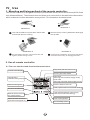
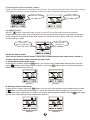
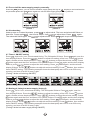
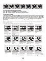
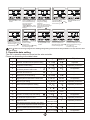
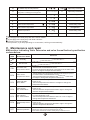
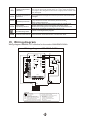
1
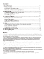
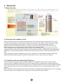
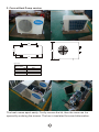
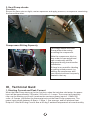
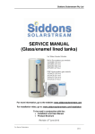
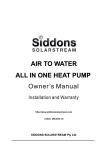
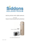
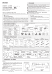
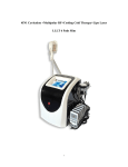
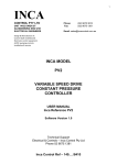
HEAT PUMP SPECIFICATIONS
For more information, go to the website:
www.siddonssolarstream.com
For installation video, go to:
www.siddonssolarstream.com/installation
To be read in conjunction with the:
Installation and User Manual
Product Brochure
Content
I. Specification........................................................................ 1
1.How it works................................................................................. 1
2.Stainless Stell Water Tank.............................................................. 1
3.Flexible and Accessible Split System.............................................. 1
II. Heat Pump........................................................................... 2
1.Technical parameter for the main unit............................................. 2
2.Current Heat Pump version........................................................... 3
3.Heat Pump check ......................................................................... 4
III. Technical Guid.................................................................... 4
1.Staring Current and Peak Current.................................................. 4
2.Electrical wiring........................................................................... 5
3.Gas Levels and Pressures............................................................. 5
4.Electionic expansion vavle............................................................ 5
IV. Use............................................. . ....................................... 6
1. Mounting and fixing method of the remote controller......................... 6
2.Use of remote controller................................................................ 6
3.Operation date setting................................................................... 10
7
V. Maintenance and repair ....................................................... 11
VI. Wiring diagram .......................................................... .. ...... 12
Notice
1.1 In order to use this product better and safer, please read this instruction carefully before install
and operate it. Please pay attention to all the notice in operation and maintenance. Save all manuals
and documentation for future reference.
1.2 Air to water pump is a special appliance. Improper installation will cause damage and danger.
It should be installed and maintained by the professionals. Please contact our authorized local
service point for installation and maintenance. Please read and follow this instruction carefully
before and during installation.
1.3 Please check whether the distribution power capacity, switch and socket are compliance with
the requirements of our unit power. Details please refer to the rating label or parameter table in
this manual.
1.4 The power should be equipped with leakage protection separately. Power cable should be
chosen in accordance with the operation requirements of the unit.
1.5 The unit must be grounded safely. Do not use the unit if grounded unsafely. Do not connect the
ground line to the neutral and or tap water pipe.
1.6 The wire must be joined in compliance with the requirements of the wiring chart. Do not alternate
and or repair the unit personally.
1.7 Do not install the unit closed to inflammable, explosive and naked light spot.
1.8 To ensure the unit operate properly, please equipped with a filter in the water input when
installation.
I
General
1. How it works
2. Stainless Steel Water Tank
Siddons Solarstream features a marine grade (316) stainless steel water tank for longer
life without the need for sacrificial anodes. Anodes are required for mild steel water tanks
and should be changed periodically in order to achieve reasonable water tank life.
Weight of the 327 litre water tank is just 73kg, much less than a glass lined steel water
tank of the same volume capacity; the 264 litre tank weighs 62kg.
The condenser coils wraps around the outside of the tank and the patented heat transfer
system delivers a broad, gentle heating over the whole surface of the tank resisting mineral
deposits on the heating surface and this maintains the efficiency of the heating surface for
life.
The refrigerant in the condenser coils on the outside of the tank walls is kept completely
away from the potable water inside the water tank; there is no chance of mishap.
3. Flexible and Accessible Split System
The split system allows design flexible options in installation and is easily accessible
for servicing. Installations may vary from the side by side configuration of heat pump and
water tank to placement of the heat pump up to 9 metres distant from the water tank including
up to 3 metres above such as installation of the heat pump on a roof with water tank on the
ground.
Both the Water Tank and the Heat Pump come pre-charged with refrigerant gas. Pre-charging
ensures the correct refrigeration charge is in the system from the factory.
1
II
Heat Pump
1. Technical parameter for the main unit
MODEL
COOLING
MAHRW015WAA
RATED CAPACITY
W
3500
RATED CURRENT
A
4.7
RATED POWER INPUT
W
1080
WW
3.15
EER
STAR RATING
HEATING
4.5
HEATING CAPACITY
W
3500
RATED CURRENT
A
4.5
RATED POWER INPUT
W
1020
WW
3.2
EER
STAR RATING
POWER SUPPLY
4
Ph/V/Hz
1/~220-240/50
A
10.2
dB(A)
53
MAX OPERATION CURRENT
NOISE LEVEL INDOOR/OUTDOOR
3
m /h
620
DEHUMIDIFICATION CAPACITY
L/h
1.5
REFRIGERANT TYPE/CHARGE
/(g)
R134a /1500(g)
W
780
D
258
H
540
Kg
10/40
Liquid
LIQUID
6.35(1/4)
GAS
Gas
9.52(3/8)
VOLUMETRIC CAPACITY
INDOOR/OUTDOOR UNIT
DIMENSION (mm)
NET WEIGHT INDOOR/OUTDOOR
CONNECTION PIPE SIZE mm(inch)
COMPRESSOR
COMPRESSOR TYPE
TYPE
Rotary
LCD REMOTE CONTROL
TEMPERATURE SETTING RANGE
Y
O
C
16-30
OPERATION MODES
4
FAN SPEEDS
3
24-HOUR
24-HOUR ON/OFF
ON/OFF TIMER
TIMER
Y
Automatic
UP/DOWN LOUVER
Manual
LEFT/RIGHT LOUVER
HI-POWER
Y
SLEEP MODE
Y
DRY MODE
Y
LED DISPLAY ON FRONT PANEL
Y
SOFT START
N
M
APPLICATION AREA*
Compressor
2
18-30
brand
Mitsubishi
model
TB36G
2
2. Current Heat Pump version
B
D
A
C
Units: mm
MAHRW
Size
A
B
C
D
015WAA
280
505
805
542
The heat comes apart easily. Firstly remove the lid, then the case can be
opened by undoing the screws. The box is insulated for sound attenuation.
3
3. Heat Pump checks
Flare Nuts
Ensure the flare nuts are tight, use two spanners and apply pressure, one spanner countering
the force of the other.
Compressor Sitting Squarely
This image shows the Heat
Pump without the casing
revealing the compressor.
Note the compressor sits in a
tray under its own weight and
can occasionally shift its
alignment during transit and/or
installation.
If there is any metallic vibrating
or rattling sound present, try
shifting the compressor with
your hands to ensure it squarely
seated in the tray.
III
Technical Guid
1. Starting Current and Peak Current
When the Heat Pump starts up for the first time, when the tank has cold water, the power
input will be approximately 700 watts / 220 volts = 3.1 amps. The current will gradually
rise over the heating cycle until it reaches the maximum power input of 1.38kw/220
volts = 6.2 amps, just before the thermostat cuts out the Heat Pump compressor. The
power input ranges between 0.8kw to 1.38kw, 1.1kw average, and will produce Heat
Output of 3.3kw at 20 deg C and 4.4kw at 30 deg C ambient temperature at lower humidity.
4
2. Electrical wiring
The unit should use dedicated power supply, power supply voltage line corresponding with rated
voltage.
The unit power cable must use copper cable, the cable diameter must ensure that the unit's
maximum starting current requirements.
The unit power supply circuit must have a grounding wire, which should connect with a reliable
external ground wire, and the external ground wire is effective.
Wiring construction must be installed by professional technicians refer to circuit diagram.
Power lines and signal line layout should be neat, rational, strong and weak lines separate and can
not interfere with each other, while not contacted with the connecting pipe and the valve body.
When power lines and control lines parallel, the wires were placed in each tube, also leave appropriate
distance between the lines.
Unit electric wire connection: take the unit power line, remote control three core lines, electric heater
power line, solar circulated water pump control power line, water tank temperature sensing line, solar
collector temperature sensor line, terminal equipments connect to unit lines, through the unit wiring
hole set into the electrical box, connect to the appropriate terminals according to wiring diagram, and
fix it by the pressure line of board in the electrical box.
Unit control panel Code MK4068, Fuse specifications: 5A/250V.
Electric wire selection
Mode
Host Power
Phase line
Zero line
Ground line
Max.line
length (m)
Signal line
MAHRW015WAA
220V/1PH/50Hz
1.5mm2
1.5mm2
1.5mm2
15
0.5mm2
Max.line
Tem. sensor
assistance line length (m)
0.5mm2
50
Note: 1. used PVC insulated copper wire for above wiring
2. for installation requires, the line is longer than the maximum line length, please contact the company.
3. Gas Levels and Pressures
The Split System comes pre-charged with the following gas levels:
For standard side by side system: 1.5 kg made up of Gas type: R22, R417a, R438a or R134a
The high pressure hot gas line will start at around 1,100 kPa at 20 deg C and lower in colder
temperatures, such as 900kPa at 10 deg C, and reach around 2,600 kPa at cut out
temperature (60 deg C water temp) irrespective of the ambient temperature.
4. Electronic expansion valve
Household air-conditioning electronic expansion valve is mainly applied in air-conditioning
system, to automatically control refrigerant flowrate, thus to make air-conditioning system
work in the best situation.
5
IV
Use
1. Mounting and fixing method of the remote controller:
The remote controller is designed and employed standard electrical box dimensions(86*86,fixed
hole distance 60mm). The electrical box and three core can be built in the wall before decoration,
which makes the interior decoration more perfect. The illustration shows as below:
Illustration 2
Illustration 1
Use a flat screwdriver to press down the two tabs
Remove the top covering leftwards to disengage
and lift open the face covering.
two top tabs.
Illustration 3
Illustration 4
Put the Digital controller into the base box and
tighten the two setting screws.
Complete the installation by pressing the Digital
Controller down firmly to reengage the tabs.
2. Use of remote controller
2.1 The user interface and function shows as below:
Keep flash (defrost status icon)
operate mode display
Running hot water mode
Keep flash
(Running manual water supply mode)
Don t flash
(Running automatic water supply mode)
Operate status,
parameter setting display
%
Buttons locking icon
Unit turn on/off button
ElEC
%
Electric heater mode icon
1
2
Timer 1(the unit turn on/off timer setting)
CLOCK TIMER
Timer 2(the automatic water supply
mode turn on/off timer setting)
Manual electric heater
turn on/off button
Timer setting button
Open the wire controller
from this button(push it)
Clock setting button
6
2.2 Initial power on and stand by status
Power on after check and confirm the unit is normal. The remote controller will be full-screen display.
The main unit will be on stand by status 10 seconds later. Distance will display the standby.
Initialization status
%
Standby status
%
1
2
ElEC
ElEC
CLOCK TIMER
CLOCK TIMER
2.3 ON/OFF control
ON/OFF
button. Press this button to power on and off. In the ON mode, the remote controller
displays the operation mode, clock, timing status, bottom of water tank temperature and ambient temperature.
Notice: When the unit power on at first time, there's no 3 minutes turning on delay. Other time, there's the 3
minutes turning on delay.
Solar collector
temperature.
Hot water
tank temperature
ElEC
CLOCK TIMER
2.4 Electric heater control
There are two mode of electric heater control, one is independent electric heater mode, another is
auxiliary electric heater mode under the hot water mode.
A: Independent electric heater mode:
under the turn off status, press the ElEC button, you can turn on the independent electric heater mode the
sign of
display on the interface like the picture 1. press the ElEC button again turn off the independent
electric heater mode like the picture 2.
ElEC
ElEC
CLOCK TIMER
picture 1
CLOCK TIMER
picture 2
B: Auxiliary electric heater mode:
under the turn on status, press the ElEC button, you can turn on the auxiliary electric heater mode, the sign
of
display on the interface like the picture 1. When the delay time which is begin when you turn on the
unit is longer than the parameter of 3 setting, the electric heater signal will output. Press the ElEC button again
turn off the auxiliary electric heater mode like the picture 2.
ElEC
ElEC
CLOCK TIMER
picture 1
CLOCK TIMER
picture 2
7
2.5 Turn on/off the water supply pump by manually.
Press the COLCK button, you can turn on the water supply pump,the sign of
display on the interface like
the picture 1 . press the COLCK button again turn off the water supply pumplike the picture 2.
ElEC
ElEC
CLOCK TIMER
picture 1
CLOCK TIMER
picture 2
2.6 Clock setting
Under power on or stand by status, press COLCK to adjust clock. The hour and minute bit flicker at
that time. Press again COLCK the hour bit flicker. Use
to adjust hour. Press COLCK again.
The minute bit flicker again. Use
to adjust minute. Press COLCK again to quit clock adjustment.
ElEC
ElEC
ElEC
CLOCK TIMER
CLOCK TIMER
CLOCK TIMER
2.7 Timer 1 ON/OFF setting
Press TIMER button for hour, minutes and timing. The ON symbol flickers. Press TIMER again, now the
hour display flickers. Press the
button to adjust the setting of the hour. Press TIMER button
again, and the minute display flickers. Press
buttons to adjust the minute setting. Press
TIMER button again and the hour and timer OFF symbol flickers. Press TIMER again and the hour display
flickers, press
button to adjust the hour setting. Press TIMER button again, and the minute
display flickers. Press
buttons to adjust the minute setting. Press TIMER button, then exit the
timer ON/OFF setting. The following example shows the heat pump set to turn on at 8:30 every
morning, and turn off at 23:30 every night.
(Timing 1 is the unit's timing ON/OFF)
1
ElEC
CLOCK TIMER
1
ElEC
CLOCK TIMER
1
ElEC
CLOCK TIMER
1
CLOCK TIMER
ElEC
1
ElEC
CLOCK TIMER
1
ElEC
CLOCK TIMER
1
ElEC
CLOCK TIMER
2.8 Setting of timing hot water supply (timing 2)
Press TIMER 5s for hour, minutes and timing. The ON symbol flickers. Press TIMER again, now the
hour display flickers. Press the
button to adjust the setting of the hour. Press TIMER button
again, and the minute display flickers. Press
buttons to adjust the minute setting. Press
TIMER button again and the hour and timer OFF symbol flickers. Press TIMER again and the hour display
flickers, press
button to adjust the hour setting. Press TIMER button again, and the minute
display flickers. Press
buttons to adjust the minute setting. Press TIMER button, then exit the
timer ON/OFF setting. The following example shows the heat pump set to turn on at 8:30 every
morning, and turn off at 23:30 every night.
(Timing 2 is the hot water supply timing ON/OFF)
8
2
CLOCK TIMER
ElEC
2
ElEC
2
CLOCK TIMER
CLOCK TIMER
ElEC
2
2
CLOCK TIMER
ElEC
CLOCK TIMER
ElEC
2
ElEC
2
CLOCK TIMER
CLOCK TIMER
ElEC
2.9 Cancellation of timing setting operation
Press
button and press
button to cancel the timing 1.
Press
5 seconds and press
button to cancel the timing 2.
2.10 Parameter setting
In the standby mode, press key
to enter the browsing interface and can see the parameters
of 0-17/A/b/c/d/E/F, then choose the parameters you want to modify, and press the key
and ELEC
at the same time to enter the interface of parameters modifying, then press the key
to modify
the corresponding parameter value, then press the
and ELEC at the same time for confirm the
modification .
Note: 1. All the parameters could not be modified under boot-up state and just can be modified
under standby mode.
In the operation, if stop operation for 10 seconds, then quit Settings.
ElEC
CLOCK TIMER
Parameter 0
Domestic hot water
tank temperature
Alternative range: 10 to 60 .
Default: 55
ElEC
CLOCK TIMER
Parameter 5
Not applicable on this
model
ElEC
CLOCK TIMER
Parameter 10
Not applicable on this
model
ElEC
CLOCK TIMER
Parameter 1
Domestic hot water ,the
compressor restart difference
temperature
Alternative range: 2 to 15 .
Default: 5
ElEC
CLOCK TIMER
Parameter 6
Defrost cycle
Alternative range: 30 to
90 min.
Default: 45 min
ElEC
CLOCK TIMER
CLOCK TIMER
ElEC
Parameter 2
Not applicable on this
model
CLOCK TIMER
ElEC
Parameter 7
Enter defrost temperature
Alternative range: -30 to 0 .
Default: -7
CLOCK TIMER
ElEC
Parameter 11
Parameter 12
The Target superheat
Electronic expansion valves
control the selection
temp.Alternative
range:-F(-15) to F(15) . 0:mannual control
1:automatic control
default setting:5
default setting:1
9
ElEC
CLOCK TIMER
Parameter 3
Not applicable on this
model
ElEC
CLOCK TIMER
ElEC
CLOCK TIMER
Parameter 4
Not applicable on this
model
ElEC
CLOCK TIMER
Parameter 8
Parameter 9
Exit defrost temperature
Exit defrost time condition
Alternative range: 2 to 30 . Alternative range: 1 to 12 min.
Default: 13
Default: 8 min
ElEC
CLOCK TIMER
Parameter 13
The electric expansion
valve operation step setting
for the manual control style
default setting :35
(measure valve=35*10)
ElEC
CLOCK TIMER
Parameter 14
The ambient setting for the
electronic expansion valves turn
back to the manual control style
Alternative range:-F(15) to 0 .
Default: -5
CLOCK TIMER
ElEC
ElEC
Parameter15
Not applicable on this
model
ElEC
CLOCK
Parameter16 The ambient
temp.setting for the unit
enter the ambient temp.
Too low protection
Alternative range:
-30 to 0 Default: - 15
(The minus sign can not
display)
ElEC
TIMER
Parameter C
System coil temperature
Alternative range: -9 to 99
Actual testing value
CLOCK TIMER
CLOCK TIMER
ElEC
Parameter17 The paramter
is set for recovering
refrigerant or adding
refrigerant
0:The unit normal running
1:The unit enter recovering or
adding refrigerant mode
Default: 0
CLOCK TIMER
Parameter d
System suction
temperature
Alternative range: -9 to 99
Actual testing value
Parameter A Hot water
tank temperature
Alternative range: -9 to 99
Actual testing value
CLOCK TIMER
ElEC
CLOCK TIMER
ElEC
CLOCK TIMER
ElEC
Parameter E
Not applicable on this
model
Parameter F
Ambient temperature
Alternative range: -9 to 99
Actual testing value
CLOCK TIMER
ElEC
Parameter b
Not applicable on this
model
CLOCK TIMER
ElEC
Parameter G
The electric expansion valve
opening Alternative r ange:
15*10
35*10
Actual testing value
Note: After recovering refrigerant or adding refrigerant,you must reset the paramter 17 to 0,or else the unit
can not heating.
3. Operation data setting
The unit's operation data can be set on the wire controller.
Please set according to the table below.
Parameter
0
1
2
range
default
Adjust
10 60
55
Adjustable
2 15
5
Adjusted by technicians
1
10 90
55
Not applicable
1
0 90
1
60 90
Content description
Domestic hot water tank temperature setting
Tank temperature difference value for the
compressor restart setting
The hot water tank temperature setting
of auxiliary electric heater mode
4
Electric heating start time delay the
time after the unit turn on
The temp. of start high-temperature
disinfection per week setting
5
High-temperature disinfection maintain time
6
Defrost cycle setting
7
Enter defrost temperature setting
-30 0
-7
Adjusted by technicians
8
Exit defrost temperature setting
2 30
13
Adjusted by technicians
9
Exit defrost max. time cycle setting
8 min
Adjusted by technicians
6
Not applicable
3
10
11
12
13
14
15
70
Not applicable
Not applicable
0 90 min
30 min
Not applicable
30 90 min
45 min
Adjusted by technicians
1 12 min
Difference temp. Value between solar
and tank for Solar pump start setting
The target superheat temperature setting
for the electric expansion valve.
The control style selection of the electronic
expansion valve
The electric expansion operation step setting
for the electric expansion manual control style
The ambient setting for the ele.c expansion
valve turn back to the manual control style
The ambient temp.setting for turn on the
EVI valve
30
1~20
-F(15) F(15)
5
Adjusted by technicians
0: manual control
1:automatic control
1
Adjusted by technicians
15*10 35*10
(35*10)
Adjusted by technicians
-F(15) F(15)
-5
Adjusted by technicians
-F(15) F(15)
5
Not applicable
10
17
The ambient temp.setting for the unit enter
the ambient temp.too low protection
The paramteris set for recovering old
refrigerant or adding new refrigerant
A
Hot water tank temperature
-9 99
Actual testing value
B
Water outlet temperature
-9 99
Actual testing value
C
System coil temperature
-9 99
Actual testing value
D
System suction temperature
-9 99
Actual testing value
E
Solar collector temperature
-9 99
Not applicable
F
Ambient temperature
-9 99
Actual testing value
G
The electric expansion valve opening
16
-30 ~0
0: normal running
1: recover or add refrigerant
15
Adjusted by technicians
0
Adjusted by technicians
15*10 35*10
Actual testing value
Note:
:is just apply to the heat pump with Aux. electric heater.
: Is just apply to the heat pump with Solar collector.
:The minus sign can t display.
In the operation, if you stop operating for 10 seconds, it will log out automatically.
V
Maintenance and repair
Malfunction Indicating Table. Determine and solve the malfuction by malfuction
code as below:
Fault
code
Malfunction and
Protection Name
Solution
Standby
Normal start
PP1
Hot water tank
temp. Sensor failure
1.Check whether the temperature thermistor of the bottom of the
water tank is connected loose or not .
2.Connect temperature thermistor of the bottom of the water tank
tight or change the temperature thermistor.
PP2
Water outlet
temp.Sensor failure
1. Check whether the temperature thermistor of the upper part of
the water tank is connected loose or not .
2. Connect temperature thermistor of the upper part of the water
tank tight or change the temperature thermistor.
PP3
System coil temp.
Sensor failure
1. Check whether the temperature thermistor of the coil is connected
loose or not .
2. Connect temperature thermistor of coil tight or change the
temperature thermistor.
PP4
System suction
temp. sensor failure
1. Check whether the exhaust temperature thermistor is connected
loose or not .
2. Connect exhaust temperature thermistor tight or change the
exhaust temperature thermistor.
PP5
Solar collector
temp. sensor failure
1. Check whether the temperature thermistor of the solar collector
is connected loose or not .
2. Connect temperature thermistor of the solar collector tight or
change the temperature thermistor.
PP6
PP7
Ambient temp. sensor
failure
1. Check whether the ambient temperature thermistor is connected
loose or not .
2. Connect ambient temperature thermistor tight or change the
ambient temperature thermistor
Water flow protection
1:Check whether lack of water in the system or cycle heating
system pipe exist air and need discharge the air.
2:check the water flow volume water pump is failure or not.
11
Check whether lack of water in the system or cycle heating system
pipe exist air and need discharge the air , or the water temperature
is too high or the refrigerant is too much or high pressure switch has
been damaged.
EE1
System high pressure
protection
EE2
System low pressure The system lack of refrigerant or the low pressure switch has been
damaged.
protection
EE3
EE4
The aux. electric heater is broken ,so the unit make overheat protection
only effective to the unit with auxiliary electrical heater
lack of water protection
Check whether the three phase power supply is normal or not,
whether the phase is lose or the phase sequence is error.
Whether the running current is large than the standard current,
check the ac.contactor connection is normal or not.
aux. electric heater
overheat protection
Power phase
sequence protection
System is running defrost program.
Unit defrosting status
EE8
Communication failure Communication wires disconnect or Connection Error.
VI Wiring diagram
Wiring diagram MK4068-0101 effective for the mode of MAHRW015WAA
Wiring diagram MK4068-0101
VA1
AC-N
OT1
CN1 CN2
Yellow
Blue
Brown
VA2
HP1
Comp
S
White
Blue
Capacitance
CN3
LP1
G/Y
R
CN19
FP1
Black Red
G/Y
Fan
×Ø
White Brown
CN4
29
28
27
26
25
24
23
22
21
20
19
18
01 02 03 04 05 06 07 08 09 10 11 12 13 14 15 16 17
SW2
Red
Capacitance
Transformer
SW1
SW3
C
OT2
T
T
T
T
T
T
T1 T2
T3
T4
T5
T6
Blue
Red
Blue
L
N
Power input
(220V/1PH/50Hz)
Legend:
: Wire controller
SW3:Unit turn on/off switch(close circuit)
Fp1: Auxiliary electric heater
: 4 way valve coil
overload
protection switch(close circuit)
VA1: 4-way valve
T1 : Hot water tank temperature
VA2: Electric expansion valve
T2 : 5K resistor
LP1: System low pressure switch
HP1: System high pressure switch T3 : System coil temperature
T4 : System suction temperature
SW1: Power phase sequence
protection switch(close circuit) T5 : 5K resistor
SW2:Water flow switch(close circuit) T6 : Ambient temperature
12
CODE:MK4068-01
MACON
AIR TO WATER HEAT PUMP