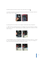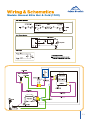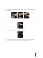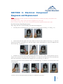
1
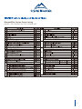
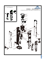
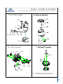
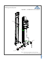
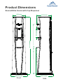
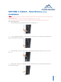
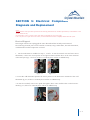
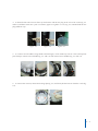
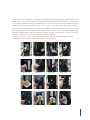
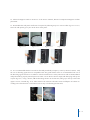
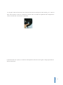
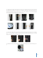
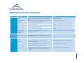
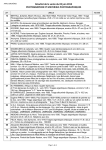
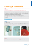
Service Manual (100-115VAC)
EVEREST ELITE
Table of Contents
SECTION1:Product Specification ................................................................................................................. 1-1
SECTION2:Parts Listing and Exploded Views......................................................................... ....................... 2-1
Everest Elite Series Parts Listing ............................................................................................................ 2-1
Exploded Views ..................................................................................................................................... 2-2
Product Dimensions ............................................................................................................................... 2-6
Description of Product Model Number ...................................................................................................... 2-8
SECTION3: Reservoir Removal.................................................................................................................... 3-1
SECTION4: Cabinet-Panel Removal and Installation...................................................................................... 4-1
Lower Front Panel Removal & Installation ................................................................................................ 4-1
Side Panel Removal ............................................................................................................................... 4-2
Side Panel Installation ........................................................................................................................... 4-4
Main Front Panel Removal & Installation ................................................................................................. 4-5
SECTION5: Electrical Component Diagnosis and Replacement....................................................................... 5-1
Electrical Diagnosis ............................................................................................................................... 5-1
Wiring and Schematics ........................................................................................................................... 5-3
Cold Thermostat Removal and Installation .............................................................................................. 5-4
Cold Thermostat Adjustment ................................................................................................................... 5-7
Hot Tank Auto Cutout / Manual Reset Replacement .................................................................................. 5-8
Hot Tank Removal and Replacement ....................................................................................................... 5-9
Hot Tank Heater Band Replacement ........................................................................................................ 5-11
Compressor Relay / Overload Protector Replacement .............................................................................. 5-12
SECTION6:Cleaning and Sanitization .......................................................................................................... 6-1
Cleaning and Sanitization ....................................................................................................................... 6-1
Parts in Contact with Water...................................................................................................................... 6-2
SECTION7:Hot Tank Venting Procedure ........................................................................................................ 7-1
SECTION8:Patented DryGuard™ Non-Spill .................................................................................................. 8-1
SECTION9: Everest Elite POU Installation..................................................................................................... 9-1
SECTION10: Product Standards .................................................................................................................. 10-1
Product Specification
EVEREST ELITE
Inspired by the award winning Everest model, Crystal Mountain
introduces the stunning Everest Elite. Innovative design features include; removable side panels, the DryGuardTM non-spill system and
raised faucet handles. It’s sleek design and upscale look is perfect for
either home or office environments. Crystal Mountain proves that
anything is possible when there is a drive to reach new heights!
Model: Everest Elite 100-115VAC
Standard Cooler Specifications and Performance Data
ITEM
POWER RATING
SPECIFICATIONS
SINGLE PHASE
100-115VAC 60Hz
STANDARD CURRENT
H&C: 4.3~4.8 A
POWER
75W
COLD
CONSUMPTION
450W
HOT
COLD
COMPRESSOR SINGLE PHASE MOTOR
R134a (30g)
REFRIGERANT
4-10°C ( 39.2-50°F)
TEMP RANGE
HOT
BAND HEATER
HEATER
74 - 92°C ( 165.2 - 197.6°F)
TEMP RANGE
SAFETY DEVICE BIMETAL (MANUAL RESET 95°C (203°F) OFF)
TEMP CONTROL BIMETAL 83°C (181.4°F)
NOISE(SOUND POWER LEVEL)
44 dB(A)
NET WEIGHT
H&C: 12.7 kg (28.0 lb)
WITH CUP
H&C: 12.4 kg (27.3 lb)
WITHOUT CUP
LOADING QUANTITY
20FT: 238UNITS
40FT: 504UNITS
1-1
Everest Elite Series Parts Listing
Model: ESE-D2 KHK1CC/ESE-D2KHK1NC
83C CERAMIC AUTO RESET,SEALED-TB
2-1
MODEL -- ESED2KHK1NC
EVEREST ELITE BOTTLED WATER COOLER (WITHOUT CUP)
1
1A
F
H
M
2
3
4
A
5
6
9
7
14
8
B
15
16
13
10
17
11
12
Note: 1. Parts may not appear exactly as shown.
2. Parts shown may not be present on all models.
2-2
K Cup Dispenser
MODEL -- ESED2KHK1CC
EVEREST ELITE BOTTLED WATER COOLER (WITH CUP)
K1
K2
1
1A
F
H
M
2
3
4
A
5
6
9
7
14
8
B
15
13
10
11
12
2-3
MODEL -- EVEREST ELITE SERIES
(HOT TANK ASSMBLY, RESERVIOR ASSEMBLY, FAUCET ASSEMBLY and DryGuardTM ASSEMBLY )
B Hot Tank Assembly
B1
B2
B3
B4
B5
B6
B7
B8
B9
M Faucet Assembly
M3
M2
M1
M5
M6
M4
Note: 1. Parts may not appear exactly as shown.
2. Parts shown may not be present on all models.
2-4
A Refrigeration System
MODEL -- EVEREST ELITE SERIES
18
A1
A2
A4
A3
Note: 1. Parts may not appear exactly as shown.
2. Parts shown may not be present on all models.
2-5
Product Dimensions
Everest Elite Cooler with Cup Dispenser
9.5 inches
12.5 inches
Front
36.3 inches
41.4 inches
5.9 inches
11.0 inches
12.9 inches
Side
Everest Elite Cooler without Cup Dispenser
9.5 inches
12.5 inches
Front
36.3 inches
41.4 inches
5.9 inches
11.0 inches
12.1 inches
Side
Description of Product Model Number
ES
Cooler Shape
E
Reservoir Type
D
2
K
H
K
1
C
Type of Lid
No. of Faucets
Body Color
Temp. Option
Insert Color
Voltage
Optional
H – Hot & Cold
K – Black
1 – 110~115V
C – Cup
N – No Cup
TM
D – DryGuard
ES – Everest Elite
K – Black
E – Plastic Reservoir
You can find your serial and model number at the back of your cooler.
2-6
SECTION 3: Reservoir Removal
Notice:
The information and/or procedures presented in the following demonstration(s) should be performed by a trained Water Cooler
Service Technician only.
Never attempt to service or repair a water cooler while it is plugged into any power supply.
Prior to any service or repair of the water cooler, ensure that the water has been completely drained from the system.
1. Turn off hot tank power switch (located near base plate at bottom) (fig. 1-1) and unplug the water
cooler.
CAUTION: WATER IN HOT TANK IS VERY HOT AND CAN CAUSE SEVERE BURNS. ALLOW SUFFICIENT TIME FOR THE HOT WATER TO COOL BEFORE DRAINING (1-2 HOURS).
Figure 1-1
2. Remove the water bottle (if applicable) (fig. 2-1). Press the cover lock and open the top cover (fig.
2-2). Drain excess water through the faucets.
Note: Water will remain in bottom half of reservoir and the hot tank; to lower the water below the faucet outlet height, tilt cooler forward slightly while depressing the cold faucet handle (fig. 2-3).
Figure 2-1
Figure 2-2
Figure 2-3
3. To drain the hot tank unscrew drain cap and remove red silicone plug at the rear of the cooler (fig.
3-1 and 3-2) and drain water into a pail or container (approx 0.5 gallon or 1.8 L) (fig. 3-3). Reinstall red
silicone plug and drain cap.
Figure 3-1
Figure 3-2
Figure 3-3
3-1
4. To remove faucet handles (using thumb and forefinger), reach inside top front of cooler and
squeeze pivot clamp to release faucet handles (fig. 4-1 and 4-2) and remove faucet handles (fig.
4-3 and 4-4).
Figure 4-1
Figure 4-2
Figure 4-3
Figure 4-4
5. To remove the reservoir, release the locking clips (fig. 5-1) and slowly lift the reservoir from the
cooler (fig. 5-2).
Figure 5-1
Figure 5-2
3-2
SECTION 4: Cabinet - Panel Removal and
Installation
Notice:
The information and/or procedures presented in the following demonstration(s) should be performed by a trained Water Cooler
Service Technician only.
Never attempt to service or repair a water cooler while it is plugged into any power supply.
Prior to any service or repair of the water cooler, ensure that the water has been completely drained from the system.
Lower Front Panel Removal & Installation
1.
Remove Drip Tray by pulling outwards from the body (fig. 1-1).
Figure 1-1
2.
Using a Philips screwdriver, remove the screw from the lower front panel (located behind
Drip tray assembly location)(fig. 2-1).
Figure 2-1
3.
Pull outwards on the lower front panel to disengage locking tabs from the front of the cooler(fig. 3-1).
Figure 3-1
4.
Install in reverse order.
4-1
SECTION 4: Cabinet - Panel Removal and
Installation
Notice:
The information and/or procedures presented in the following demonstration(s) should be performed by a trained Water Cooler
Service Technician only.
Never attempt to service or repair a water cooler while it is plugged into any power supply.
Prior to any service or repair of the water cooler, ensure that the water has been completely drained from the system.
Side Panel Removal
1.
Remove Drip Tray by pulling outwards from the body (fig. 1-1).
Figure 1-1
2.
Using a Philips screwdriver, remove the screw from the lower front panel (located behind
Drip tray assembly location)(fig. 2-1).
Figure 2-1
3.
Pull outwards on the lower front panel to disengage locking tabs from the front of the cooler
(fig. 3-1).
Figure 3-1
4.
Remove the 2 side panel installation screws from the front of the cooler (located mid way up
the front panel) (fig 4-1).
Figure 4-1
4-2
5.
Remove the 2 side panel installation screws from the back of the cooler (located mid way
up the back panel) (fig. 5-1).
Figure 5-1
6.
Open the Top Cover by pressing the cover lock(fig. 6-1), and lifting the front of the Top
Cover upwards (rotate upwards to rear of the cooler)(fig. 6-2).
Figure 6-1
Figure 6-2
Grip the top edge of the side panel and lift slightly (approximately 1/2 inch) and pull outwards from cooler to remove(fig. 7-1 to fig. 7-2).
7.
Figure 7-1
Figure 7-2
4-3
SECTION 4: Cabinet - Panel Removal and
Installation
Notice:
The information and/or procedures presented in the following demonstration(s) should be performed by a trained Water Cooler
Service Technician only.
Never attempt to service or repair a water cooler while it is plugged into any power supply.
Prior to any service or repair of the water cooler, ensure that the water has been completely drained from the system.
Side Panel Installation
1.
Identify which panel belongs on which side of the cooler (fig. 1-1 to fig. 1-2). The Locking clip
(located approximately 10 inches/250mm up from the base of the panel on the inside surface) is to
be installed towards the front of the cooler.
Figure 1-1
Figure 1-2
2.
Gripping the top edge of the side panel, insert the screw support into the slot on the Front
Panel (near Drip Tray area)(fig. 2-1 to fig. 2-2), and align the locking clip, bottom edge, upper clips,
and slide downwards to lock into place(fig. 2-3 to fig. 2-6). Install the screw into the front/back
screw supports to secure in place(fig. 2-7 to fig. 2-8).
Figure 2-1
Figure 2-2
Figure 2-5
Figure 2-6
Figure 2-3
Figure 2-7
Figure 2-4
Figure 2-8
4-4
SECTION 4: Cabinet - Panel Removal and
Installation
Notice:
The information and/or procedures presented in the following demonstration(s) should be performed by a trained Water Cooler
Service Technician only.
Never attempt to service or repair a water cooler while it is plugged into any power supply.
Prior to any service or repair of the water cooler, ensure that the water has been completely drained from the system.
Main Front Panel Removal & Installation
Note: Begin with the unit unplugged, the reservoir removed and the lower front and side
panels removed.
1.
To remove the front panel, remove the two screws on top (fig 1-1), the two screws
in the middle (fig 1-2), the two screws on the bottom (fig 1-3) and the one screw at the
back (fig 1-4).
Figure 1-1
Figure 1-2
Figure 1-3
Figure 1-4
2.
With all the screws removed, pull the front panel near the base plate forward to remove (fig 2-1 and fig. 2-2).
Figure 2-1
Figure 2-2
3.
For reassembly align the bottom of the front panel with the appropriate guides in the
base plate (fig 3-1). Then follow the above steps in reverse order.
Figure 3-1
4.
Install in reverse order.
4-5
SECTION 5: Electrical Component
Diagnosis and Replacement
Notice:
The information and/or procedures presented in the following demonstration(s) should be performed by a trained Water Cooler
Service Technician only.
Never attempt to service or repair a water cooler while it is plugged into any power supply.
Prior to any service or repair of the water cooler, ensure that the water has been completely drained from the system.
Electrical Diagnosis
Note: Begin with the unit unplugged, the water drained and the left side panel removed.
The following electrical parts can be tested for continuity using a multi-meter; hot tank thermostats,
cold thermostat and the compressor overload.
1. Set the multi-meter to audible for steps 1, 2 and 3. To test the manual reset and auto cutout
thermostats; contact one sensor probe on the upper terminal and the other on the lower terminal
of the same part (fig 1-1 and 1-2). If there is continuity there will be an audible beep.
Figure 1-1
Figure 1-2
2. To test the cold thermostat position the sensor probes on the bottom two terminals of the cold
thermostat (fig 2-1). If there is continuity there will be an audible beep.
3. To test the overload, connect one probe through the silver center and the other on the brass terminal (fig 3-1). If there is continuity there will be an audible beep.
Figure 2-1
Figure 3-1
5-1
The heater band can be tested for resistance using a multi-meter set to 200
¸
4. Touch the two terminals on heater band with the sensor probes (fig 4-1). The proper resistance is
within a range of 28 to 32.2
¸ (fig 4-2).
Figure 4-1
Figure 4-2
An amperage draw test can be done on the compressor and the heater using a clamp meter.
5. With the hot tank switched off and the unit unplugged. Locate the main lead wire coming in
from the power cord to the cold thermostat (fig 5-1) position clamp meter around this wire and
switch on (fig 5-2).
Figure 5-1
Figure 5-2
6. Plug in the dispenser. After an initial spike the reading should be within the range of 1.1-1.6A (fig
6-1). Turn on the hot tank switch; and the reading should increase to a range of 4.3-4.8A (fig 6-2).
Caution: do not leave hot tank switch on for longer than 5 seconds.
Figure 6-1
Figure 6-2
5-2
Models: Everest Elite Hot & Cold (110V)
5-3
SECTION 5: Electrical Component
Diagnosis and Replacement
Notice:
The information and/or procedures presented in the following demonstration(s) should be performed by a trained Water Cooler
Service Technician only.
Never attempt to service or repair a water cooler while it is plugged into any power supply.
Prior to any service or repair of the water cooler, ensure that the water has been completely drained from the system.
Cold Thermostat Removal and Installation
1. Turn off hot tank power switch (located near base plate at bottom)(fig. 1-1) and unplug the water
cooler .
Figure 1-1
2.
Remove Reservoir Assembly from the water dispenser (see section for Reservoir Removal Instructions).
3. Remove the Side Panels from the water dispenser (see section for Side Panel Removal Instructions).
4. Remove the mounting screw from the top of the Cold Thermostat (fig. 4-1).
5. Slide Cold Thermostat upwards to remove from the back panel (fig. 5-1).
Figure 4-1
Figure 5-1
6. Remove the wires from the bottom of the thermostat, taking care to identify where which terminals
are installed (fig. 6-1 to fig. 6-4). (Note: should show picture of proper installation and/or make reference to the wiring diagram in the service manual.)
Figure 6-1
Figure 6-2
Figure 6-3
Figure 6-4
5-4
7. Cut the small plastic tie strap (holding Cold Thermostat Sensor to Evaporator Insulation)(fig.
7-1).
Figure 7-1
8. Pull the sensor tube out from the Evaporator Insulation to remove (fig. 8-1).
Note: If required, install the Sensor tube cover onto the replacement Cold Thermostat (fig. 8-2).
Figure 8-1
Figure 8-2
9. Install the replacement Cold Thermostat into the Evaporator Insulation (insertion length approximately 5 inches/125mm)(fig. 9-1).
Note: Care should be taken while installing the sensor tube that the protective cover within the
evaporator insulation is in the proper position.
Figure 9-1
10. Install a replacement plastic tie to hold the sensor within the evaporator insulation(fig. 10-1
to fig. 10-2)
Figure 10-1
Figure 10-2
5-5
11. Reinstall the wires onto the Cold Thermostat (take care to ensure proper installation location)(Fig. 11-1 to fig. 11-3).
Figure 11-1
Figure 11-2
Figure 11-3
12. Insert bottom bracket into slot on back panel and slide downwards into position (fig. 12-1).
Figure 12-1
13. Reinstall screw on the top of the cold thermostat (fig. 13-1).
Figure 13-1
14. Reinstall Side panels and reservoir (see side panel SECTION 4, see reservoir SECTION 3).
Note: Ensure proper thermostat setting (see section for Cold Thermostat setting).
5-6
SECTION 5: Electrical Component
Diagnosis and Replacement
Notice:
The information and/or procedures presented in the following demonstration(s) should be performed by a trained Water Cooler
Service Technician only.
Never attempt to service or repair a water cooler while it is plugged into any power supply.
Prior to any service or repair of the water cooler, ensure that the water has been completely drained from the system.
Cold Thermostat Adjustment
Note: the cold thermostat can be adjusted without removal of the side panel. Setting screw is
accessible approximately 9 inches (23 cm) up from the base of the cooler on the back right side
(when viewed from the back of the cooler)
Factory Setting: 6:00
Note: to identify the 6:00 setting position, rotate the set screw clockwise until it has stopped
(screw should turn with light pressure, do not force). The top of the slotted screw is (now) in the
12:00 position. Rotate the screw counterclockwise 180 degrees to set to the 6:00 position(fig.
1-1 to fig. 1-2).
Figure 1-1
Figure 1-2
To make the water colder, rotate the screw in the clockwise direction approximately 1 hour
position. Allow the cooler to stabilize for 2-3 hours to ensure proper temperature of the cold
water. (Note: do not change the setting by more than 1 hour setting at a time to prevent freezing).
To make the water warmer, rotate the screw in the counter-clockwise direction approximately
1 hour position. Allow the cooler to stabilize for 2-3 hours to ensure the proper temperature of
the cold water.
5-7
SECTION 5: Electrical Component
Diagnosis and Replacement
Notice:
The information and/or procedures presented in the following demonstration(s) should be performed by a trained Water Cooler
Service Technician only.
Never attempt to service or repair a water cooler while it is plugged into any power supply.
Prior to any service or repair of the water cooler, ensure that the water has been completely drained from the system.
Hot Tank Auto Cutout / Manual Reset Replacement
Note: Begin with the unit unplugged, the water drained and the left side panel removed.
Tip: Use a small flathead screwdriver to pry wire connectors off.
1. Slide the silicone cover down and away from the thermostats (fig 1-1). Remove the wire connectors
from the top and bottom of the thermostat to be changed and identify (fig 1-2 and 1-3). Remove
the two screws and remove the thermostat from the bracket (fig 1-4).
Figure 1-1
Figure 1-2
Figure 1-3
Figure 1-4
2.
There is enough heat transfer paste on the tank and old thermostat to simply wipe the face
of new thermostat against the old one (fig 2-1). Place into position and evenly tighten the two
screws (torque to 3.4-6.9 lbf.in) (fig 2-2 to 2-4).
Figure 2-1
Figure 2-2
Figure 2-3
Figure 2-4
3. Reconnect the wires onto the thermostat as identified and reinstall the silicone cover (fig 3-1
to 3-3).
Figure 3-1
Figure 3-2
Figure 3-3
Note: Both thermostats can be changed in the same manner. If replacing the manual reset, ensure the reset button has been pushed prior to left panel installation.
5-8
SECTION 5: Electrical Component
Diagnosis and Replacement
Notice:
The information and/or procedures presented in the following demonstration(s) should be performed by a trained Water Cooler
Service Technician only.
Never attempt to service or repair a water cooler while it is plugged into any power supply.
Prior to any service or repair of the water cooler, ensure that the water has been completely drained from the system.
Hot Tank Removal and Replacement
Note: Begin with the unit unplugged, the water drained and the left side panel removed.
Tip: Use a small flathead screwdriver to pry wire connectors off.
1. Remove the two spring clips that secure the silicone hoses to the inlet and outlet pipes. Remove the hoses from the hot tank and identify (fig 1-1 to 1-4).
Note: Hoses may be difficult to remove. If necessary, use a flathead screwdriver to slide up between the tube and pipe to release the hoses. Be careful not to damage hoses.
Figure 1-1
Figure 1-2
Figure 1-3
Figure 1-4
2.
Remove the two screws on the hot tank drain assembly at the back of dispenser (fig. 2-1 and
2-2).
Figure 2-1
Figure 2-2
3. Slide the silicone cover down and away from the thermostats (fig 3-1). Remove and identify
the four wires from the thermostats (fig 3-2 and 3-3). With a Philips screwdriver remove the ground
wire from the thermostat bracket (fig 3-4).
Figure 3-1
Figure 3-2
Figure 3-3
Figure 3-4
5-9
4. Pull the two wires that are connected to the heater band out through the silicone cover (fig
4-1).
Figure 4-1
5. Remove the single screw that secures the hot tank in place (fig 5-1). Carefully slide the hot tank
out from the bracket (fig 5-2).
Figure 5-1
Figure 5--2
6.Reinstall the new hot tank, following the steps in reverse order. Reconnect all wires as identified,
if necessary refer to the wiring diagram. Reconnect the two hoses as identified and spring clips.
5 - 10
SECTION 5: Electrical Component
Diagnosis and Replacement
Notice:
The information and/or procedures presented in the following demonstration(s) should be performed by a trained Water Cooler
Service Technician only.
Never attempt to service or repair a water cooler while it is plugged into any power supply.
Prior to any service or repair of the water cooler, ensure that the water has been completely drained from the system.
Hot Tank Heater Band Replacement
Note: Begin with the hot tank assembly removed from the dispenser.
1. Carefully remove and identify the wire connectors from the heater band (fig. 1-1 and fig. 1-2).
Figure 1-1
Figure 1-2
2.
Remove the bolt that tightens the heater band onto the hot tank (10mm wrench) (fig. 2-1). Turn the
heater band until the opening lines up with the stainless J tube and pull down to remove completely from
the hot tank (fig. 2-2 and 2-3).
Figure 2-1
Figure 2-2
Figure 2-3
3. Install the new heater band by following the steps above in reverse order, ensuring that the wire terminals are located near the top of the heater band (fig. 3-1). Align the opening in the heater band directly
below the thermostats, reinstall the bolt and tighten to 34.71 lbf.in (fig. 3-2 and 3-3).
4. Reconnect the wires to the terminals as they were identified (fig. 4-1 and 4-2). If necessary refer to the
wiring diagram.
Figure 3-1
Figure 3-2
Figure 3-3
Figure 4-1
Figure 4-2
5. Refer to the hot tank replacement procedure for installation instructions.
5 - 11
SECTION 5: Electrical Component
Diagnosis and Replacement
Notice:
The information and/or procedures presented in the following demonstration(s) should be performed by a trained Water Cooler
Service Technician only.
Never attempt to service or repair a water cooler while it is plugged into any power supply.
Prior to any service or repair of the water cooler, ensure that the water has been completely drained from the system.
Compressor Relay / Overload Protector Replacement
Note: Begin with the unit unplugged, the water drained and the left side panel removed.
Tip: Use a small flathead screwdriver to pry wire connectors and relay from compressor.
1. Remove the relay/overload cover by prying the metal clip to unhook it from the compressor on
both sides (fig 1-1 and 1-2).
Figure 1-1
Figure 1-2
2.
Carefully remove and identify the wire connectors from the relay (white wires) and/or overload
(black wire) (fig 2-1 and 2-2). Remove relay and overload from compressor (fig 2-3 and 2-4).
Figure 2-1
Figure 2-2
Figure 2-3
Figure 2-4
3. Install the new overload onto the top pin of the compressor (fig 3-1) and push the new relay onto
the two bottom pins below the overload (fig 3-2). Reconnect the white wires onto the relay (fig 3-3)
and the black wire onto the overload (fig 3-4).
4. Reinstall the cover and secure with the metal clip (fig 4-1). Note: use caution not to damage wires.
Figure 3-1
Figure 3-2
Figure 3-3
Figure 3-4
Figure 4-1
5 - 12
SECTION 6: Cleaning and Sanitization
Notice:
The information and/or procedures presented in the following demonstration(s) should be performed by a trained Water Cooler
Service Technician only.
Never attempt to service or repair a water cooler while it is plugged into any power supply.
Prior to any service or repair of the water cooler, ensure that the water has been completely drained from the system.
Scheduled cleaning and sanitizing is recommended to ensure the integrity of the drinking water. Scheduling will vary depending on the conditions and environment in which the cooler is in use. Follow the steps
outlined below for the recommended procedures for sanitizing the water cooler.
CAUTION: DO NOT IMMERSE THE UNIT IN WATER OR CLEAN USING PRESSURE WASHER.
1. Use latex or nitrile gloves or wash hands before and after handling water contact parts.
2. Turn off hot tank power switch (located near base plate at bottom) (fig. 2-1) and unplug the water
cooler.
CAUTION: WATER IN HOT TANK IS VERY HOT AND CAN CAUSE SEVERE BURNS. ALLOW SUFFICIENT TIME FOR THE HOT WATER TO COOL BEFORE DRAINING (1-2 HOURS).
Figure 2-1
3. Remove the water bottle (if applicable). Remove drip tray assembly and set aside for cleaning (fig.
3-1). Press the cover lock and open the top cover (fig. 3-2), remove DryGuardTM by lifting from one edge
only with slow steady pressure (fig. 3-3) and set aside for cleaning. Drain excess water through the faucets.
Note: Water will remain in bottom half of reservoir and the hot tank; to lower the water below the faucet
outlet height, tilt cooler forward slightly while depressing the cold faucet handle (fig. 3-4).
Figure 3-1
Figure 3-2
Figure 3-3
Figure 3-4
6-1
4. To drain the hot tank unscrew drain cap and remove red silicone plug at the rear of the cooler (fig. 4-1
and 4-2) and drain water into a pail or container (approx 0.5 gallon or 1.8 L) (fig. 4-3). Reinstall red silicone
plug and drain cap.
Figure 4-1
Figure 4-2
Figure 4-3
5. To remove faucet handles (using thumb and forefinger), reach inside top front of cooler and squeeze
pivot clamp to release faucet handles (fig. 5-1 and 5-2) and remove faucet handles (fig. 5-3 and 5-4).
Figure 5-1
Figure 5-2
Figure 5-3
Figure 5-4
6. To remove the reservoir, release the locking clips (fig. 6-1) and slowly lift the reservoir from the cooler (fig.
6-2).
Figure 6-1
Figure 6-2
6-2
7. Remove baffle assembly from the reservoir (fig. 7-1). Empty remaining water from reservoir
(fig. 7-2).
Figure 7-1
Figure 7-2
8. Remove faucet assembly by pulling away from reservoir (fig.8-1).
Figure 8-1
9. To remove the cold and hot faucet assemblies from the faucet outlet it is not required to remove the
2 screws. Holding one faucet in each hand, bend the faucets in the middle upwards until they become
separated (fig. 9-1). Remove the faucets one at a time by sliding away from the corresponding screw (fig.
9-2 to 9-3).
Figure 9-1
Figure 9-2
Figure 9-3
6-3
10. Remove the two silicon faucet seals from the inlet end (fig. 10-1) and unscrew the faucet cap by rotating it counterclockwise to separate the top and bottom halves of the faucet assembly (fig. 10-2 and 10-3).
Figure 10-1
Figure 10-2
Figure 10-3
11. Using only FDA approved sanitizing products, thoroughly clean all water contact parts and drip tray.
The use of these products must be in accordance with the manufacturer’s safety instructions and recommendations and performed by properly trained personnel.
12. Remove front bottom panel by removing screw and set aside (fig.12-1 and 12-2). Remove both side
panels by removing the 4 screws (fig.12-3 and 12-4) and open top cover to lift panels off of locator pins
(fig.12-5 to 12-7). Clean all 3 panels using only a mild non-abrasive cleaning agent. The use of bleach or
abrasive cleaners is not recommended.
Figure 12-1
Figure 12-2
Figure 12-5
Figure 12-3
Figure 12-6
Figure 12-4
Figure 12-7
6-4
13. Using the brush attachment, vacuum the condenser and all accessible areas to remove dirt, lint and
debris (fig. 13-1 to 13-9) (the use of the crevasse tool attachment may also be used). Use a scrub brush
to remove dirt and debris from the condenser (fig. 13-5). Use an air hose to remove debris from inaccessible areas (do not exceed 100 PSI) (fig. 13-6 to 13-8). Use a damp cloth to wipe down condenser
(fig. 13-9). For excessively dirty coolers, the back condenser may be moved back 4”- 6” by removing
the screws that secure the condenser to the back panel (fig. 13-10 to 13-13). Use a damp cloth to wipe
down the complete back panel, the Styrofoam insulation and the compressor (fig. 13-14 to 13-16). Replace screws in condenser when cleaning of back panel is complete.
CAUTION: DO NOT CLEAN USING PRESSURE WASHER OR ANY DIRECT WATER CONTACT.
CAUTION: DO NOT MOVE CONDENSER MORE THAN 6 INCHES.
Figure 13-1
Figure 13-2
Figure 13-3
Figure 13-4
Figure 13-5
Figure 13-6
Figure 13-7
Figure 13-8
Figure 13-9
Figure 13-10
Figure 13-11
Figure 13-12
Figure 13-13
Figure 13-14
Figure 13-15
Figure 13-16
6-5
14. Electrical Diagnosis. Refer to Section 5 of the Service Manual; Electrical Component Diagnosis and Replacement.
15. Reassemble the side panels and lower front panel by following step 12 in reverse order (fig.15-1 to 15-7).
Note: the side panels go on prior to the lower front panel.
Figure15-1
Figure 15-2
Figure15-5
Figure 15-3
Figure 15-6
Figure 15-4
Figure 15-7
16. It is recommended that the hot tank be descaled periodically (frequency varies by mineral content). Only
the use of descaling agents that are compatible with 304 grade stainless steel are recommended. The use of
the descaling agents must be in accordance with the manufacturer’s safety instructions and recommendations
and performed by properly trained personnel. Note: ensure the hot tank is empty and drain plug and cap are
in place (fig 16-1). Using a funnel, add the descaling solution to the hot tank, filling up to the top of the inlet
(approx 38.7oz /1100ml) (fig. 16-2). Allow time for the solution to descale. Drain and dispose of solution according to the manufacturer’s instructions (refer to step 4 for draining the hot tank).
Figure 16-1
Figure 16-2
6-6
17. The upper reservoir support can be wiped clean (Fig 17-1). Using a bottle brush and the sanitizing
solution from step 11, clean the hot tank inlet and outlet openings (Fig 17-2 to 17-3). Prior to rinsing the
hot tank, position pail or container under drain assembly and using a sanitized funnel; thoroughly rinse
the hot tank (fig. 17- 4).
Figure 17-1
Figure 17-2
Figure 17-3
Figure 17-4
Note: Prior to reassembly, thoroughly rinse and dry all water contact parts that have been removed.
18. Reassemble in reverse order. Ensure all seals/gaskets are reinstalled properly, and install red silicone
plug and drain cap (fig.18-1). The use of air-pressure test equipment is recommended to verify the reassembly process has been done correctly (recommended 1.0~1.2 PSI) (fig. 18-2).
Note: when reinstalling the DryGuardTM replace air filter cloth (Part # MIS-C100043) (fig. 18-3) and ensure proper installation of the DryGuardTM into the reservoir (the word front to the front of the cooler) (fig.
18-4).
Figure 18-1
Figure 18-2
Figure 18-3
Figure 18-4
19. Place a new bottle on the cooler. Important: Prior to plugging in cooler, vent the hot tank by holding
the hot faucet open until water flows.
20. Draw one cup of water from each faucet and discard.
6-7
21. Plug the cooler back into the power outlet and turn the hot tank power switch ON (fig. 21-1). Do not
draw water from the cooler for 30 minutes to let the water cool and heat. Optimum water temperatures
will be reached after several hours of operation.
Figure 21-1
Crystal Mountain has a policy of continuous development and reserves the right to change specifications
without notification.
6-8
Parts in Contact with Water
for Everest Elite Water Cooler
NO.
PART NO.
PART DESCRIPTION
MATERIAL TYPE FORMULATION MATERIAL SUPPLIER
& PIGMENT
IN NUMBER
DOCUMENT CONTROL CODE
1
PLC-C000088
CRYSTAL CONE PIN
PC
2
PLC-C100047
PP
BAYER MATERIALSCIENCE
FORMOSA PLASTICS
3
PLC-C100213
DryGuard TM FILTER
CAP
DryGuardTM
MAKROLON
2858
PP 3015
PP
TPR
PP 3015
TF6ATL
21 CFR 177.1580 “POLYCARBONATE RESINS”.
NSF 51
SGS:CY/2009/A0913
UL:E216959
HP120867
4
PLC-C140033
PP
PP ST611M
5
PLC-C140006
DryGuard TM FLOAT
RING
FAUCET BODY
PP
PP 3015
6
PLC-C140009
RESERVOIR
PP
PP K8009
7
PLC-C140070
BAFFLE
PP
PP 3015
FORMOSA PLASTICS
CORPORATION
SGS:CY/2009/A0913
UL:E216959
8
PLC-C140011
FAUCET OUTLET
PP
PP 3015
9
PLC-C140028
SIPHON TUBE
HDPE
HDPE 8001BL
SGS:CY/2009/A0913
UL:E216959
SGS:CY/2010/70671
10
SIL-C000010
NBR
NBR3445
11
SIL-C120006
O-RING, CRYSTAL
PIN
SEAL, MANIFOLD
INLET/OUTLET
SILICON
ZH9250
12
SIL-C120010
SILICON TUBE 14MM ID X 300MM
SILICON
ZH44
13
SIL-C140001
FAUCET PLUNGER
SILICON
ZH9250
FORMOSA PLASTICS
CORPORATION
FORMOSA PLASTICS
CORPORATION
WING CHEONG TAI
TECHNICAL CO. CHINA
DONG GUAN HONG DA
NEW MATERIAL CO.,
LTD
DONG GUAN HONG DA
NEW MATERIAL CO.,
LTD
DONG GUAN HONG DA
NEW MATERIAL CO.,
LTD
CORPORATION
FORMOSA PLASTICS
CORPORATION
KRAIBURG TPE CORP.
LCY CHEMICAL INDUSTRY CORP.
FORMOSA PLASTICS
CORPORATION
FORMOSA CHEMICAL &
FIBRE CORPORATION
21 CFR 177 1520(A)
SGS:CY/2009/A0913
UL:E216959
“SGS: CY/2010/41687“
UL:E162823”
21 CFR FDA 177 2600
GZ0909086311/CHEM
SGS:GZ0909086307A/CHEM
FDA REFERENCE:FDA 21
CFR 177.2600
GZ0909086311/CHEM
6-9
SECTION7: Hot Tank Venting Procedure – Everest Elite Water Cooler
Notice:
The information and/or procedures presented in the following demonstration(s) should be performed by a trained Water Cooler
Service Technician only.
Never attempt to service or repair a water cooler while it is plugged into any power supply.
Prior to any service or repair of the water cooler, ensure that the water has been completely drained from the system.
The new specially designed Everest Elite hot tank has a self-venting feature. For proper installation please follow the steps outlined below:
1. Position cooler appropriately and place the water bottle on the cooler (fig. 1-1).
2. Plug the cooler into an appropriate power supply/outlet (fig. 2-1).
Figure 1-1
Figure 2-1
3. Hold the hot faucet open for approximately 1 minute and then turn on the hot tank switch (fig. 3-1 and
3-2).
Figure 3-1
Figure 3-2
4. The hot tank will not be completely full; there is an air-vent inside the cold reservoir that allows the hot
tank to finish filling - at this point the RSR’s set up of the unit is complete (fig. 4-1).
Figure 4-1
Note: Please allow 20 minutes before drawing water to allow the hot water to reach temperature. Should you
attempt to draw water from the hot faucet within the 20 minutes, you may encounter an air-lock. This air-lock
goes away after the hot water reaches temperature so it isn’t necessary for the RSR to remain on site.
If you have any further questions please contact us by email at [email protected] or toll free at 800878-6422.
7-1
SECTION 8: Patented DryGuardTM Non-Spill
Crystal Mountain’s
DryGuardTM is designed
to protect against leaks
caused by cracked or
faulty bottles. It is the
industry’s most effective
and reliable.
8-1
SECTION 9: Everest Elite POU Installation
Notice:
The information and/or procedures presented in the following demonstration(s) should be performed by a trained Water Cooler
Service Technician only.
Never attempt to service or repair a water cooler while it is plugged into any power supply.
Prior to any service or repair of the water cooler, ensure that the water has been completely drained from the system.
Dispenser Preparation
1. Remove the water bottle (if applicable) (Fig. 1-1) Press the cover lock and open the top cover (Fig.
1-2)
Figure 1-1
Figure 1-2
2. Press the rib at the top of the back panel (Fig. 2-1), slide out the stainless steel axis (Fig. 2-2) and
remove the top cover (Fig. 2-3).
Figure 2-1
Figure 2-2
Figure 2-3
3. Remove DryGuardTM by lifting from one edge only with slow steady pressures (Fig. 3-1 to Fig.
3-2).
Figure 3-1
Figure 3-2
9- 1
4. Remove Drip Tray by pulling outwards from the body (Fig. 4-1). Using a Philips screwdriver, remove the screw from the lower front panel (located behind Drip tray assembly location)(Fig. 4-2)
Pull outwards on the lower front panel to disengage locking tabs from the front of the cooler (Fig.
4-3)
Figure 4-1
Figure 4-2
Figure 4-3
5. Remove the 2 side panel installation screws from the right hand side of the cooler (located midway up the front panel on the front and back) (Fig. 5-1 to Fig. 5-3)
Figure 5-1
Figure 5-2
Figure 5-3
POU Installation
6. Remove the cardboard spacer located between the 2 float arms (Fig. 6-1) Install the primary float
(Fig. 6-2)
Figure 6-1
Figure 6-2
9- 2
7. Insert the 1/4 inch blue tubing (Connected to POU Assembly) through the hole provided on the
Upper Support (Fig. 7-1) and then through the hole provided near the bottom of the back panel (Fig.
7-2)
Figure 7-1
Figure 7-2
8. Install the POU assembly on the reservoir, ensuring that it is correctly fitted (POU assembly
marked with the word FRONT) (Fig. 8-1 to Fig. 8-2)
Figure 8-1
Figure 8-2
9. Ensure the indicator is correctly set. The bar on the indicator will be to the front (Fig. 9-1) Working Position (Fig. 9-2) Locked (Reset) position (Fig. 9-3).
Figure 9-1
Figure 9-2
Figure 9-3
9- 3
10. Gripping the top edge of the side panel, insert the screw support into the slot on the Front Panel
(near Drip Tray area) (Fig. 10-1 to Fig. 10-2), and align the locking clip, bottom edge, upper clips,
and slide downwards to lock into place (Fig 10-3 to Fig 10-6). Install the screw into the front/back
screw supports to secure in place (Fig. 10-7 to Fig. 10-8)
Figure 10-1
Figure 10-2
Figure 10-3
Figure 10-4
Figure 10-5
Figure 10-6
Figure 10-7
Figure 10-8
11. Insert bottom edge of lower front panel to the base plate and push locking tabs into front panel.
(Fig. 11-1) Using a Philips screwdriver, install the screw to the lower front panel (Fig. 11-2) Install
Drip Tray by pushing inwards to the body (Fig. 11-3).
Figure 11-1
Figure 11-2
Figure 11-3
12. Install the POU top cover and replace the stainless steel axis (Fig. 12-1). Close the POU top cover.
Figure 12-1
9- 4
SECTION 10: Product Standards
Item
Performance
Noise
Standard No.
Title
Content
ARI 1010
Performance standard
ANSI/ASHRAE
18-2000
Self-Contained,Mechanically-Refrigerated Drinking Water
Coolers
Methods of Testing for Rating Drinking-Water Coolers with
Self-contained Mechanical Refrigeration
JIS C 9618-1992
Drinking -Water Coolers
Performance and method for coolers (in Japanese
method)
GB/T 22090-2008
Cold & Hot Drinking Water Coolers
Performance and method for coolers (in Chinese
method)
GKE-III-TS-RTD016(our company
standard)
Performance & Testing Standard for Everest Series
Drinking Water Coolers
Performance and method for coolers (in GKE method)
Household and similar electrical appliances-Test code for
the determination of airborne acoustical noise--General
requirements
Noise testing method for coolers (sound power level)
IEC 60704-1
Standard for Drinking-Water Coolers
Safety standard (American) -for coolers
Safety of household and similar electrical appliances--General requirements
Safety standard (Europe) - for electrical appliance
ICE60335-1
Safety of household and similar electrical appliances--Particular requirements for storage water heaters.
Particular safety standard - Hot tank
ICE60335-2-21
Safety of household and similar electrical appliances--Particular requirements for refrigerating appliances and
Ice-makers.
Particular safety standard-refrigeration system
ICE60335-2-24
UL 399
Safety
Methods of testing for coolers
10 - 1
Crystal Mountain Products Limited
North American Sales Office
11925 -145 th Street
Edmonton, Alberta
Canada T5L 2H4
Tel: 1 800 878 6422
Tel: 1 780 454 4545
Fax: 1 780 454 9816
E-mail: [email protected]
European Sales Office
Fence House, Fence Avenue
Macclesfield, Cheshire
United Kingdom SK10 1LT
Tel: +44(0) 1625 439 111
Fax: +44 (0) 1625 502 527
E-mail: [email protected]
Crystal Mountain Products Inc.
US Office / Warehouse
915 Taylor Rd, Unit 3
Gahanna OH 43230
Tel: (614) 454 1618
Fax: (614) 409 9782
E-mail: [email protected]
Crystal Mountain International Limited
Hong Kong Sales Office
Room 610, Winfield Commercial Building
6-8a Prat Avenue, Tsimshatsui
Kowloon, Hong Kong
Tel: (852) 2368 1989
Fax: (852) 3017 6727
E-mail: [email protected]
Website: www.crystalcoolers.com
Crystal Mountain has a policy of continuous development and reserves the right to change specifications without notification.
ESESM REV0315