1
USBwiz User Manual
Rev.2.27
Date: April 20, 2009
User Manual
Document Information
Information
Description
Abstract
This document covers complete information about
USBwiz, specifications, tutorials, and references.
G H I
E l e c t r o n i c s
GHI Electronics,LLC
USBwiz User Manual
Table of Contents
Table of Contents
1.Introduction....................................................................................................................................................3
1.1.Example applications.............................................................................................................................3
1.2.Key features...........................................................................................................................................3
1.3.USBwiz Circuit Boards...........................................................................................................................4
2.USBwiz Architecture......................................................................................................................................6
2.1.Block Diagram.......................................................................................................................................6
2.2.LPC2134 Microcontroller.......................................................................................................................7
2.3.Commander...........................................................................................................................................8
2.4.FAT File System.....................................................................................................................................8
2.5.USB Hosting..........................................................................................................................................8
2.6.Supported USB Client Classes..............................................................................................................9
3.Pin-Out and Description...............................................................................................................................10
4.Communication Interface selection..............................................................................................................13
4.1.Selecting an Interface..........................................................................................................................13
4.2.UART Interface....................................................................................................................................13
4.3.SPI Interface Mode..............................................................................................................................13
4.4.I2C Interface Mode..............................................................................................................................15
5.Getting Started with USBwiz........................................................................................................................16
6.1. USBwiz Functions....................................................................................................................................20
6.1.Commander.........................................................................................................................................20
6.2.FAT Storage Media..............................................................................................................................20
6.3.USB Mass Storage..............................................................................................................................21
6.4. USB Human Interface Device.............................................................................................................21
6.5.USB Printers........................................................................................................................................28
6.6.USB Serial Devices.............................................................................................................................29
6.7.Raw USB Access.................................................................................................................................29
7.USBwiz Command Set................................................................................................................................33
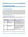
8.USBwiz Boot Loader....................................................................................................................................58
8.1.General Description.............................................................................................................................58
8.2.Boot Loader Commands......................................................................................................................58
8.3.Firmware Update.................................................................................................................................59
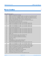
Error Codes....................................................................................................................................................60
USBwiz Events...............................................................................................................................................63
DISCLAIMER..................................................................................................................................................64
Rev.2.27
Page 2 of 64
www.ghielectronics.com
GHI Electronics,LLC
USBwiz User Manual
Introduction
1. Introduction
USBwiz is an optimized solution for easy interfacing almost any embedded system to USB
hosting with a vast variety of USB drivers such as Printer Driver, HID Driver (mice,
keyboards and joysticks), CDC Driver (modems, cellphone), USB-to-Serial device Drivers (
FTDI, Silabs, Prolific) and Mass Storage Driver (Thumb Drives, memory readers, ..etc)
accompanied with very reliable and fast FAT file system that allows the system to access
storage medias and open or create files and folders.
USBwiz connects to a USB host controller (ISP1160) on one side and to your
microprocessor on the other side (PIC, AVR…etc.). Using simple commands over I2C, SPI
or UART (serial) you can talk to almost any USB device on the market.
1.1. Example applications
●
●
●
●
●
●
●
●
Digital camera
Data Logger
Picture viewer
USB thumb-drive MP3 player
Automated machine
Keyboard/mouse/joystick interface
RS232 to “USB-printer” server
Automated SMS Sending
1.2. Key features
●
●
●
●
●
●
●
●
●
●
●
●
●
●
●
FAT32, FAT16 and FAT12 support
Simultaneous access to 3 FAT devices
Multi Media Card (MMC) and Secure Digital (SD) memory cards
USB host stack and raw access to USB devices
HID support
Printer support
Mass storage support
Utilizes ISP1160
Easily used with any microcontroller including PIC, AVR, Zilog…etc.
Runs with simple robust protocol over UART, I2C or SPI.
UART runs as high as 921.6 K-baud, I2C up to 400kbps, and SPI clock is up to 7
MHz.
Field upgradeable firmware from a file on the connected media!
Built in RTC (Real Time Clock)
Very few external components are needed
Small LQFP 64 package
Rev.2.27
Page 3 of 64
www.ghielectronics.com
GHI Electronics,LLC
USBwiz User Manual
Introduction
●
●
●
●
●
40 to 50 mA, power consumption
Single supply 3.3V
5V tolerant I/O pins
-40˚C to +85˚C temperature operating range
Lead free
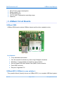
1.3. USBwiz Circuit Boards
USBwiz-OEM:
USBwiz-OEM board contains USBwiz chipset and the other needed circuitry.
key features:
●
Fully assembled and tested
●
Can be mounted to almost any case using 90 degrees brackets
●
Standard .1" spaced holes for header for user interface
●
Secure Digital (SD)/ Multi Media Card (MMC) Card connector
●
Dual USB connector
●
Requires "regulated" 5V
USBwiz-BOX ( USBwiz in case solution ):
This powerful board (formally known as USBwiz-DEV) is a complete USB host system.
Rev.2.27
Page 4 of 64
www.ghielectronics.com
GHI Electronics,LLC
USBwiz User Manual
Introduction
Thanks to USBwiz chip, through RS232, UART, SPI or I2C interfaces you can access
many USB devices, including USB memory drives. Also, you can read/write files from
the any formatted SD or MMC card. The board comes with the D-SUB25 connector to
access all USBwiz's functionality. Look at the schematics for more details.
key features:
●
Based on USBwiz chip
●
Completely built and tested
●
Plugs directly to any RS232 port, DTE (computer) or DCE (device)
●
D-SUB25 with connections to all features, including UART, SPI and I2C.
●
Designed to go directly in a plastic case
Rev.2.27
Page 5 of 64
www.ghielectronics.com
GHI Electronics,LLC
USBwiz User Manual
USBwiz Architecture
2. USBwiz Architecture
USBwiz is a single chip that performs all work needed for USB hosting and FAT file
system. USBwiz connects to a USB host (ISP1160) on one side and to your product on the
other side (PIC, AVR…etc.) Using simple commands over I2C, SPI or UART (serial), you
can use almost any USB device on the market. If the device falls under a supported USB
class, no USB knowledge is necessary, USBwiz does the work. This includes many of-theshelf devices such as mouse, keyboard, joystick, USB memory, printer, modem (cell
phones), and many more!
Also, USBwiz includes FAT file system. Microsoft FAT file system allows your product to
create files on USB/SD storage media devices.
Rev.2.27
Page 6 of 64
www.ghielectronics.com
GHI Electronics,LLC
USBwiz User Manual
USBwiz Architecture
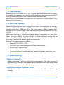
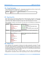
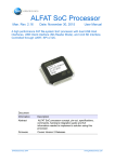
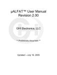
2.1. Block Diagram
SD/MMC
SPI Dirver
FAT File System
Controller
Master System
AVR, PIC ...etc
UART,SPI
or I2C
Human-friendly Commander
SPI
SD/MMC
USB-to-Serial Driver
USB
port0
ISP1160
CDC Driver
Data bus
USB Host Controller
Printer Driver
USB Host driver
HID Driver
USB Driver
Mass Storage Driver
Mass Storage
Device
HID...Keyboard,
mouse,,joystick..etc
USB to Serial
FTDI,Silabs,Prolific.
USB
port1
USB Printer Device
AT command
modem, cellphone
USBwiz LPC2134
2.2. LPC2134 Microcontroller
The LPC2134 microcontroller is based on a 32/16 bit ARM7TDMI-S CPU with real-time
emulation and embedded trace support, that combines the microcontroller with embedded
high speed 256KB flash memory. A 128-bit wide memory interface and a unique
accelerator architecture that enables 32-bit code execution at the maximum clock rate.
Rev.2.27
Page 7 of 64
www.ghielectronics.com
GHI Electronics,LLC
USBwiz User Manual
USBwiz Architecture
2.3. Commander
USBwiz uses LPC2134 UART, SPI or I2C to let the user communicate with boot loader,
Commander. All commands are entered in ASCII characters. We chose to use ASCII to
simplify troubleshooting and to allow humans to enter commands easily.
Main function of Commander is to provide user with simple tool to control USBwiz to get
the full use of its functions.
2.4. FAT File System
USBwiz can connect to two kinds of storage media types. The media types are SD/MMC
cards and USB Mass Storage devices (SCSI command subclass, bulk only protocol) which
includes thumb flash, USB hard drives and card readers. USBwiz supports three
simultaneous FAT devices. Keep in mind that all devices must be formatted FAT12, FAT16
or FAT32.
USBwiz can mount up to 3 File System Medias that are independent from each other,
which means that all opened files and operations in one file system has no effect on the
others. This gives USBwiz very great capability of flexible switching between the file
system Medias and providing other valuable functions like reading from file in one Media
and writing in another file in another media at the same time.
Some FAT File System features in USBwiz:
●
Supports FAT12,FAT16, FAT32
●
Can mount up to three independent File System independently
●
accesses up to 4 opened files
●
access unlimited subdirectory (folders) trees
●
File access functions includes read, write, append, find, delete, make folder...etc.
2.5. USB Hosting
USB Host Controller
USBwiz connects to a USB host (ISP1160) through data bus. This Host Controller is
manufactured by Phillips to fit embedded system applications with USB full speed and
USB version 2.0 compatibility. It provides two USB host ports with internal root hub.
USB Driver and Host Controller Driver
USBwiz has a reliable USB driver that can fully control the traffic on ISP1160 Host
Controller.
Rev.2.27
Page 8 of 64
www.ghielectronics.com
GHI Electronics,LLC
USBwiz User Manual
USBwiz Architecture
2.6. Supported USB Client Classes
The USB organization defines many classes for different USB devices. This means all
USB devices of a certain type; keyboards for example, should run the same way. This is
the reason why you do not need to install drivers when connecting a keyboard to your PC.
Your operating system includes the “USB class drivers”. USBwiz comes with many USB
class drivers. If a class is not supported by USBwiz, you can still use it by accessing the
raw USB commands.
USB supported Devices:
●
Human Interface Devices (HID) such as mouse, keyboard and joystick.
●
Printers.
●
Mass Storage (Thumb drives and external USB hard drives).
●
Communication Device Class (Modems and cell phones) that contain Abstract
Control Model Subclass Interface like Nokia Cell phones.
●
USB to serial drivers such as FTDI, Silabs and Prolific.
Rev.2.27
Page 9 of 64
www.ghielectronics.com
GHI Electronics,LLC
USBwiz User Manual
Pin-Out and Description
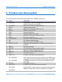
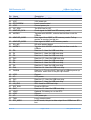
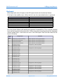
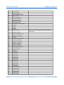
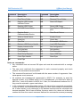
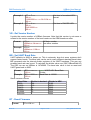
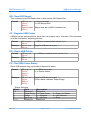
3. Pin-Out and Description
The following table includes brief description about USBwiz chip pinouts:
Pin Name
Description
1
UH_RD#
2
3
4
5
6
7
8
9
10
11
12
13
UH_WR#
RTXC1
D11
RTXC2
VSS
V3A
D10
MISC
UH_RESET#
A0
D9
ACTIVITY_LED
14
15
16
17
18
19
MISC1
SD_DET
D8
SD_CS#
VSS
UART_TX
Read strobe. Used for USB host chip (must have a pull-up
resistor on this pin or UH_CS#)
Write strobe. Used for USB host chip
32KHz crystal for RTC
Data line 11. Used for USB host chip
32KHz crystal for RTC
Connect to ground
Analog supply source 3.3V
Data line 10. Used for USB host chip.
For future expansion
Reset pin. Used for USB host chip.
A0. Used for USB host chip
Data line 9. Used for USB host chip
Goes high when executing a command and low when
finished.
Currently not used
SD card detect. Edge sensitive signal.
Data line 8. Used for USB host chip.
Chip select line for MMC or SD card
Connect to ground
In UART mode this is the transmit pin
SPI_DATARDY
I2C_DATARDY
20
21
TRST#
UART_RX
SPI_BUSY
In SPI and I2C modes, this flag indicates that USBwiz has
data ready in SPI or I2C buffer and the master must read
it. USBwiz will ignore any incoming command when this
pin is high.
Leave Unconnected
In UART mode this is the data receive pin
In SPI and I2C modes, this pin is a flag that indicates that
USBwiz is busy and it will not accept any commands
I2C_BUSY
Rev.2.27
Page 10 of 64
www.ghielectronics.com
GHI Electronics,LLC
USBwiz User Manual
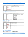
Pin-Out and Description
Pin
22
23
24
25
26
27
28
Name
I2C_SCL
VCC
RTCK/DBG#
VSS
I2C_SDA
MMC/SD_SCK
MODE0
29
MMC/SD_MISO
30
31
32
MMC/SD_MOSI
SD_WP
MODE1
33
34
35
36
37
38
39
40
41
D0
D1
D2
D15
D3
D4
D5
D14
D6/BL#
42
43
44
45
46
47
48
49
50
51
52
53
VSS
V3
D13
D7
UH_IRQ
SPI_SCK
D12
VBAT
VSS
V3
TMS
SPI_MISO
Rev.2.27
Description
The SCL line for I2C bus
3.3V power pin
Leave unconnected
Ground power pin
The SDA line for I2C
Clock signal for MMC and SD memory cards
Together with MODE1, selects the interface mode for
USBwiz
Data signal from MMC or SD memory cards. Pull-up
resistor is required on this pin.
Data signal to MMC or SD memory cards
SD write-protect detect
Together with MODE0, selects the interface mode for
USBwiz
Data line 0. Used for USB host chip.
Data line 1. Used for USB host chip.
Data line 2. Used for USB host chip.
Data line 15. Used for USB host chip.
Data line 3. Used for USB host chip.
Data line 4. Used for USB host chip.
Data line 5. Used for USB host chip.
Data line 14. Used for USB host chip.
Data line 6. This line MUST be high at USBwiz power up
and reset. Make sure it has pull-up resistor.
Ground
VCC power
Data line 13. Used for USB host chip.
Data line 7. Used for USB host chip.
IRQ. Used for USB host chip.
Clock for SPI bus
Data line 12. Used for USB host chip
Optional 3V battery to run the RTC
Ground
3.3V power pin
Leave unconnected
In SPI mode, this pin is data output from USBwiz on SPI
bus.
Page 11 of 64
www.ghielectronics.com
GHI Electronics,LLC
USBwiz User Manual
Pin-Out and Description
Pin Name
Description
54
UART_RTS
SPI_MOSI
In UART mode, this pin is Ready To Send Signal.
In SPI mode, this pin is data input to USBwiz on SPI bus.
55
56
57
UART_CTS
SPI_SSEL#
TCK
USBwiz_RESET#
58
UH_CS#
59
60
61
62
63
64
VSSA
TDI
XTAL2
XTAL1
VREF
TDO
In UART mode, this pin is Clear To Send Signal.
Select line for USBwiz in SPI mode
Leave unconnected
Reset signal for USBwiz. USBwiz reset is required after
power up.
Chip Select. Used for USB host chip (must have a pull-up
resistor on this pin or UH_RD#)
Analog Ground
Leave unconnected
Connect to 14.7456Mhz crystal
Connect to 14.7456Mhz crystal
3.3V reference for analog inputs
Leave unconnected
Rev.2.27
Page 12 of 64
www.ghielectronics.com
GHI Electronics,LLC
USBwiz User Manual
Communication Interface selection
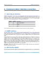
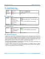
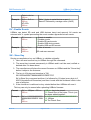
4. Communication Interface selection
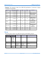
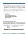
4.1. Selecting an Interface
USBwiz uses UART, SPI or I2C to communicate with any external microcontroller. At
power up, USBwiz samples MODE0 and MODE1 to determine what interface to use. The
MODE pins have a built in pull up resistors to default the pin to 1. Do not connect these
pins to VCC, leave unconnected for 1 or connect to GND for 0.
MODE0
0
1
0
1
MODE1
0
0
1
1
Interface
Force boot loader. *
I2C
UART
SPI
* In this mode the boot loader will not execute the firmware and will run UART at 9600 baud.
4.2. UART Interface
In UART mode, UART_TX pin is used to send data/responses to your microcontroller and
UART_RX pin to receive commands/data from your microcontroller. The default baud rate
for UART is 9600 baud, 8-bit, no parity and 1 stop bit. USBwiz can be set to different baud
rates.
CTS and RTS lines must be used in high band width applications. CTS pin is an input to
USBwiz. When it is high USBwiz will not send data and will wait for CTS to go low. CTS
should be low as long as possible to not slow down USBwiz. RTS pin is an output from
USBwiz and it is set high when USBwiz FIFO is near full. Depending on data transfer
speed, RTS pin may never go high because USBwiz is contentiously emptying the FIFO.
Note: The internal UART has hardware TX FIFO that is 16 byte long. After asserting CTS,
USBwiz may still send the internal FIFO, up to 16 bytes.
Important: USBwiz will NOT send any data if CTS pin is high! If this pin is not used then it
must be connected to ground.
4.3. SPI Interface Mode
In SPI mode six pins are used for communication to implement slave SPI, including two
Rev.2.27
Page 13 of 64
www.ghielectronics.com
GHI Electronics,LLC
USBwiz User Manual
Communication Interface selection
pins for handshaking. SPI_SSEL, SPI_SCK, SPI_MISO, and SPI_MOSI are the standard
SPI pins where SSEL is used for Slave Select, SCK is the Serial Clock (7Mhz running and
1.75Mhz for boot loader,) MISO is the data line going from USBwiz to your microcontroller,
and MOSI is the data line going from your microcontroller to USBwiz. The other two pins
are used for handshaking, they are DATARDY and BUSY. DATARDY pin goes high when
there is data in the USBwiz SPI buffer. When BUSY is high a user must not send any new
data to USBwiz.
The boot loader in SPI is half duplex. When DATARDY pin is high, USBwiz will not accept
any commands and will assume the SPI transaction is for reading the data; therefore, the
incoming data will be discarded. The other handshaking pin is BUSY. Before sending any
command to USBwiz this pin must be checked and data can be sent only when BUSY pin
is low.
On the other hand, the firmware runs SPI in full duplex mode. When SPI is full duplex,
USBwiz will accept any incoming data while it is sending simultaneously. If USBwiz has no
data to send back, it will send NDT (No Data Token.) The NDT is 0xff and is completely
ignored by USBwiz and should be ignored by your system as well. When reading data
from USBwiz but there is nothing to send, use NDT.
In some rare cases, there could be a need to send 0xFF (writing the hex value 0xFF, not
ASCII 0xFF!!) This is resolved by using HDT (Half Data Token.) HDT is the value 0xFE.
Whenever USBwiz or your system sees HDT, it must wait for one more byte to decide
what that value actually is. HDT followed by another HDT results in 0xFE; otherwise, it is
0xFF. Keep in mind 0xFF is always ignored even if it came after HDT.
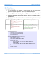
Here is a simple ‘C’ code example:
Note that this example ignores the incoming data from SPI and it shouldn’t be used.
SendData(char c)
{
if( c == 0xFF )
{
SendSPI(0xFE);
SendSPI(0);
}else if (c == 0xFE )
{
SendSPI(0xFE);
SendSPI(0xFE);
}else
SendSPI(c);
}
Important: USBwiz requires the following in order for SPI to work:
●
SCK is output from your system
Rev.2.27
Page 14 of 64
www.ghielectronics.com
GHI Electronics,LLC
USBwiz User Manual
Communication Interface selection
●
SCK is idle high
●
SCK is lower that 7Mhz. (1.75 in boot loader)
●
Data is shifted out MSB first
●
Data is shifted on the rising edge
For further details and timing diagrams, consult LPC2134 datasheet and manual from NXP
Semiconductor.
4.4. I2C Interface Mode
Four pins are needed for I2C communication. The USER_I2C_SCL and USER_I2C_SDA
are the two I2C bus lines. I2C_DATARDY and I2C_BUSY lines work exactly the same way
as SPI_DATARDY and SPI_BUSY work. USBwiz runs in slave I2C mode always. The
slave address of USBwiz is 0xA4. This address is fixed and can’t be changed.
Rev.2.27
Page 15 of 64
www.ghielectronics.com
GHI Electronics,LLC
USBwiz User Manual
Getting Started with USBwiz
5. Getting Started with USBwiz
The following chapter give simple steps to get USBwiz working for first time user and that
is through UART interface.
All you need:
●
USBwiz OEM board
●
RS232 adapter connected to UART Tx/Rx and connected to PC COMx
●
PC COMx access through a terminal program
●
USBwiz latest firmware
Step-by-Step:
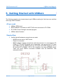
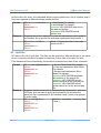
1. confirm that all hardware connections are made:
Rev.2.27
○
MODE pins are set to UART mode
○
Power is connected
○
RS232 adapter signals connections and let's assume it is connected to PC
COM4. If CTS and RTS signals are not available, user can ground CTS. Note
that USBwiz and the OEM boards are TTL levels and UART signals are 0V to
5V, but the PC is RS232 -12V to 12V, therefore, you need a RS232 circuit.
There are some RS232 converters available such as MAX3232. See
schematic below:
Page 16 of 64
www.ghielectronics.com
GHI Electronics,LLC
USBwiz User Manual
Getting Started with USBwiz
Other options are using USB to UART modules or cables. You will have a virtual
COM port on your PC that communicates with USBwiz. Examples are UM232R
and TTL-232R from FTDI.
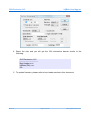
2. Open COM port using a terminal program, for example TeraTerm, and ensure the
baud rate is 9600, 8 data bits, 1 stop bit and no handshaking.
3. Select to receive a line end with the line feeds (LF+CR), because USBwiz only
sends CR. For transmitting, only CR should be sent.
Rev.2.27
Page 17 of 64
www.ghielectronics.com
GHI Electronics,LLC
USBwiz User Manual
Getting Started with USBwiz
4. Reset the chip and you will get the GHI electronics banner similar to the
following:
GHI Electronics, LLC
-----------------------------Boot Loader x.xx
USBwiz(TM) x.xx
!00
5. To update firmware, please refer to boot loader section in this document.
Rev.2.27
Page 18 of 64
www.ghielectronics.com
GHI Electronics,LLC
USBwiz User Manual
Getting Started with USBwiz
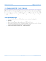
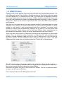
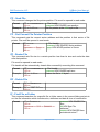
μPICFAT™ Development Board
For even easier and faster startup, GHI offers a development system for μALFAT and
USBwiz. This is the component that provides power and communication to
μALFAT/USBwiz. It also provides the serial interface to your computer, and contains the
PIC micro controller PIC18F453 that will be used to interface to μALFAT/USBwiz.
Complete with a programming port for direct interface to the ICD 2™ programmer.
UPICFAT provides both 3.3V and 5.0V.
Rev.2.27
Page 19 of 64
www.ghielectronics.com
GHI Electronics,LLC
USBwiz User Manual
1. USBwiz Functions
6. 1. USBwiz Functions
6.1. Commander
The commands and response in USBwiz are made in a way where they can be
understood and read by a human and can be easily parsed by any simple 8-bit micro.
Each command is 2 characters. Some commands take parameters and others don’t. For
example, VR command doesn’t take any parameters and it returns the version number. On
the other hand, MD requires parameter to run. MD creates (makes) a folder on the
accessed media device. ‘MD LOG’ creates a folder with the name LOG.
Note: Commands has specific format, please refer to USBwiz Command Set.
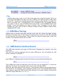
6.2. FAT Storage Media
USBwiz can connect to two kinds of storage media types. The media types are SD/MMC
cards and USB Mass Storage device (SCSI command subclass, bulk only protocol) which
includes thumb flash, USB hard drives and card readers. USBwiz supports three
simultaneous FAT devices. Keep in mind that all devices must be formatted FAT12, FAT16
or FAT32.
USBwiz can mount up to 3 File System Medias that are independent from each other,
which means that all opened files and operations in one file system has no effect on the
others. This gives USBwiz very great capability of flexible switching between the file
system Medias and providing other valuable functions like reading from file in one Media
and writing back in other file in another media at the same time.
To access FAT Storage Media, the media need to be mounted using FAT Mount command.
Once the device is mounted, you can use any of the file access commands.
Example: Mount File System on SD/MMC:
FM S
MD FOLDER
Directories (Folders)
Folders are supported by USBwiz. Use Change Directory command (CD) to change
Folders.
Rev.2.27
Page 20 of 64
www.ghielectronics.com
GHI Electronics,LLC
USBwiz User Manual
1. USBwiz Functions
MD USBWIZ
CD USBWIZ
Create “USBWIZ” folder
Change the current folder access to “USBWIZ” folder
Files
USBwiz allows you to open up to 4 files at the same time using file handles. This is not
how many files USBwiz can open on a drive. USBwiz can open thousand of files same
as your PC. Handles are used for fast access to a file. If a user needs to log data to 2
files at the same time, “VOLTAGE.LOG” and “CURRENT.LOG” file handles become
very useful. To do so, open VOLTAGE.LOG under handle 1 and CURRENT.LOG under
handle 2. Now start sending your data to handle 1 and 2 instead of the file name.
Handles can even point to files on different medias because USBwiz contains three
independent FAT cores.
6.3. USB Mass Storage
USBwiz has an internal USB Mass Storage Driver that can control two Mass Storage
Devices at the same time. In case there is a requirement to access a LUN, FM command
can be used with the LUN extension. FM p>l where p is the port number and l is the LUN
number. FM p command alone will use LUN0
FM 0
6.4. USB Human Interface Device
This USB class includes vast range of HID devices. Examples are: joysticks, mice and
keyboards.
First, the HID must be registered like any other USB device. We will initialize the HID
which is attached to USB port 1:
UH 1
Now USBwiz is ready get data from the HID which can be performed by Read HID:
HR 1
Then USBwiz will output the data size of the HID. Now, we can repeat HR 1 to read more
data from the device. It is normal for HR to return code “HID_NO_DATA”.
When the user read data from HID devices, it can represent different things depending on
the HID device. For example, it can represent a mouse move or a keyboard button press.
Your reference should be USB Device Class Definition for Human Interface Devices and
USB HID Usage Table from www.usb.org
Rev.2.27
Page 21 of 64
www.ghielectronics.com
GHI Electronics,LLC
USBwiz User Manual
1. USBwiz Functions
Keyboard
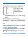
Most keyboards return 8 bytes in the HID report which are decoded as follows:
First byte is the modifier byte: (When the bit is set, the associated button is pressed)
Modifier Key
Left CTRL
Left SHIFT
Left ALT
Left GUI
Right CTRL
Right SHIFT
Right ALT
Right GUI
Bit Order
0
1
2
3
4
5
6
7
Key array bytes follows with each byte represent a pressed key. Thus, several pressed
keys can be reported at the same time. When many keys are pressed and the keyboard
cannot handle them, it will return an error in the HID report. Here are the codes for the
keys in this array:
Usage
ID
(Hex)
00
Usage Name
Remarks
01
Reserved (no event indicated)
Keyboard ErrorRollOver
Status indicator, Not a physical Button
Status indicator, Not a physical Button
02
Keyboard POSTFail
Status indicator, Not a physical Button
03
Keyboard ErrorUndefined
Status indicator, Not a physical Button
04
05
Keyboard a and A
remapped for other languages
06
07
Keyboard c and C
08
Keyboard e and E
09
Keyboard f and F
0A
Keyboard g and G
0B
Keyboard h and H
0C
Keyboard i and I
0D
Keyboard j and J
0E
Keyboard k and K
0F
Keyboard l and L
10
11
Keyboard m and M
12
Keyboard o and O
remapped for other languages
13
Keyboard p and P
remapped for other languages
14
15
Keyboard q and Q
Keyboard r and R
Keyboard s and S
Keyboard t and T
remapped for other languages
16
17
Rev.2.27
Keyboard b and B
remapped for other languages
Keyboard d and D
remapped for other languages
Keyboard n and N
remapped for other languages
Page 22 of 64
www.ghielectronics.com
GHI Electronics,LLC
USBwiz User Manual
1. USBwiz Functions
18
Keyboard u and U
19
1A
1B
1C
1D
1E
1F
20
21
22
23
24
25
26
27
Keyboard v and V
Keyboard w and W
Keyboard x and X
Keyboard y and Y
Keyboard z and Z
Keyboard 1 and !
Keyboard 2 and @
Keyboard 3 and #
Keyboard 4 and $
Keyboard 5 and %
Keyboard 6 and ^
Keyboard 7 and &
Keyboard 8 and *
Keyboard 9 and (
Keyboard 0 and )
Keyboard Return (ENTER)
28
29
2A
2B
Keyboard ESCAPE
Keyboard DELETE (Backspace)
Keyboard Tab
2C
2D
2E
2F
30
31
32
33
34
35
36
37
38
39
3A
3B
3C
3D
3E
3F
40
41
42
43
44
45
Keyboard Spacebar
Keyboard - and (underscore)
Keyboard = and +
Keyboard [ and {
Keyboard ] and }
46
47
48
Rev.2.27
Keyboard \ and |
Keyboard Non-US # and ~
Keyboard ; and :
Keyboard ‘ and “
Keyboard Grave Accent and Tilde
Keyboard, and <
Keyboard . and >
Keyboard / and ?
Keyboard Caps Lock
remapped for other languages
remapped for other languages
remapped for other languages
remapped for other languages
remapped for other languages
remapped for other languages
remapped for other languages
remapped for other languages
remapped for other languages
remapped for other languages
remapped for other languages
remapped for other languages
remapped for other languages
remapped for other languages
Keyboard Enter and Keypad Enter generate different
Usage codes
remapped for other languages
remapped for other languages
remapped for other languages
remapped for other languages
remapped for other languages
remapped for other languages
remapped for other languages
remapped for other languages
remapped for other languages
remapped for other languages
Keyboard F1
Keyboard F2
Keyboard F3
Keyboard F4
Keyboard F5
Keyboard F6
Keyboard F7
Keyboard F8
Keyboard F9
Keyboard F10
Keyboard F11
Keyboard F12
Keyboard PrintScreen
Keyboard Scroll Lock
Keyboard Pause
Page 23 of 64
www.ghielectronics.com
GHI Electronics,LLC
USBwiz User Manual
1. USBwiz Functions
49
4A
4B
4C
4D
4E
4F
50
51
52
53
54
55
56
57
58
Keyboard Insert
Keyboard Home
Keyboard PageUp
Keyboard Delete Forward
Keyboard End
Keyboard PageDown
Keyboard RightArrow
Keyboard LeftArrow
Keyboard DownArrow
Keyboard UpArrow
Keypad Num Lock and Clear
Keypad /
Keypad *
Keypad Keypad +
Keypad ENTER
59
5A
5B
5C
5D
5E
5F
Keypad 1 and End
Keypad 2 and Down Arrow
Keypad 3 and PageDn
Keypad 4 and Left Arrow
Keypad 5
Keypad 6 and Right Arrow
Keypad 7 and Home
60
61
62
63
Keypad 8 and Up Arrow
Keypad 9 and PageUp
Keypad 0 and Insert
Keypad . and Delete
Keyboard Non-US \ and |
Keyboard Application
Keyboard Power
Keypad =
Keyboard F13
Keyboard F14
Keyboard F15
Keyboard F16
Keyboard F17
Keyboard F18
Keyboard F19
Keyboard F20
Keyboard F21
Keyboard F22
Keyboard F23
Keyboard F24
Keyboard Execute
Keyboard Help
Keyboard Menu
Keyboard Select
Keyboard Stop
Keyboard Again
64
65
66
67
68
69
6A
6B
6C
6D
6E
6F
70
71
72
73
74
75
76
77
78
79
Rev.2.27
Keyboard Enter and Keypad Enter generate different
Usage codes
Page 24 of 64
www.ghielectronics.com
GHI Electronics,LLC
USBwiz User Manual
1. USBwiz Functions
7A
7B
7C
7D
7E
7F
80
81
82
83
84
85
86
8A
8B
8C
8D
8E
8F
90
91
92
93
94
95
96
97
98
99
9A
9B
9C
9D
9E
9F
A0
A1
A2
A3
A4
A5-CF
B0
B1
B2
B3
B4
B5
B6
B7
Rev.2.27
Keyboard Undo
Keyboard Cut
Keyboard Copy
Keyboard Paste
Keyboard Find
Keyboard Mute
Keyboard Volume Up
Keyboard Volume Down
Keyboard Locking Caps Lock
Keyboard Locking Num Lock
Keyboard Locking Scroll Lock
Keypad Comma
Keypad Equal Sign
Keyboard International4
Keyboard International5
Keyboard International6
Keyboard International7
Keyboard International8
Keyboard International9
Keyboard LANG1
Keyboard LANG2
Keyboard LANG3
Keyboard LANG4
Keyboard LANG5
Keyboard LANG6
Keyboard LANG7
Keyboard LANG8
Keyboard LANG9
Keyboard Alternate Erase
Keyboard SysReq/Attention
Keyboard Cancel
Keyboard Clear
Keyboard Prior
Keyboard Return
Keyboard Separator
Keyboard Out
Keyboard Oper
Keyboard Clear/Again
Keyboard CrSel/Props
Keyboard ExSel
Reserved
Keypad 00
Keypad 000
Thousands Separator
Decimal Separator
Currency Unit
Currency Sub-unit
Keypad (
Keypad )
Page 25 of 64
www.ghielectronics.com
GHI Electronics,LLC
USBwiz User Manual
1. USBwiz Functions
B8
B9
BA
BB
BC
BD
BE
BF
C0
C1
C2
C3
C4
C5
C6
C7
C8
C9
CA
CB
CC
CD
CE
CF
D0
D1
D2
D3
D4
D5
D6
D7
D8
D9
DA
DB
Keypad {
Keypad }
Keypad Tab
Keypad Backspace
Keypad A
Keypad B
Keypad C
Keypad D
Keypad E
Keypad F
Keypad XOR
Keypad ^
Keypad %
Keypad <
Keypad >
Keypad &
Keypad &&
Keypad |
Keypad ||
Keypad :
Keypad #
Keypad Space
Keypad @
Keypad !
Keypad Memory Store
Keypad Memory Recall
Keypad Memory Clear
Keypad Memory Add
Keypad Memory Subtract
Keypad Memory Multiply
Keypad Memory Divide
Keypad +/Keypad Clear
Keypad Clear Entry
Keypad Binary
Keypad Octal
DC
DD
DEDF
E0
E1
E2
Keypad Decimal
Keypad Hexadecimal
E3
E4
E5
E6
E7
E8FFFF
Rev.2.27
Reserved
Keyboard LeftControl
Keyboard LeftShift
Keyboard LeftAlt
Keyboard Left GUI
Keyboard RightControl
Keyboard RightShift
Keyboard RightAlt
Keyboard Right GUI
Used if modifier byte is not supported
Used if modifier byte is not supported
Used if modifier byte is not supported
Used if modifier byte is not supported
Used if modifier byte is not supported
Used if modifier byte is not supported
Used if modifier byte is not supported
Used if modifier byte is not supported
Reserved
Page 26 of 64
www.ghielectronics.com
GHI Electronics,LLC
USBwiz User Manual
1. USBwiz Functions
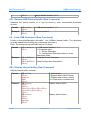
Example: This example is taken from USB HID specifications. It assumes a 4-bytes
HID report for a keyboard:
Key Event
None
Modifier Byte
00000000B
Array
00H
Array
Array
00H
00H
RALT down
01000000
00
00
00
None
01000000
00
00
00
A down
01000000
04
00
00
X down
01000000
04
1B
00
B down
01000000
04
05
1B
Q down
01000000
01
01
01
A up
01000000
05
14
1B
B and Q up
01000000
1B
00
00
None
01000000
1B
00
00
RALT up
00000000
1B
00
00
X up
00000000
00
00
00
Comment
Report current key
state even when no
new key events.
Report order is
arbitrary and does
not reflect order of
events.
Phantom state.
Four Array keys
pressed. Modifiers
still reported.
Multiple events in
one report. Event
order is
indeterminate.
Mouse
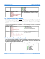
Most mice return 4 bytes in the HID report which are decoded as follows:
Byte0
5 bits
3 bits
Reserved
Buttons
b0 left
b1 right
b2
middle
Constant
Variable
NULL
Absolute
0
Rev.2.27
Up=0
Down=1
Byte1
Byte2
Byte3
X position
Y position
Scroll Position
Variable
Relative to
the last
position
-127 +127
Variable
Relative to
the last
position
-127 +127
Variable
Relative to the last
position
Page 27 of 64
-127 +127
www.ghielectronics.com
GHI Electronics,LLC
USBwiz User Manual
1. USBwiz Functions
6.5. USB Printers
USBwiz Printer driver support those that have interface with unidirectional protocol. The
way USB printers work is very similar to Parallel port printers. But instead of the data going
over the Parallel port, it is transferred over USB. This means that the application needs to
know what data/scripts to be sent to the printer. USBwiz sends the data to the Printer as-is
where the user's application needs to use appropriate printer scripting, just like in Parallel
Port printers. Some of the printers scripts include PCL (from HP), ESC-P (from Epson.),
and Postscript.
Note that low cost printers do not have any available scripting. Sometimes these are called
“Windows only” printers. The reason behind the low cost is that the processor on these
printers is very simple, it gets pre-processed data from windows. The printer driver
software is actually what processes the image/text on the host PC and then sends final
data to the printer. These printers can't be used with USBwiz unless specifications are
provided by the manufacture, which are usually proprietary and very hard to obtain.
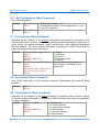
There is an easy way to test any USB printer, including those ones that do not have scripts
support. First, we need the printer connected to a Windows PC with installed drivers.
Create any simple document (small text file) on the PC and click print. This will bring up
the “Print” window. On the drop-down menu, select the printer you need to test with
USBwiz and then make sure you click the check-box “Print to file” as shown below.
Click “OK” and windows will prompt for a file name and location. Save the file anywhere
you like. This file contains a processed data for the printer you selected earlier. Now, all we
have to do is transfer the file to the printer using USBwiz.
Disconnect the printer from the PC and connect it to USBwiz. The file we generated earlier
can go on an SD card or USB drive.
First command to be used is USB register printer UP:
Rev.2.27
Page 28 of 64
www.ghielectronics.com
GHI Electronics,LLC
USBwiz User Manual
1. USBwiz Functions
UP 0
Now you can preform any printer commands, such as reset.
PR 0
The actual print command PP, will accept up to 255 bytes of data for every transfer. You
can safely call the PP more than once.
PP 0>4
Get Printer Status Command PS is used to Get Printer Standard Status Byte which is
identical to status byte that is usually returned from Parallel Port printers.
6.6. USB Serial Devices
USBwiz supports many serial USB devices. Communication Device Class (CDC) is one of
them. This can be a USB modem or a cell phone. AT commands can be used to dial
numbers, send SMS messages and transfer data on some of the CDC USB modems.
Check your cellphone manual for a list of supported AT commands. Other serial devices
are Prolific, Silabs and FTDI serial (UART) to USB converters. Most USB GPS modems
out there use Prolific chipset. This allows you to connect a USB GPS to USBwiz. Same for
Silabs and FTDI chipsets. Many devices use one of these chips and therefore they can
communicate with USBwiz as easy as any other USB devices.
US 0>F>2850
SW 0>4
Register an FTDI device at port 0
Send 1234 to FTDI
6.7. Raw USB Access
Accessing a USB device is divided into three stages:
1. Enumeration stage: Includes USB addressing.
2. Learning Stage: Querying about the USB device and performing the required setup.
(Setup transfers, opening Pipes, ...).
3. Read/Write Pipes stage.
Example: Accessing a USB mouse:
Stage 1:
Assign a device handle 0 for the connected device on port 0,
UI 0>0
Rev.2.27
Page 29 of 64
www.ghielectronics.com
GHI Electronics,LLC
USBwiz User Manual
1. USBwiz Functions
Stage 2:
Load device descriptor into the internal Buffer,
LD 0>D
This is an optional command, since it is only used to display the internal buffer contents,
DB A
Output: Device descriptor size + Device descriptor data in the internal buffer
Load the first configuration descriptor into the internal buffer,
LD 0>C0
This is an optional command, since it is only used to display the internal buffer contents,
DB A
Output: configuration descriptor size + configuration descriptor data in the internal
buffer.
Set the desired configuration which is, in this case, the first configuration,
SC 0>1
Note that using 0 means go back to addressing mode stage.
Find the specific Interface descriptor in the previously loaded Configuration descriptor in
the internal buffer,
FI 03 01 02 00
class =HID, subclass=bootable, protocol=mouse, index=the 1st found interface
descriptor that match this criteria.
Output: The found interface descriptor size + the data
It is also possible to use the following:
FI 03 FF FF 00
class=HID subclass=don't care, protocol=don't care, index=the 1st found interface
descriptor that match this criteria.
Output: The found interface descriptor size + the data.
We will get the same result, if the device is a USB mouse with no other HID interfaces.
Set the found Interface,
Rev.2.27
Page 30 of 64
www.ghielectronics.com
GHI Electronics,LLC
USBwiz User Manual
1. USBwiz Functions
SI
Find an Endpoint that belongs to the previously found Interface
FE 03 02
transfer= interrupt, direction= input
Output: found Endpoint descriptor size + the data
Open Pipe to the selected endpoint and assign handle 6 to it,
OP 6
It is also possible to search for any kind of descriptors in the loaded internal buffer using
the FD command,
Example: Find the 1st HID descriptor in a previously loaded configuration descriptor,
FD 21 00
Output:
!00
$09
09 21 10 01 00 01 22 34 00
!00
Stage 3:
Read 4 bytes from Pipe 6
RP 6>04
Close Pipe
CP 6
Also, using the Setup command, it is possible to send setup requests on the default
control pipe using the SS command,
Example: Get Device descriptor
SS device_handle>80 06 0100 0000 0012
Output:
0x12 0x01 0x10 0x01 0x00 0x00 0x00 0x08 0x2A 0x06 0x00 0x00 0x00
0x00 0x00
0x00 0x00 0x01
Rev.2.27
Page 31 of 64
www.ghielectronics.com
GHI Electronics,LLC
USBwiz User Manual
1. USBwiz Functions
Rev.2.27
Page 32 of 64
www.ghielectronics.com
GHI Electronics,LLC
USBwiz User Manual
USBwiz Command Set
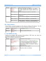
7. USBwiz Command Set
All commands below are entered in ASCII. We choose to use ASCII to simplify
troubleshooting and to allow humans to enter commands easily. A special case is when
accessing the data inside or outside a file. When writing/reading to/from a file or USB Pipe,
USBwiz will use any kind of data. Basically, what you send is what goes on the file. It
doesn’t have to be ASCII.
When USBwiz is done processing a command, it will return an error code in the form “!
xx<CR>” where xx is the error number. Also, some commands require returning some
extra information. Returned data will come after the symbol $, unless noted otherwise.
You can send multiple commands to USBwiz until its FIFO is full (indicated by BUSY or
RTS.) USBwiz will take the commands in one at the time, process them and send
responses for each one. Always terminate commands with carriage return character.
Command
Description
Command
Description
BL
Update Firmware
IT
Initialize Real Time Clock
ST
Set Real Time Clock
GT
Get Current Real Time Clock
VR
Get Version Number
BR
Set UART Baud Rate
RT
Reset Firmware
EE
Enable/Disable Echo
RS
Read Sector
WS
Write Sector
FM
Mount File System
DS
Device Switch
II
Get USB Device Info
UM
Register USB Mass Storage
SD
Initialize SD card
MS
Get Media Statistics
QF
Quick Format Media
IL
Initialize List Files and Folders
NF
Get Next Directory Entry
MD
Make Directory
CD
Change Directory
RD
Remove Directory
OF
Open a file for read, write or
append
CF
Close File Handle
FF
Flush File Data
RF
Read from File
WF
Write to File
SH
Shadow Write to multiple Files
RW
Read from File, Write to other
file
SF
Split file
PF
Seek File
FP
Get Current File Pointer
Position
Rev.2.27
Page 33 of 64
www.ghielectronics.com
GHI Electronics,LLC
USBwiz User Manual
USBwiz Command Set
Command
Description
Command
Description
ZF
Resize File
DF
Delete File
IF
Find File or Folder
ND
Rename File or Folder
UH
Register USB Human
Interface Device
HR
Read HID Report
UP
Register USB Printer
PR
Reset USB Printer
PS
Get USB Printer Status
PP
Send Data to USB Printer to
print
US
Register Serial
Communication Device
SR
Read Serial Device
SW
Write to Serial Device
EV
Enable Events
SK
Store Key
CK
Check Key
TF
Print File
UI
Enumerate USB Device
UR
Release USB Device Handle
LD
Load USB Descriptor
DB
Display Internal buffer
SC
Set Configuration
FI
Find Interface
SI
Set Interface
FE
Find Endpoint
FD
Find Descriptor
SS
Send Setup Request
OP
Open USB Pipe
CP
Close Pipe Handle
RP
Read Pipe
WP
Write Pipe
Notes on commander:
●
Any command must not exceed 38 bytes and must be terminated with a carriage
return.
●
The user must read back the responses for each command properly and check
whether the command was successful.
●
The command format must be followed with the same number of arguments. Also,
extra spaces count as errors.
●
All numbers are Hexadecimal represented in ASCII. For example, to send the
decimal number 16 to USBwiz which is 10 in Hexadecimal, you send 0x31 which is
ASCII for 1 and 0x30 which is ASCII for 0. Also, for Hexadecimal numbers A to F,
they must be entered in upper case letters.
●
In all command's output description below, will assume the commands succeeded.
n case of failure, the command would return an error code instead of success and
alt. In other words, in any command, a !00 denotes success and the command can
resume operation. But in case of failure, the error code is !xx, where xx is the error
number and then the current command halt and the commander resume processing
Rev.2.27
Page 34 of 64
www.ghielectronics.com
GHI Electronics,LLC
USBwiz User Manual
USBwiz Command Set
further commands.
●
Some commands have multiple error codes !xx, usually, the first error code denotes
the command is accepted and then it is processed. Another error code is sent when
the command has finished processing successfully. This is useful, because some
commands can take some time to finish, so the first error can note that the
command is accepted and then the user can do other application processing and
then return to read the final error code.
●
Below, data sent to USBwiz are BLACK and data received are RED. <CR> is a
carriage return which is the Enter key on a keyboard, ASCII value 0x0D or in C
language '\r'. <SP> is a space which is ASCII value 0x20.
●
File/Folder names has a certain format and certain accepted characters according
to the FAT File System. USBwiz supports Earlier FAT File Systems used short file
names (noted as 8.3) which have the following features:
○
ASCII format
○
Only capital letters
○
Maximum of 8 characters for the file name
○
Maximum of 3 characters for the file extension
○
No spaces are allowed
○
Only one dot is allowed preceding the file extension
○
Numbers are allowed
○
The following characters are allowed: $ % ' - _ @ ~ ` ! ( ) { } ^ # &
BL - Update Firmware Using Boot Loader
Updates USBwiz firmware. The firmware can be updated from the Boot Loader or from
the firmware using this command.
Upon initiating the command, USBwiz switches to Boot Loader mode and updates the
firmware automatically. For details on updating the firmware, please consult the
description for the Boot Loader and updating the firmware.
Format
Example
Rev.2.27
BL<SP>d<CR>
Switches to
Bootloader
mode and
updates
automatically
BL<SP>0<CR>
d The device type and can be S for SD or 0/1
for the USB port number
Load new firmware from USB memory on port
0
Page 35 of 64
www.ghielectronics.com
GHI Electronics,LLC
USBwiz User Manual
USBwiz Command Set
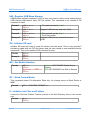
IT - Initialize Real Time Clock
USBwiz has a built in real time clock that is used to save the date on the created files.
Users need to specify if USBwiz will be running the RTC using the same oscillator as
USBwiz or separate 32Khz oscillator and a battery. The advantage of running the RTC
on a 32Khz oscillator and battery is that it will not loose the time when losing the main
power source of USBwiz.
Format
IT<SP>t<CR>
!00<CR>
Example
IT<SP>S<CR>
!00<CR>
t The mode to run RTC on. Can be B for backup
battery or S for share mode with the oscillator
used for USBwiz.
Run RTC clock from same oscillator and power as
USBwiz.
ST - Set Real Time Clock
After the time is set, the RTC inside USBwiz will keep track of the time. The accuracy of
the RTC is 2 seconds.
Format
Example
ST<SP>t<CR>
!00<CR>
ST<SP>34210000<CR>
!00<CR>
t The time and date as 32 bits that is
formed as in the structure below.
Set clock to 1/1/2006 00:00:00
* Time and Date structure is a 32-bits standard structure used in FAT system. For
example, 0x34212002 is 01/01/2006 – 04:00:04
0x34212000 Bits in Binary
Bits(s)
Field
Description
31..25
Year1980 Years since 1980
24..21
Month
1..12
0001
20..16
Day
1..31
0 0001
15..11
Hour
0..23
0 0100
10..5
Minute
0..59
00 0000
4..0
Second2
Seconds divided by 2 (0..30)
001 1010
0 0010
GT - Get Current Real Time Clock
Obtains the current time. Returned value can be a 32-bit hex number or an ASCII string.
Format
Rev.2.27
GT<SP>f<CR>
!00<CR>
(DWORD or ASCII string time
data)<CR>
!00<CR>
Page 36 of 64
f Returned data can be 32bit hex (value X) or
formatted ASCII string
(value F)
www.ghielectronics.com
GHI Electronics,LLC
USBwiz User Manual
USBwiz Command Set
Example 1
Example 2
GT<SP>F<CR>
!00<CR>
01/20/2006<SP>-<SP>06:21:04<CR>
!00<CR>
GT<SP>X<CR>
!00<CR>
$34210000<CR>
!00<CR>
Get time in formatted ASCII
format.
Get time in DWORD HEX.
VR - Get Version Number
It prints the version number of USBwiz firmware. Note that this version is not same or
related to the version number of the boot loader nor the OEM boards we offer.
Format
Example
VR<CR>
M Major number
USBwiz<SP>M.mm<CR> mm minor number
!00<CR>
VR<CR>
USBwiz<SP>2.28<CR>
!00<CR>
BR - Set UART Baud Rate
UART defaults to 9600 at power up. This is extremely slow but some systems don’t
support faster bauds. The baud rate can be set to many different standard baud rates.
BR command sets the internal divider registers of the UART hardware. This way any
possible baud rate can be set. To calculate the divider value use (OSC*4/BaudRate/16)
The OSC we use on USBwiz is 14745600. The baud rate value is lost on reset and
UART goes back to 9600.
Format
BR<SP>vvvv<CR>
!00<CR>
Example
BR<SP>0020<CR>
!00<CR>
Some common values:
Baud Rate
9600
19200
38400
57600
115200
921600
vvvv: WORD HEX Baud Rate
Divider
Baud Rate is 115200
Divider in decimal
384
192
96
64
32
4
Divider in HEX
0180
00C0
0060
0040
0020
0004
RT - Reset Firmware
Format
Rev.2.27
RT<SP>OK<CR>
Page 37 of 64
www.ghielectronics.com
GHI Electronics,LLC
USBwiz User Manual
USBwiz Command Set
EE - Enable/Disable Echo
To echo the sent data to USBwiz.
Format
EE<SP>h<CR>
!00<CR>
h can be 0 to disable echo
and 1 to enable echo
Example
EE<SP>1<CR>
!00<CR>
Enables echo
RS - Read Sector
Format
Example
RS<SP>msssssss<CR>
!00<CR>
512 Bytes is
returned in HEX
mode and (512*2 in
ASCII mode)
!00<CR>
RS<SP>H0<CR>
Read Sector from the current File System
Media
m Returned data mode. H for HEX and A for
ASCII.
ssssssss HEX DWORD sector address
Read Sector 0
WS - Write Sector
Format:
Example
WS<SP>ssssssss<CR>
!00<CR>
512 Bytes must be
sent to USBwiz
!00<CR>
WS<SP>0<CR>
Write to Sector from the current File System
Media
ssssssss HEX DWORD sector address
Write to Sector 0
FM - Mount File System
USBwiz can mount up to 3 File System Medias that are independent from each other,
which means that all opened files and operations in one file system have no effect on
the others. This gives USBwiz very great capability of flexible switching between the file
system Medias and providing other valuable functions like reading from file in one
Media and write it back in other file in another media at the same time.
FM takes the responsibility of mounting the dedicated File System and doing any
necessary USB commands for USB memory.
Currently USBwiz accesses the first primary partition of a storage media by default.
However, it can be forced into mounting the second primary partition which might be
useful on some systems (iPods for example).
Rev.2.27
Page 38 of 64
www.ghielectronics.com
GHI Electronics,LLC
USBwiz User Manual
USBwiz Command Set
Format
Example
FM<SP>d<CR>
!00<CR>
$mm<CR>
!00<CR>
FM<SP>d>l<CR>
Mount File System for device d
d can be S for SD, 0 for USB 0 or 1 for USB 1
mm Max available LUN on device, ($00) in most
cases.
Mount File System for device d and LUN l
FM <SP>d>>2<CR>
Mount File system on the second primary partition
of device d.
Mount device on USB port 0 and use default LUN
0
Mount device on USB port 1 and use LUN 4
FM<SP>0<CR>
FM<SP>1>4<CR>
FM<SP>0>>2<CR>
Mount device on USB port 0 and use default LUN
0. Skip partition 1 and mount primary partition 2.
DS - Device Switch
Device Switch command switches the file access to different File System. The FM
command automatically calls DS on the last successfully mounted media.
Format
Example
DS<SP>d <CR>
!00<CR>
DS<SP>S<CR>
!00<CR>
d Can be S, 0 or 1
Switch access to SD card
II - Get USB Device Info
Displays the available USB interfaces (functionalities). USB class, sub class and
protocol are displayed for each found interface.
Note: This command resets the device.
Format
Example
Rev.2.27
II<SP>p<CR>
!00<CR>
$vvvv>pppp>nn<CR>
$cc>ss>rr<CR>
!00<CR>
II<SP>0<CR>
!00<CR>
$1234>5678>1<CR>
$04>02>01<CR>
!00<CR>
Read device info on port p
Device vendor ID vvvv and product ID pppp.
nn: The found interfaces count. Then one or
more entries depending on the interfaces
count where cc class, ss subclass rr protocol
of the interface.
Read device info on port 0
This device has one interface.
Page 39 of 64
www.ghielectronics.com
GHI Electronics,LLC
USBwiz User Manual
USBwiz Command Set
UM - Register USB Mass Storage
USB Memory register command. Use it in case you need to read or write sectors from a
USB memory that doesn't have FAT file system. This command is not needed if FM
command is used.
Format1
Example1
Format2
Example2
UM<SP>p <CR>
!00<CR>
UM<SP>0<CR>
!00<CR>
UM<SP>p>l<CR>
!00<CR>
UM<SP>0>1<CR>
!00<CR>
p The port and can be 0 or 1
Register USB memory and use LUN 0
p The port and can be 0 or 1
l The LUN number
Register USB memory on port 0 and use
LUN1
SD - Initialize SD card
Initialize SD card and have it ready for sector read and write. This is only needed if
accessing media with no FAT file system and the user needs to use read/write sector
commands. This is not needed if FM command is used.
Format
Example
SD<CR>
!00<CR>
SD<CR>
!00<CR>
MS - Get Media Statistics
Format
MS<CR>
!00<CR>
$ssssssss<SP>$ffffffff<CR>
!00<CR>
ssssssss HEX DWORD Media Size In
Sectors
ffffffff HEX DWORD Free Size In Sectors
QF - Quick Format Media
This command cleans File Allocation Table only. No change occurs to Boot Sector or
MBR.
Format
QF<SP>CONFIRM FORMAT<CR>
IL - Initialize List Files and Folders
It sets List Files and Folders Function pointer to the first Directory entry in the current
root.
Format
Rev.2.27
IL<CR>
!00<CR>
Page 40 of 64
www.ghielectronics.com
GHI Electronics,LLC
USBwiz User Manual
USBwiz Command Set
NF - Get Next Directory Entry
This command will print out the Directory Entry “File or Folder” and increments the Files
and Folders list pointer.
Format
Example
NF<CR>
!00<CR>
NNNNNNNN.EEE<SP>AA<SP>
ssssssss<CR>
!00<CR>
NF<CR>
!00<CR>
TEST0001.TXT<SP>00<SP>
0000FE23<CR>
!00<CR>
NF<CR>
!00<CR>
TEST0002.TXT<SP>00<SP>
00001234<CR>
!00<CR>
NNNNNNNN File Name
EEE File Extension
AA HEX Byte File Attributes*
ssssssss HEX DWORD File
Size
Passing NF command two
times and get the results.
* File Attributes are one byte Standard Attribute Structure in FAT system.
7
6
Reserved
5
Archive
4
Folder
3
Volume
ID
2
System
1
Hidden
0
Read Only
MD - Make Directory
Creates a folder in the current directory ( folder ).
Format
Example
MD<SP>foldername<CR>
!00<CR>
MD<SP>MYFOLDER<CR> Create a folder with name
!00<CR>
MYFOLDER
CD - Change Directory
Changes the current folder access. Folder must exist.
Format
Example
CD<SP>foldername<CR>
!00<CR>
CD<SP>MYFOLDER<CR>
!00<CR>
RD - Remove Directory
This command removes directory. The directory must be empty from any files or
Rev.2.27
Page 41 of 64
www.ghielectronics.com
GHI Electronics,LLC
USBwiz User Manual
USBwiz Command Set
subdirectories.
Format
Example
RD<SP>foldername<CR>
!00<CR>
RD<SP>MYFOLDER<CR>
!00<CR>
Remove the folder with name
MYFOLDER
OF - Open a file for read, write or append
To open a file for read, write or append in the current Folder, use OF command. The
command require a file handle and the access mode.
Open Modes are:
●
‘R’ Open for read, requires the file to already exist in the current media and the
current accessed folder.
●
‘W’ Open for write, will create a new file and give write privilege to it. If the file
already exists, it will be erased first then will open a new one for write.
●
‘A’ Open for append, will create a new file and give write privilege to it. If the file
already exists, it will append data to the end.
Note: USBwiz has 4 available file handles. This is the number of files that can be open
at any time and is not related to the number files USBwiz can access. USBwiz is able
access unlimited number of files.
Format
OF<SP>nM>filename<CR>
!00<CR>
Example
OF<SP>1R>VOLTAGE.LOG<CR>
!00<CR>
OF<SP>0W>CURRENT.LOG<CR>
!00<CR>
Open file foldername with file
handle n and access mode M
M can be R,W or A
n can be 0, 1, 2 or 3
Open file VOLTAGE.LOG with file
handle 1 with read access mode.
Open file CURRENT.LOG with file
handle 0 with write access mode.
FF - Flush File Data
Flushes the opened file. All buffered data will be written to the storage media. The file
will still be opened and associated with a handle, after performing this operation. This
command is useful to make sure all data are written to the media when needed.
If any data is written to a file, the file must be flushed (or closed – CF command) when
done. Otherwise, the file and/or the file system might get corrupted.
Format
Rev.2.27
FF<SP>n<CR>
!00<CR>
Flush File handle n
Page 42 of 64
www.ghielectronics.com
GHI Electronics,LLC
USBwiz User Manual
USBwiz Command Set
CF - Close File Handle
This command issues a flush file (FF – Command) automatically and then closes the file
handle. Afterwards, the handle will available for future use.
Format
CF<SP>n<CR>
!00<CR>
Close File handle n
RF - Read from File
After opening a file, any amount of data can be read using this command. To read more
data, send another RF command and so on. If all requested data is not available
(reached file end), USBwiz will pad the output with a filler byte given by the user.
When reading, the data is sent directly to the user with no formatting (no interpretation
or conversion).
Format
Example
RF<SP>nM>ssssssss<CR> n File Handle
!00<CR>
M Filler Character
ssssssss Bytes is
ssssssss HEX DWORD desirable data
returned
size to be read
$aaaaaaaa<CR>
aaaaaaaa HEX DWORD actual read data
!00<CR>
from file size
We have a file with 8 bytes (ABCDEFGH) in it, and it is opened for
read with handle number 2.
RF<SP>2Z>5<CR>
!00<CR>
ABCDE
$00000005<CR>
!00<CR>
RF<SP>2Z>5<CR>
!00<CR>
FGHZZ
$00000003<CR>
!00<CR>
Read 5 bytes twice from a file handle 2
with filler Z
WF - Write to File
After opening a file, any amount of data can be written using this command. To write
more data, send another WF command and so on. Note that if first error code is not !00
(an error occurred), the command would halt and further commands are processed, so
sending the file data upon an error code would result in the data being not being written
and processing these data as commands.
When writing, the sent data is written directly to the file with no formatting (no
interpretation or conversion). Also, when requesting to write a certain amount of bytes,
Rev.2.27
Page 43 of 64
www.ghielectronics.com
GHI Electronics,LLC
USBwiz User Manual
USBwiz Command Set
all of them must be sent; if an error occurs while writing, USBwiz still expects all bytes
before producing the final error code.
If any data is written to a file, the file must be flushed (FF command) or closed (CF
command) when done. Otherwise, the file and/or the file system might get corrupted.
Format
Example
WF<SP>n>ssssssss<CR>
!00<CR>
User sends data
$aaaaaaaa<CR>
!00<CR>
WF<SP>1>10<CR>
!00<CR>
1234567890abcdef
$00000010<CR>
!00<CR>
n File Handle
ssssssss HEX DWORD data size to be
written
aaaaaaaa HEX DWORD actual written
size
Write 16 bytes to the file opened with
handle 1
SH - Shadow Write to multiple Files
This command is similar to WF command except that it writes the same data into two or
three files simultaneously.
Format 1
SH<SP>n<SP>m>ssssssss<CR>
!00<CR>
User sends data
$aaaaaaa1 !00<CR>
$aaaaaaa2 !00<CR>
Format 2
SH<SP>n<SP>m<SP>o>ssssssss<CR>
!00<CR>
User sends data
$aaaaaaa1 !00<CR>
$aaaaaaa2 !00<CR>
$aaaaaaa3 !00<CR>
SH<SP>1<SP>0<SP>3>10<CR>
!00<CR>
1234567890abcdef
$00000010 !00<CR>
$00000010 !00<CR>
$00000010 !00<CR>
Example
N First File Handle
m Second File Handle
ssssssss HEX DWORD data
size to be written
aaaaaaaa HEX DWORD actual
written data size to the first and
second handles
Same as the previous Format
except for having a third
shadow o Which is a third file
handle
Write 16 bytes to the files
opened with handles 1, 0, 3
USBwiz accepted the command
16 bytes of data to go into the
file
USBwiz was able to write 16
bytes to the three files
successfully with no errors
occurrence.
RW - Read from File, Write to other file
This command is very powerful and fast! If we have two files, one is opened for Read
Rev.2.27
Page 44 of 64
www.ghielectronics.com
GHI Electronics,LLC
USBwiz User Manual
USBwiz Command Set
and the other for write, this command allows copying data from a file to another even if
they were opened in different storage media devices.
Format
Example
RW<SP>r<SP>w>ssssssss<CR>
!00<CR>
$aaaaaaaa<CR>
!00<CR>
r Read-Mode File Handle
w Write-Mode File Handle
ssssssss HEX DWORD data size to
be read and written
aaaaaaaa HEX DWORD actual
written size
Suppose that a file is opened for read and represented with handle 0
and another file is opened for write and represented with handle 1.
RW<SP>0<SP>1>100<CR>
!00<CR>
$aaaaaaaa<CR>
!00<CR>
Read 256 bytes from file 0 and write
them into file 1
SF - Split file
SF splits a file into 2 new files. The files can be opened on different drives or the same
drive. It requires one file to be open for read and 2 other files to be open for write.
Files handles will be automatically closed after successful execution of the command.
Format
Example
Rev.2.27
SF<SP>n>m+o@ssssssss<CR>
!00<CR>
$aaaaaaa1<CR>
!00<CR>
$aaaaaaa2<CR>
!00<CR>
n Source Read-Mode File Handle
m First part destination Write-Mode
File Handle
o Second part destination WriteMode File Handle
ssssssss HEX DWORD desirable
split position in the source file
aaaaaaa1 HEX DWORD actual
written data size to the first part file
aaaaaaa2 HEX DWORD actual
written data size to the second part
file
Suppose that the source file is represented by file handle 1 with size
32 Bytes. And we want to split it at the position 16 and save the
parts into files represented in file handles 0 and 2 which are opened
in write-mode.
SF<SP>1>0+2@10<CR>
Split file 1 at position 16 into two files
!00<CR>
0 and 2
$00000010<CR>
!00<CR>
$00000010<CR>
!00<CR>
Page 45 of 64
www.ghielectronics.com
GHI Electronics,LLC
USBwiz User Manual
USBwiz Command Set
PF - Seek File
This command changes the file pointer position. File must be opened in read mode.
Format
Example
PF<SP>n>ssssssss<CR>
!00<CR>
PF<SP>1>10<CR>
!00<CR>
n File Handle
ssssssss HEX DWORD new position
Set file pointer at the 16th byte in file
FP - Get Current File Pointer Position
This command gets the current sector address and the position in that sector of file
pointer. File must be opened in read mode.
Format
FP<SP>n<CR>
!00<CR>
$ssssssss<SP>$pppp<CR>
!00<CR>
n File Handle
ssssssss HEX DWORD Sector address
pppp HEX WROD position in Sector
ZF - Resize File
This command sets file size to a certain position less than its size and omits the data
after that position.
File must be opened in read mode.
File handle will be automatically closed after successfully executing this command.
Format
Example
ZF<SP>n>ssssssss<CR> n File Handle
!00<CR>
ssssssss HEX DWORD split size
ZF<SP>1>10<CR>
Resize the file to 16 bytes
!00<CR>
DF - Delete File
Format
Example
DF<SP>filename<CR>
!00<CR>
DF<SP>TEST.TXT<CR>
!00<CR>
IF - Find File or Folder
This command searches for a specific file or folder name in the current folder and prints
out the file information which includes size, attributes and date & time of modification.
Format
Rev.2.27
IF<SP>filename<CR>
!00<CR>
$ssssssss<SP>$AA<SP>$ddddtttt<CR>
!00<CR>
Page 46 of 64
ssssssss HEX DWORD File
Size
AA HEX Byte File
attributes*
ddddtttt HEX DWORD time
and date structure**
www.ghielectronics.com
GHI Electronics,LLC
USBwiz User Manual
USBwiz Command Set
Example
IF<SP>TEST.TXT<CR>
!00<CR>
$00000F34<SP>$00<SP>$34210000<CR>
!00<CR>
File has been found and its
size is 3892 bytes with no
special attributes.
Last modification time is
00:00:00 date is 1/1/2006
* File Attributes are one byte Standard Attribute Structure in FAT system.
7
6
Reserved
5
Archive
4
Folder
3
Volume
ID
2
System
1
Hidden
0
Read Only
** Time and Date structure is a 32-bits standard structure used in FAT system. For
example, 0x34212002 is 01/01/2006 – 04:00:04
0x34212000 Bits in Binary
Bits(s)
Field
Description
31..25
Year1980 Years since 1980
24..21
Month
1..12
0001
20..16
Day
1..31
0 0001
15..11
Hour
0..23
0 0100
10..5
Minute
0..59
00 0000
4..0
Second2
Seconds divided by 2 (0..30)
001 1010
0 0010
ND - Rename File or Folder
Format
Example
ND<SP>filename<SP>newname<CR>
!00<CR>
ND<SP>TEST.TXT<SP>CURRENT.
LOG<CR>
!00<CR>
Rename the file with the name
TEST.TXT with name
CURRENT.LOG
UH - Register USB Human Interface Device
USBwiz has an internal HID Driver that can control 2 HID devices like Mice, Keyboards
and Joysticks. This command must be used to access these devices.
Format
Example
Rev.2.27
UH<SP>p<CR>
!00<CR>
UH<SP>0<CR>
!00<CR>
p is USB port number, can be 0 or 1
Register USB device that is connected to port 0
Page 47 of 64
www.ghielectronics.com
GHI Electronics,LLC
USBwiz User Manual
USBwiz Command Set
HR - Read HID Report
This command read HID Report data. It also returns HID Report Size.
Format
HR<SP>p<CR>
!00<CR>
$nn<CR>
Report’s data
!00<CR>
p the port number
nn HID Report Size
Report data are in ASCII Hexadecimal
UP - Register USB Printer
USBwiz has an internal p0rinter driver that can support up to 2 printers. This command
must be used before accessing printers.
Format
Example
UP<SP>p<CR>
!00<CR>
UP<SP>1<CR>
!00<CR>
p USB port number which can be 0 or 1
Register USB device at port 1
PR - Reset USB Printer
Format
Example
PR<SP>p<CR>
!00<CR>
PR<SP>1<CR>
!00<CR>
p is USB port number which can be 0 or 1
PS - Get USB Printer Status
Some USB printers may not be able to determine status.
Format
Example
PS<SP>p<CR>
!00<CR>
$nn<CR>
!00<CR>
PS<SP>1<CR>
!00<CR>
$20<CR>
!00<CR>
p is USB port number
nn is Printer Status*
Register USB device at port 1
Printer status indicates: Paper Empty
* Status Structure
Bits(s)
Field
7,6
Reserved
5
Paper Empty
4
Select
3
Not Error
2,1,0
Reserved
Rev.2.27
Description
Reserved
1= Paper Empty
1 = Selected
1 = No Error
Reserved
Page 48 of 64
0 = Paper Not Empty
0 = Not Selected
1 = Error
www.ghielectronics.com
GHI Electronics,LLC
USBwiz User Manual
USBwiz Command Set
PP - Send Data to USB Printer to print
Format
Example
PP<SP>p>ss<CR>
!00<CR>
Data to Print
!00<CR>
PP<SP>1>C<CR>
!00<CR>
Hello<SP>World!
!00<CR>
p is the USB port number
ss data size, max of 255 bytes
Send C bytes to USB port 1
US - Register Serial Communication Device
USBwiz has an internal Serial Driver. This command must be used before accessing
these devices.
Format
US<SP>p>t>bbbbbbbb<CR>
!00<CR>
Example
US<SP>1>C>2580<CR>
!00<CR>
p is the port number
t is type of the serial device. It can be
C for CDC
S for Silabs
P for Prolific
R for Prolific version 2
F for FTDI
bbbbbbbb is the baudrate in
hexadecimal
Register USB CDC device on port 1 with
baudrate 9600
SR - Read Serial Device
Reads data from device.
Format
Example
SR<SP>p<CR>
!00<CR>
$ss<CR>
ss bytes
!00<CR>
SR<SP>0<CR>
!00<CR>
$06<CR>
Hello!
!00<CR>
Read serial device on port p
Data size is HEX byte ss
Read serial device on port 0
The device has 6 bytes Hello!
SW - Write to Serial Device
Format
Rev.2.27
SW<SP>p>ss<CR>
!00<CR>
p is the port number
ss is data size to be sent
Page 49 of 64
www.ghielectronics.com
GHI Electronics,LLC
USBwiz User Manual
USBwiz Command Set
Example
Data to device
!00<CR>
SW<SP>0>3<CR>
!00<CR>
AT<CR>
!00<CR>
Write 3 bytes to serial device on port 0
Send AT followed by carriage return (0x0D)
EV - Enable Events
USBwiz can detect SD card and USB devices insert and removal. All events are
returned with % symbol proceeding the event number. Appendix lists all events.
Format
EV<SP>v<CR>
!00<CR>
Example
EV<SP>3<CR>
!00<CR>
%02<CR>
v Events to enable:
0 Disable events
1 Enable SD card events
2 Enable USB device events
3 Enable USB and SD events
Enable all events
SD card was removed
SK - Store Key
Storing a manufacturer key on USBwiz, to validate originality:
1. User will send a secret key to USBwiz through this command.
2. The secret key is saved permanently in USBwiz and it can't be read, verified or
deleted after it is been saved.
3. The manufacture will place the correct firmware on USBwiz and the "Secret key"
before it ships to the customer.
4. The key is 16 bytes and stored as in "SK
00112233445566778899AABBCCDDEEFFCS"
SK is Store Key command and then it is followed by 16 bytes (every byte is 2
ASCII Hexadecimal Characters) and then it ends with the checksum which is the
sum of all bytes.
5. If the checksum is valid and no key existed before then USBwiz will save it.
This key can only be erased after uploading USBwiz firmware.
Format
SK<SP>16Bytes + CS<CR>
!00<CR>
Example
SK<SP>010203040506070
8090A0B0C0D0E0F1088<
CR>
!00<CR>
Rev.2.27
16Bytes key to be stored.
CS Check Sum of the bytes: This is just
the bytes added together.
0102030405060708090A0B0C0D0E0F
10 16Bytes
88 The Check Sum
Page 50 of 64
www.ghielectronics.com
GHI Electronics,LLC
USBwiz User Manual
USBwiz Command Set
CK - Check Key
Checking the stored key:
1. The user application will generate a random 8 bytes and then encrypt them
using XTEA algorithm against the "secret key" that was used above
2. The user application will keep the original values and will send the new encrypted
values to USBwiz to the Check Key command"CK xxxxxxxxxxxxxxxx"
3. USBwiz will decrypt the incoming data using the "secret key” and send it back to
the application.
4. The returned value will match what the user started with only if the "secret key"
was correct.
Format
Example
CK<SP>8EncryptedBytes<CR>
!00<CR>
8CorrectBytes, if the stored
key was correct<CR>
!00<CR>
CK<SP>be5147f1cce6e72b<CR>
!00<CR>
0102030405060708<CR>
!00<CR>
8Bytes The 8 encrypted bytes.
be5147f1cce6e72b 8Bytes were
decrypted against the previous key
0102030405060708 The actual
bytes before decryption
XTEA Algorithm Code:
This is the Encryption algorithm:
v: an array of 8 bytes to encrypt
k: the "Secret key"
void Encrypt8ByteBlock(int32* v, int32* k) {
int32 v0=v[0], v1=v[1], i;
int32 sum=0, delta=0x9E3779B9;
for(i=0; i<32; i++) {
v0 += (v1 << 4 ^ v1 >> 5) + v1 ^ sum + k[sum & 3];
sum += delta;
v1 += (v0 << 4 ^ v0 >> 5) + v0 ^ sum + k[sum>>11 & 3];
}
v[0]=v0; v[1]=v1;
}
Rev.2.27
Page 51 of 64
www.ghielectronics.com
GHI Electronics,LLC
USBwiz User Manual
USBwiz Command Set
TF - Print File
This command transfers a file from a connected storage media to a printer. This
commands simply reads the file contents and send them to the registered printer.
Format
TF<SP>P>H>FileName<CR>
!00<CR>
!00<CR>
Example
TF<SP>0>0>PIC.PRN<CR>
!00<CR>
!00<CR>
P: Register printer port number
H: A free file handle to use
FileName: Name of the file to transfer.
!00 (First !00): This error code indicates
that the command is accepted and the
file transfer is in progress.
!00 (Second !00): This error code
indicates that transferring the file is
done with no errors.
Notes:
1. The printer should be initialized before using this command (Refer to UP
command).
2. The storage media should be initialized before using this command (Refer to FM
command).
Q. Can I print a picture “PIC.JPG” directly using this command?
A. No, This command will read the file and send it (as is) to the printer. The printer
would receive the picture bytes but it will not understand what the bytes mean. They
might indicate a picture, text ...etc. You will need to send the data in a format that the
printer will understand.
Q. How can I use the command then?
A. This command is useful for rapidly transferring a file from a media directly to the
printer.
One way to turn your picture files(ex: JPG) or text files (ex: TXT) into a file that the
printer understands is to use “print to file” in Windows. Windows will translate the file
into another file that the printer understands using the appropriate drivers. Then you can
put this file on a Thumb drive and print it using this command.
UI - Enumerate USB Device (Raw Command)
This command is used to enumerate the newly connected USB devices and assign a
Device Handle to it. Before using any other raw commands the device should be
enumerated. USBwiz has 3 device handles.
Format
Example
Rev.2.27
UI<SP>p>h<CR>
!00<CR>
UI<SP>0>0<CR>
p USB port number 0, 1
h USB device handle 0, 1, 2
Enumerate the device connected on port 0 and
Page 52 of 64
www.ghielectronics.com
GHI Electronics,LLC
USBwiz User Manual
USBwiz Command Set
!00<CR>
assign handle number 0 to it.
UR - Release USB Device Handle (Raw Command)
Releases the device handle, so it can be used by other connected/re-connected
devices.
Format
Example
UR<SP>h<CR>
!00<CR>
UR<SP>0<CR>
!00<CR>
h USB device handle 0, 1, 2
Release handle 0
LD - Load USB Descriptor (Raw Command)
Loads a device/configuration descriptor into USBwiz internal buffer. The descriptor
must be loaded before calling any commands that uses it.
Note: The maximum internal buffer size is 512 bytes.
Format
LD<SP>h>xx<CR>
!00<CR>
Example
LD<SP>0>D<CR>
!00<CR>
LD<SP>0>C0<CR>
!00<CR>
h USB device handle 0, 1, 2
xx Descriptor type:
D Device Descriptor.
Cx Configuration Descriptor where x is the
Descriptor index.
Load the Device Descriptor.
Load Configuration Descriptor 0
DB - Display Internal buffer (Raw Command)
Display internal buffer contents.
Format
Example
DB<SP>T<CR>
!00<CR>
$ssss<CR>
Data
!00<CR>
DB<SP>A<CR>
!00<CR>
$09<CR>
09<SP>01<SP>00<SP>03<SP>02<SP>
33<SP>04<SP>00<SP>00<CR>
!00<CR>
DB<SP>H<CR>
!00<CR>
$09<CR>
T Valid values:
A Display data in ASCII format.
H Display data in binary format
ssss Data size in Hexadecimal.
Display data in ASCII
Display data in binary
data bytes
!00<CR>
Rev.2.27
Page 53 of 64
www.ghielectronics.com
GHI Electronics,LLC
USBwiz User Manual
USBwiz Command Set
SC - Set Configuration (Raw Command)
Set USB configuration.
Format
Example
SC<SP>h>n<CR> h USB device handle 0, 1, 2
!00<CR>
n Configuration number. First configuration is 1 not
0. 0 is not configured.
SC<SP>0>1<CR>
!00<CR>
FI - Find Interface (Raw Command)
Searches for an interface in the loaded configuration descriptor(LD command) in the
internal buffer with a specific criteria. Since several interface descriptors might match a
given criteria, the search parameter “Index” specifies how many matching descriptors
shall be skipped. The found interface descriptor is displayed in ASCII format and the
bytes are separated by space characters.
Format
Example
FI<SP>cc<SP>ss<SP>pp<SP>ii<CR>
!00<CR>
$09<CR>
9 bytes in ASCII<CR>
!00<CR>
FI<SP>03<SP>01<SP>02<SP>00<CR>
!00<CR>
$09<CR>
09<SP>04<SP>00<SP>00<SP>01<SP>
03<SP>01<SP>02<SP>00<CR>
!00<CR>
cc Class.
ss Subclass.
pp Protocol.
ii Zero-based index
09 is fixed
Find the first interface(index = 0)
with Class(3), Subclass(1) and
protocol(2).
SI - Set Interface (Raw Command)
Only to be used after a Find Interface command (Resembles Set Interface setup
request).
Format
SI<CR>
!00<CR>
FE - Find Endpoint (Raw Command)
Searches for an endpoint in the found interface(FI command) with a specific criteria.
The found endpoint descriptor is displayed in ASCII format and the bytes are separated
by space characters.
Format
Rev.2.27
FE<SP>tt<SP>dd<CR>
!00<CR>
$07<CR>
7 bytes in ASCII<CR>
!00<CR>
tt Transfer type:
00 Control transfer.
01 Isochronous transfer.
02 Bulk transfer.
03 Interrupt transfer.
dd Data direction
Page 54 of 64
www.ghielectronics.com
GHI Electronics,LLC
USBwiz User Manual
USBwiz Command Set
Example
FE<SP>03<SP>02<CR>
!00<CR>
$07<CR>
07<SP>05<SP>81<SP>03<SP>
04<SP>00<SP>0A<CR>
!00<CR>
00 Setup
01 Output
02 Input
07 is fixed
Find an endpoint in the previous interface
with interrupt transfer and input direction.
FD - Find Descriptor (Raw Command)
Searches for a descriptor in the loaded configuration descriptor(LD command) in the
internal buffer with a specific criteria. Since several descriptors might match a given
criteria, the search parameter “Index” specifies how many matching descriptors shall be
skipped.
The found interface descriptor is displayed in ASCII format and the bytes are separated
by space characters.
Format
Example
FD<SP>tt<SP>ii<CR>
!00<CR>
$ss<CR>
ss bytes in ASCII<CR>
!00<CR>
FD<SP>21<SP>00<CR>
!00<CR>
$09<CR>
09<SP>21<SP>10<SP>01<SP>00<SP>
01<SP>22<SP>34<SP>00<CR>
!00<CR>
tt Descriptor Type
ii Zero-based index.
ss Data size in hexadecimal.
Find the first descriptor(index = 0)
with (type = 0x21)
SS - Send Setup Request (Raw Command)
This command sends a USB setup transfer. Note that if an error occurred during any of
the communication stages (Setup, Data, Status), USBwiz will return “!” with error code
immediately without finishing all data transfer.
Format
Rev.2.27
SS<SP>h>tt<SP>rr<SP>vvvv<SP>iiii<SP>lll<CR>
!00<CR>
Page 55 of 64
h USB device handle 0, 1,
2
tt: bm RequestType
rr: bRequest
vvvv: wValue
iiii: wIndex
llll: wLength
No Data stage.
www.ghielectronics.com
GHI Electronics,LLC
USBwiz User Manual
USBwiz Command Set
Example
SS<SP>h>tt<SP>rr<SP>vvvv<SP>iiii<SP>lll<CR>
!00<CR>
USBwiz sends the received data from
USB device
!00<CR>
SS<SP>h>tt<SP>rr<SP>vvvv<SP>iiii<SP>lll<CR>
!00<CR>
USBwiz reads data from the user
!00<CR>
SS<SP>0>08<SP>06<SP>0100<SP>0000<SP
>0012<CR>
!00<CR>
USBwiz reads data from the user
!00<CR>
In Data-stage
Out Data-stage
OP - Open USB Pipe (Raw Command)
This command opens a pipe to the found endpoint (FE command).
Note: USBwiz has 16 pipe handles.
Format
Example
OP<SP>p<CR>
!00<CR>
OP<SP>0<CR>
!00<CR>
p USB Pipe
CP - Close Pipe Handle (Raw Command)
Format
Example
CP<SP>p<CR>
!00<CR>
CP<SP>0<CR>
!00<CR>
p Used USB Pipe
RP - Read Pipe (Raw Command)
Format
Example
Rev.2.27
RP<SP>p>ss<CR>
!00<CR>
$aa<CR>
aa Bytes are
returned
!00<CR>
RP<SP>0>F0<CR>
!00<CR>
$40<CR>
64 bytes are
returned
!00<CR>
p Pipe handle
ss size of data to read
aa Actual read size
Read 0xF0 bytes from pipe 0.
0x40 bytes were read
Page 56 of 64
www.ghielectronics.com
GHI Electronics,LLC
USBwiz User Manual
USBwiz Command Set
WP - Write Pipe (Raw Command)
Format
Example
Rev.2.27
WP<SP>p>ss<CR>
!00<CR>
User sends ss
bytes
!00<CR>
WP<SP>1>10<CR>
!00<CR>
1234567890abc
def
!00<CR>
p Pipe handle
ss size of data to write
Write 0x10 bytes to pipe 1
Page 57 of 64
www.ghielectronics.com
GHI Electronics,LLC
USBwiz User Manual
USBwiz Boot Loader
8. USBwiz Boot Loader
8.1. General Description
The boot loader is used to update the firmware of USBwiz. The firmware is the code that
sits inside the USBwiz chip and does all the work. When there is a new firmware release,
you can simply download the file from our website and, using simple commands, you can
load it on USBwiz. At power up, USBwiz boot loader takes control and checks the mode
pins (MODE0 and MODE1). If the mode pins are set in firmware interface mode, boot
loader makes a jump to the firmware to start executing immediately. Once the firmware is
executing, a user can access the loader through BL command. BL command is described
in the firmware commands sections.
8.2. Boot Loader Commands
All commands return ‘!‘ followed by the error number, !00 means no error. The boot loader
responds with ‘Wxx(CR)’ on every sector write, where xx is the sector number.
Command
Use
Notes
R
Load and run USBwiz
firmware
If Boot loader returns BL then
reprogramming USBwiz is required
LQUx
Load firmware file from
connected media
The x is the drive letter. LQUA will load
the firmware from MMC/SD card,
LQUB will load the firmware from USB
port 0 and LQUC will load it from USB
port 1.
W
Write one sector to
internal FLASH
Follow ‘W’ by the sector number then
512 bytes of sector data. Transaction
must be terminated by a checksum
byte. Checksum byte is calculated by
adding all 512 data bytes.
GHI Internal Use
V
Returns the loader version
Note: The boot loader is entirely separate program that loads USBwiz firmware. The
Rev.2.27
Page 58 of 64
www.ghielectronics.com
GHI Electronics,LLC
USBwiz User Manual
USBwiz Boot Loader
version number of the boot loader may not match the version number of USBwiz.
Important Note: USBwiz chips come with no firmware on them.
8.3. Firmware Update
The easiest way to update USBwiz is by placing the new firmware on a SD card or a USB
mass storage device. Then, connect the media to USBwiz and send the boot loader (BL)
command to load the new firmware. Note that these commands are sent to a functional
firmware and they are firmware commands. If the firmware didn't execute, there could be a
need to set the mode pins in “force boot loader mode”. In this mode, the boot loader runs
in UART mode at 9600 and will accept the boot loader commands.
The firmware update file must be placed in the root directory. We recommend formatting
the media first.
Rev.2.27
Page 59 of 64
www.ghielectronics.com
GHI Electronics,LLC
USBwiz User Manual
Error Codes
Error Codes
Value (HEX)
00
01
02
03
04
05
09
10
11
12
13
14
15
16
21
22
23
24
25
31
32
33
34
35
40
41
42
43
44
45
46
47
48
49
4A
4B
4C
Rev.2.27
Description
Operation has passed successfully.
Failed to read sector from SD/MMC media. For example, The media was removed
Failed to write sector to SD/MMC media. For example, The media was removed
Failed to erase sector on SD/MMC media. For example, The media was removed
Failed to initialize SD/MMC media. Check for media connectivity.
The report received is the last one. This is not an indication of any error.
Boot loader failed to write the firmware*
The secret key can be stored only once on the device.
Failed to read valid data from media. Try to format the media on PC*
Failed to read valid data from media. Try to format the media on PC*
Failed to read valid data from media. Try to format the media on PC*
Failed to read valid data from media. Try to format the media on PC*
The connected media is FAT12.
Failed to read valid data from media. Try to format the media on PC*
Failed to read valid data from media. Try to format the media on PC*
Failed to read valid data from media. Try to format the media on PC*
Failed to read valid data from media. Try to format the media on PC*
Failed to read valid data from media. Try to format the media on PC*
Media is full.
File names are limited to upper case characters only.
Only up to 8 characters is allowed for file names.
Only up to 3 characters is allowed for file extension.
File name is empty.
Media is full.
The file/folder you trying to create already exists.
The file/folder being accessed does not exist.
Failed to read valid data from media. Try to format the media on PC*
Failed to read valid data from media. Try to format the media on PC*
Failed to read valid data from media. Try to format the media on PC*
FAT16 root folder can only contain up to 512 entries. (FAT16 limitation)
Failed to read valid data from media. Try to format the media on PC*
Writing is not allowed on files that are opened for read access.
Seek only works on files opened for read.
Seek position must between zero and the file size.
Trying to remove a folder that is not empty.
The entry to remove is a file not a folder.
The operation requested only runs on files opened for read.
Page 60 of 64
www.ghielectronics.com
GHI Electronics,LLC
USBwiz User Manual
Error Codes
Value (HEX)
4D
4E
4F
50
51
52
60
61
62
63
64
65
66
67
68
69
6A
6B
6C
6D
6E
6F
70
71
72
73
74
75
76
77
78
79
7A
7B
7C
81
82
83
84
85
86
90
Rev.2.27
Description
This is not an error. Indicated the end of the file/folder list.
Failed to read valid data from media. Try to format the media on PC*
File handle is already used. Should close it first.
Reached the end of the file.
New size can't be zero.
The new file name already exists.
Failed to initialize ISP1160 host controller.
Failed to complete a USB transaction*
Failed to complete a USB transaction*
Failed to complete a USB transaction*
Failed to complete a USB transaction*
Failed to complete a USB transaction*
Failed to complete a USB transaction*
Failed to complete a USB transaction*
Failed to complete a USB transaction*
Failed to complete a USB transaction*
Failed to complete a USB transaction*
Failed to complete a USB transaction*
Failed to complete a USB transaction*
Failed to complete a USB transaction*
Failed to communicate with ISP1160 HC.
There is no media on the port being accessed.
Only port 0 and 1 are allowed.
No more pipes available for USB.
Handle is already being used.
The USB device returned invalid descriptor.
Non-control transfer error*
Data requested for transfer is larger than the allowed by the USB endpoint.
Timed-out waiting on a response from the USB device.
Control transfer is required.
USB device not responding.
USB handle is corrupted,
Corrupted USB descriptor.
Requested descriptor is not found.
USB HUB not found.
USB Mass Storage command failed*
USB Mass Storage command failed*
USB Mass Storage command failed*
LUN number is incorrect.
USB Mass Storage command failed*
USB Mass Storage command failed*
USB Mass Storage device is not ready.
Page 61 of 64
www.ghielectronics.com
GHI Electronics,LLC
USBwiz User Manual
Error Codes
Value (HEX) Description
91
USB Mass Storage device uses unsupported protocol.
92
USB Mass Storage device uses unsupported subclass.
93
USB Mass Storage command failed*
94
USB Mass Storage command failed*
95
USB Mass Storage device not found.
A1
Unknown command.
A2
Command string is too long*
A3
Invalid name.
A4
Invalid number.
A5
Failed to complete the write request.
A7
Failed to initialize the media.
A8
The requested command has incorrect parameters.
A9
Configuration is not loaded*
AA
Checksum is invalid.
AB
FAT file system is not mounted.
AF
Internal error*
B1
FTDI device is not registered.
B2
Vendor ID is invalid.
B3
Product ID is invalid.
B4
Printer is not registered.
B5
HID device has no data. This is not an error.
B6
HID device is not registered.
B7
CDC device is not registered.
B8
Prolific device is not registered.
D0
Address is out of range*
D1
Flash in not blank*
D2
Failed to verify*
D3
Internal error*
D4
Invalid checksum*
D7
Invalid firmware file.
D8
Unknown command.
DA
Trying to read from empty file.
DB
File not found.
DE
Null storage driver*
DE
Unknown command*
DF
Null interface*
F0
Unexpected value*
F1
Empty file*
F2
File not found*
FD
Internal error*
*There error codes are for GHI internal use. In case they are returned, please contact GHI with the steps
taken to reproduce the error.
Rev.2.27
Page 62 of 64
www.ghielectronics.com
GHI Electronics,LLC
USBwiz User Manual
USBwiz Events
USBwiz Events
Value (HEX) Description
01
SD inserted.
02
SD removed.
20
Failed to initialize ISP1160.
30
USB port 0 device inserted.
31
USB port 0 device removed.
32
USB port 1 device inserted.
33
USB port 1 device removed.
Rev.2.27
Page 63 of 64
www.ghielectronics.com
GHI Electronics,LLC
USBwiz User Manual
DISCLAIMER
DISCLAIMER
IN NO EVENT SHALL GHI ELECTRONICS, LLC. OR ITS CONTRIBUTORS BE LIABLE FOR ANY DIRECT,
INDIRECT, INCIDENTAL, SPECIAL, EXEMPLARY, OR CONSEQUENTIAL DAMAGES (INCLUDING, BUT
NOT LIMITED TO, PROCUREMENT OF SUBSTITUTE GOODS OR SERVICES; LOSS OF USE, DATA, OR
PROFITS; OR BUSINESS INTERRUPTION) HOWEVER CAUSED AND ON ANY THEORY OF LIABILITY,
WHETHER IN CONTRACT, STRICT IABILITY, OR TORT (INCLUDING NEGLIGENCE OR OTHERWISE)
ARISING IN ANY WAY OUT OF THE USE OF THIS SOFTWARE, EVEN IF ADVISED OF THE POSSIBILITY
OF SUCH DAMAGE. SPECIFICATONS ARE SUBJECT TO CHANGE WITHOUT ANY NOTICE. PRICES
ARE SUBJECT TO CHANGE WITHOUT ANY NOTICE. USBwiz AND ITS LINE OF OEM BOARDS ARE
NOT DESIGNED FOR LIFE SUPPORT APPLICATIONS.
USBwiz is a Trademark of GHI Electronics, LLC
Other Trademarks and Registered Trademarks are
Owned by their Respective Companies.
Rev.2.27
Page 64 of 64
www.ghielectronics.com