1
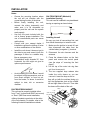
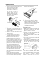
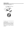
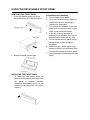
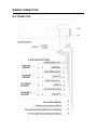
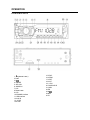
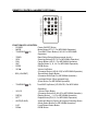
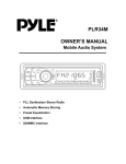
PLR44MU OWNER’S MANUAL Mobile Audio System PLL Synthesizer Stereo Radio Automatic Memory Storing Full Detachable Panel Preset Equalization USB Interface SD/MMC Interface INSTALLATION Notes: Choose the mounting location where the unit will not interfere with the normal driving function of the driver. Before finally installing the unit, connect the wiring temporarily and make sure it is all connected up properly and the unit and the system work properly. Use only the parts included with the unit to ensure proper installation. The use of unauthorized parts can cause malfunctions. Consult with your nearest dealer if installation requires the drilling of holes or other modifications of the vehicle. Install the unit where it does not get in the driver’s way and cannot injure the passenger if there is a sudden stop, like an emergency stop. If installation angel exceeds 30°from horizontal, the unit might not give its optimum performance. 30 Avoid installing the unit where it would be subject to high temperature, such as from direct sunlight, or from hot air, from the heater, or where it would be subject to dust, dirt or excessive vibration. DIN FRONT/REAR-MOUNT This unit can be properly installed either from “Front” (conventional DIN Front-mount) or “Rear” (DIN Rear-mount installation, utilizing threaded screw holes at the sides of the unit chassis). For details, refer to the following illustrated installation methods. DIN FRONT-MOUNT (Method A) Installation Opening This unit can be installed in any dashboard having an opening as shown below: 53mm 182mm Installing the unit Be sure you test all connections first, and then follow these steps to install the unit. 1. Make sure the ignition is turned off, and then disconnect the cable from the vehicle battery’s negative (-) terminal. 2. Disconnect the wire harness and the antenna. 3. Press the release button on the front panel and remove the control panel (see the steps of “removing the front panel”). 4. Lift the top of the outer trim ring then pull it out to remove it. 5. The two supplied keys release tabs inside the unit’s sleeve so you can remove it. Insert the keys as far as they will go (with the notches facing up) into the appropriate slots at the middle left and right sides of the unit. Then slide the sleeve off the back of the unit. Sleeve L Key Outer Trim Ring Front Panel R Key INSTALLATION 6. Mount the sleeve by inserting the sleeve into the opening of the dashboard and bend open the tabs located around the sleeve with a screwdriver. Not all tabs will be able to make contact, so examine which ones will be most effective. Bending open the appropriate tabs behind the dashboard to secure the sleeve in place. terminal to the dashboard. Spring Washer Hex Nut Metal Strap Mounting Bolt Plain Washer Tapping Screw Dashboard Tabs 10. Reconnect the cable to the vehicle battery’s negative (-) terminal. Then replace the outer trim ring and install the unit’s front panel (see the steps of “installing the front panel”). Screwdriver Sleeve 7. Reconnect the wire harness and the antenna and be careful not to pinch any wires or cables. 8. Slide the unit into the sleeve until it locks into place. 9. To further secure the unit, use the supplied metal strap to secure the back of the unit in place. Use the supplied hardware (Hex Nut (M5mm) and Spring Washer) to attach one end of the strap to the mounting bolt on the back of the unit. If necessary, bend the metal strap to fit your vehicle’s mounting area. Then use the supplied hardware (Tapping Screw (5x25mm) and Plain Washer) to attach the other end of metal strap to a solid metal part of the vehicle under the dashboard. This strap also helps ensure proper electrical grounding of the unit. Note to install the short threading terminal of the mounting bolt to the back of the unit and the other long threading Removing the unit 1. Make sure the ignition is turned off, then disconnect the cable from the vehicle battery’s negative (-) terminal. 2. Remove the metal strap attached the back of the unit (if attached). 3. Press the release button to remove the front panel. 4. Lift the top of the outer trim ring then pull it out to remove it. 5. Insert both of the supplied keys into the slots at the middle left and right sides of the unit, then pull the unit out of the dashboard. DIN REAR-MOUNT (Method B) If your vehicle is a Nissan, Toyota, follow these mounting instructions. Use the screw holes marked T (Toyota), N (Nissan) located on both sides of the unit to INSTALLATION fasten the unit to the factory radio mounting brackets supplied with your vehicle. Side View showing Screw Holes marked T, N Screw Factory Radio Mounting Bracket Screw Dashboard or Console To fasten the unit to the factory radio mounting brackets. Align the screw holes on the bracket with the screw holes on the unit, and then tighten the screws (5x5mm) on each side. Note: the outer trim ring, sleeve and the metal strap are not used for method B installation. USING THE DETACHABLE FRONT PANEL REMOVING THE FRONT PANEL 1. Press the release button ( ) on the front panel and pull off the front panel. 2. Keep front panel into the case. INSTALLING THE FRONT PANEL To install the front panel, insert the panel into the housing and make sure the panel is properly installed. Otherwise, abnormality occurs on the display or some keys will not function properly. Precautions when handling 1. Do not drop the front panel. 2. Do not put pressure on the display or control buttons when removing or installing the front panel. 3. Do not touch the contacts on the front panel or on the main unit body. It may result in poor electrical contact. 4. If any dirt or foreign substances adhered on the contacts, they can be removed with a clean and dry cloth. 5. Do not expose the front panel to high temperatures or direct sunlight in anywhere. 6. Keep away any volatile agents (e.g. benzene, thinner, or insecticides) from touching the surface of the front panel 7. Do not attempt to disassemble the front panel. WIRING CONNECTION ISO CONNECTION OPERATION LOCATION OF KEYS 1. (release button) 2.PWR 3.9/ 4.7/MODE 5. SEL/VOL 6. AMS/SCH 7.LOC 8.Reset button 9.LCD 10.SD/MMC interface 11.USB interface 12.AUX IN 13. 0 DSP 14.6 DIR+ 15.5 DIR16.4 RDM 17.3 RPT 18.2 INT 19. 1 PAU 20. BAND/LOUD 21. MON 22.EQ 23.8/ 24.MUT 25.IR OPERATION SWITCHING ON/OFF THE UNIT Press PWR button (2) to turn on/off the unit. FACEPLATE RELEASE Press release button (1) to detach the removable faceplate. SOUND ADJUSTMENT Press SEL button (5) shortly to select the desired adjustment mode. The adjustment mode will change in the following order: →BAS‐TRE‐BAL‐FAD‐LOUD‐EQ‐DX‐ST‐VOL BAS: bass TRE: treble BAL: balance FAD: fader LOUD: loudness EQ: equalization DX: distance ST: STEREO VOL: volume By rotating the audio knob (5) clockwise or counter-clockwise, it is possible to adjust the desired sound quality. LOUDNESS Long press the BAND button to active the LOUD function. Press it and hold again to cancel this function. MUTE Press MUTE button (24) to mute down the sound instantly. If any button is pressed in the mute state, the mute state is released. EQUALIZATION Press EQ button (22) shortly to turn on equalization function and to select desired audio mode. There are five kinds of mode as below: →FLAT→POP M→ROCK→CLAS→EQ OFF DISPLAY INFORMATION Press DISP button (9) to show the time LIQUID CRYSTAL DISPLAY Exhibit current frequency and activated functions on the display . . RESET FUNCTION RESET button (8) must be activated with either a ballpoint pen or thin metal object. The RESET button is to be activated for the following reasons: - Initial installation of the unit when all wiring is completed. - All the function buttons do not operate. - Error symbol on the display. Note: if press RESET button (8), the unit can’t work yet, please use a cotton swab soaked in isopropyl alcohol to clean the socket on the front panel. As photos : LOCAL Press LOC button (7) to select between local and distant stations. Local setting for reception of strong station, and a distant setting for reception of weaker stations. This function is effect during SEEK operation. MONO Press MON button (21) to select mono or stereo mode. You can sometimes improve reception of distant stations by selection RADIO OPERATION SWITCHING TO RADIO MODE Press MODE button (4) to select radio OPERATION mode, the radio mode appears in the display together with the memory band and frequency. SELECTING THE FREQUENCY BAND At radio mode, press BAND button (20) shortly to select the desired band. The reception band will change in the following order: →FM1→ FM2→ FM3 → MW1→ MW2 SELECTING STATION button (3) or button (23) Press shortly to activate automatic seek function. Press for several seconds until “MANUAL” appears on the display, the manual tuning mode is selected. If both buttons have not been pressed for several seconds, they will return to seek tuning mode and “AUTO” appears on the display. AUTOMATIC MEMORY STORING & PROGRAM SCANNING - Automatic memory storing Press AMS button (6) for several seconds, the radio searches from the current frequency and checks the signal strength until one cycle search is finished. And then 6 strongest stations are stored into the corresponding preset number button. - Program scanning Press AMS button (6) shortly to scan preset station. The radio is holding at that preset number for several seconds with release mute, then searches again. STATION STORING To received a station, Press one of the preset button (1~6) for 2 seconds. current station is stored into the number Button. USB PLAY OPERATION On the front panel of the unit, there is an USB interface (11). You can connect an USB driver through this interface (11). When you connect an USB driver through the interface, the unit will search the MP3 files or WMA files in the USB driver and start to play MP3 files or WMA files automatically. If in other mode, you can also press MODE button (4) to select USB mode. It supports the MP3/WMA file in the device, the operation please refer to the following instruction. SELECTING SONGS IN SINGLE STEP button (3) or button (23) to Press move to the following song or the previous song. Track number shows on display. SELECTING DIRECTORY UP/DOWN Press 5 DIR-button (15) or 6 DIR+button (14) to select previous directory or next directory. PAUSING PLAYING Press 1 PAU button (19) to pause playing. Press it again to resume playing. PREVIEWING ALL FILES Press 2 INT button (18) to INTRO each file. Shortly press again to stop intro and start to play. REPEATING PLAYING Press 3 RPT button (17) to continuously repeat the same file. Press it again to repeat all files. PLAYING IN RANDOM ORDER Shortly press 4 RDM button (16) to play all files in random order. Press it again to cancel the function. SD/MMC OPERATION There is a SD/MMC interface (10) on the front panel of the unit. When you insert a SD/MMC card in the OPERATION SD/MMC interface, the unit will search the MP3 files or WMA files in the card and start to play automatically. The operation is the same with the USB play operation described above. If in other mode, you can also press MODE button (4) to select SD/MMC mode. CAUTION: When there are important files in the USB Device or SD card, do not connect it to the main unit to play, because any wrong operation may cause files loss. And our company assumes no responsibility for this. REMOTE CONTROL HANDSET(OPTIONAL) FUNCTION KEY & CONTROL - POWER Power ON/OFF Button - MODE Mode Botton(S,T,U,7,For MP3/WMA Operation) - TUNE/SKIP (8) Tune/SKIP Down Button(V,W,X,8 For MP3/WMA Operation) - 7/BND Band Select Button(When pressed shortly) - SCN Scanning Button(D,E,F,2 For MP3/WMA Operation) - PAU Pause Button (A,B,C,1 For MP3/WMA Operation) - SHF Shuffle Button (J, K, L 4 For MP3/WMA Operation) - DIR▼ DIR▼ Button - VOL▲ Volume Up Button (Character Select (A,B~8,9,0)For MP3/WMA Operation) - SEL (LOU/ENT) Sound Mode Select Button (Character Shift Right For MP3/WMA Operation) Loudness Button (When pressed long) (Enter Button For MP3/WMA Operation) - TUNE/SKIP - VOL ▼ - DSP(0) RPT AS/PS(D-AUD) - LOC DIR▲ (9) Tune/SKIP Up Button(Y,Z,SPACE,9 For MP3/WMA Operation) Volume Down Button (Character Select(A,B~8,9,0)For MP3/WMA Operation) Display Button(_,-,+,0 For MP3/WMA Operation) Repeat Button(G,H,I,3 For MP3/WMA Operation) Automatic Memory Storing & Program Scanning Button (Mode Select Button For MP3/WMA Operation) Local/Distant Select Button DIR▼ Button SPECIFICATION GENERAL Power Supply Requirements Chassis Dimensions Tone Controls - Bass (at 100 Hz) - Treble (at 10 kHz) Maximum Output Power - Version V Current Drain - Version V - Power Version) RADIO Frequency Coverage IF Sensitivity (S/N=30dB) Stereo Separation : DC 12 Volts, Negative Ground : 178 (W) x 107 (D) x 50 (H) : ±10 dB : ±10 dB : 4x60 watts :5 Ampere (max.) For 2 Bands (Europe) FM 87.5 to 108 MHz 10.7 MHz 4μV >25dB AW Frequency Coverage 520 to 1710 kHz IF 450 kHz Sensitivity (S/N=20dB) 36 dBu TROUBLE SHOOTING Before going through the checklist, check wiring connection. If any of the problems persist after checklist has been made, consult your nearest service dealer. Symptom No power Cause The car ignition switch is not on The fuse is blown. No sound BRAND CAR STEREOS Volume is in minimum Solution If the power supply is connected to the car accessory circuits, but the engine is not moving, switch the ignition key to “ACC” Replace the fuse Adjust volume to a desired level Wiring is not properly connected Check wiring connection The operation keys do not work The built-in microcomputer is not operating properly due to noise Press the reset button The radio does not work. The radio station automatic selection does not work The antenna cable is not connected Insert the antenna cable firmly The signals are too weak Select a station manually CAR AUDIO SYSTEMS