1
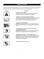
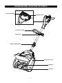
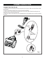
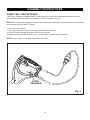
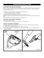
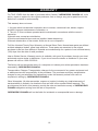
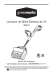
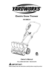
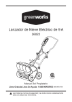
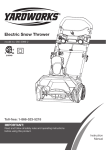
8 A Electric Snow Thrower
060-3984-0
Owner’s Manual
TOLL-FREE HELPLINE: 1 866 523-5218
IMPORTANT:
Read all safety rules and instructions carefully before operating this tool.
TABLE OF CONTENTS
SPECIFICATIONS...........................................................................................................................2
SAFETY RULES...............................................................................................................................3
DIAGRAM AND LOCATION OF PARTS..........................................................................................8
ASSEMBLY INSTRUCTIONS...........................................................................................................9
OPERATING INSTRUCTIONS.......................................................................................................11
MAINTENANCE..............................................................................................................................12
TROUBLESHOOTING...................................................................................................................17
WARRANTY...................................................................................................................................18
EXPLODED VIEW..........................................................................................................................19
PARTS LIST...................................................................................................................................20
SPECIFICATIONS
Motor.......................................................................................................................120 V, 60 Hz, 8 A
Blade speed............................................................................................................ Up to 2,600 RPM
Clearing width...................................................................................................................12˝ (30 cm)
Clearing depth................................................................................................................ 4˝ (10.2 cm)
Blade width....................................................................................................................10˝ (25.4 cm)
Discharge distance.......................................................................................................Up to 20' (6 m)
Weight............................................................................................................................14 lb (6.3 kg)
2
SAFETY RULES
Read this entire Owner's Manual carefully and understand it thoroughly before attempting to
assemble or operate this Snow Thrower. These safety rules are not meant to cover every possible
condition that may occur. If questions arise concerning the product, contact the Toll-Free Helpline,
at 1-866-523-5218, between 8:30 a.m. and 5:00 p.m. EST, Monday to Friday.
Safety Signals
The purpose of safety signal statements and symbols is to indicate possible danger. Read these
statements carefully in order to understand and practice proper accident prevention.
DANGER
Indicates an EXTREME hazard.
Failure to obey a DANGER safety signal will result in serious injury or death to the operator or to
others. Always follow the safety precautions in order to reduce the risk of fire, electric shock, and
personal injury.
WARNING Indicates a serious hazard.
Failure to obey a WARNING safety signal may result in serious injury to the operator or to others.
Always follow the safety precautions in order to reduce the risk of fire, electric shock, and personal
injury.
CAUTION Indicates a moderate hazard.
Failure to obey a CAUTION safety signal may result in property damage or personal injury to the
operator or to others. Always follow the safety precautions in order to reduce the risk of fire,
electric shock, and personal injury.
IMPORTANT! Indicates special mechanical information.
NOTE: Indicates additional important information that is general in nature.
Safety Symbols
IMPORTANT! Some of the following symbols may appear on the Snow Thrower. Study them
carefully and learn their meaning.
Proper interpretation of these symbols will allow for more efficient and safer operation of the Snow
Thrower.
SYMBOL
NAME
EXPLANATION
V
A
Hz
n0
.../min
Volt
Amperes
Hertz
No load speed
Movements per minute
~
Alternating current
Direct current
Class II
Potential voltage
Current
Frequency (cycl s per second)
Rotational speed at no load
Revolutions, strokes, surface per minute speed, orbits,
etc. per minute
Type or a characteristic of current
Type or a characteristic of current
Designates double insulation
---
3
SAFETY RULES
Double insulated Snow Thrower
DANGER: Basic safety precautions should always be followed when using electric tools
in order to reduce the risk of fire, electric shock, and personal injury. Read the entire
Owner's Manual carefully and understand it thoroughly before using this Snow Thrower.
Pay close attention to the operating instructions and safety rules.
• This Snow Thrower is “DOUBLE INSULATED”
Extension Cord
WARNING: In order to reduce the risk of electric shock when operating this Snow
Thrower, use only a CSA-listed extension cord that is approved for outdoor use, such as
Type SJTW, 16AWG, and that has a lower temperature rating of -40° F (-40° C).
• Ground Fault Circuit Interrupter (GFCI) protection should be provided on the circuit(s) or outlet(s)
that will be used for this Snow Thrower. For an extra measure of safety, use a receptacle that has
built-in GFCI protection.
• The nameplate on the Snow Thrower indicates the voltage used. Do not connect the Snow
Thrower to an AC circuit that provides a different voltage from the voltage that is indicated on the
nameplate.
Recommended size of extension cords
Amperage rating of the tool
(120 V circuit only)
More than
6
Not more than
10
Total length of the extension cord
25’ (7.6 m)
50’ (15.2 m)
100’ (30.4 m)
150’ (45.7 m)
Minimum Gauge for the extension cord (AWG)
18
16
14
12
WARNING: In order to prevent electric shock, use an extension cord that is suitable for
outdoor use.
• Inspect the extension cord and the power cord on a regular basis. Look for deterioration, cuts, or
cracks in the insulation. Inspect the connections for damage. Repair or replace the extension cord
or the power cord if any damage is found.
• Verify that the rotor and all moving parts have come to a complete stop, and disconnect the
Snow Thrower from the power supply in order to prevent accidental start-ups before cleaning or
performing any inspections or repairs.
• Do not abuse the extension cord. Do not carry the Snow Thrower by the power cord or pull on
the cord in order to disconnect it from the receptacle.
• Keep the extension cord away from heat, oil, and sharp edges in order to prevent damage.
• If the extension cord is damaged in any manner while it is plugged in, disconnect it from the
outlet immediately.
• Prevent any possible disconnection of the power cord from the extension cord while the Snow
Thrower is in use by using the cord retainer and guide bar. Refer to the section entitled Using the
Cord Retainer.
4
SAFETY RULES
• Avoid accidental start-ups. Do not carry the Snow Thrower with a finger on the switch while it is
plugged in. Verify that the switch is in the "OFF" position before plugging in the Snow Thrower.
• Unplug the Snow Thrower and allow it to cool down before putting it into storage. Store the Snow
Thrower indoors.
• Unplug the Snow Thrower when it is not in use and before performing any maintenance or repairs.
FOLLOW THESE RULES WHILE OPERATING THE SNOW THROWER
• Walk. Do not run.
• Verify that the Snow Thrower is not in contact with anything before turning it on.
• Stay away from the discharge opening at all times. Keep face, hands, and feet away from
concealed, moving, or rotating parts.
• Be attentive when using the Snow Thrower, and stay alert for holes in the terrain and other
hidden hazards or traffic.
• Do not use the Snow Thrower on a gravel or crushed rock surface. Use extreme caution when
crossing gravel/crushed rock drives, walks, or roads.
• Move up and down slopes when clearing snow. Do not go across a slope. Use caution when
changing direction. Do not use this Snow Thrower to clear snow from steep slopes.
• Do not attempt to use the Snow Thrower on a roof or on any steeply inclined slippery surface.
• Do not operate the Snow Thrower if the guards, plates, and other safety protective devices are
not in place.
• Do not operate the Snow Thrower near glass enclosures, automobiles, trucks, window wells,
drop-offs, etc. without properly adjusting the angle of the snow discharge. Keep children and pets
away from the work area.
• Do not force or overload the Snow Thrower. The Snow Thrower will perform better and safer
when it is used at the rate that it was designed to work at.
• Do not operate the Snow Thrower at high speeds on slippery surfaces. Look behind, and
exercise caution when backing up.
• Do not direct the discharge toward people, and do not allow anyone to move in front of the Snow
Thrower while it is in use.
• Wear safety glasses or goggles that meet ANSI Z87.1 standards, and wear ear/hearing
protection when using this Snow Thrower.
• Use the Snow Thrower in daylight or in good artificial light.
• Avoid accidental start-ups. Remain in the starting position when turning the Snow Thrower on.
The operator and the Snow Thrower must be in a stable position during start-up. See the section
entitled Starting/Stopping Instructions.
• Use the proper tool. Only use this Snow Thrower for the purpose that it was designed for.
• Do not overreach. Always keep proper footing and balance.
• Hold the Snow Thrower with both hands while it is in use. Keep a firm grip on the handles or the
grips.
• Keep hands, face, and feet away from all moving parts. Do not touch or try to stop the impeller
while it is rotating.
• If the impeller does not rotate freely due to frozen ice, thaw the Snow Thrower thoroughly before
attempting to use it.
• Keep the impeller clear of debris.
• Do not attempt to clear the impeller while the motor is running or while the Snow Thrower is
plugged in it. Turn the motor off and unplug the Snow Thrower from the extension cord or the
outlet.
5
SAFETY RULES
• Keep clothing and body parts away from the rotor.
• Do not operate the motor at a faster speed than necessary. Do not run the motor at high speed
while not clearing snow.
• Stop the motor when snow clearing is delayed or when moving from one location to another.
• Unplug the Snow Thrower when it is being transported and when it is not in use.
• After striking a foreign object, turn the Snow Thrower off and unplug it, and then inspect it for
damage. Repair any damage before restarting and using the Snow Thrower.
• If the Snow Thrower starts to vibrate abnormally, stop the Snow Thrower immediately and attempt
to determine the cause. Vibration is generally an indication of danger.
• Stop the motor and unplug the Snow Thrower whenever the operator is not in the operating
position, before unclogging the impeller, and before making any repairs, adjustments, or inspections.
• Do not discharge snow onto public roads or near moving traffic.
• Allow the Snow Thrower to run for a few minutes after clearing snow in order to prevent moving
parts from freezing.
• Use only the manufacturer's original replacement parts and accessories for this Snow Thrower.
The use of unauthorized parts or accessories could lead to serious injury to the user or damage
the Snow Thrower, and will void the warranty.
• Do not use the Snow Thrower in the hand held position. Do not pick up the Snow Thrower while it
is plugged and running. The Snow Thrower is designed to travel along the ground.
GENERAL SAFETY RULES
• Verify that the Snow Thrower is secure while transporting.
• Store the Snow Thrower in a dry area, locked up or high enough to prevent unauthorized use or
damage, and out of the reach of children.
• Do not douse or squirt the unit with water or any other liquid. Keep handles dry, clean, and free of
debris. Clean the Snow Thrower after each use. See the section entitled Cleaning and Storage.
• If the labels on the Snow Thrower become defaced or start to lift off, contact the Toll-Free
Helpline, at 1 866 523-5218.
• Keep these instructions in a safe place for future reference. Refer to them often, and use them to
instruct other users. Anyone who uses this Snow Thrower must read these instructions carefully.
• Maintain the Snow Thrower with care. Follow the instructions for lubricating and changing
accessories.
6
SAFETY RULES
This Owner's Manual describes safety and international symbols and pictographs that may appear
on this product. Read this Owner's Manual carefully for complete information concerning safety,
assembly instructions, operating instructions, and maintenance and repairs.
SYMBOL
MEANING
• SAFETY ALERT SYMBOL
Indicates danger, warning, or caution. May be used in
conjunction with other symbols or pictographs.
• WARNING - READ THE OWNER'S MANUAL
Read the Owner's Manual carefully and follow all warnings
and safety instructions. Failure to do so may result in
serious injury to the operator and/or bystanders.
• KEEP BYSTANDERS AWAY
WARNING: Keep all bystanders, and especially children
and pets, at least 50 feet (15 m) away from the operating
area.
• THROWN OBJECTS AND ROTATING CUTTER MAY
CAUSE SEVERE INJURY
WARNING: Small objects can be propelled at high speed,
causing injury. Keep away from the rotating rotor.
• SPINNING ROTOR MAY CAUSE SEVERE INJURY
WARNING: Keep hands, feet, and clothing away from the
discharge area. Do not step in front of the Snow Thrower,
and do not use hands to clean the rotor area while the
Snow Thrower is plugged in.
• KEEP HANDS AND FEET AWAY
7
DIAGRAM AND LOCATION OF PARTS
Lock-out button
Trigger switch
Auxiliary handle
Lock knob
Height adjustment
Belt drive cover
Impeller
Scraper
8
ASSEMBLY INSTRUCTIONS
CONNECTING THE POLES
1. Carefully remove the product and any accessories from the box. Make sure that all items listed
are included.
2. Remove packaging material from cord and discard immediately.
3. Align the slot on the handle pole and the button on the lower pole. Slide the handle pole into
lower pole until you hear the button click.
4. Raise the collar on the lower pole to the threaded base on the handle pole and rotate clockwise
to secure.
SLOT
BUTTON
COLLAR
Fig. 1
9
ASSEMBLY INSTRUCTIONS
USING THE CORD RETAINER
This Snow Thrower is equipped with a cord retainer in order to prevent the extension cord from
disconnecting from the power cord while the Snow Thrower is in use.
NOTE: Do not plug the extension cord into the outlet until it has been connected to the cord retainer
and plugged into the Snow Thrower.
To use the cord retainer:
1. Fold the extension cord to form a tight loop near the retainer.
2. Push the loop through the bottom hole in the retainer.
3. Slide the loop over the retaining clip, and pull down until the cord is secured.
NOTE: Use a CSA or CuL-approved extension cord.
CORD
RETAINER
Fig. 2
10
OPERATING INSTRUCTIONS
STARTING THE SNOW THROWER
Avoid accidental start-ups. Verify that the operator is in the starting position when using the snow
thrower. In order to avoid serious injury, the operator and unit must be in a stable position when
starting the Snow Thrower.
Follow this sequence exactly in order to start the Snow Thrower.
1. Verify that the Snow Thrower is plugged in.
2. Press and hold the lock-out button (Fig. 3).
3. While holding the lock-out button, press and hold the trigger switch.
NOTE: The Snow Thrower will not start if the lock-out button is not held until the trigger switch is
lifted.
4. Hold the handles and begin to use the Snow Thrower (Fig. 4).
STOPPING THE SNOW THROWER
1. Release the trigger switch.
2. The lock-out button will pop out, and the Snow Thrower will stop.
USING THE SNOW THROWER
1. Start the Snow Thrower by following the Starting instructions. The depth and weight of the
snow will determine the forward speed.
2. Push the Snow Thrower forward so that it rides on the scraper.
3. Verify that the power cord is attached to the cord retainer. The power cord should trail to the
side of the operator.
Trigger
Switch
Lock-Out
Button
Fig. 3
Fig. 4
11
MAINTENANCE
SERVICING
Servicing should be performed by a qualified technician. Replacement parts for this Snow
Thrower must be identical to the parts that they replace. If repairs are necessary, contact the
Toll-Free Helpline, at 1-866-523-5218.
INSPECTING/REPLACING THE DRIVE BELT
When servicing the Snow Thrower, use only the manufacturer's original replacement parts.
Inspect the drive belt for wear once per year or every 50 hours of operation, whichever comes
first. If the drive belt needs to be replaced, follow these steps.
In order to avoid serious personal injury, turn off the Snow Thrower and allow it to cool down.
Unplug the Snow Thrower before performing any maintenance.
1. Remove the ten (10) screws from the belt cover using a phillips screwdriver (Fig. 5). Remove 3
screws for the impellar bracket shown in (Fig. 6).
In order to reduce the risk of electric shock, replace the cover before connecting the Snow
Thrower to a power source.
2. Pull the belt tensioner (idler arm) away from the drive pulley. Remove the damaged or broken
belt from the impeller pulley and the drive pulley inside the housing. Discard the belt in the proper
manner (Fig. 6).
3. Loop the new belt around the drive pulley and the impeller pulley (Fig. 6). Pull the belt tensioner
(idler arm) away from the drive pulley in order to install the belt around the drive pulley.
NOTE: Verify that the washer is still in place on the impeller pulley shaft before reinstalling the
belt cover.
4. Reinstall the belt cover with the ten (10) screws. Reinstall the impellar pulley bracket three
screws. In order to facilitate the installation, position the narrow part of the cover into the recess of
the housing and install the two top screws and then push the rest of the cover down into recess
and over the rotor shaft. Tighten all ten (10) screws.
Fig. 5
Fig. 6
WARNING: When fitting the belt back into the main housing, verify that the belt is
positioned to the right of the Drive Belt Retainer. If the belt is positioned to the left of the
Drive Belt Retainer, serious damage may occur.
12
MAINTENANCE
REPLACING THE SCRAPER
WARNING: In order to avoid serious personal injury, turn the Snow Thrower off and
unplug it before performing any maintenance.
Use only the manufacturer's original replacement parts.
1. Place the Snow Thrower on the ground or on a work bench. Position the Snow Thrower so that
the impeller is facing up.
2. Remove the three (3) screws that are located beneath the impeller that secure the scraper to
the housing using a phillips screwdriver. (Fig. 7).
3. Remove the scraper, and discard it in the proper manner.
4. Snap the new scraper into position, and attach it to the Snow Thrower by reinstalling the three
(3) screws.
Fig. 7
13
MAINTENANCE
IMPELLOR REPLACEMENT
1
2
3
spring
1. Remove the nut from the
left hand side of the impellor
shaft.
4
2. Remove the 10 screws
from the side cover.
5
3. Be sure not to lose the 2
springs.
6
spacer washer
4. Remove the nut from the
impellor shaft.
7
5. Remove the 3 screws
holding the pulley support
plate.
8
7. Remove the pulley and
belt.
10
6. Remove the plate and the
two spacer washers.
9
8. Remove the impellor shaft
nut from the right hand side.
11
9. Withdraw the impellor shaft
from the left hand side.
12
spacer washer
10. Withdraw the old /
damaged impellor. Be sure to
keep the 2 spacer washers
from the right hand side of the
impellor.
11. Insert the impellor shaft in
the new impellor and place
the 2 washers on the right
hand side.
14
12. Place the impellor and
shaft back into the front
scoop.
MAINTENANCE
13
13. Place the pulley back onto
the impellor shaft.
16
14
15
14. Be sure to route the belt
correctly, as shown.
17
15. Replace the 2 spacer
washers on the impellor shaft.
18
spring
impellor shaft
washer and nut
16. Replace the pulley
support plate and the 3
retaining screws.
19
17. Replace and tighten the
impellor shaft washer and nut.
20
18. Place the upper spring
into position and then finger
tighten the cover plate into
place as shown.
21
spring
19. Place the lower spring into
position and slide the side
cover up using slight pressure
to hold the spring in place.
20. Replace and tighten the
remaining screws and the nut
and washer.
15
21. Re-install the impellor
shaft nut and washer on the
right hand side, and tighten.
MAINTENANCE
STORAGE
• Allow the motor to cool down before storing.
• Store the Snow Thrower in a locked location in order to prevent unauthorized use or damage.
• Store the Snow Thrower in a dry, well-ventilated area.
• Store the Snow Thrower out of the reach of children.
CLEANING
In order to avoid serious personal injury, turn the Snow Thrower off and unplug it before cleaning
or servicing.
Use a small brush to clean the outside of the Snow Thrower. Do not use strong detergents.
Household cleaners that contain aromatic oils such as pine and lemon, and solvents such as
kerosene can damage the plastic housing and handles. Wipe off any moisture using a soft cloth.
TRANSPORTING THE SNOW THROWER
• Allow the motor to cool down before transporting.
• Secure the Snow Thrower while transporting.
• When moving the Snow Thrower, grasp it by the top and auxiliary handles (Fig. 8).
• When transporting the Snow Thrower with the handles folded, be careful not to make contact
with the discharge directional control and accidentally bend it. If the control is bent or damaged, it
will not be possible to adjust the vanes.
Fig. 8
16
TROUBLESHOOTING
THE SNOW THROWER DOES NOT START
CAUSE
The Snow Thrower is unplugged.
The lock-out button or trigger switch were
not used properly.
The overload protection switch has popped
out.
SOLUTION
Verify that the Snow Thrower is plugged into an
electrical outlet.
Press and hold the lock-out button, and then lift
and hold the trigger switch (see the section
entitled Starting the Snow Thrower).
See the section entitled Overload Protection
Switch.
THE MOTOR IS ON, BUT THE ROTOR DOES NOT TURN
CAUSE
The belt is damaged.
SOLUTION
Replace the belt (see the section entitled
Inspecting/Replacing the Drive Belt).
THE SNOW THROWER LEAVES A THIN LAYER OF SNOW BEHIND
CAUSE
The scraper is worn.
SOLUTION
Replace the scraper (see the section entitled
Replacing the Scraper).
If further assistance is required, contact the Toll-Free Helpline, at 1-866-523-5218.
17
WARRANTY
For TWO YEARS from the date of purchase within Canada, YARDWORKS CANADA will, at its
option, repair or replace for the original purchaser, free or charge, any part or parts found to be
defective in material or workmanship.
This warranty does not cover:
1. Any part which has become inoperative due to misuse, commercial use, abuse, neglect,
accident, improper maintenance or alteration; or
2. The unit, if it has not been operated and/or maintained in accordance with the owner's
manual;or
3.Normal wear, except as noted below;
4.Routine maintenance items such as impeller, blade sharpening;
5.Normal deterioration of the exterior finish due to use or exposure.
Full One Hundred Twenty Days Warranty on Normal Wear Parts: Normal wear parts are defined
as blade adaptors, blades, grass bags and tires. These parts are warranted to the original
purchaser to be free from defects in material and workmanship for a period of one hundred twenty
(120) days from the date of retail purchase.
How to Obtain Service: Warranty service is available, with proof of purchase, through your local
authorized service dealer or distributor. If you do not know the dealer or distributor in your area,
please call toll free 1 866 523-5218.
The factory will not accept the return of a complete unit unless prior written permission has been
extended by YARDWORKS CANADA.
Transportation Charges: Transportation charges for the movement of any power equipment unit
or attachment are the responsibility of the purchaser. The purchaser must pay transportation
charges for any part submitted for replacement under this warranty unless such return is
requested in writing by YARDWORKS CANADA.
Other Warranties: All other warranties, express or implied, including any implied warranty of
merchantability is limited in its duration to that set forth in this express limited warranty. The
provisions as set forth in this warranty provide the sole and exclusive remedy of YARDWORKS
CANADA obligations arising from the sale of its products.
YARDWORKS CANADA will not be liable for incidental or consequential loss or damage.
18
EXPLODED VIEW
19
PARTS LIST
ITEM NO.
1
2
3
4
5
6
7
8
9
10
11
12
13
14
15
16
17
18
19
20
21
22
23
24
25
26
27
28
29
30
31
32
33
34
35
36
37
38
39
40
41
42
43
44
45
MODEL NO.
36401263
3420101-1
3220905
3410302
36301263
34106263
34107263
34203625
34101185-2
34105185-3
3290205
31101627
3640198-3
34201625
34202625
3410801
3410898-4
3330198
3111198
3390298
3220298
3330298
3220998
3290499
3290198
3220236
3330198
3220898
3220598
3111298A
3320198
31105627
32206302A
3290173
3412098A
3225599
32261198
3411298
3411798
31102627
3330498
3220475
3410998-4
31103627
31104627
DESCRIPTION
Pigtail cable
Cord guard
Screw
Wire clip
Switch assembly
Left upper handle
Right upper handle
Protect pacer
Knob
Auxiliary handle
Nut M6
Tube assembly
Cord
Rubber sealing ring
Protect pacer
Wire clip
Front housing
Spring
Tension wheel assembly
Spring
Screw
Left cover
Cover nut
Washer
Belt
Nut M10
Impeller pulley bracket
Washer
Screw
Impeller pulley assembly
Impellor shaft
Impellor assembly
Screw
Washer
Snow spade
Screw
Washer
Lower housing
Right cover
Motor assembly
Motor mounting bar
Screw
Rear housing
Right grill assembly
Left grill assembly
20
QTY
1
1
2
2
1
1
1
1
1
1
1
1
2
1
1
1
1
1
1
1
38
1
1
2
1
1
1
3
3
1
1
1
2
2
1
33
1
1
1
1
1
2
1
1
1