1
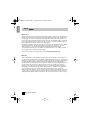
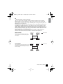
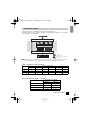
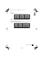
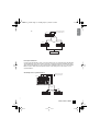
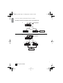
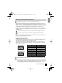
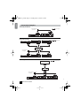
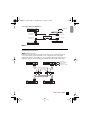
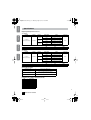
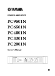
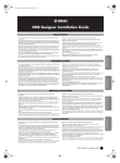
INTERFACE CARD
MY16-C
Owner’s Manual
FCC INFORMATION (U.S.A.)
1. IMPORTANT NOTICE: DO NOT MODIFY THIS
UNIT!
This product, when installed as indicated in the
instructions contained in this manual, meets FCC
requirements. Modifications not expressly
approved by Yamaha may void your authority,
granted by the FCC, to use the product.
2. IMPORTANT: When connecting this product to
accessories and/or another product use only high
quality shielded cables. Cable/s supplied with this
product MUST be used. Follow all installation
instructions. Failure to follow instructions could void
your FCC authorization to use this product in the
USA.
3. NOTE: This product has been tested and found to
comply with the requirements listed in FCC Regulations, Part 15 for Class “B” digital devices. Compliance with these requirements provides a
reasonable level of assurance that your use of this
product in a residential environment will not result
in harmful interference with other electronic
devices. This equipment generates/uses radio frequencies and, if not installed and used according
to the instructions found in the users manual, may
cause interference harmful to the operation of
other electronic devices. Compliance with FCC
regulations does not guarantee that interference
will not occur in all installations. If this product is
found to be the source of interference, which can
be determined by turning the unit “OFF” and “ON”,
please try to eliminate the problem by using one of
the following measures:
Relocate either this product or the device that is
being affected by the interference.
Utilize power outlets that are on different branch
(circuit breaker or fuse) circuits or install AC line filter/s.
In the case of radio or TV interference, relocate/
reorient the antenna. If the antenna lead-in is 300
ohm ribbon lead, change the lead-in to co-axial
type cable.
If these corrective measures do not produce satisfactory results, please contact the local retailer
authorized to distribute this type of product. If you
can not locate the appropriate retailer, please contact Yamaha Corporation of America, Electronic
Service Division, 6600 Orangethorpe Ave, Buena
Park, CA90620
The above statements apply ONLY to those products distributed by Yamaha Corporation of America or its
subsidiaries.
* This applies only to products distributed by YAMAHA CORPORATION OF AMERICA.
(class B)
This device complies with Part 15 of the FCC Rules. Operation is subject to the following two conditions:
(1) this device may not cause harmful interference, and (2) this device must accept any interference
received, including interference that may cause undesired operation.
This Class B digital apparatus complies with Canadian ICES-003.
Cet appareil numérique de la classe B est conforme à la norme NMB-003 du Canada.
MY16-C_E.book Page 2 Tuesday, April 13, 2004 7:32 PM
ENGLISH
PRECAUTIONS
PLEASE READ CAREFULLY BEFORE PROCEEDING
* Please keep this manual in a safe place for future reference.
WARNING
Always follow the basic precautions listed below to avoid the possibility of serious injury or even death
from electrical shock, short-circuiting, damages, fire or other hazards. These precautions include, but are
not limited to, the following:
• Before installing the MY16-C in an audio device please check to make sure that the device is compatible with the MY16-C, and
check possible restrictions regarding the maximum number of Yamaha and third-party expansion cards that can be
simultaneously installed. Refer to the operation manual supplied with the audio device, and/or the Yamaha Pro Audio web site
at: http://www.yamahaproaudio.com/
• Do not install the MY16-C card in any Yamaha products not specified by Yamaha for use with the MY16-C to avoid possible
electrical shock, fire, or equipment damage.
• Do not attempt to disassemble or modify the card. Do not apply excessive force to card connectors or other card components.
Mishandling of the card may lead to shock, fire hazard, or equipment failure.
• Be sure to disconnect the power cable of the main unit before installing this card (in order to eliminate shock hazard).
• Turn off all peripheral devices connected to the host device before installation, and unplug all related cables.
CAUTION
Always follow the basic precautions listed below to avoid the possibility of physical injury to you or others,
or damage to the device or other property. These precautions include, but are not limited to, the following:
• Do not touch the metallic leads (pins) of the circuit board when handling the card. The pins are sharp and may cause hand cuts.
• Wear a pair of heavy gloves during installation to avoid scratching or cutting your hands on sharp edges.
• Avoid touching exposed connectors and metal parts to minimize the possibility of bad connections.
• Drain all static electricity from your clothing and body before handling the card. Static electricity can damage the card. Touch an
exposed metal part of the host device or other grounded object beforehand.
• Do not drop the card or subject it to physical shock as this can result in breakage and/or malfunction.
• Do not drop screws or other small parts inside the card. If power is applied while screws or similar metal objects are loose
inside the unit the card may malfunction or be damaged. If you cannot retrieve dropped objects yourself, refer the problem to
qualified Yamaha service personnel.
C2
Yamaha cannot be held responsible for damage caused by improper use or modifications to the device, or data that is lost or destroyed.
2
MY16-C Owner’s Manual
ENGLISH
table of contents.fm Page 3 Wednesday, April 14, 2004 5:39 PM
Table of contents
About CobraNet™ . . . . . . . . . . . . . . . . . . . . . . . . . . . . . . . . . . . . . . . . . . . . . . . . . . . 4
The MY16-C System . . . . . . . . . . . . . . . . . . . . . . . . . . . . . . . . . . . . . . . . . . . . . . . . . 7
Controls & Functions . . . . . . . . . . . . . . . . . . . . . . . . . . . . . . . . . . . . . . . . . . . . . . . . 8
Clock Synchronization Modes . . . . . . . . . . . . . . . . . . . . . . . . . . . . . . . . . . . . . . . . 12
MY16-C Card Installation Procedure . . . . . . . . . . . . . . . . . . . . . . . . . . . . . . . . . . . 15
Connection Examples . . . . . . . . . . . . . . . . . . . . . . . . . . . . . . . . . . . . . . . . . . . . . . 16
Specifications . . . . . . . . . . . . . . . . . . . . . . . . . . . . . . . . . . . . . . . . . . . . . . . . . . . . . 18
Greetings
Thank you for choosing the Yamaha MY16-C CobraNet™ INTERFACE CARD.
The MY16-C is a CobraNet™* expansion card for use with compatible Yamaha professional audio
equipment. Complying to CobraNet™ standards, the MY16-C allows transmission and reception of
up to 32 channels (16 in/16 out) of uncompressed digital audio data.
* CobraNet™: An audio networking system developed by Peak Audio (a division of Cirrus Logic,
Inc.) that allows real-time transmission and reception of multiple channels of uncompressed digital
audio signals via a Fast Ethernet (100 megabits/sec.) network. A single network cable can handle
a maximum of 64 channels (128 channels bidirectional) of audio data.
The Peak Audio home page can be viewed on the web at: http://www.peakaudio.com/
In order to take full advantage of the advanced features and performance provided by the MY16-C
card we urge you to read this manual thoroughly, and keep it in a safe place for further reference.
Before installing the MY16-C in an audio device please check to make sure that the device is
compatible with the MY16-C, and check possible restrictions regarding the maximum number of
Yamaha and third-party expansion cards that can be simultaneously installed.
The Yamaha Pro Audio web site is at: http://www.yamahaproaudio.com/
Package Contents
• MY16-C card
• This manual
The illustrations in this document are for instructional purposes, and may appear somewhat different from the actual equipment.
CobraNet and Peak Audio are trademarks of Cirrus Logic, Inc.
Ethernet is a trademark of Xerox Corporation.
All other trademarks are the property of their respective holders and are hereby acknowledged.
1
MY16-C Owner’s Manual
3
MY16-C_E.book Page 4 Tuesday, April 13, 2004 7:32 PM
ENGLISH
About
■ CobraNet is …
An audio networking system developed by Peak Audio (a division of Cirrus Logic, Inc.) that allows
real-time transmission and reception of uncompressed digital audio signals via a Fast Ethernet
network cable. The network can simultaneously handle up to 64 input and output channels, for a
total of 128 channels (64 channels if repeater hubs are used). The maximum number of channels
than can be handled in practical situations may be lower due to performance limitations imposed
by the equipment used and the condition of the audio signal.
Currently, the CobraNet network will handle 16, 20, or 24-bit audio at sampling rates of 48 or 96 kHz.
The CobraNet network is capable of transmitting control data at the same time as the audio
signals. The types of control data transmitted are determined by the equipment used.
The CobraNet network imposes a 5.33-millisecond (2.67 milliseconds or 1.33 milliseconds with
some settings) latency on transferred audio signals.
Refer to the Peak Audio home page for more details: http://www.peakaudio.com/
■ Bundles
2
Audio is transmitted over the CobraNet network in units known as “bundles.” These bundles are
processed at the receiving end to reconstitute the original audio signals. In the case of the MY16-C
a bundle can contain from 3 to 8 channels. Each bundle is identified by a number from 0 to 65,279,
and audio transmission via the network becomes possible when the same bundle number is
specified at both the transmitting and receiving devices. Bundles can be transmitted and received
over the entire network as long as sufficient network resources are available. The system is
designed so that each device can transmit and receive up to 8 bundles simultaneously, but the
actual number of bundles that can be handled will depend on the capabilities of the equipment
used. The MY16-C can be set to handle 2 transmit bundle numbers and 2 receive bundle
numbers. The bundle numbers can be specified via the rotary switches on the MY16-C card itself,
or via the device or software used by the device in which the card is installed. The procedure for
setting the MY16-C bundle numbers is described in the "Controls & Functions" section on page 8.
4
MY16-C Owner’s Manual
■ Multicast Bundles and Unicast Bundles
Two types of bundle can be used with CobraNet: “multicast” bundles and "unicast" bundles.
Multicast bundles can be transmitted from a single device to all devices on the network, while
unicast bundles are transferred from a single transmitting device to a single receiving device or a
limited number of receiving devices.
Unicast bundles are only sent to devices which have been set to the same bundle number as the
transmitting device. Multicast bundles are sent to all devices on the network regardless of their
settings, but only bundles with the specified bundle number(s) are processed. For this reason
multicast bundles make heavy use of network resources and it is recommended that the maximum
number of bundles be limited to 4 (32 channels). Unicast bundles should be employed when it is
necessary to handle 5 or more bundles at a time.
Different number ranges are used for multicast and unicast bundles: multicast bundles are
numbered 1 through 255, while unicast bundles are numbered 256 through 65,279.
Multicast Bundles
Multicast bundles transmitted from device A are
sent to all devices on the network (B through D in
the example).
CobraNet Device
CobraNet Device
Digital Audio Data
D
C
Network
B
Unicast Bundles
Unicast bundles are received only by devices set to
receive the same bundle numbers as the transmit
bundle number of the transmitting device A (device
D in this example).
A
CobraNet Device
CobraNet Device
CobraNet Device
CobraNet Device
Digital Audio Data
D
C
Network
B
CobraNet Device
A
CobraNet Device
3
MY16-C Owner’s Manual
5
ENGLISH
MY16-C_E.book Page 5 Tuesday, April 13, 2004 7:32 PM
MY16-C_E.book Page 6 Tuesday, April 13, 2004 7:32 PM
n Digital signals and control data are transmitted and received by all conductor and performer
devices on the CobraNet network.
Performer (Receive)
Performer (Receive)
Sync (Word Clock)
D
C
Network
Conductors transmit the synchronization
signal that is received and used by
performers. Clock synchronization is
necessary to transfer digital audio data to
and from devices outside the CobraNet
network. In this example device B on the
CobraNet network sends the synchronization
signal to external device E.
B
A
Performer
(Receive)
Conductor
(Transmit)
E
External Digital Device
■ CobraNet Cables and Hubs
Category-5 metal cables can be used for runs of up to 100 meters, while multimode optical fiber
cables can be used for runs of up to 2 kilometers.
“Cross” and “straight” Ethernet cables are available. “Cross” cables should be used for direct
connection between two devices. Hubs and "straight" cables are required to connect 3 or more
devices. Ethernet hubs are available in “repeater” and "switching" configurations. Switching hubs
are recommended for use on CobraNet networks. The use of repeater hubs can result in excessive
network traffic, thus reducing network efficiency.
It is best to use a repeater hub that has been tested and certified by Peak Audio.
A list is available at http://www.peakaudio.com/cobranet/tested_ethernet.html.
4
ENGLISH
■ Conductor and Performers
On any CobraNet network one device generates a timing signal that all other devices receive and
are synchronized to. The device that generates the synchronization signal is known as the
“conductor,” while all other devices are “performers.”
The conductor for the network is automatically assigned and need not be specified by the operator.
When an MY16-C is assigned to be the conductor for the network, the LED indicator to the right of
the connector that is connected to the network will light orange. If the conductor fails for some
reason, conductor status is automatically switched to another device on the network.
Since the conductor transmits the synchronization signal to the performers via the network cable,
no separate word clock cables are required and the total number of cables used by the system is
kept to a minimum. Digital audio devices that are not connected to the network, however, will need
to receive a word clock signal from a device on the network in order to achieve synchronization.
6
MY16-C Owner’s Manual
ENGLISH
MY16-C_E.book Page 7 Tuesday, April 13, 2004 7:32 PM
The MY16-C System
The internal signal flow of the MY16-C is shown in the illustration below.
16 audio inputs and 16 audio outputs are available, and for this example channels 1 ~ 8 are bundle
1, and channels 9 ~ 16 are bundle 2.
CobraNet Device
CobraNet Connector1
MY16-C
Receive
Bundle1
Transmit
Bundle2
CobraNet Audio
Receive
Bundle2
Transmit
Bundle2
Audio Convert
Optional I/O Slot
CobraNet cable
CobraNet audio signal
Audio signal outside CobraNet network
Control Data
DME64N/24N etc
n Depending on the setup, less than 8 channels may be handled by each bundle. The relationship between
the settings and the number of channels than can be handled by each bundle is shown below.
Settings vs. Number of Channels per Bundle
Channels per Bundle
Latency
5.33 ms
16 bit, 48kHz
20 bit, 48kHz
24 bit, 48kHz
16 bit, 96kHz
20 bit, 96kHz
24 bit, 96kHz
8
8
7
4*1
4*1
3*1
4*1
4*1
4*1
4*1
2.66 ms
8
8
8
4*1
1.33 ms
8
8
8
4*1
*1 Number of channels when 48-kHz channel pairs are combined to create single 96-kHz channels.
Channels per Bundle & Usable No. of Channels
Channels per Bundle
Usable No. of Channels
5
Bundle1
Bundle2
8
1-8
9-16
7
1-7
9-15
4
1,3,5,7
9,11,13,15
3
1,3,5
9,11,13
MY16-C Owner’s Manual
7
MY16-C_E.book Page 8 Tuesday, April 13, 2004 7:32 PM
■ Panel Connectors and Switches
3
Gr-LINK
Rd-FAULT
4
3
1
PRIMARY
4
Gr-IN USE
Or-CONDUCT
2
SECONDARY
BUNDLE ASSIGNMENT
4 56
23
4 56
23
4 56
23
4 56
23
4 56
4 56
F0 1
F0 1
4 56
4 56
23
F0 1
23
F0 1
23
F0 1
23
F0 1
IN 1
F0 1
CobraNet INTERFACE CARD
MODEL MY16-C
6
789
CD
AB E
IN 2
7 89
CD
AB E
7 89
CD
AB E
OUT 1
7 89
CD
AB E
OUT 2
7 89
CD
AB E
7 89
CD
AB E
7 89
CD
AB E
CD
AB E
7 89
F0 1
MADE IN JAPAN
5
1 [PRIMARY] and 2 [SECONDARY] Connectors
These are 100Base-T Ethernet connectors. The MY16-C provides two Ethernet connectors to
allow construction of redundancy networks employing dual (primary and secondary) circuits. The
[PRIMARY] connector is for connection to the main circuit, while the [SECONDARY] connector is
for connection to the backup circuit.
If a failure occurs on the PRIMARY circuit (e.g. a cable failure, accidental disconnection, switching
hub failure, etc.) the SECONDARY circuit will automatically take over. Basic redundancy network
setup is described on page 17.
Use STP (Shielded Twisted Pair) cables to protect against electromagnetic interference.
3 [LINK/FAULT] Indicators
These are the LED indicators to the left of the [PRIMARY] and [SECONDARY] connectors.
These indicators will light when a network cable is connected to the corresponding connector. The
indicator for each connector will light green when a network cable is properly connected, and will
flash while data is being properly transferred via the corresponding connector. If an error occurs on
the connected network, the appropriate indicator will light or flash red.
If an indicator lights or flashes red, try disconnecting it from the corresponding Ethernet connector.
The indicator will go out if a cable, hub, or other device connected to the network has failed. If the
indicator remains lit or flashing even after the cable is disconnected, there may be a fault in the
MY16-C card itself. In this case please refer the problem to qualified Yamaha service personnel.
4 [IN USE/CONDUCT] Indicators
These are the indicators to the right of the [PRIMARY] and [SECONDARY] connectors. These
indicators will light when power has been properly applied to the MY16-C card. These indicators
normally light green, but will light orange when the MY16-C is operating as the
network conductor.
6
ENGLISH
Controls & Functions
8
MY16-C Owner’s Manual
5 BUNDLE ASSIGNMENT [IN1] and [IN2] Rotary Switches
These switches set the receive bundle number for audio signals to be received over the CobraNet
network. The [IN1] switches specify the receive bundle 1 number, and the [IN2] switches specify
the receive bundle 2 number. Two rotary switches are used to specify each number. See "Bundle
Number Setting Procedure" on page 15 for details.
6 BUNDLE ASSIGNMENT [OUT1] and [OUT2] Rotary Switches
These switches set the transmit bundle number for audio signals to be transmitted over the CobraNet
network. The [OUT1] switches specify the transmit bundle 1 number, and the [OUT2] switches specify
the transmit bundle 2 number. Two rotary switches are used to specify each number. See "Bundle
Number Setting Procedure" on page 15 for details.
■ Circuit-board Switches
RX
7
TX
8
7 SERIAL ASSIGNMENT [RX] Rotary Switch
Sets the receive channel for the CobraNet serial control signal from channel 1 through channel 15.
The control signals are received from a device that has been set to the matching transmit-channel
number. No serial control reception occurs if this switch is set to “0”.
8 SERIAL ASSIGNMENT [TX] Rotary Switch
Sets the transmit channel for the CobraNet serial control signal from channel 1 through channel
15. The control signals are sent to devices that have been set to the matching receive-channel
number. No serial control transmission occurs if this switch is set to “0”.
When adjusting rotary switches please use a screwdriver with a blade that matches the switch
groove. Attempting to use a screwdriver that is too large or too small can damage the switch.
7
MY16-C Owner’s Manual
9
ENGLISH
MY16-C_E.book Page 9 Tuesday, April 13, 2004 7:32 PM
MY16-C_E.book Page 10 Tuesday, April 13, 2004 7:32 PM
1
2
3
4
5
6
7
8
O
N
No.
Function
1
BIT
2
Fs
3
LATENCY 1
4
LATENCY 2
5
CLOCK 1
6
CLOCK 2
7
RESERVED 1
8
RESERVED 2
n The RESERVED 1 and RESERVED 2 switches are reserved for functions to be
implemented in the future. Leave both of these switches OFF.
■ Audio Bits (BIT)
DIP switch 1 sets the audio bit depth.
BIT
Audio Bit Depth
OFF
20 bit
ON
24 bit
■ Clock Frequency (Fs)
DIP switch 2 sets the audio clock frequency or sample rate.
Fs
Clock Frequency
OFF
48 kHz
ON
96 kHz
n Set all other MY16-C cards installed in the same device to the same clock frequency.
Set all CobraNet devices receiving and transmitting the same audio signals to the same
clock frequency.
8
ENGLISH
■ DIP Switches
The DIP switches on the MY16-C circuit board can be used to set audio resolution, latency, the
clock synchronization mode, and clock frequency. All dip switches are OFF when the MY16-C is
initially shipped.
10
MY16-C Owner’s Manual
MY16-C_E.book Page 11 Tuesday, April 13, 2004 7:32 PM
LATENCY 1
LATENCY 2
OFF
OFF
5.33 ms
OFF
ON
2.67 ms
ON
OFF
1.33 ms
ON
ON
Reserved
ENGLISH
LATENCY 1/2
DIP switches 3 and 4 (LATENCY 1 and LATENCY 2) set the audio latency.
LATENCY
n Set all CobraNet devices receiving and transmitting audio signals to the same latency.
Clock Synchronization Mode (CLOCK 1/2)
DIP switches 5 and 6 (CLOCK 1 and CLOCK 2) specify the clock synchronization mode to be
used. See "Clock Synchronization Modes" on page 12 for more information.
CLOCK 1
CLOCK 2
Clock Synchronization Mode
OFF
OFF
Network synchronization
OFF
ON
Host synchronization 1
ON
OFF
Host synchronization 2
ON
ON
Reserved
9
MY16-C Owner’s Manual
11
MY16-C_E.book Page 12 Tuesday, April 13, 2004 7:32 PM
ENGLISH
Clock Synchronization Modes
The MY16-C provides a selection of three clock synchronization modes: Network synchronization,
host synchronization 1, and host synchronization 2.
Network Synchronization
In this mode the MY16-C receives synchronization from the network. This is the normal
synchronization mode. When the MY16-C is set to network synchronization, make sure that the
audio device in which the MY16-C is installed is synchronized to the MY16-C clock.
An example of network synchronization
N : Network Synchronization
MY16-C
N
Clock
Non-network Device
DME64N/24N, PM5D etc
Network
MY16-C
MY16-C
N
DME64N/24N, PM5D etc
N
DME64N/24N, PM5D etc
Host Synchronization 1
Use this mode if the device in which the MY16-C is installed is synchronized to a clock signal other
than the CobraNet clock. When the Host Synchronization 1 mode is selected the MY16-C receives
synchronization from the device in which it is installed (the "host"), and that clock signal is then
supplied to the network. When the host Synchronization 1 mode is selected, make sure that the
host device is set to feed a clock signal to the MY16-C card.
n When using the Host Synchronization 1 mode make sure that the frequency of the clock signal supplied to
the MY16-C is within ±50 ppm of 48 kHz or 96 kHz. Proper operation is not guaranteed with clock
frequencies outside this range, and problems with noise or instability may be encountered.
Examples of host synchronization 1
N : Network Synchronization
H1 : Host Synchronization 1
a.
MY16-C
Clock
H1
Non-network Device
DME64N/24N, PM5D etc
Network
MY16-C
N
N
DME64N/24N, PM5D etc
10
DME64N/24N, PM5D etc
MY16-C
12
MY16-C Owner’s Manual
b.
MY16-C
ENGLISH
MY16-C_E.book Page 13 Tuesday, April 13, 2004 7:32 PM
N : Network Synchronization
H1 : Host Synchronization 1
N
DME64N/24N,
PM5D etc
Network
MY16-C
MY16-C
H1
H1
DME64N/24N,
PM5D etc
DME64N/24N,
PM5D etc
Clock
Non-network Device
Host Synchronization 2
Use this mode if the MY16-C card is to be synchronized to the clock signal from another MY16-C
card installed in the same device. When more than one MY16-C cards are installed in the same
device and synchronization is to be received from the CobraNet network, set one of the installed
MY16-C cards to Network Synchronization, and the other card(s) in the same device to Host
Synchronization 2.
An example of host synchronization 2
N : Network Synchronization
H2 : Host Synchronization 2
MY16-C
N
H2
H2
PM5D etc
Network
MY16-C
N
DME64N/24N, PM5D etc
MY16-C
H2
N
DME64N/24N, PM5D etc
11
MY16-C Owner’s Manual
13
MY16-C_E.book Page 14 Tuesday, April 13, 2004 7:32 PM
An example of all three synchronization modes used simultaneously.
a.
MY16-C
N
N : Network Synchronization
H1 : Host Synchronization 1
H2 : Host Synchronization 2
H2
DME64N/24N, PM5D etc
Network
MY16-C
MY16-C
N
H1
Clock
Non-network Device
DME64N/24N, PM5D etc
DME64N/24N, PM5D etc
b.
MY16-C
N
N : Network Synchronization
H1 : Host Synchronization 1
H2 : Host Synchronization 2
H2
DME64N/24N,
PM5D etc
Network
MY16-C
H1
DME64N/24N,
PM5D etc
H1
MY16-C
H1
H1
DME64N/24N,
PM5D etc
Clock
Non-network Device
12
ENGLISH
In some cases, all three synchronization modes are combined.
14
MY16-C Owner’s Manual
ENGLISH
MY16-C_E.book Page 15 Tuesday, April 13, 2004 7:32 PM
MY16-C Card Installation Procedure
Carefully read the precautions on page 2 before installing the MY16-C.
1 Set the MY16-C circuit-board DIP switches and rotary switches as required for your application.
Refer to "Circuit-board Switches" on page 9 for details about the switch settings. These
switches cannot be accessed while the MY16-C card is installed in its host device. If you need
to change the circuit board switch settings, turn power to the host device off, remove the MY16C card, change the settings as required, then re-install the MY16-C card in the device.
2 Install the MY16-C card in an appropriate card slot on the host device. Refer to the operation
manual of the host device for details. Make sure that the host device’s power is turned off before
installing the card.
Be sure to disconnect the power cable of the main unit before installing the MY16-C.
The screws function as part of the ground line, and should be tightened securely.
3 Connect the MY16-C card to another device on the CobraNet network using category-5 cable.
Refer to the "Connection Examples" on page 16.
4 Set the bundle numbers as required.
Bundle Number Setting Procedure
Using the hexadecimal system, the left rotary switch sets the most significant bits of the number while
the right switch sets the least significant bits. In short, the value of the left switch multiplied by 16 is
added to the value of the right switch to produce 256 different values.
The relationship between the switch settings and bundle numbers is shown in the chart below. For
example, if the left switch is set to "0" and the right switch is set to "A," the corresponding bundle
number would be "10" in decimal. If the left switch is set to "1" and the right switch to "5," the bundle
number would be 277 decimal.
Example: Bundle No.10
4 56
4 56
23
F0 1
23
7 89
F0 1
0
CD
AB E
CD
AB E
7 89
A
Example: Bundle No.277
4 56
4 56
23
F0 1
23
7 89
5
CD
AB E
F0 1
1
CD
AB E
7 89
Switch setting (Hexadecimal)
Bundle number (Decimal)
00
No transfer
01
1
02
2
.
.
.
.
.
.
0F
15
10
272
11
273
.
.
.
.
.
.
FE
510
FF
Ignored
When adjusting rotary switches please use a screwdriver with a blade that matches the switch
groove. Attempting to use a screwdriver that is too large or too small can damage the switch.
13
n In some cases it is possible to set the bundle numbers from the device in which the MY16C card is installed, or via software running on the host device. In such cases the device’s
bundle settings take priority over the card’s rotary switches. It may also be possible to set
a wider range of bundle numbers than is available via the rotary switches.
MY16-C Owner’s Manual
15
MY16-C_E.book Page 16 Tuesday, April 13, 2004 7:32 PM
Connecting Two Devices
Cross Cable
Audio signal and
control data
MY16-C
MY16-C
1
EXT.
CLOCK
NETWORK
96kHz
MID
88.2kHz
MASTER
48kHz
2
3
4
2
3
4
5
6
7
8
5
6
7
8
PEAK
IN
SIGNAL
1
44.1kHz
PEAK
SCENE NUMBER
SIGNAL
OUT
DME24N
DME64N
Connecting via a Hub
Straight Cable
1
EXT.
CLOCK
NETWORK
96kHz
MID
88.2kHz
MASTER
48kHz
2
3
4
2
3
4
5
6
7
8
5
6
7
8
PEAK
IN
SIGNAL
1
44.1kHz
PEAK
SCENE NUMBER
OUT
SIGNAL
MY16-C
DME24N
DME64N
MY16-C
DME64N
MY16-C
Switching Hub
Audio signal and
control data
MY16-C
MY16-C
MY16-C
1
EXT.
CLOCK
NETWORK
96kHz
MID
88.2kHz
MASTER
48kHz
2
3
4
5
6
7
8
5
6
7
8
PEAK
IN
SIGNAL
1
2
3
4
44.1kHz
PEAK
SCENE NUMBER
SIGNAL
OUT
DME24N
DME64N
DME64N
Connecting to a Mixer
Straight Cable
YAMAHA Digital Console
MY16-C
Switching Hub
MY16-C
Audio signal and
control data
MY16-C
MY16-C
MY16-C
1
EXT.
CLOCK
NETWORK
96kHz
MID
88.2kHz
MASTER
48kHz
2
3
4
2
3
4
5
6
7
8
5
6
7
8
PEAK
IN
SIGNAL
1
44.1kHz
PEAK
SCENE NUMBER
SIGNAL
OUT
DME24N
16
MY16-C Owner’s Manual
DME64N
DME64N
14
ENGLISH
Connection Examples
Connecting to Other CobraNet Devices
Straight Cable
MY16-C
DME64N
ACU16-C
Audio signal and
control data
Audio signal only
Switching Hub
Audio signal and
control data
Audio signal only
NETWORK HUB AND BRIDGE
LINK
LOCK
MY16-C
1
EXT.
CLOCK
NETWORK
96kHz
MID
88.2kHz
MASTER
2
3
4
5
6
7
8
5
6
7
8
CONDUCT
ERROR
88
NHB32-C
PEAK
48kHz
IN
SIGNAL
1
2
3
4
44.1kHz
PEAK
SCENE NUMBER
SIGNAL
OUT
DME24N
n Not compatible with ACU16-C or NHB32-C control signals.
CobraNet Redundancy Network
n Redundancy Networks
Redundancy networks employ dual (primary and secondary) circuits. Communication usually
occurs over the primary circuit, but if a failure occurs on the primary circuit – cable failure,
accidental disconnection, switch failure, etc. – the secondary circuit will automatically take over.
Redundancy networks offer significantly higher reliability compared to single-circuit systems.
1
EXT.
CLOCK
NETWORK
96kHz
MID
88.2kHz
MASTER
48kHz
2
3
4
2
3
4
5
6
7
8
5
6
7
8
1
PEAK
IN
SIGNAL
1
EXT.
CLOCK
NETWORK
96kHz
MID
88.2kHz
MASTER
48kHz
44.1kHz
2
3
4
2
3
4
5
6
7
8
5
6
7
8
Straight Cable
(Primary CobraNet)
PEAK
IN
SIGNAL
1
44.1kHz
PEAK
PEAK
SCENE NUMBER
SIGNAL
DME24N
SCENE NUMBER
OUT
SIGNAL
MY16-C
DME24N
Switching Hub A
MY16-C
Straight Cable
(Secondary CobraNet)
Switching Hub B
MY16-C
DME64N
OUT
MY16-C
DME64N
15
MY16-C Owner’s Manual
17
ENGLISH
MY16-C_E.book Page 17 Tuesday, April 13, 2004 7:32 PM
specifications.fm Page 18 Thursday, April 15, 2004 2:43 PM
ENGLISH
Specifications
Digital Input/Output Characteristics
<fs=48kHz>
Terminal
Format
Latency
DEUTSCH
Data Length
Audio
20bit
16ch Input / 16ch Output
24bit
14ch Input / 14ch Output
20bit
16ch Input / 16ch Output
24bit
16ch Input / 16ch Output
20bit
16ch Input / 16ch Output
24bit
16ch Input / 16ch Output
Connector
5.33ms
CobraNet
Primary/Secondary
CobraNet
2.67ms
RJ45
1.33ms
FRANÇAIS
Min.
47.9976
Sampling Frequency Range
Typ.
48
Max.
48.0024
<fs=96kHz>
Terminal
Format
Latency
Audio
20bit
8ch Input / 8ch Output
24bit
6ch Input / 6ch Output
20bit
8ch Input / 8ch Output
24bit
8ch Input / 8ch Output
20bit
8ch Input / 8ch Output
24bit
8ch Input / 8ch Output
Connector
5.33ms
CobraNet
Primary/Secondary
CobraNet
2.67ms
RJ45
1.33ms
Min.
95.9952
Sampling Frequency Range
Typ.
96
Max.
96.0048
General Specifications
Dimensions (mm)
120 x 40 x 200 (W x H x D)
Net Weight (kg)
0.6
Temperature Range (°C)
10~35 (Operating Temperature Range)
-20~60 (Storage Temperature Range)
Accessories
Owner’s Manual
CobraNet Ports (100Base-TX Ethernet, RJ-45)
Pin
1
2
3
4
5
6
7
8
Connection
TxD+
TxD–
RxD+
Unused
Unused
RxD–
Unused
Unused
64
ESPAÑOL
Data Length
18
MY16-C Owner’s Manual
ENGLISH
specifications.fm Page 19 Monday, April 19, 2004 8:32 PM
Straight/Cross Cable Wiring Details
Cross Cables
Straight Cables
DEUTSCH
Pins
1 —— 3
2 —— 6
3 —— 1
4 —— 4
5 —— 5
6 —— 2
7 —— 7
8 —— 8
Pins
1 —— 1
2 —— 2
3 —— 3
4 —— 4
5 —— 5
6 —— 6
7 —— 7
8 —— 8
ESPAÑOL
200
FRANÇAIS
Dimensions
37
40
120
Unit: mm
* Specifications and descriptions in this owner's manual are for information purposes only. Yamaha Corp. reserves the right to change or
modify products or specifications at any time without prior notice. Since specifications, equipment or options may not be the same in
every locale, please check with your Yamaha dealer.
* Die technischen Daten und Beschreibungen in dieser Bedienungsanleitung dienen nur der Information. Yamaha Corp. behält sich das
Recht vor, Produkte oder deren technische Daten jederzeit ohne vorherige Ankündigung zu verändern oder zu modifizieren. Da die
technischen Daten, das Gerät selbst oder Sonderzubehör nicht in jedem Land gleich sind, setzen Sie sich im Zweifel bitte mit Ihrem
Yamaha-Händler in Verbindung.
* Les caractéristiques techniques et les descriptions du mode d'emploi ne sont données que pour information. Yamaha Corp. se réserve
le droit de changer ou modifier les produits et leurs caractéristiques techniques à tout moment sans aucun avis. Du fait que les
caractéristiques techniques, les équipements et les options peuvent différer d’un pays à l'autre, adressez-vous au distributeur Yamaha
le plus proche.
* Las especificaciones y descripciones de este manual del propietario tienen sólo el propósito de servir como información. Yamaha Corp.
se reserva el derecho a efectuar cambios o modificaciones en los productos o especificaciones en cualquier momento sin previo aviso.
Puesto que las especificaciones, equipos u opciones pueden no ser las mismas en todos los mercados, solicite información a su
distribuidor Yamaha.
65
MY16-C Owner’s Manual
19
Yamaha Manual Library
http://www2.yamaha.co.jp/manual/english/
• This document is printed on chlorine free (ECF) paper with soy ink.
• Auf Umweltpapier mit Sojatinte gedruckt.
• Ce document a été imprimé sur du papier non blanchi au chlore avec de l'encre d'huile de soja.
• Este documento se ha impreso en papel sin cloro alguno, con tinta de soja.
U.R.G., Pro Audio & Digital Musical Instrument Division, Yamaha Corporation
© 2004 Yamaha Corporation
WC95460 404MWCP3.2-01A0
Printed in JAPAN