1
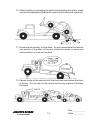
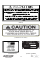
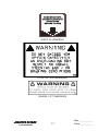
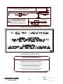
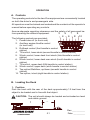
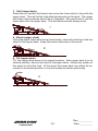
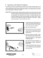
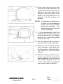
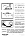
3 CAR CARRIER
OPERATIONS AND MAINTENANCE
MANUAL
13224 Fountainhead Plaza
Hagerstown, MD 21742
Phone (717) 597-7111
www.jerr-dan.com
FOREWORD
This manual is intended to serve as a guide to the owner and operator
in the safe operation and optimum performance of this Jerr-Dan equipment.
Establishment of good operating habits and familiarity with the equipment and its capabilities combined with good judgement are essential.
Before attempting to operate the unit carefully read all sections of this
manual.
TABLE OF CONTENTS
Certification ...................................................................................... 0.1
Safety ............................................................................................... 1.1
Decal Group ..................................................................................... 1.5
Operation .......................................................................................... 2.1
Maintenance and Lubrication ........................................................... 3.1
Lubrication Chart .............................................................................. 3.3
Troubleshooting ................................................................................ 3.4
Rev. __________
1
Date _________
9/14
THIS PAGE INTENTIONALLY LEFT BLANK
Rev. __________
Date _________
NOTICE
MANUFACTURED BY:
DATE OF MANUFACTURE_____mo. _____yr.
INCOMPLETE VEHICLE MANUFACTURED
BY:
DATE INC. VEH. MFD.
_____yr.
_____mo.
GVWR _______________________________
GAWR FRONT _____________________ with
__________________________________tires,
_____ rims, @ _____ psi cold _____________
GAWR INTERMEDIATE (1) ____________with
__________________________________tires,
_____ rims, @ _____ psi cold _____________
GAWR INTERMEDIATE (2) ____________with
__________________________________tires,
_____ rims, @ _____ psi cold _____________
GAWR REAR ______________________with
__________________________________tires,
_____ rims, @ _____ psi cold _____________
Conformity of the chassis-cab to Federal Motor
Vehicle Safety Standards, which have been
previously fully certified by the incomplete vehicle
manufacturer or intermediate vehicle manufacture,
has not been affected by final-stage manufacture.
The vehicle has been completed in accordance
with the prior manufacturer’s instructions, where
applicable. This vehicle conforms to all other
applicable Federal Motor Vehicle Safety Standards
in effect in:
_____mo.
_____yr.
VEHICLE IDENTIFICATION NUMBER:
VEHICLE TYPE: ________________________
This certification sticker appears on every Jerr-Dan unit mounted on a new chassis and
is required by law. Jerr-Dan Corporation will not certify any unit for a capacity greater than
the chassis manufacturer’s specified rating. The capacity ratings of Jerr-Dan units do
not imply that vehicles can be used without regard to gross vehicle weight ratings
(GVWR) or gross axle rating limitations.
The payload carrying capacity of any truck is determined by the GVWR of the cab
chassis, the curb weight of the cab chassis and the weight of the body. It is important that
you determine that your truck has satisfactory carrying capacity and axle ratings for your
specific application. Jerr-Dan’s authorized sales representatives are available to assist
you in this regard.
0.1
Rev. __________
Date _________
THIS PAGE INTENTIONALLY LEFT BLANK
0.2
Rev. __________
Date _________
SAFETY
Safety is all-important when working with machinery. Accidents happen
when established safety practices have been overlooked.
Read and practice all safety points listed in this manual. Safety is the
prime responsibility of the operator.
1. Read operating and loading instructions thoroughly.
2. Become familiar with the loads that your unit can safely transport
without exceeding the structural capacity of the Jerr-Dan equipment
or the gross axle weight ratings, gross vehicle weight rating, and
gross combined vehicle weight rating of your chassis.
3. Observe all warning decals.
4. Make sure you are clear of oncoming traffic. Dual controls (driver’s
side and passenger’s side) are standard on your Jerr-Dan roll back.
5. Always put bumper on the ground to support the body and truck
frame.
6. Never exceed the rated capacity of the body or truck chassis and
it’s components or use a tow option without a vehicle on the deck.
1.1
Rev. __________
Date _________
7. Never winch from the side of the bed. Winch only from the rear
with load in line with the winch. Failure to do so can result in winch
or wire rope damage. JERR-DAN DOES NOT RECOMMEND THE
USE OF SIDE PULLING DEVICES.
8. Always try to winch from the center of the load.
9. Maintain winch cable in good condition. Replace when worn, kinked
or frayed. Do not use cable clamps.
1.2
Rev. __________
Date _________
10. When loading or unloading the deck and operating the winch, make
certain the area behind the load is clear of personnel and obstacles.
11. Distribute load evenly on the deck. Do not concentrate the load on
one section of the deck, to the rear of the truck axles, or use a tow
option without a load on the deck.
12. Secure cargo to the deck at both the front and rear before the truck
is driven. Do not rely on the winch as the only means of holding
the load.
1.3
Rev. __________
Date _________
13. Keep alert. Do not be distracted during any operating sequences.
14. Do not work behind truck with vehicle on deck unless vehicle is
secured at front of deck. (Do not rely on winch.)
15. Read and follow wheel lift instructions for proper towing.
16. Do not exceed tow option ratings. Overloading can cause unsafe
steering and braking conditions.
17. Always use both wheel straps on wheel lift.
18. Use separate safety chains from towed vehicle to subframe for tow
options. Always attach safety chains to the opposite side of the
attaching point, crossing chains under the tow option. Allow enough
slack in the chains to maneuver around corners without binding.
19. Insure deck is in the locked position before traveling.
20. Review operator’s pre-transport checklist located on the headboard
of the deck each time you move a vehicle.
21. Block up deck before performing any service or maintenance work
under deck.
1.4
Rev. __________
Date _________
DECAL GROUP
(STANDARD DECAL, LEFT SIDE)
(STANDARD DECAL, RIGHT SIDE)
(LUBRICATION CHART)
1.5
Rev. __________
1
Date _________
9/14
(WINCH)
CAUTION
MAINTAIN OIL LEVEL WITHIN 1/2" OF
TOP OF SIGHT GAUGE WITH ALL
CYLINDERS FULLY RETRACTED. TORQUE
SIGHT GAUGE BOLTS: 8 FT-LBS MAX.
272-02
(HYDRAULIC OIL LEVEL)
MANUF ACTURED
JL G I NDUSTRIES,
FOR:
IDENT. NO.
MODEL
VERSION
MANUFACTURED BY:
JLG INDUSTRIES, INC.
SERIAL
BY :
INC.
NO.
FOR:
UNDER ONE OR MORE OF
THE FOLLOWING PATENTS:
MODEL NO.
1001 127221-00
5,133,633
5,575,606
5,697,741
5,722,810
5,951,235
6,231,294 B1
6,315,515 B1 6,336,783 B1
6,447,239 B2 7,264,305 B2
OTHER PATENTS PENDING
1001132766-A
(SUBFRAME ID)
1.6
(SERIAL NUMBER)
Rev. __________
1
Date _________
9/14
SLIDE DECK UNTIL
ARROW ALIGNS WITH
FIRST LEVER
BEFORE TILITING
(DECK ALIGNMENT)
(TOW OPTION WARNING)
(WHEEL LIFT WARNING)
1.7
Rev. __________
Date _________
CAUTION
FULLY RETRACT TOW OPTION
BOOM TO AVOID DAMAGE
DURING OPERATION OF OTHER
CARRIER FUNCTIONS.
165
(TOW OPTION WARNING)
(CHECKLIST REMINDER)
1.8
Rev. __________
Date _________
(CHECKLIST)
1.9
Rev. __________
Date _________
381
WINCH FREE SPOOL SYSTEM
LOCATED UNDER MAIN DECK
TO ENGAGE: LIFT UP KNOB
THEN RELEASE. OPERATE
WINCH TO LATCH IN.
WARNING
BEFORE OPERATION - WINCH CLUTCH
MUST BE COMPLETELY ENGAGED WITH
GUIDE BUSHING POSITIONED AS SHOWN
TO DISENGAGE: LIFT
UP KNOB AND PULL
OUT. LOCK IN PLACE.
(FREE-SPOOL OPERATION)
(SLIDE PAD LUBRICATION)
WARNING
WINCH ORBIT MOTOR FITTINGS WILL INTERFERE
WITH NYLON CABLE TRACK SYSTEM UPON
INSTALLATION AND REMOVAL OF DECK.
DO NOT INSTALL ORBIT MOTOR FITTINGS
INTO ORBIT MOTOR TILL DECK IS SLID
COMPLETELY ONTO SUBFRAME.
REMOVE ORBIT MOTOR FITTINGS PRIOR TO
REMOVING DECK FROM SUBFRAME.
330
(ORBIT MOTOR FITTINGS WARNING)
1.10
Rev. __________
Date _________
MANUFACTURED BY: JLG INDUSTRIES, INC.
FOR:
13224 Fountainhead Plaza
Hagerstown, MD 21742
Phone (717) 597-7111
www.jerr-dan.com
MODELNUMBER:
SERIAL NUMBER:
STRUCTURAL CAPACITIES*
MAIN DECK CAPACITY:
LBS.*
UPPER DECK CAPACITY:
LBS.*
WHEELLIFT/TOWBAR LIFT CAPACITY:
(FULL EXTENSION)
LBS.*
WHEELLIFT/TOWBAR TOW CAPACITY:
LBS.*
HITCH OPTION TONGUE CAPACITY:
(FULL RETRACTION)
LBS.*
HITCH OPTION TONGUE CAPACITY:
LBS.*
*PLEASE READ THE FOLLOWING IN
ORDER TO ENSURE SAFE AND
CORRECT USE OF THE EQUIPMENT.
DO NOT EXCEED THE ABOVE STRUCTURAL RATINGS.
THE MAXIMUM EFFECTIVE TRANSPORT LOAD
MAY BE LIMITED BY THE GAWR, GVWR OR GCWR
OF THE TRUCK CHASSIS.
THE MAXIMUM EFFECTIVE TRANSPORT LOAD MAY BE
LIMITED BY THE RATINGS OF ANY TOW IMPLEMENTS,
ATTACHMENTS, OR ACCESSORIES BEING USED.
WHEN SUPPLIED, THE SAFETY LOCKING PIN
MUST BE IN PLACE DURING TRANSPORT TO
ACHIEVE THE RATINGS LISTED ABOVE.
SAFETY IS NO ACCIDENT. REVIEW OPERATOR'S
PRE-TRANSPORT CHECKLIST ON VEHICLE AND IN THE
OWNERS MANUAL EACH TIME YOU MOVE A VEHICLE.
FOLLOW ALL INSTRUCTIONS ON CONTROLS AND UNIT.
1001132765-A
(STRUCTURAL RATING PLACARD)
1.11
Rev. __________
1
Date _________
9/14
THIS PAGE INTENTIONALLY LEFT BLANK
1.12
Rev. __________
Date _________
OPERATION
A. Controls
The operating controls for the Jerr-Dan equipment are conveniently located
on both the driver’s and passenger’s side.
All operators must be trained and understand the contents of the operator’s
manual before operating any controls.
Assure adequate operating clearance and the safety of all personnel before operating the rollback equipment.
3
5
7
9
6
4
8
10
The following controls are provided:
1. Power-take-off (in truck cab)
2. Auxiliary engine throttle control
(in truck cab)
3. Rollback control (first handle in control
station)
4. Tilt control, lower deck (second handle in control station)
5. Winch control, lower deck front winch (third handle in control
station)
6. Winch control, lower deck rear winch (fourth handle in control
station)
7. Tilt control, upper deck (fifth handle in control station)
8. Winch control, upper deck (sixth handle in control station)
9. Tow option/Stabilizer, up/down (seventh handle in control
station)
10. Tow option, in/out (eigth handle in control station)
W
R
W
W
T
I
I
I
I
N
B
L
C
C
H
O
W
O
T
W
A
N
N
L
H
T
S
T
T
I
O
L
L
C
B
A
I
R
L
T
T
H
O
P
T
OPERATING INSTRUCTIONS
ALL OPERATORS SHOULD BE TRAINED AND
COMPLY WITH ALL LOAD RATINGS.
UNDERSTAND THE OPERATOR'S MANUAL.
CAPACITY LOADS MUST BE
UNIFORMLY DISTRIBUTED.
ASSURE SAFETY OF ALL PERSONNEL.
TILT ONLY WHEN DECAL ALIGNS WITH
ADEQUATELY SECURE ALL LOADS.
FIRST CONTROL HANDLE.
ASSURE ENGAGEMENT OF WINCH DRUM.
DO NOT OPERATE IF DAMAGED
OR DEFECTIVE.
ASSURE PROPER MAINTENANCE.
DISENGAGE PTO BEFORE
ENGAGING TRANSMISSION.
USE SAFETY CHAINS FROM SUBFRAME
TO TOWED VEHICLE.
343
B. Loading the Deck
1. Position
Park the truck with the rear of the deck approximately 12 feet from the
object to be loaded and in line with that object.
CAUTION: The unit should always be loaded and unloaded on level
and stable ground.
1
12 FT.
2.1
Rev. __________
Date _________
1a. Set the parking brake.
1b. With the engine running, engage the PTO per instructions in the
truck cab or in the PTO Operating Manual.
1c. Set the auxiliary throttle. After operating the unit several times,
one will establish a feel for the optimum speed. DO NOT
OVERSPEED.
2. Roll
Raise the rollback handle and the deck will slide back. Roll the deck rearward approximately 12 inches to clear the mechanical hold downs at the
front of the frame. A decal is provided on the rubrail to aid in determining
the amount to roll. Align the decal pointer with the roll (first) control handle.
2
SLIDE DECK UNTIL
ARROW ALIGNS WITH
FIRST LEVER
BEFORE TILITING
3. Tilt
Raise the tilt control lever, raising the forward end of the deck until the rear
bumper rests firmly on the ground.
3
4. Roll
Raise the roll handle and the deck will slide back. Continue this operation
until the approach plate of the deck has contacted the ground. Make sure
that the rear bumper and the approach plate are both in firm contact with
the ground before loading. There should be an equal weight distribution
between the rear bumper and the end of the deck.
4
5. Winch
Winch the load onto the deck. Refer to the Winch Operation Manual for
specific winch operation procedures.
5
2.2
Rev. __________
Date _________
5a. Raise the winch control handle to power unreel the winch cable while a
second person keeps the cable taut or disengages the winch clutch
and free spool the cable. (See the Winch Operation Manual for proper
clutch disengagement prodecures)
5b. Engage the winch clutch if the winch cable was free spooled. Raise the
winch handle (unreel the cable)until the winch clutch fully engages.
Ensure that the winch clutch is fully engaged before putting a load on
the winch.
5c. Attach the winch cable to the load. The winch cable should be attached
as close to the center of the load as possible. It may be necessary to
use a “V” chain or other implement to attach the winch cable to the load.
5d. Lower the Winch control handle to wind the cable onto the winch drum
and pull the load onto the deck.
CAUTION: Never disengage the winch clutch when the winch is
under load.
CAUTION: Always maintain a minimum of 5 wraps of cable on the
winch drum.
CAUTION: Always winch load onto deck, NEVER drive equipment
onto the tilted deck.
CAUTION: Always maintain a uniform wrap of cable on the drum.
“Nesting” of the winch cable may cause damage or premature wear of the winch cable.
CAUTION: Remember that cables break, winches fail, and hooks become disengaged. DO NOT WORK BELOW THE LOAD!
CAUTION: Replace worn or damaged cables. Always wear gloves
when handling cable. DO NOT USE CABLE CLAMPS.
CAUTION: The winch cable should remain attached to the load and
taut.
6. Secure Load
Once the load is positioned on the deck secure it from movement in all
directions. Set the parking brake or use wheel chocks if applicable.
2.3
Rev. __________
Date _________
7. Roll
Lower the roll control handle to roll the deck forward until the deck is in the
proper position for tilting. The deck is in the proper position for tilting when
the decal pointer is aligned with or just behind the roll (first) control handle.
7
8. Tilt
Lower the tilt control handle to lower the front of the deck until the deck
lays flat on the slide pads on the hold down.
NOTE: Tilting deck when fully forward will cause damage to the hold
downs.
8
9. Roll
Lower the roll control handle to roll the deck forward until it is in the full
forward position and under the hold downs.
9
10. Secure Load
All loads must be secured from movement in all directions using safety tiedowns. Jerr-Dan provides straps and chains suitable for securing most
vehicles to the deck. Vehicles should be secured at all four corners using
safety tie-downs. Set brakes (if a vehicle) and use wheel blocks and tiedowns for safe transport. Refer to the AAA or vehicle manufacturers
towing manual for correct attachment points.
CAUTION: Use safety tie-downs to secure the load against rearward
motion. Leave the winch cable attatched to the load and
taut, but do not rely on the winch cable to secure the load.
11. Disconnect PTO
Return the engine to normal idle speed and disengage the PTO before
engaging the transmission. Driving the truck with the PTO engaged will
cause overspeeding. Overspeeding of the PTO and/or pump will greatly
shorten their life and can cause damage to the PTO, pump, and transmission.
Rev. __________
Date _________
2.4
C. Unloading the Deck
1. Position
Park the truck with the rear of the deck approximately 12 feet from desired
position of vehicle being unloaded.
1a. Set the parking brake.
1b. With the engine running, engage the PTO per instructions in the
truck cab.
1c. Set the auxiliary throttle. After operating the unit several times
one will establish a feel for the optimum speed. DO NOT
OVERSPEED.
1d. Partially release bindings of the load but maintain restraint against
movement of the load in any direction.
12'+
1
LENGTH
2. Roll
Raise the rollback handle and the deck will slide back. Roll the deck rearward approximately 12 inches to clear the mechanical hold downs at the
front of the frame. A decal is provided on the rubrail to aid in determining
the amount to roll. Align the decal pointer with the roll (first) control handle.
2
SLIDE DECK UNTIL
ARROW ALIGNS WITH
FIRST LEVER
BEFORE TILITING
3. Tilt
Raise the tilt control handle, raising the forward end of the deck until the
rear bumper rests firmly on the ground.
3
2.5
Rev. __________
Date _________
4. Roll
Raise the roll handle and the deck will slide back. Continue this operation
until the approach plate has contacted the ground.Make sure that the rear
bumper and the approach plate are both in firm contact with the ground
before unloading. There should be an equal weight distribution between
the rear bumper and the end of the deck.
4
5. Winch
Winch the load off of the deck. Refer to the Winch Operation Manual for
specific winch operation procedures.
5
5a. Ensure that the winch cable is securely attached to the
load and is taut. Ensure that the winch clutch is fully
engaged (the winch is NOT in free spool mode.)
5b. Remove all equipment used to secure the load to the deck
(excluding the winch cable). Release brakes of the load (if
applicable).
5c. Raise the winch control to power unreel the cable from the
drum, lowering the load from the deck.
5d. Secure the load on the ground Remove the winch cable
from the lod and store the cable.
CAUTION: Never disengage the winch clutch when the winch is
under load.
CAUTION: Always maintain a minimum of 5 wraps of cable on the
winch drum.
CAUTION: Always winch load off of the deck, NEVER drive equipment on the tilted deck.
2.6
Rev. __________
Date _________
CAUTION: Always maintain a uniform wrap of cable on the drum.
“Nesting” of the winch cable may cause damager or premature wear of the winch cable.
CAUTION: Remember that cables break,winches fail,and hooks become disengaged. DON’T WORK BELOW THE LOAD!
CAUTION: Replace worn or damaged cables. Always wear gloves
when handling cable. DO NOT USE CABLE CLAMPS!
D. LOADING THE OVERCAB DECK
1. POSITION
Position the truck with the rear of the deck approximately 12 feet from the
object to be loaded and in line with that object.
CAUTION: The unit should always be loaded and unloaded on level
and stable ground.
1
12 FT.
1a. Set the parking brake.
1b. With the engine running, engage the PTO per instructions in the
truck cab or in the PTO Operating Manual.
1c. Set the auxiliary throttle. After operating the unit several times,
one will establish a feel for the optimum speed. DO NOT
OVERSPEED.
2. Roll
Raise the rollback handle (first lever) and the deck will slide back. Roll the
deck rearward approximately 12 inches to clear the mechanical hold downs
at the front of the frame. A decal is provided on the rubrail to aid in determining the amount to roll. Align the decal pointer with the roll (first) control
handle.
2
SLIDE DECK UNTIL
ARROW ALIGNS WITH
FIRST LEVER
BEFORE TILITING
2.7
Rev. __________
Date _________
3. Tilt
Raise the tilt control lever (second lever), raising the forward end of the
deck until the rear bumper rests firmly on the ground.
3
4. Roll
Raise the roll handle (first lever) and the deck will slide back. Continue this
operation until the approach plate of the deck has contacted the ground.
Make sure that the rear bumper and the approach plate are both in firm
contact with the ground before loading. There should be an equal weight
distribution between the rear bumper and the end of the deck.
4
5. Tilt (upper deck)
Raise the tilt control lever (fifth lever) for the upper deck. This will raise the
front end of the upper deck, raise fully. Free-spool the upper winch and
hook up to the equipment to be loaded.
5
**Note that tilting the upper deck will leave a gap between the
upper and lower decks.
6. Winch (upper deck)
Using the upper deck winch lever (sixth lever), winch the load up the lower
deck approximately three quarters of the way.
6
2.8
Rev. __________
Date _________
7. Roll (lower deck)
Raise the roll handle (first lever) and move the lower deck in line with the
upper deck. This will let the load slide backwards on the deck. The upper
and lower deck surfaces should be in alignment. Be careful not to run the
lower deck into the upper deck. The two decks should barely touch.
7
8. Winch (upper deck)
Using the upper deck winch lever (sixth lever), winch the load up to the tire
stops of the upper deck. Keep the winch cable taut at this point.
8
9. Tilt (upper deck)
Tilt the upper deck down to its original position. After upper deck is in its
stowed position, secure the load to the upper deck. Never rely solely on
the winch to hold the load. At this point the lower deck can either be returned to its stowed position or can be loaded as shown previously.
9
2.9
Rev. __________
Date _________
E. Unloading (upper deck)
Note: The main deck should be empty prior to unloading the top
deck.
1. Tilting
Tilt the upper deck and the lower deck into alignment. Assure that the
upper deck winch cable is taut. Be sure that the load is partially unsecured
prior to titlitng, but maintain restraint against movement in every direction.
1
2. Winch (upper deck)
Release the remaining bindings, except for the winch cable. Winch the
load down onto the main deck until it it centered about half way on the main
deck.
2
3. Roll, Tilt, and Winch
Roll and tilt the lower deck until the approach tip and the bumper tubes are
firmly on the ground. Using the upper winch control, winch the load safely
to the ground. Block the vehicle or apply the emergency brake after the
load is safely on the ground.
3
4. Finish
Finish the process by winching the cable back onto the upper deck winch.
Then tilt the upper deck back into it’s stowed position. Proceed to do the
same process with the lower deck. Be sure that all chains, binders etc. are
secured in a toolbox prior to driving. Be sure that the pto is disengaged
prior to driving, as this may cause damage to the PTO.
2.10
Rev. __________
Date _________
F. Operation of the Wheel Lift (Option)
The wheel lift allows an additional vehicle to be towed damage free on its
own suspension by utilizing a wheel grid similar to the Jerr-Dan HPL wheel
lift. The wheel lift cross bar may also be used as a conventional tow bar for
badly damaged or heavier vehicles.
CAUTION: Because of the additional boom extension and load point of the
towed vehicle, the wheel lift places more load on the rear axle
and unloads the front axle more than a conventional tow bar.
Overloading the wheel lift may result in unsafe steering and
braking conditions and may damage the truck frame. Also,
never use the wheel lift without a vehicle on the deck. Single
vehicle transport should utilize the deck.
1. Position the truck within three (3)
to four (4) feet of the subject vehicle and as close to the direction of the pull as possible.
2a. Set the parking brake.
2b. With the engine running, engage
the PTO per instructions in the
truck cab or in the PTO Operating Manual.
2c. Set the auxiliary throttle. After
operating the unit several times,
one will establish a feel for the
optimum speed. DO NOT
OVERSPEED.
Be sure the towed vehicle is
not in gear or park. Keep the
brake set.
3. Lower the wheel lift arm to about
1-1/2 inches from the ground
and swing the cross bar parallel to the tires.
2.11
Rev. __________
Date _________
4. Set the grid width as required for
the vehicle to be towed. Be sure
both grids are as close to the
center of the boom as possible.
5. To set the grid width, loosen the
“T” handles on the front of the
grid arms and pull the grids out.
Be sure both grids are as close
to the center of the boom as possible, and wide enough to allow
the “L” arms to slide into their
channels. Tighten the “T”
handles to secure the grids.
6. Retract the “Cam” handle locking pin on the grid by turning it a
half turn. It should remain in the
open position.
7. Extend the lift arm under the vehicle being sure that all under
carriage parts are cleared and
that the front portion of the grid
is in contact with both tires.
Lower the grid fully to the
ground. There is no reason for
the operator to get under the
vehicle.
8. Visually inspect the tire to grid
contact before proceeding.
9. Take the “L” arms and slide them
into the channels on the side of
the grid. Insure that they are
resting snugly against the tires,
with the “L” arms in close contact with the tires, reset the locking pin by turning the “Cam”
handle back to the original position. Be sure that the pin seats
in one of the holes. The tires
are now confined front and back.
2.12
Rev. __________
Date _________
10. After securing the grid arm
around the towed vehicles tires
and before making the actual lift,
check to be sure the towed
vehicle’s parking brake is released, the transmission is in
neutral, and the wheels are
straight.
NOTE: If vehicle to be towed is on
a slope, do not release the
brake until the tie-down
straps are installed. Observe the wheels in the grid
for any slippage.
11. It is recommended that the
steering wheel of the towed vehicle be secured in the straight
position by a steering wheel
strap for any tow.
12. Lift the vehicle high enough to
allow the tires to clear ground.
13. Remove the tie-down straps
from toolboxes and attach the
tie-down straps. (See the following section on the tie-down
straps.)
14. With the straps in place, the vehicle in neutral and the parking
brake released, you can move
the vehicle safely up, down, in
or out. All of these movements
are hydraulically controlled.
2.13
Rev. __________
Date _________
15. Raise the vehicle into the final
towing position observing the far
end for sufficient ground clearance. It is possible to set the
rear of a front lifted vehicle completely onto the ground, causing
damage. Take irregular roadsurfaces into consideration.
Observe the lift function from the
side and away from both vehicles if possible. Make sure that
there are no under body components of the towed vehicle in
contact with the “L” arms or
wheel grid device. Readjust if
necessary.
16. Power retract the grid boom until the towed vehicle is about
three (3) to four (4) feet from the
back of the truck. Leave enough
room to maneuver around corners without corner binding or
causing contact between the two
(2) vehicles. Be sure that the
boom is extended at least 4
inches to insure unobstructed
crossbar pivoting.
17. Be sure to maintain sufficient
clearances with the bottom of
the towed vehicle.
18. Attach the safety chains and
magnetic towing lights. SAFETY
CHAINS MUST BE CROSSED.
CAUTION: Always tow with the tow bar extended so that adequate
clearance is maintained between deck and towed vehicle.
CAUTION: Properly secure the vehicle being towed. Use separate
safety chains from towed vehicle to carrier subframe.
2.14
Rev. __________
Date _________
CAUTION: After unloading the vehicle being towed, fully retract the
wheel lift before tilting or rolling the deck.
CAUTION: When not in use, wheel lift must be in upper position and
fully retracted.
CAUTION: The wheel lift option is designed for the transport of an
additional vehicle only. Under no circumstances should a
vehicle be transported on the wheel lift without a vehicle
on the deck as it may cause unsafe steering and braking
conditions. Single vehicle transport should utilize the deck.
CAUTION: When not in use, wheel lift “L” arms must be stored in the
storage tubes provided on the carrier subframe. “L” arms
should never be stored in the wheel grids when not in use.
2.15
Rev. __________
Date _________
TIE-DOWN STRAPS
Your carrier is supplied with a set of high strength polyester web tie-down
straps. They are to be used to secure wheels of the towed vehicle to the
wheel lift grid. NEVER TOW A VEHICLE WITHOUT THE TIE-DOWN
STRAPS INSTALLED.
The tie-down strap assembly is
comprised of two (2) basic components:
1. The strap
2. The ratchet spool mechanism
The following steps should be
followed to properly install the tiedown straps:
USING THE RATCHET SPOOL MECHANISM
1. First the spool must be set into
“free spool”. This is done by pulling the lock bar out and swinging the handle upward until it
rests in the free spool notch and
then simply pulling out the
amount of strap required to fit
over the tire.
2. Now pull on the lock bar and
move it downward until it engages the ratchet teeth on the
take up spool. By pushing and
pulling the handle up and down,
the strap will be wound onto the
spool.
3. To release the ratchet, simply
pull on the locking bar, disengaging the teeth and raise the
handle to the “free spool” position.
Rev. __________
Date _________
2.16
INSTALLING THE TIE-DOWN STRAP
1. With the vehicle lifted just barely
off the ground, attach the strap
to the wheel grid. Be sure the
hook on the ratchet is securely
seated in the “L” arm.
2. Set the ratchet spool in “free
spool” position and pull the
webbed strap out and form a
loop which will wrap around the
tire. Be sure the loop is over a
minimum of 1/3 of the tire.
3. Take up the slack in the strap by
ratcheting the takeup spool arm.
Continue until the tires show
some compression.
4. Raise the wheel grid to the towing position. RE-TIGHTEN THE
RATCHET PERIODICALLY AS
TIRE SETTLES IN GRID FROM
TOWING.
2.17
Rev. __________
Date _________
THIS PAGE INTENTIONALLY LEFT BLANK
2.18
Rev. __________
Date _________
MAINTENANCE AND LUBRICATION
Jerr-Dan rollback truck decks are designed for years of service with little
maintenance. This small amount of maintenance, however, is very important for durability and for safe operation of the deck.
Maintenance is an owner/user responsibility as neither the manufacturer
nor the distributor can normally control this function.
Use only safe practices when maintaining this equipment. Never get under
a tilted deck unless it is adequately supported (don’t rely on the hydraulic
system). Always shut off the engine before reaching into pinch areas as
when checking the hydraulic oil level or greasing under the deck. Maintain
a clean shop for safety. Clean up spilled oil immediately.
Inspect the vehicle and deck system periodically for damage or evidence
of pending failure. Damaged or broken parts should be replaced immediately. Never operate a machine which is known to be defective or operating improperly. The cause of any binding or leakage should be determined
immediately and the problem promptly fixed.
Sliding surfaces of deck beams are to be cleaned and coated with engine
oil periodically. Cleaning every six (6) months is recommended for normal
highway operations, but this frequency will vary appreciably with the type
of service. Sliding on dirty wear surfaces will cause rapid wear. Fittings on
linkage pivots should be greased every two (2) months, again depending
upon usage. See Lube Chart.
Check the hydraulic oil level bimonthly or after any leakage. Use 5W20
Dual Range hydraulic oil. (Automatic transmission fluid may be used in the
hydraulic system if necessary.)
The proper oil level is best checked by rolling the deck back enough to gain
access to the fill plug (unless the chassis configuration caused the oil tank
to be mounted abnormally far to the rear). The oil tank should be about
2/3 full with the deck so positioned (shut off the engine after moving the
deck). This will result in a 3/4 full tank with the cylinders fully retracted
(deck fully forward). (Proper oil level is achieved when the hydraulic oil is
within 1/2 inch of top of sight tube.)
3.1
Rev. __________
Date _________
The hydraulic filter located on the return side of the hydraulic tank comes
equipped with a restriction indicator gauge. This gauge shows the operator the condition of the filter element. When the needle reaches the red
band (25 psi), the filter is starting to bypass and the element needs to be
changed. Failure to change the element will result in premature wear and/
or failure of any or all of the hydraulic components. Only check gauge
with hydraulic fluid at operating temperatures. Cold oil is more dense
and will give a false indicator gauge reading.
If a cylinder seal leaks, disassemble the cylinder and ascertain the cause
of the leak. Small scores caused by chips or contaminated fluid can usually be worked out with fine emory cloth to avoid repetition of the trouble.
Whenever any seal replacement is necessary, it is always advisable to
replace all seals in that component. These seals are available in kits. Also,
thoroughly clean all components before reassembly.
3.2
Rev. __________
Date _________
3.3
Rev. __________
Date _________
TROUBLESHOOTING
PROBLEM
CAUSE
SOLUTION
PROBLEMS ENCOUNTERED WHILE UNIT IS IN TRANSIT
Looseness and rattling
of deck
a. Loose Hold Down Blocks
a. Shim Hold Down Blocks as
required.
WINCH FUNCTIONING IMPROPERLY
Winch screeches during a. Insufficient lubrication
operation
Winch will not pull load a. Free spooling device
on deck
disengaged
b. Insufficient Relief Valve
pressure
c. Sheared keys or broken
chain at coupling
d. Hydraulic pump worn
Cable build-up on one a. Off centered load
side of spool or other
a. Lubricate per lube chart
a. Engage
b. Reset to correct setting
using gauge
c. Inspect and replace
d. Inspect and replace
a. Recenter load if possible
VALVE BANK FUNCTIONING IMPROPERLY
Valve bypasses oil or
squeals during all
operations
Valve handles stick,
tight or frozen
Valve leaks at top or
bottom of spools
a. Insufficient relief valve
setting
b. Broken relief spring
b. Broken centering spring
or clogged with dirt at
bottom of spool
a. Defective seals
a. Reset to correct setting using
gauge
b. Inspect and replace
b. Inspect, clean or replace
a. Replace
CYLINDERS FUNCTIONING IMPROPERLY
Cylinders leak oil
Erratic operation of
cylinders
a. Defective seals or rod
a. Air in hydraulic system
a. Inspect and replace
a. Cycle hydraulic system
10-15 times to remove air
b. Defective pump (Pulsating) b. Replace if necessary
HYDRAULIC SYSTEM FUNCTIONING IMPROPERLY
Slow Operation
a. Low engine RPM
b. Low oil level
c. Blocked, restricted or
collapsed hoses
d. Dirty hydraulic oil
e. Hydraulic pump worn
f. Relief valve in valve bank
bypassing
3.4
a. Speed up engine
b. Reservoir should be 3/4 full
with cylinders retracted
c. Inspect, remove blockage or
reposition hoses affected
d. Drain, flush and refill with
clean oil
e. Rebuild or replace
f. 1) Reset to correct pressure
using gauge
2) Check if relief spring is
broken. Replace if
necessary
Rev. __________
Date _________
TROUBLESHOOTING
PROBLEM
CAUSE
SOLUTION
P.T.O. FUNCTIONING IMPROPERLY
Cable tight or frozen
Rattling noise in P.T.O.
a. Cable kinked or bent
b. Cable and P.T.O. connection not adjusted properly
c. Mounting bracket nuts are
over tightened at P.T.O.
knob
a. P.T.O. backlash too loose
Howling noise in P.T.O. a. P.T.O. backlash too tight
Gear oil leak between
P.T.O. and pump
P.T.O. will not engage
or disengage
a. Defective shaft seal
a. Cable and P.T.O. connection not adjusted properly
b. Defective shifter cover
plate
a. Straighten or replace
b. Inspect and adjust
c. Loosen if necessary
a. Shims must be removed
(Consult P.T.O. manual)
a. Shims must be added
(Consult P.T.O. manual)
a. Remove and replace
a. Inspect and adjust
b. Inspect and replace
HYDRAULIC PUMP FUNCTIONING IMPROPERLY
Cavitation: pump
unusually noisy
Pump takes too long
to respond or fails to
respond
Oil Heating up
Oil foaming
a. Low oil supply
b. Heavy oil
c. Dirty oil filter
d. Restriction in suction line
a. Low oil supply
b. Insufficient relief valve
pressure
c. Pump worn or damaged
a. Foreign material lodged in
relief valve
b. Using too light oil
c. Dirty oil
d. Oil level too low
e. Insufficient relief valve
pressure
f. Relief valve pressure too
high
g. Pump worn (slippage)
a. Air leaking into suction line
from tank to pump
b. Wrong kind of oil
c. Oil level too low
Hydraulic oil leak bea. Defective shaft seal
tween P.T.O. and pump
Pump leaks at front
a. Defective seals
and rear covers
3.5
a. Fill to proper level
b. Fill with proper oil
c. Clean or replace
d. Remove
a. Fill to proper level
b. Reset to correct setting
using gauge
c. Repair or replace
a. Inspect and remove
b. Drain and refill with clean oil
c. Drain, flush, and refill with
clean oil
d. Fill to proper level
e. Set to correct setting using
gauge
f. Same as “e”
g. Repair or replace
a. Tighten all connections
b. Drain and refill with nonfoaming type hydraulic oil
c. Fill to proper level
a. Replace shaft seal
a. Replace seals
Rev. __________
Date _________
THIS PAGE INTENTIONALLY LEFT BLANK
3.6
Rev. __________
Date _________
5376000077- 1