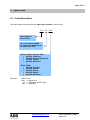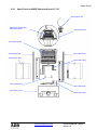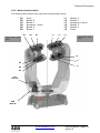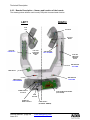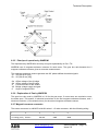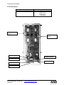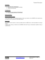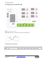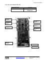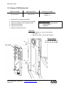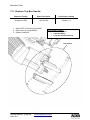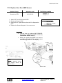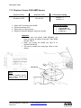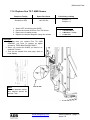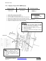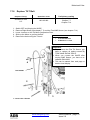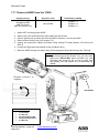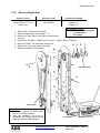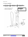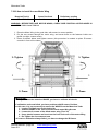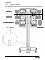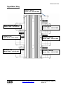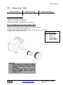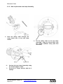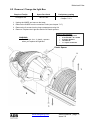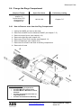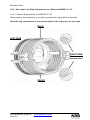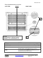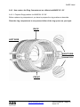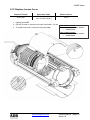
1
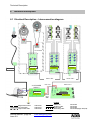
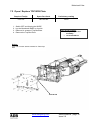
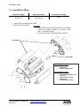
Motorised WARP Service Manual Issue 0.9 Lighting Technologies M 5083 1106.55.083 Foreword Foreword This version 0.9 of the Service Manual for Motorised WARP precedes the complete manual for the Motorised WARP. The latest version of ADB Service Manuals is available from the ADB website. www.adblighting.com For WARP and Motorised WARP www.adblighting.com > ADB Products > Theatre Luminaires > WARP Motorised The latest software version is available on the ADB TTV R&D web site. http://adbttv.dyndns.org/index.php?title=Warp&article=warp Personalities for various lighting control desks can be downloaded from the ADB website. www.adblighting.com Zaventem, 15 June 2006 www.adblighting.com Service Manual - page 1 Issue 0.9 Index Index FOREWORD ........................................................................................................................................... 1 INDEX ...................................................................................................................................................... 2 1 INTRODUCTION ............................................................................................................................ 4 ABOUT THIS GUIDE ................................................................................................................................ 4 2 LEVEL MAINTENANCE DESCRIPTION ....................................................................................... 5 2.1 LEVEL DESCRIPTION ................................................................................................................. 5 3 TOOLS............................................................................................................................................ 6 4 SPARE PARTS .............................................................................................................................. 7 4.1 CODE DESCRIPTION ................................................................................................................. 7 4.2 SPARE PARTS FOR THE MOTORISED WARP HEAD..................................................................... 8 4.2.1 Spare Parts for WARP Motorised head 12°-30° ................................................................ 9 4.2.2 Spare Parts for WARP Motorised head 22°-50° .............................................................. 10 4.3 SPARE PARTS FOR THE MOTORISED YOKE .............................................................................. 11 5 TROUBLE SHOOTING ................................................................................................................ 13 5.1 5.2 5.3 5.4 5.5 5.6 6 PROBLEMS WITH THE LAMP ..................................................................................................... 13 PROBLEMS WITH TOP-BOX AND DISPLAY ................................................................................. 14 PROBLEMS WITH PAN & TILT ................................................................................................... 15 PROBLEMS WITH SHUTTERS .................................................................................................... 16 PROBLEMS WITH ACCESSORIES ............................................................................................... 18 PROBLEMS WITH LENSES ........................................................................................................ 19 TECHNICAL DESCRIPTION ....................................................................................................... 20 6.1 ELECTRICAL DESCRIPTION – INTERCONNECTION DIAGRAM........................................................ 20 6.2 EXPLANATION OF THE INTERCONNECTION DIAGRAM .................................................................. 21 6.2.1 24 V Power Supply .......................................................................................................... 22 6.2.1.1 Description ................................................................................................................................ 22 6.2.1.2 How to know that the 24 V Power Supply present. ................................................................... 22 6.2.2 Motors functionalities ....................................................................................................... 23 6.2.3 Boards Description – Names and location of the boards ................................................ 24 6.3 GENERAL DESCRIPTION .......................................................................................................... 25 6.3.1 Motherboard (Topbox board) ........................................................................................... 25 6.3.2 Pan & Tilt driver board PCB 1525.................................................................................... 28 6.3.3 Magneto-resistance sensors............................................................................................ 28 6.3.4 Principe of operation (1) .................................................................................................. 28 6.3.5 Principe of operation by WARP/M ................................................................................... 29 6.3.6 Explanation of Pan by WARP/M ...................................................................................... 29 6.4 WHEELS DRIVER BOARD PCB 1525......................................................................................... 32 6.4.3 Right 6 Drivers Board ...................................................................................................... 35 6.5 WARPLINK - INTER BOARD COMMUNICATIONS PROTOCOL ........................................................ 37 6.5.1 Transceivers and Termination ......................................................................................... 37 6.5.2 Medium ............................................................................................................................ 37 6.5.3 Byte Format ..................................................................................................................... 37 6.5.4 WarpLink connectors ....................................................................................................... 37 7 MOTORISED YOKE - MAINTENANCE SHEET .......................................................................... 38 7.1 7.2 7.3 7.4 7.5 DISASSEMBLING ARM COVER AND LID FOR PAN AXIS .............................................................. 38 OPEN / REPLACE TOP BOX PLATE ......................................................................................... 39 OPEN MOTOR WING ............................................................................................................... 40 REPLACE 24 V DC POWER SUPPLY ........................................................................................ 41 REPLACE FRONT PANEL ......................................................................................................... 42 Service Manual - page 2 Issue 0.9 www.adblighting.com Index 7.6 REPLACE TOP BOARD PCB .................................................................................................... 43 7.7 CHANGE MOTOR BOARD RIGHT .............................................................................................. 44 7.8 REPLACE PCB PAN & TILT ..................................................................................................... 45 7.9 REPLACE PCB SHUTTER LEFT ................................................................................................ 46 7.10 REPLACE LAMP RELAY BOARD ................................................................................................ 47 7.11 REPLACE TOP BOX HANDLE .................................................................................................... 48 7.12 REPLACE FINE PAN AMR SENSOR .......................................................................................... 49 7.13 REPLACE COARSE PAN AMR SENSOR ................................................................................... 50 7.14 REPLACE FINE TILT AMR SENSOR ......................................................................................... 51 7.15 REPLACE COARSE TILT AMR SENSOR ................................................................................... 52 7.16 REPLACE TILT BELT............................................................................................................... 53 7.17 REMOVE WARP FROM THE YOKE .......................................................................................... 54 7.18 REMOVE RIGHT ARM .............................................................................................................. 55 7.19 REPLACE TILT MOTOR .......................................................................................................... 56 7.20 REPLACE TILT SHAFT & PULLEY ........................................................................................ 57 7.21 REMOVE COARSE TILT RING .................................................................................................. 58 7.22 REPLACE MOTOR WING .......................................................................................................... 59 7.22.1 How to remove the Motor Wing ................................................................................... 59 7.22.2 How to install the new Motor Wing .............................................................................. 60 7.22.2.1 7.22.2.2 Right Motor Wing position .................................................................................................... 61 Left Motor Wing position....................................................................................................... 62 7.23 REMOVE PAN MOTOR ............................................................................................................. 63 7.24 REMOVE YOKE FROM TOP BOX ............................................................................................... 64 7.24.1 Remove Yoke from the Top Box ................................................................................. 64 7.24.2 How to replace the motorised yoke on the Top Box ................................................... 65 7.25 7.25 REPLACE PAN BELT AND COARSE GEAR .......................................................................... 66 7.26 IR SENSOR ............................................................................................................................ 67 7.27 IR SENSOR SETTING .............................................................................................................. 68 7.28 MOTOR WING ......................................................................................................................... 70 7.29 CHANGE MOTOR GEARS......................................................................................................... 71 7.30 ADJUST MOTORS IN THE MOTOR WING .................................................................................... 72 8 WARP HEAD - MAINTENANCE SHEET ..................................................................................... 73 8.1 HOW TO CHANGE THE LAMP ASSEMBLY .................................................................................... 73 8.1.1 How to remove the old lamp Assembly ........................................................................... 73 8.1.2 How to place the new lamp Assembly ............................................................................. 74 8.2 REMOVE / CHANGE THE LIGHT BOX ......................................................................................... 75 8.3 REPLACE THE REFLECTOR ...................................................................................................... 76 8.4 CHANGE THE RINGS COMPARTMENT ....................................................................................... 77 8.4.1 How to Remove arms from the Ring Compartment......................................................... 77 8.4.2 How replace the Ring Compartment on a Motorized WARP 12°-30° ............................. 78 8.4.2.1 Prepare Rings position for WARP/M 12°-30° ............................................................................ 78 8.4.2.2 Introduce Rings Compartment between lenses Arm on the WARP/M 12°-30° ........................ 80 8.4.3 How replace the Ring Compartment on a Motorized WARP 22°-50° ............................. 81 8.4.3.1 Prepare Rings position for WARP/M 22°-50° ........................................................................... 81 8.4.3.2 Introduce Rings Compartment between lenses Arms on the WARP/M 22°-50° ...................... 83 8.5 8.6 8.7 8.8 8.9 8.10 8.11 8.12 8.13 9 REPLACE THE BACK LENS ON 12°-30° WARP ......................................................................... 84 REPLACE THE FRONT LENS ON 12°-30° WARP ....................................................................... 85 REPLACE THE BACK LENS ON 22°-50° WARP ......................................................................... 86 REPLACE THE FRONT LENS ON 22°-50° WARP ....................................................................... 87 CHANGE GEARS & BELTS ON 12°-30° ..................................................................................... 88 REPLACE TEFLON RING .......................................................................................................... 89 REMOVE / CHANGE FRONT FILTER CASSETTE .......................................................................... 90 REPLACE LENSES COVER ....................................................................................................... 91 REPLACE DIAPHRAGM ............................................................................................................ 92 PERSONAL NOTES..................................................................................................................... 93 www.adblighting.com Service Manual - page 3 Issue 0.9 Introduction 1 Introduction About This Guide This manual is for the service and maintenance of WARP/M. It is intended to serve as a reference for personnel who are trained in the service and repair of the WARP/M. WARP/M is warranted for one (1) year from the date of purchase. ADB assumes no responsibility for damage to units occurring from improper service or being adjusted contrary to these instructions. These units will not be covered by this warranty. The following procedures are designed to be performed by a qualified service technician. This document is intended as a guide and does not provide the detail necessary for a novice to make repairs. “Spare Parts Kit” list contains the parts required to make repairs described in this document. Always disconnect the power to the system before dismantling any component to avoid shorts and possible component damage. Service Manual - page 4 Issue 0.9 www.adblighting.com Level Maintenance Description 2 Level Maintenance Description 2.1 Level Description The following chart describes three Maintenance levels: Level Description Documentation Who: Users Theatre Technician Level 1 Level 2 Action: Usual Maintenance Cleaning Head Adjusting Change Fuses Clean IR Sensor All access into Web Page Load a new Software Who: Technician with ADB Training User Manual Action: Access to all functions for normal operator Replace mechanical sub-assembly Replace Board Change Ring Compartment Send Back sub-assembly to ADB After Sales Who: ADB After Sales or equivalent Level 3 Action: All access User Manual + Service Manual Internal ADB Documentation This guide is for qualified service technician level 2 and level 3. To become a qualified service technician level 2 a special training is necessary. Information about the level 2 trainings, please ask your local dealer or contact ADB. www.adblighting.com Service Manual - page 5 Issue 0.9 Tools 3 Tools Adequate tools are required to service the WARP/M. ADB assumes no responsibility for damage to units occurring from improper tools. These units will not be covered by this warranty. List of tools: • Screwdriver Philips Standard # 0 • Screwdriver Philips Standard # 1 • Screwdriver Philips Standard # 2 • Screwdriver Positive Standard # 0 • Screwdriver Positive Standard # 1 • Screwdriver Positive Standard # 2 • Screwdriver Flat 1 • Screwdriver Flat 2 • Screwdriver Flat 3 • Nut driver set metric • Hex. driver set metric • Pliers • Cutter, pliers wrench set Service Manual - page 6 Issue 0.9 www.adblighting.com Spare Parts 4 Spare Parts 4.1 Code Description The chart below describes how the “Spare part numbers” are build-up. 1001 . 6X . XXX Start digits for Spare Parts 60: Conventional WARP 61: Motorised WARP Head 65: Motorised Yoke 1001.60. XXX to 1001.61.XXX: 000-190: Light Box 200-290: Ring Compartment 300-590: Lenses 800-990: Mechanic 1001.65.XXX: 000-190: Top Box 200-390: Boards 400-590: Wiring 600-790: Motors 800-990: Mechanic Example : 1001.61.000 1001 => spare part 61 => Motorised WARP Head 000 => Light Box www.adblighting.com Service Manual - page 7 Issue 0.9 Spare Parts 4.2 Spare Parts for the Motorised WARP Head Warning: Spare parts for Motorised WARP head (luminaire) are different from conventional WARP. The chart describes the sub assembly, the code number and the chapter refer to the technical information in this manual. Sub Assembly WARP Lamp Assembly Reflector for halogen lamp Complete Light Box Code Number 1001.61.000 1001.61.010 1001.61.020 Chapter 8.1 8.3 8.2 Sub Assembly Complete Ring Compartment 12°-30° Complete Ring Compartment 22°-50° Code Number 1001.61.200 1001.61.210 Chapter 8.4.2 8.4.3 Sub Assembly Rear Lens 12°-30° Kit Front Lens 12°-30° Kit Rear Lens 22°-50° Kit Front Lens 22°-50° Kit Belt Kit for WARP/M 12°-30° Belt Kit for WARP/M 22°-50 Teflon Ring Kit Diaphragm 12°-30° Diaphragm 22°-50° Code Number 1001.61.300 1001.61.310 1001.61.320 1001.61.330 1001.61.340 1001.61.350 1001.61.360 1001.61.370 1001.61.380 Chapter 8.5 8.6 8.7 8.8 8.9 8.9 8.10 8.13 8.13 Sub Assembly Focus Arm 12°-30° Zoom Arm 12°-30° Focus Arm 22°-50° Zoom Arm 22°-50° Code Number 1001.61.400 1001.61.410 1001.61.420 1001.61.430 Chapter 8.9 8.9 8.9 8.9 Sub Assembly Colour Filter Cassette Lenses Cover 12°-30° Lenses Cover 22°-50° Code Number 1001.61.500 1001.61.510 1001.61.520 Chapter 8.11 8.12 8.12 Service Manual - page 8 Issue 0.9 www.adblighting.com Spare Parts 4.2.1 Spare Parts for WARP Motorised head 12°-30° 1001.61.000 (ch 8.1) Reflector for halogen lamp 1001.61.010 (ch 8.3) 1001.61.020 (ch 8.2) 1001.61.200 (ch 8.4.2) 1001.61.400 (ch 8.9) 1001.61.410 (ch 8.9) 1001.61.510 (ch 8.12) 1001.61.300 (ch 8.5) 1001.61.370 (ch 8.13) 1001.61.340 (ch 8.9) 1001.61.500 (ch 8.11) 1001.61.310 (ch 8.6) www.adblighting.com Service Manual - page 9 Issue 0.9 Spare Parts 4.2.2 Spare Parts for WARP Motorised head 22°-50° 1001.61.000 (ch 8.1) Reflector for halogen lamp 1001.61.010 (ch 8.3) 1001.61.020 (ch 8.2) 1001.61.210 (ch 8.4.3) 1001.61.430 (ch 8.9) 1001.61.420 (ch 8.9) 1001.61.520 (ch 8.12) 1001.61.320 (ch 8.7) 1001.61.350 (ch 8.9) 1001.61.330 (ch 8.8) 1001.61.380 (ch 8.13) 1001.61.500 (ch 8.11) Service Manual - page 10 Issue 0.9 www.adblighting.com Spare Parts 4.3 Spare Parts for the Motorised Yoke The chart describes the sub assembly, the code number and the chapter refer to the technical information in this manual. Sub Assembly Top Box Front panel Assembly 24 v DC Power Supply Top Box Plate Top Box Handle Sub Assembly Pan & Tilt Motordriver + Cooling Assy Left Motordriver + Cooling Assy Right Motordriver + Cooling Assy Kit Magnet Sensor Kit PCB Lamp Control Kit Infra Red Sensor Right Kit Infra Red Sensor Left Kit XLR-4 pts Top Box Board Fuses Kit Sub Assembly Main Power Supply Cable Lamp Cable Cable Kit Top Box Kit WARP Link WARP Link 1 WARP Link 2 WARP Link 3 Kit IR Sensor Cable Kit AMR Sensor Cable Kit cable loom Right Motor Kit cable loom Left Motor Kit cable loom Pan&Tilt Motor Kit XLR 4 pts Cable Kit Cable Lamp Control Sub Assembly Pan Motor Assy Tilt Motor Assy Zoom Focus Motor Assy Shutter Motor Assy Bottom Shutter Motor Assy Top Gobo Motor Assy Top Gear Ring Kit Pan Belt Tilt Belt Sub Assembly Pan & Tilt Pulley Coarse Gear with Magnet Pan Axis Tilt Axis Motor Wing Covers Top Yoke cover Complete Yoke Structure Code Number 1001.65.000 1001.65.010 1001.65.020 1001.65.030 Code Number 1001.65.200 1001.65.210 1001.65.220 1001.65.230 1001.65.240 1001.65.260 1001.65.270 1001.65.280 1001.65.290 1001.65.300 Code Number 1001.65.400 1001.65.410 1001.65.420 1001.65.430 1001.65.431 1001.65.432 1001.65.433 1001.65.440 1001.65.450 1001.65.460 1001.65.470 1001.65.480 1001.65.490 1001.65.500 Code Number 1001.65.600 1001.65.610 1001.65.620 1001.65.630 1001.65.640 1001.65.650 1001.65.660 1001.65.670 1001.65.680 Code Number 1001.65.800 1001.65.810 1001.65.820 1001.65.830 1001.65.840 1001.65.850 1001.65.870 www.adblighting.com Chapter 7.5 7.4 7.2 7.11 Chapter 7.8 7.9 7.7 7.12 to 7.15 7.10 7.26 7.26 7.3 7.6 6.3.1 Chapter 6.1 6.1 6.1 6.1 6.1 6.1 6.1 6.1 6.1 6.1 6.1 6.1 6.1 6.1 Chapter 7.23 7.19 7.25 7.16 Chapter 7.23 7.21 – 7.25 7.25 7.20 7.3 7.1 Service Manual - page 11 Issue 0.9 Spare Parts Connector cable Power Motorised right arm Service Manual - page 12 Issue 0.9 1001.65.880 1001.65.890 www.adblighting.com 7.17 7.18 Trouble Shooting 5 Trouble Shooting 5.1 Problems with the lamp This Trouble shooting for WARP without Internal Dimmer Trouble/Symptom Lamp flasher at power On Origin Normal on old Version NO Solution Start the WARP/M with lamp Dimmer at 0% Put a Lamp in No Lamp NO No good inserted lamp Fully the lamp insert NO No Power from Dimmer Connect to an external dimmer NO No Direct Power Connect to mains NO Lamp OFF on Web page See Web Page (User Manual) NO Lamp stays off after power On Lamp OFF on Display Go to Menu Man/Lamp/AUTO or ON into Display NO Relay PCB is faulty Change Relay PCB (see chapter 7.10) NO Pan & Tilt Board Lost Replace Pan &Tilt Board(see chapter Software (LEDs on the board 7.8) stay off) NO Topbox board never Starts Replace topbox board (see chapter 7.5 and 7.6) No 24 V Power Supply (Power Replace power chapter 7.4) LED is off) www.adblighting.com supply board Service Manual - page 13 Issue 0.9 (see Trouble Shooting 5.2 Problems with Top-Box and Display Trouble/Symptom Origin Main Supply Fuse is blown NO Solution Control and Change Main Fuse (see user Manual) 24 V Cable Unplugged or Control 24 V power supply Connection Ground and +24 v wire inverted (see chapter 6.1 for electrical connection) NO No Display after 1 min. power On 24 V Supply Out of order (see Replace 24 V power supply (see chapter 6.3.1 to verify chapter 7.4) voltages) NO Top Box Board Out of order Replace top Box Board (see chapter 7.5) Bad Ethernet Connection Control and replace external Data Cable (Ethernet LED must flicker) NO No Control of the WARP by Art Net Bad Ethernet Configuration Service Manual - page 14 Issue 0.9 www.adblighting.com Control Sub-net and Universe on the WARP Web Page Trouble Shooting 5.3 Problems with Pan & Tilt Important: On this chapter, consider that Top Board and 24V Power Supply are not damaged Trouble/Symptom Origin Move the yoke manually and control if there is motor resistance Solution NO Pan “or” Tilt don’t Move Pan “or” Tilt Fuse is warm Replace warm fuse (see chapter 6.3.3) NO Pan & Tilt Board is out of order Replace Pan & Tilt Board Bad Calibration of Pan or Tilt Re- Calibrate Pan & Tilt NO One of the 2 sensors (fine and Control all Sensor connections and wiring coarse) is disconnected NO Pan “or” Tilt is not Stable One of the 2 sensors (fine and Replace Fine and Coarse AMR sensors (See chapter 7.12 for Pan and 7.13 for coarse) is damaged Tilt) NO Pan and Tilt Board is damaged Replace Pan & Tilt Board (see chapter 7.8) Re- Calibrate Pan “or” Tilt Bad Calibration of Pan or Tilt NO Pan “or” Tilt make noise at 0 or Full after resetting Wiring problem between AMR Control and change damaged wire Sensors and Board NO One of the 2 sensors (fine and Replace Fine and Coarse AMR sensors (See chapter 7.12 for Pan and 7.13 for coarse) is damaged Tilt) www.adblighting.com Service Manual - page 15 Issue 0.9 Trouble Shooting 5.4 Problems with Shutters Important: On this chapter, consider that Top Board and 24V Power Supply are working properly Trouble/Symptom Origin WARP Link 1 Damaged Solution Control and replace WARP Link 1 NO Some shutters don’t respond Right Board is (orange LED is off) damaged Replace Board Chapter 7.7) 1001.65.220 (see damaged Replace Board chapter 7.9) 1001.65.210 (see NO Left Board is (orange LED is off) Too much dust or oil (from Clean all IR sensors (right and left) with air cleaner or alcohol smoke machine) NO Right IR sensor is disconnect Control connection and replace cable if Calibration on Shutters A and or Right IR sensor cable is necessary damaged D always fails NO A and D damaged IR Sensor is Replace Right IR sensor (see chapter 7.26) Too much dust or oil (from Clean all IR sensors (right and left) with air cleaner or alcohol smoke machine) NO Left IR sensor is disconnect or Control connection and replace cable if Calibration on Shutters B and Left IR sensor cable is necessary damaged C always fails NO A and D damaged Service Manual - page 16 Issue 0.9 IR Sensor www.adblighting.com is Replace Left IR sensor (see chapter 7.26) Trouble Shooting Trouble/Symptom Origin Bad Calibration Solution Calibrate the failed shutter NO Dusty sensor Clean all IR Sensors NO Silver white index mark on the Use special silvered paint and a small brush to paint the index ring is erased NO One shutter has always bad reset (but no error message on display) The motor wing is not well Place the motor correctly (see chapter placed (IR sensor not in front 7.22.2) of Ring Index) NO Motor of the failed shutter is Place correctly the corner plate behind mechanically forced (noises in motors: small mechanical clearance motor gear, motor slips or behind all 3 motors (See Chapter 7.28) skids) www.adblighting.com Service Manual - page 17 Issue 0.9 Trouble Shooting 5.5 Problems with accessories Trouble/Symptom Origin Solution Too much dust or oil (from Clean all IR sensors (right and left) with smoke machine) air cleaner or alcohol NO Right or Left IR sensor is Control connection and replace cable if disconnected needed Calibration on one Accessory Right or Left IR sensor cable always fails is damaged NO Accessory damaged IR Sensor Bad Calibration is Replace Right or Left IR sensor (see chapter 7.25) Calibrate the failed Accessory NO Dusty sensor Clean all IR Sensor NO Index on the ring is erased Use special silvered paint and a small brush to paint the index NO One Accessory has always bad reset (but no error message on display) The motor wing is not well Place the motor correctly (see chapter placed (IR sensor not in front 7.22.2) of ring Index) NO Motor of the failed Accessory Place correctly the corner plate behind is mechanically forced (noises motors: small mechanical clearance in motor gear, motor slip or behind all 3 motors (see Chapter 7.28) skid) Service Manual - page 18 Issue 0.9 www.adblighting.com Trouble Shooting 5.6 Problems with lenses Trouble/Symptom Origin Solution One lens cover is inversed and Replace correctly the lens cover the Safety Cable blocks the Lens NO Front Lens has poor repeatability Plastic gears between Motor Replace All Gears on the Front Lens Motor (See chapter 7.29) and Ring are damaged NO Motor of the front Lens is Place correctly the corner plate behind mechanically forced (noises in motors: small mechanical clearance motor gear, motor slips or behind all 3 motors (see Chapter 7.28) skids) www.adblighting.com Service Manual - page 19 Issue 0.9 Technical Description 6 Technical Description 6.1 Electrical Description – Interconnection diagram TILT MOTOR 1001-65-240 1001-65-200 1001-65-210 1001-65-220 PCB 1525 PCB 1525 PCB 1525 WARP LINK3 24 V POWER SUPPLY WARP LINK 2 RED +24V WARP LINK 1 BLUE BLACK 1001-65-010 1001-65-000 PCB 1525 PCB 1525 Black GND LEGEND: Magnet Sensor Cable Pan & Tilt Cable Lamp Control Cable Service Manual - page 20 Issue 0.9 1001.65.440 1001.65.470 1001.65.490 www.adblighting.com WARP Link IR Sensor Cable XLR 4 Cable Motor Wing Cable 1001.65.420 1001.65.430 1001.65.480 1001.65.450 (Right) .460 (Left) Technical Description 6.2 Explanation of the interconnection diagram WARP/M has 14 “3 phase steppers”. Those steppers are controlled by 3 drive-boards (PCB 1525). The position of the steppers for pan/tilt is detected by Magneto-resistance sensors; for the other functions by Opto sensor. All control and feedback information is centralized in the Main processor board; top box (PCB 1525). The communication, between the different parts is called WARP link protocol. Below each part in detail: www.adblighting.com Service Manual - page 21 Issue 0.9 Technical Description 6.2.1 24 V Power Supply 6.2.1.1 Description SPARE PART CODE 1001.65.010 LOCATION TOP BOX LINKS In: Mains Voltage Out: Top Board The WARP/M is powered with 198 - 264 V AC, +/- 50/60 Hz (optional: universal power supply 90 – 264 V, +/- 50/60 Hz). The connector is Neutrix PowerCon locking. The WARP/M is protected with a fuse of 6.3 A 250V SPT 5 x 20 mm. The lamp power is coming from an external dimmer. Power Supply Fuse Lamp Supply 6.2.1.2 How to know that the 24 V Power Supply present. It the “power” LED is on at power up of the WARP/M the 24 V supply is present. If the power LED is off the 24 V power supply is not available. (refer to chapter 7.4.) For the early production units (production batch 1 to 10) the LED will only light up after the booting of the WARP/M (+/- 1 min). A quick way to check if the 24 V power supply is present is trying to move the yoke just after power on. If Pan & Tilt Motors give resistance, the 24 V is present; if not, control the supply (refer to chapter 7.4.). Service Manual - page 22 Issue 0.9 www.adblighting.com Technical Description 6.2.2 Motors functionalities The drawing below defines each motor with his associated function. Focal Shutter 4 Shutter 1 Accessory 1 (rear) Shutter 4 Shutter 1 R1 R2 R3 R4 R5 R6 R3 R2 R1 L1 L2 L3 L4 L5 L6 L1 L2 Shutter 2 Shutter 3 Accessory 2 (front) Shutter 2 Shutter 3 Zoom L3 Left hand motor wing Right hand motor wing L6 L5 R6 L4 R5 R4 TILT MOTOR PAN MOTOR www.adblighting.com Service Manual - page 23 Issue 0.9 Technical Description 6.2.3 Boards Description – Names and location of the boards The drawing below defines each board (PCB) with his associated function. RIGTH LEFT PCB 1527 PCB XLR4 PCB 1527 RIGHT PCB 1525 PCB 1525 6 MOTORS DRIVERS LEFT PAN & TILT AMR SENSOR TILT COARSE PCB 1525 6 MOTORS DRIVERS RIGHT AMR SENSOR TILT FINE LAMP RELAY AMR SENSOR AMR SENSOR PAN FINE PAN COARSE POWER SUPPLY 24 VOLTS PCB 1496 MOTHER BOARD (TOP BOARD) FUSE HOLDER POWER ON DIRECT SUPPLY Service Manual - page 24 Issue 0.9 LAMP SUPPLY (EXTERNAL DIMMER) www.adblighting.com Technical Description 6.3 General description • • • The WARP/M is a motorized profile spotlight with 3 – phase steppers on all functions. The user interface is accessible by the display and the buttons The control is by DMX512 and Ethernet (ArtDMX). 6.3.1 Motherboard (Topbox board) 6.3.1.1 Block scheme CPU is a Motorola 32 bit (ColdFire range) with on-chip peripherals including 2 UARTs and Ethernet. TCPIP stacks and web-page browser is running on LINUX. CPLD (Complex Programmable Logic Device). 6.3.1.2 Description SPARE PART CODE LOCATION LINK www.adblighting.com 1001.65.290 TOP BOX 24 V Power Supply WARP Link 1 Ground Service Manual - page 25 Issue 0.9 Technical Description 6.3.1.3 PCB 1494 Front: FUSE 3A ERROR LED ESC BUTTON ENTER BUTTON DMX LED DMX IN POWER LED DMX OUT ETHERNET BUTTON DISPLAY BUTTON + ETHERNET LED Back: Important: 2 Last slots must be free 24 V DC INTERNAL DIMMER Service Manual - page 26 Issue 0.9 www.adblighting.com WARP LINK 1 Technical Description 6.3.1.4 Functions: This board PCB 1496 is designed to: • Receive / Send DMX 512 • Translate DMX in WARP Protocol • Ethernet communication • Control and Supply of the Motor Boards • Technician Interface (Display Menu) • Control of built-in dimmer and ballast (for WARP/M/DIM and WARP/H/HMI) • Update of software in other boards 6.3.1.5 Components: Components you can change on this board are: • Fuse 3A (spare part code 1001.65.300) • Display (see front photo: 2 last slots are free) 6.3.1.6 Power-up procedure: When you switch on the WARP/M 1. Only LED Power on 2. Wait approximately 30 s until all LED is on and Display write WARP or DMX- before motors resetting www.adblighting.com Service Manual - page 27 Issue 0.9 Technical Description 6.3.2 Pan & Tilt driver board PCB 1525 The Pan and Tilt drive are driven by 3 phase steppers. The steppers are PWM (Pulse with modulated) controlled. We use a 1:10 belt drive reduction ratio to ensure a smooth Pan / tilt. The DSP is 8 bit processor dedicated to motor control. The DSP has a 10 channel A/D converter input and a 6 channel PWM generator. 6.3.3 Magneto-resistance sensors A high resolution, low power magneto-resistance sensor is used. The MR sensor is capable of measuring the angle direction of a magnetic field from a magnet. The MR sensor operates on 3 V with bandwidth response of 0 – 5 MHz. 6.3.4 Principe of operation (1) Anisotropic magneto-resistance (AMR) occurs in ferrous materials. It is a change in resistance when a magnetic field is applied in a thin strip of ferrous material. The magneto-resistance is a function of cos 2θ where θ is the angle between magnetization M and current flow in the thin strip. When an applied magnetic field is larger than 80 Oe, the magnetization aligns in the same direction of the applied field; this is called saturation mode. In this mode, θ is the angle between the direction of applied field and the current flow; the MR sensor is only sensitive to the direction of applied field. The sensor is in the form of a Wheatstone bridge (Figure). The resistance R of all four resistors is the same. The bridge power supply VS causes current to flow through the resistors, the direction as indicated in the figure for each resistor. HMC1512 is designed to be used in saturation mode.HMC1512 has two identical MR bridges, coexisting on a single die. Bridge B physically rotates 45° from bridge A. The HMC1512 has sensor output ∆V=VSS sin (2θ) for sensor A and sensor B output ∆VS=-VSS cos (2θ), where VS is supply voltage, S is a constant, determined by materials. (1) Honeywell Sensor products Service Manual - page 28 Issue 0.9 www.adblighting.com Technical Description 6.3.5 Principe of operation by WARP/M The importance by WARP/M is accuracy and good repeatability on Pan / Tilt. WARP/M uses 2 magneto-resistance sensors for each motor. The gear box ratio between the 2 magneto resistance sensors gives an accurate measurement. The magneto-resistance sensors generate two 90° phase-shifted sinusoidal signals: A = VS (Oa+S sin (2θ)) B = VS (Ob+S cos (2θ)) Oa Ob S VS θ Offset voltage of the A bridge Offset voltage of the B bridge Conversion ratio of the sensor Bridge voltage supply and gain Angle of magnetic field 6.3.6 Explanation of Pan by WARP/M The gear box ratio used by WARP/M is 1/10 for the pan motor, 5 motor turns are required to cover the entire span. This means 10 electrical revolutions for the first magneto-resistance sensors, and 1 electrical revolution (1/2 mechanical turn) for the second magneto-resistance sensor. 6.3.7 Magnetic sensors connector The sensor connector is a MOLEX mini-KK series 1 x 5 male connector, with the following wiring: 1 2 +V analog (3.3V) Sense1 3 4 5 Sense2 GND GND www.adblighting.com Service Manual - page 29 Issue 0.9 Technical Description 6.3.8 Description SPARE PART CODE LOCATION LINK 1001.65.200 Left Arm Pan & Tilt Motor Boards WARP Link 3 4 AMR Sensor Lamp Relay Fuse for PAN Motor Fuse for TILT Motor TILT COARSE LAMP CONTROL TILT FINE WARP LINK 3 PAN COARSE PAN FINE Service Manual - page 30 Issue 0.9 www.adblighting.com Technical Description Functions: This board PCB 1525 is designed to: • Control Pan and Tilt (magnet encoding) • Control the lamp relay Components: Components you can change on this board are: • Fuse 2A (spare part code 1001.65.300) Reset procedure: Absolute Positioning Mode In this mode, there is no resetting procedure. When you switch on the WARP/M, the board knows the exact Pan & Tilt position via the AMR sensors. Reset Mode This mode could be used if you have a problem with one AMR sensor. (See User Manual to change mode). In Reset mode, when you switch on the WARP/M, Pan and Tilt go to mechanical 0 position, then go to DMX Value. www.adblighting.com Service Manual - page 31 Issue 0.9 Technical Description 6.4 Wheels driver board PCB 1525 DSP (Digital signal processors) Opto sensor SFH 9210 – Reflective Interrupter with VCSEL-Emitter 6.4.1 Opto sensors connector 1 2 GND 3V3 3 4 Service Manual - page 32 Issue 0.9 5 6 7 8 9 10 11 Sens1 Sens2 Sens3 Sens4 Sens5 Sens6 GND www.adblighting.com Technical Description 6.4.2 Left 6 drivers Board PCB 1525 SPARE PART CODE LOCATION LINK 1001.65.210 Left Arm Shutters B & C WARP Link 2 & 3 IR Sensor Left Fuse Motor L1: Shutter B Fuse Motor L5: Shutter C Fuse Motor L2: Shutter C Fuse Motor L4: Shutter B Fuse Motor L3: Accessory 2 Fuse Motor L6: Zoom IR Sensor Connector WARP LINK 3 WARP LINK 2 www.adblighting.com Service Manual - page 33 Issue 0.9 Technical Description Functions: This board PCB 1525 is designed to: • Control all Motors in the Left Motor Wing: Shutter B, Shutter C, Front Acc. And Zoom Components: Components you can change on this board are: • Fuse 2A (spare part code 1001.65.300) Reset procedure: When you switch On the WARP/M, all shutter rings will turn automatically to the IR Sensor. When the Silvered index of the ring passes in front of the IR Sensor, the ring stops and goes back to the 0 position. If the ring doesn’t stop in front of the IR sensor, the reset has failed. In this case, send a calibration as explain in the user manual. Service Manual - page 34 Issue 0.9 www.adblighting.com Technical Description 6.4.3 Right 6 Drivers Board SPARE PART CODE LOCATION LINK 1001.65.220 Right Arm Shutters A & D WARP Link 1 & 2 IR Sensor Right DMX for CC changer Fuse Motor R6: Shutter A Fuse Motor R2: Shutter D Fuse Motor R5: Shutter D Fuse Motor R3: Shutter A Fuse Motor R4: Accessory 1 Fuse Motor R1: Focus IR Sensor Connector WARP LINK 2 WARP LINK 1 DMX Out for Colour Changer www.adblighting.com Service Manual - page 35 Issue 0.9 Technical Description Functions: This board PCB 1525 is designed to: • Control all Motors in the Right Motor Wing: Shutter A, Shutter D, Rear Acc. And Focus Components: Components you can change on this board are: • Fuse 2A (spare part code 1001.65.300) Reset procedure: When you switch On the WARP/M, all shutter rings will turn automatically to their IR Sensor. When the Silvered index of the ring pass in front of the IR Sensor, the ring stop and go back to the 0 position. If the Ring doesn’t stop in front of the IR sensor, the reset has failed. In this case, send a calibration as explain in the user manual. Service Manual - page 36 Issue 0.9 www.adblighting.com Technical Description 6.4.4 DMX Auxiliary connector (J1) This connector is only mounted on Shield board with the DMX option. The connector is a NEUTRIK NC4FAH (with lock) or NC4FAH-0 (without lock), with the following wiring: 1 2 3 GND DMX 512 Data – DMX 512 Data+ +24 VDC The +24 VDC power supply is issued from the internal motor power supply. It is protected through a 1A fuse (RAYCHEM Polyswitch) and filtered by a bypass capacitor. The DMX is not terminated nor polarized in the PCB. The board provides standard protection against electrostatic discharge (ESD) transients (up to 15kV for 100pF / 1,5kΩ model). 6.5 Warplink - Inter Board Communications Protocol The link consists of a single RS485 multi-drop bus. Each transceiver on the link is called a "station". 6.5.1 Transceivers and Termination The link is not terminated since runs are short and configuration is a star, but it is biased at each station so that with transmitters switched off or with the link disconnected, a logical 1 is read. An effective circuit is shown in figure. In the closed system of the Warp there is no need for isolated transceivers. Slew rate limited transceivers should be used. 6.5.2 Medium A controlled impedance line is not necessary. However the data pair should be twisted if possible and steps must be taken to ensure that the two wires of the pair are kept close together throughout the run. 6.5.3 Byte Format The protocol uses the 9 bit communications scheme common in microcontrollers, bit 8 is a start of message flag. It is 1 for the first character of a frame and is otherwise 0. This first character is sufficient to indicate to receivers whether they have any interest in the ensuing message. If not, a receiver can revert to an idle mode pending the next start of frame character. Data format is 1 start bit, 8 data bits (LSB first), 1 Start of message flag, 1 Stop bit. Link data rate is 125kBaud. 6.5.4 WarpLink connectors The internal WarpLink connector is a HE14 1x10 connector, with the following wiring: 1 2 3 4 5 6 7 GND +24V +24V +24V GND data B data A GND www.adblighting.com 8 9 10 Spare 1 spare 2 Service Manual - page 37 Issue 0.9 Motorised Yoke 7 Motorised Yoke - Maintenance Sheet 7.1 Disassembling arm cover and LID for PAN Axis Required Tool(s) Screwdriver PZ2 1. 2. 3. Spare Part Code 1001.65.850 Switch OFF and Unplug the WARP Remove the 16 screws of ARM COVER Remove the 4 screws of the LID PAN Axis Notice : To close Arm Covers, start with shoulder covers To Close PAN Shaft Cover, please use new metric screws PZ M4*12 Service Manual - page 38 Issue 0.9 www.adblighting.com Preliminary reading None 1001.65.850 includes: 2 Yoke cover shoulder 2 Yoke cover arm 1 Cover pan shaft 20 Screws M4*12 Motorised Yoke 7.2 Open / Replace TOP BOX Plate Required Tool(s) Spare Part Code Preliminary reading Torx T30 1001.65.020 None 1. 2. 3. 4. Switch OFF and Unplug the WARP Lay the Motorised WARP on its side Remove 14 screws of Top BoxPlate Remove the Top Box Plate 1001.65.020 includes: 1 Top box plate feet assembly 14 Screws M6*16 Notice: You can re-use same screws to close top box 1001.65.020 www.adblighting.com Service Manual - page 39 Issue 0.9 Motorised Yoke 7.3 Open Motor Wing Required Tool(s) Spare Part Code Preliminary reading Screwdriver PZ2 Rivet Tool 1001.65.840 1001.65.280 None 1. Switch OFF and Unplug the WARP 2. Remove the 20 screws Important: The first time your open Motor Wing; you have to replace all taptite screws by screws TCBC M4 x 12 Z.N DIN 7985-Z. For the right side, use drilled cover for XLR 4. 1001.65.840 1001.65.280 1001.65.840 includes: 4 Motor cover 3 End cover 40 Screws M4*12 ZN 1001.65.280 includes: Complete XLR 4 Connector mounted on an end cover Thermo shrink sleeve 4 cable ties 10 Screws M4 * 12 ZN Service Manual - page 40 Issue 0.9 www.adblighting.com Motorised Yoke 7.4 Replace 24 V DC Power Supply Required Tool(s) Spare Part Code Preliminary reading Flat Screwdriver Screw driver PZ2 1001.65.010 Chapter 7.2 1. 2. 3. 4. Switch OFF and Unplug the WARP Disconnect 230 V INPUT + 24 V OUTPUT on the power supply (use PZ 2). Remove the 2 screws (TCF UNC 6-32 length 10 mm) and replace Power Supply. Before replacing 24 V Power Supply, put LOCTITE 243 on the screw 230 V Input 1001.65.010 includes: 3 Screws 1 24 V Power supply 24 V DC Output L N G N D 24 V Power Supply Blue Red 1001.65.010 www.adblighting.com Service Manual - page 41 Issue 0.9 Motorised Yoke 7.5 Replace Front Panel Required Tool(s) Flat Screwdriver Screwdriver PZ2 Wire Cutter 1. 2. 3. 4. 5. Spare Part Code Preliminary reading 1001.65.000 Chapter 7.2 Chapter 6.1 Remove External connector and Slide Lamp Wire through the Cable Gland Disconnect 24 V Power in + WARP Link 1 + GND (from the Board) Cut cable tie behind Top Board (which fixes WARP Link 1) 1001.65.000 includes: 1 Front panel Disconnect 230 V Power IN from 24 V Power Supply assembly Replace the Front Panel Important: When you change the Front Panel Board, you have to enter the correct IP address by means of the WEB PAGE. The IP address is written on the label on the right Arm. If you replace only this board, you don’t have to re-calibrate PAN&TILT 2 3 cable ties Do not disconnect from the Relay Board 1001.65.000 3 Service Manual - page 42 Issue 0.9 www.adblighting.com 1 Motorised Yoke 7.6 Replace Top Board PCB Required Tool(s) Screwdriver PZ 0.75 Flat Screwdriver Open ended spanner 5.5 Spare Part Code Preliminary reading 1001.65.290 Chapter 7.5 Chapter 6.1 1. Remove 6 screws from XLR connectors (PZ 0.75) 2. Remove 3 screws (Flat) 3. Remove 3 spacers and 2 screws (Open ended spanner + Flat) 4. Change the board 1001.65.290 includes: 7 Screws M3*12 6 Screws M3*8 4 Spacers M3*8 6 Washers 2 Nut M3 1 Top Box Board Important: When you change the Top Board, you have to enter the correct IP address by means of the WEB PAGE. The IP address is written on the label on the right Arm. If you replace only this board, you don’t have to recalibrate PAN&TILT WARNING: If you replace the top box Board, you have to send it with the RMA correctly completed. The IP address of the WARP is written into the right Arm on a self adhesive label. 1 1001.65.290 3 2 www.adblighting.com Service Manual - page 43 Issue 0.9 Motorised Yoke 7.7 Change Motor Board Right Required Tool(s) Spare Part Code Preliminary reading Flat Screwdriver Wire Cutter 1001.65.220 Chapter 7.1 Chapter 6.1 1. 2. 3. 4. 5. Switch OFF and Unplug the WARP Disconnect from the Board: WARP Link 1 - WARP Link 2 - Magnetic Sensor – XLR 4 Disconnect all motors and cut cable tie on the heat sink Remove the 4 screws Replace Right 6 Drivers Board (use new cable tie) MOTOR LABELS R4 R5 R6 R3 R2 R1 M1 M2 M3 M4 M5 M6 Important: Before switch on, remove accessories (iris, gobo, …) When you restart; all rings will calibrate 1001.65.220 1001.65.220 includes: 1 Complete right Board 5 Screws M3*8 5 Washers 3 cable ties Service Manual - page 44 Issue 0.9 www.adblighting.com Motorised Yoke 7.8 Replace PCB Pan & Tilt Required Tool(s) Spare Part Code Preliminary reading Flat Screwdriver 1001.65.200 Chapter 7.1 Chapter 6.1 1. 2. 3. 4. Switch OFF and Unplug the WARP Disconnect from the Board: All Magnet Sensor - Pan & Tilt Motors - WARP LINK 3 Remove the 4 screws Replace the Board Important: • When you restart the WARP, and after replacing this board, it is necessary to re-calibrate Pan & Tilt. This can be started from Web Page, Desk or local Display with the latest WARP SOFTWARE • PAN & TILT CALIBRATION takes around 20 minutes WARNING • Don’t touch the YOKE during calibration If you touch YOKE, you have to restart a new calibration 1001.65.200 includes: 1 Complete Pan & Tilt board 2 drivers 5 Screws M3*8 5 Washers 1001.65.200 MOTOR LABELS PAN TILT M1 M2 M3 M4 M5 M6 www.adblighting.com Service Manual - page 45 Issue 0.9 Motorised Yoke 7.9 Replace PCB Shutter left Required Tool(s) Spare Part Code Preliminary reading Flat Screwdriver 1001.65.210 Chapter 7.1 Chapter 7.8 1. 2. 3. 4. 5. 6. Switch OFF and Unplug the WARP Remove PAN & TILT Board (see MS W/M008) Disconnect WARP Link 3,IR Sensor Cable Disconnect all Motors Remove the 4 screws Replace the Board 6 Drivers 1001.65.230 includes: Complete left board 6 drivers 5 Screws M3*8 5 Washers Important: Before switch on, remove accessories (iris, gobo, …) When you restart ; all rings will calibrate MOTOR LABELS L3 L2 L1 L4 L5 L6 M1 M2 M3 M4 M5 M6 1001.65.210 Service Manual - page 46 Issue 0.9 www.adblighting.com Motorised Yoke 7.10 Replace Lamp Relay Board Required Tool(s) Spare Part Code Preliminary reading Collet 1001.65.240 Chapter 7.1 Chapter 6.1 1. Switch OFF and Unplug the WARP 2. Disconnect the 2 lamp cables 3. Remove Plastic Clip and Replace the Board 1001.65.240 includes: 1 PCB 1525 Board relay 5 Clips Note: With old version of relay board the lamp could flash when you switch on the WARP (with channel lamp at full). 1001.65.240 www.adblighting.com Service Manual - page 47 Issue 0.9 Motorised Yoke 7.11 Replace Top Box Handle Required Tool(s) Spare Part Code Preliminary reading Screwdriver PZ2 1001.65.030 Chapter 7.2 1. Switch OFF and Unplug the WARP 2. Remove the 4 screws M5x25 3. Replace HANDLE 1001.65.030 includes: 4 Handle Top Box 5 Screws M5*25 2 Top box handle fastening 1001.65.030 Service Manual - page 48 Issue 0.9 www.adblighting.com Motorised Yoke 7.12 Replace fine Pan AMR Sensor Required Tool(s) Spare Part Code Preliminary reading Screwdriver PZ2 1001.65.230 Chapter 7.1 Chapter 6.1 1. Switch OFF and Unplug the WARP 2. Disconnect Sensor Wire 3. Remove the 2 Taptite Screws from the Pan Suspension plate 4. Replace the Sensor Magnetic. Use new screws 1001.65.230 includes: 1 Sensor cable 3 Screws M3*10 3 Washers + 3 nuts 2 cable ties Important: • The first time you replace AMR SENSOR, you have to replace all taptite screws by TCBC M4x8 ZN DIN 7985-Z • When you re-start the WARP you have to re-calibrate PAN AXIS. This can be started from web page, desk or local display. Note: Distance between sensor and magnet should be around 1 mm. 1001.65.230 www.adblighting.com Service Manual - page 49 Issue 0.9 Motorised Yoke 7.13 Replace Coarse PAN AMR Sensor 1. 2. 3. 4. Required Tool(s) Spare Part Code Preliminary reading Screwdriver PZ2 1001.65.230 Chapter 7.1 Chapter 6.1 Switch OFF and Unplug the WARP Disconnect sensor wire Remove the 2 Taptite screws Replace the Sensor Magnetic using new screws 1001.65.230 includes: 1 Sensor cable 3 Screws M3*10 3 Washers + 3 nuts 2 cable ties Important: • The first time you replace AMR SENSOR, you have to replace all taptite screws By TCBC M4x8 ZN DIN 7985-Z. • When you re-start the WARP you have to recalibrate PAN AXIS. • This can be started from web page, desk or local display. 1001.65.230 Note: Distance between sensor and magnet should be around 1 mm. Service Manual - page 50 Issue 0.9 www.adblighting.com Motorised Yoke 7.14 Replace fine TILT AMR Sensor Required Tool(s) Spare Part Code Preliminary reading Screwdriver PZ2 1001.65.230 Chapter 7.1 Chapter 6.1 1. 2. 3. 4. Switch OFF and Unplug the WARP Disconnect sensor wire from Fine Tilt Sensor Remove the 2 taptite screws Replace the Sensor Magnetic using new screws 1001.65.230 includes: 1 Sensor cable 3 Screws M3*10 3 Washers + 3 nuts 2 cable ties Important: • The first time you replace Fine Tilt AMR SENSOR, you have to replace all taptite screws by TCBC M4x8 ZN DIN 7985-Z. • When you re-start the WARP you have to recalibrate Tilt Axis. • This can be started from web page, desk or local display. Note: Distance between sensor and magnet should be around 1 mm. 1001.65.230 www.adblighting.com Service Manual - page 51 Issue 0.9 Motorised Yoke 7.15 Replace Coarse TILT AMR Sensor Required Tool(s) Spare Part Code Screwdriver PZ2 Wire Cutter 1001.65.230 Preliminary reading Chapter 7.1 Chapter 7.7 Chapter 6.1 1001.65.230 includes: 1. 2. 3. 4. 5. 6. 1 Sensor cable Switch OFF and Unplug the WARP 3 Screws M3*10 Remove Right Board (see chapter 7.7) 3 Washers + 3 nuts Cut The cable tie and Disconnect Coarse Tilt sensor wire 2 cable ties Remove the 4 taptite screws on the two sides of the arm. Slide down the Sensor Plate until access all screws of the AMR Sensor Replace the Magnetic Sensor using new screws Important: • The first time you replace Coarse Tilt AMR SENSOR, you have to replace all taptite screws By TCBC M4x8 ZN DIN 7985-Z. • When you re-start the WARP you have to recalibrate PAN AXIS. • This can be started from web page or desk or local display. 2 1001.65.230 2 4 3 1 Note: • Distance between sensor and magnet should be around 1 mm • You have small windows on the arm side to inspect the sensor position Service Manual - page 52 Issue 0.9 www.adblighting.com Motorised Yoke 7.16 1. 2. 3. 4. 5. Replace TILT Belt Required Tool(s) Spare Part Code Screwdriver PZ2 H5 1001.65.680 Preliminary reading Chapter 7.1 Chapter 7.7 Chapter 7.14 Switch OFF and Unplug the WARP Remove Right Board (see chapter 7.7) and the Fine AMR Sensor (see chapter 7.14) Loose 4 screws on the Tilt Motor Suspension Plate Slide up the Motor to get free the Belt 1001.65.680 includes: Remove the belt turning the Tilt axis 1 Belt 2 Screws M3*108 2 Washers + 2 nuts Important: • If you remove the Fine Tilt Sensor, you have to replace all taptite screws By TCBC M4x8 ZN DIN 7985-Z. • When you re-start the WARP after moving AMR Sensor, you have to recalibrate PAN AXIS. • This can be started from web page or desk or local display. 4 1001.65.680 2 3 1: Loosen the 4 Screws www.adblighting.com Service Manual - page 53 Issue 0.9 Motorised Yoke 7.17 Remove WARP from the YOKE Required Tool(s) WARP Key Screwdriver PZ2 AMP Pin Crimp AMP Pin Extract Tool Spare Part Code Preliminary reading 1001.65.880 Chapter 7.1 Chapter 7.2 Chapter 6.1 1. 2. 3. 4. 5. Switch OFF and Unplug the WARP Open Arms cover and Disconnect lamp cable into the left arm. Use the special tool to extract pin from the AMP Connector, if not cut the cable Remove Motor Wing Cover (see chapter 7.2) Unplug and remove all Cables from Motor Wing through Tilt shaft (Motors, IR Sensor and XLR 4) 6. Loosen Nut Right and Left between Arms and Motor Wing 7. Slide the WARP through the Motor Wing Profile and pass lamp cable through the Tilt Shaft. Notice: If you haven’t got a Pin Extract Tool, you can order spare part 1001.65.880, which provides you new connector and crimp pin. So you can cut wire near the existing one and replace it to re-assemble the WARP. Direction of Arrow = to untighten 1001.65.880 1001.65.880 includes: 4 Pins 1 Connector 5 cable ties 40 Screws M4*12 ZN Thermo shrink sleeve 4 cable ties Service Manual - page 54 Issue 0.9 www.adblighting.com Motorised Yoke 7.18 Remove Right Arm Required Tool(s) Spare Part Code Hexagon Key4 Circlips Pliers 177 G 18 Wire Cutter 1001.65.890 Preliminary reading Chapter 7.1 Chapter 7.7 Chapter 7.17 1001.65.890 includes: 1 Motor system housing tilt 1. Switch OFF and Unplug the WARP 11 Screws M6*10 2. Remove Right Board (see chapter 7.7) 10 Tie Rape 3. Remove all cable fixed by tie-rape on the right arm structure 4. Disconnect: Tilt Motor – AMR Fine Tilt Sensor – AMR Coarse Tilt Sensor 5. Remove Circlips, Tilt Shaft Plate and the nut 4 3 2 1 6. Remove the 10 screws on the two sides 7. Replace the Motor Tilt Assembly 6 Tilt Shaft Plate 5 1001.65.890 Important: When you replace Tilt Shaft plate, place it in the right position. After this operation, you have to recalibrate the Tilt from desk or Web page with the last ADB software www.adblighting.com Service Manual - page 55 Issue 0.9 Motorised Yoke 7.19 Replace Tilt MOTOR Required Tool(s) Spare Part Code Preliminary reading Screwdriver PZ2 Hexagon Key 3 1001.65.610 Chapter 7.18 1. Switch OFF and Unplug the WARP 2. Remove the 2 Taptite screws 3. Remove the 4 hexagon screws 1001.65.610 includes: 1 Tilt Motor assy 4 screws 4*12 4 Washers 3 Screws M3*10 + Nuts 1001.65.610 Service Manual - page 56 Issue 0.9 www.adblighting.com Motorised Yoke 7.20 1. 2. 3. 4. REPLACE TILT SHAFT & Pulley Required Tool(s) Spare Part Code Preliminary reading Screw driver PZ2 Hexagon Key 3 Circlips Pliers 1001.65.830 Chapter 7.18 Remove the Tilt Belt (see 7.16) Remove the intermediate gear and slide out the Tilt Shaft Remove Mechanical endless and the 3 screws Open the pulley 1001.65.830 includes: 1 Tilt Axis Assembly 1 large Pulley 1001.65.830 Notice: Screws that have been glued in the factory can be released with a hot air fun, use hot air gun to unstuck them. www.adblighting.com Service Manual - page 57 Issue 0.9 Motorised Yoke 7.21 Remove Coarse TILT Ring Required Tool(s) Flat Screwdriver Metric Open ended spanner 8 1. 2. 3. 4. Spare Part Code Preliminary reading 1001.65.810 Chapter 7.18 Put the screw driver into the axis to lock the position Use the Open ended spanner to tighten the nut. Remove the axis from the arm Unclip the magnet from the Plastic Gear. 1001.65.810 includes : 1 Magnet 1 ring 2 Washers 1 Screw 1 Nut 1 Circlip Notice: To clip a new magnet into the plastic gear, you can use silicone glue to lock it. Magnet Position for the New Magnet Service Manual - page 58 Issue 0.9 www.adblighting.com Motorised Yoke 7.22 Replace Motor Wing 7.22.1 How to remove the Motor Wing Required Tool(s) Torx T30 Spare Part Code None Preliminary reading Chapter 7.17 1. Remove the WARP from the Yoke (see chapter 7.17) 2. Remove the two Screws into the Motor Wing extrusion 3. Remove the motor wing (without change motor position) WARNING : When you remove the complete motor wing, DON’T SLIDE MOTORS IN THE EXTRUDED BASE. Don’t change motor positions. It would make to it harder to replace the complete motor wing. www.adblighting.com Service Manual - page 59 Issue 0.9 Motorised Yoke 7.22.2 How to install the new Motor Wing Required Tool(s) Spare Part Code Preliminary reading Torx T30 None Chapter 7.17 WARNING: BEFORE REPLACE MOTOR WINGS, CHECK SIDE POSITION AS EXPLAINED IN CHAPTERS 7.22.2.1 and 7.22.2.2 1. Place the Motor Wing in the good side, with motors in correct position 2. Put the two screws through the motor wing, and screw them on the fastener inside arm profile (not tight, loosen screw) 3. Press as shown below and tighten screws (this procedure is needed to place IR sensor correctly in front of ring index). 3: Tighten 3: Tighten 1 1 2: Press 2: Press IMPORTANT: When you restart the motorised WARP, you have to calibrate all wheels. If calibration and reset failed, you have problem with IR sensor Position. In this case, it is not necessary to remove the WARP from the Motorised Yoke 1. Loosen Tilt Shaft nuts on the both side 2. Slide the WARP in the Yoke to access each motor Wing Screws 3. Loosen the 2 screws of the failed motor wing (Torx 30) 4. Use a plastic hammer and knock on the front end cover of the motor Wing 5. Re Tighten the 2 screws and nuts =If reset or calibration always failed, you have to change the IR Sensor Service Manual - page 60 Issue 0.9 www.adblighting.com Motorised Yoke 7.22.2.1 Right Motor Wing position On the Right hand side of the WARP, you must see a screw head into to arm profile near the cassette filter, as shown below SHUTTER A SHUTTER D REAR ACCESSORY REAR LENS Screw head is present on right hand side www.adblighting.com Service Manual - page 61 Issue 0.9 Motorised Yoke 7.22.2.2 Left Motor Wing position On the left hand side of the WARP, there is no screw head into to arm profile near the cassette filter, as shown below SHUTTER B SHUTTER C FRONT ACCESSORY No screw head on left hand side Service Manual - page 62 Issue 0.9 FRONT LENS www.adblighting.com Motorised Yoke 7.23 Remove Pan Motor Required Tool(s) Screwdriver PZ2 Spare Part Code 1001.65.600 Preliminary reading Chapter 7.18 1. Remove Right Arm (see chapter 7.18) 2. Remove AMR Sensor “Pan Fine” (see chapter 7.12) 3. Loosen the 4 screws and Slide the motor to remove the belt 4. Remove the 4 screws and replace the Pan motor. 1001.65.600 includes: 1 Pan Motor Assembly 4 Washers 4 Screws M4*12 3 Screws M3*10 + Nuts 1001.65.600 www.adblighting.com Service Manual - page 63 Issue 0.9 Motorised Yoke 7.24 Remove Yoke from Top Box Required Tool(s) WARP Key Flat Screwdriver Spare Part Code Preliminary reading None Chapter 7.5 7.24.1 Remove Yoke from the Top Box 1. 2. 3. 4. 5. 6. Remove top box Plate (see chapter 7.2) Remove 24 V Power Supply (see chapter 7.4) Remove Front Panel (see chapter 7.5) Unplug ground cable from Pan shaft Unlock the nut (bend the small plate) then remove the nut using WARP key. Remove the Pan Shaft through the top box hole Service Manual - page 64 Issue 0.9 www.adblighting.com Motorised Yoke 7.24.2 How to replace the motorised yoke on the Top Box Required Tool(s) WARP Key Flat Screwdriver Spare Part Code Preliminary reading None Chapter 7.5 To replace the PAN Belt 1. Put the Pan Motor on the right side 2. Turn anticlockwise the Pan shaft to the mechanical end stop (you must have 2 shaft slot horizontal) 3. Slide the Top Box through the shaft with Opened Panel front of you 4. Slide the lock plate and clamp the 2 bended part into the topbox 5. Grip the shaft nut with the WARP key 6. Replace the Pan Belt 7. Bend one of the lock plate strip to fix the nut Left Righ 1 8. Pass trough the shaft and connect correctly: • Security Cable • WARP Link 1 • Ground Cable • Lamp Wire 7.25 2 3 IMPORTANT: You Must Calibrate Pan Axis after this operation www.adblighting.com 4 Service Manual - page 65 Issue 0.9 Motorised Yoke 7.25 Replace Pan Belt and Coarse Gear Required Tool(s) Screw Driver PZ2 Circlips Pliers Flat Screwdriver Open Ended Spanner 8 Spare Part Code Preliminary reading 1001.65.670 1001.65.810 Chapter 7.24 Chapter 7.13 To replace the PAN Belt 9. Remove the Pan Coarse Sensor 10. Remove the 10 Taptite Screws from the Pan Housing 11. Remove the Circlpis 12. Slide down the Pan Housing 13. Replace the Pan Belt 14. Before place the new one, put it in the Pan Housing 1001.65.670 includes : • 1 PAN Belt • 12 Screws M4*8 (not Taptite) 1001.65.810 includes : • 1 Complete Gear with Magnet • 1 Nut + 1 Washer To replace the Coarse Gear 1. Put the screw driver into the axis to lock the position 2. Use the Open ended spanner to tighten the nut. 3. Remove the axis from the Pan Housing 4. Unclip the magnet from the Plastic Gear. 1 Put the Belt into the housing before reassemble 1 2 Service Manual - page 66 Issue 0.9 www.adblighting.com Motorised Yoke 7.26 1. 2. 3. 4. IR Sensor Required Tool(s) Spare Part Code Preliminary reading Screwdriver PZ1 1001.65.270 Right 1001.65.260 Left Chapter 7.22 Remove the Motor Wing from the WARP (see chapter 7.22) Remove the 3 Screws from the motor Wing Remove the Plate protection and the IR board. Replace the board using new screws and nylon washers (one beneath and one above the board on each M3 Insert, put blue Loctite 243 on screws) Important: ¾ Don’t forget Nylon Washer on each side of the board (can’t work without) ¾ Take care of insulation above the board Notice: ¾ In factory, M3 screws are stop with Loctite Glue 243; if difficult to remove, use a hot air gun to un-stick. 1001.65.270 includes: • 1 IR Board Right with Insulation • 4 Screws M3*6 PZ1 • 8 Nylon Washer 1001.65.260 includes: • 1 IR Board Left with Insulation • 4 Screws M3*6 PZ1 • 8 Nylon Washer Insulation sticker CAUTION: ¾ It is very important to respect motors and IR board setting (see chapter 7.26.2) ¾ You must have a photoelectric cell in front of each gear www.adblighting.com Nylon Washers Service Manual - page 67 Issue 0.9 Motorised Yoke 7.27 IR Sensor Setting Following drawings show you motors and sensor setting. On this drawing you can find Spare Part Code if you need to change Motor. Left Motor Wing Left IR Board Spare code: 1001.65.270 Front Accessory Motor Spare Code : 1001.65.650 Zoom Motor Spare Code : 1001.65.620 Shutter C Bottom Spare Code : 1001.65.630 Shutter C Top Spare Code : 1001.65.640 Shutter B Bottom Spare Code : 1001.65.630 Service Manual - page 68 Issue 0.9 Shutter B Top Spare Code : 1001.65.640 www.adblighting.com Motorised Yoke Right Motor Wing Right IR Board Spare code: 1001.65.260 Rear Accessory Motor Spare Code : 1001.65.690 FOCUS Motor Spare Code : 1001.65.620 Shutter D Top Spare Code : 1001.65.640 Shutter D Bottom Spare Code : 1001.65.630 Shutter A Top Spare Code : 1001.65.640 Shutter A Bottom Spare Code : 1001.65.630 www.adblighting.com Service Manual - page 69 Issue 0.9 Motorised Yoke 7.28 Motor Wing Required Tool(s) Open Ended Spanner 5.5 Flat Screw Driver Screw driver PZ2 Spare Part Code Preliminary reading None Chapter 7.3 Chapter 7.26.2 1. Remove Wing Covers on each motor wing (see chapter 7.3) 2. Unplug motors you wish replace 3. Remove the locking plate on each side of the motor wing 4. To remove a motor, push it against the wing profile and slide it to the near end Locking Plate Service Manual - page 70 Issue 0.9 www.adblighting.com Motorised Yoke 7.29 Change motor Gears Required Tool(s) Hexagonal key 1.5 Spare Part Code 1001.65.660 Preliminary reading Chapter 7.28.1 Change with motors outside 1. Remove 2 screws in the small gear 2. Slide out the 2 gears in same time 3. Replace gears (use Loctite 243 for the 2 screws) You can change gears with motors on Motors Wing 1. Remove locking plate under the gears motor you want change 2. Remove the 2 screws from the small gear. 3. Push the Motor assembly against the motor Wing to disconnect from wheels. 4. Remove the 2 gears at same time 1001.65.660 includes : • 8 Shutter gears • 2 Accessory gears • 2 Lens Gear • 12 small Gears • 26 Screws M3*4 WARNING: ¾ Gears Setting are different between shutters / accessory / lenses motor assembly. ¾ For shutters, you have a Top and a Bottom setting, please refer to chapter 7.26.2 www.adblighting.com Service Manual - page 71 Issue 0.9 Motorised Yoke 7.30 Adjust Motors in the motor Wing Required Tool(s) Open Ended Spanner 5,5 Flat Screw Driver Screw driver PZ2 Spare Part Code Preliminary reading None Chapter 7.28 IMPORTANT When you remove the locking plate for maintenance, you have to adjust it before fixing and start the WARP. It is very important to get free each motor to ensure a well working. 1. Loosen the 2 screws of the locking plate (you can move it through the 2 obround) 2. Adjust the locking plate position to leave 1 mm between it and all motors. 3. Tighten the 2 screws. 4. Control adjustment => Put the head up, Power on the WARP and control all reset 1 mm Service Manual - page 72 Issue 0.9 When you press here, all gears must turn when you move the WARP Ring. www.adblighting.com Motorised Yoke 8 WARP HEAD - Maintenance Sheet 8.1 How to change the lamp assembly 8.1.1 How to remove the old lamp Assembly Required Tool(s) Wire Cutter Flat Screw Driver Screw Driver PZ2 Spare Part Code Preliminary reading 1001.61.000 Chapter 7.1 Chapter 7.3 Before Change the lamp Assembly Unplug the WARP and remove the lamp: 1. Unplugged the Motorised WARP and remove the Lamp 2. Remove Left Arm Cover and Left Motor Wing Cover 3. Unplug Lamp Cable from the Relay Board (see chapter 6,1) 4. Cut All cable ties which fit the lamp wire from the PCB relay to the Tilt shaft 5. Cut the cable near the 3 pts connector. 6. Slide the old wire through the Tilt Shaft 7. Open the Lamp Holder 8. Keep the security cable on the peak and flat cylinder 9. Remove it from the old lamp assembly (screw which fix the earth wire). 1001.61.000 includes: 1 complete lamp assembly (with grip on wire) 4 M3 * 10 Taptite+ 1 M3*6 2 Finger screws + springs 10 cable ties 1 x 3-pole connector www.adblighting.com Service Manual - page 73 Issue 0.9 Motorised Yoke 8.1.2 How to place the new lamp Assembly 4 - Pass the safety cable through the Lamp Cable hole of the new lamp handle. 5 - Fix the safety cable on the new lamp Assembly, using the Screw M3*6 (put the washer between lamp plate and earth wire). Spring 67- Finger Screw Unclose the new Lamp Assembly using the 4 black taptite screws. Screw the 2 Finger Screws with the 2 springs. Service Manual - page 74 Issue 0.9 www.adblighting.com Motorised Yoke 8.2 Remove / Change the light Box Required Tool(s) Spare Part Code Hexagonal H4 1001.61.020 1. 2. 3. 4. Preliminary reading Chapter 7.17 Chapter 7.22.1 Unplug the WARP and remove the lamp: Remove the WARP from the motorised Yoke (see chapter 7.17) Remove the 2 screws into the rings compartment using H4 Remove / Replace the Light Box and the 4 Plastic spacers WARNING: Don’t forget the 4 plastic spacers when you replace the light Box 1001.61.020 includes: 1 complete light box 2 Screws M5 * 40 + 2nuts 4 plastic Spacers 10 cable tie 1 x 3-pole connector Plastic Spacer 2 1 2 1 www.adblighting.com Service Manual - page 75 Issue 0.9 Motorised Yoke 8.3 Replace the Reflector Required Tool(s) Hexagonal H4 Pozidrive PZ2 1. 2. 3. 4. 5. 6. 7. Spare Part Code Preliminary reading 1001.61.010 Chapter 8.2 Unplug the WARP and remove the lamp: Remove the Light Box from the WARP (see Chapter 8.2) Remove the 2 Cones for heat Remove screws M3 on the Front of the cone (PZ2) Remove Screws H4 on the back (near the Peak and Flat) Open the Light box 1001.61.010 includes: Replace the Reflector 3 4 1 reflector 4 reflector Springs 2 Screws M 3 * 12 + 2 washers 2 Nuts M3 auto block 1 connector 3pts and 3 crimps WARNING: First Time you change the reflector, you have to replace taptite screws (front of the sink) by screws M3*12 (provided with spare parts 1001.60.010) Cone for Heat Reflector Spring 5 1 2 Service Manual - page 76 Issue 0.9 www.adblighting.com Motorised Yoke 8.4 Change the Rings Compartment Required Tool(s) Metric Open ended spanner 13 Screw Driver PZ2 Hexagonal H 4 Hexagonal H5 Spare Part Code Preliminary reading 1001.61.200 Chapter 7.17 8.4.1 How to Remove arms from the Ring Compartment 1. 2. 3. 4. 5. 6. 7. 8. Unplug the WARP and remove the lamp: Remove the WARP from the Motorised WARP (see chapter 7.17) Remove Lenses Covers (see chapter 8.12) Remove the light Box (see chapter 8.2) Remove the Front Filter Cassette (see chapter 8.11) Remove Diaphragm (see chapter 8.13) Remove the 4 screws in the back of the Ring compartment Remove the 2 arms 4 2 6 1 3 5 1001.61.200 includes: 1 complete Ring Compartment 2 screws M3*8 for Lenses Cover 2 screws M6*30 + Washers for Front Cassette 4 screws and washer to fix Arms on ring compartment 2 screws and washers for Belt Clip. www.adblighting.com Service Manual - page 77 Issue 0.9 Motorised Yoke 8.4.2 How replace the Ring Compartment on a Motorized WARP 12°-30° 8.4.2.1 Prepare Rings position for WARP/M 12°-30° Before replace ring compartment, you have to prepare the ring position as describe: Place the ring compartment to see pressed slider of the ring spacer on your right. BACK LEFT SIDE RIGHT SIDE: You must see pressed slider FRONT Service Manual - page 78 Issue 0.9 www.adblighting.com Motorised Yoke Place all graduated wheels as describe: LEFT SIDE FRONT RIGHT SIDE A Caution: Rings Positions are different between WARP/M 12°-30° and WARP/M 22°-50° B RING POSITION SHUTTERS You must see all white index, all shutters rings at ZERO ACCESSORIES You must see all white index, all accessories rings at ZERO FOCAL You must place the ring at Position G + 1.5 and you must see the white index on your right front of you (detail A) ZOOM You must place the ring between 11 and 12 and you must see the white on back side (detail B) www.adblighting.com Service Manual - page 79 Issue 0.9 WARP Head WARP Head 8.4.2.2 Introduce Rings Compartment between lenses Arm on the WARP/M 12°-30° 1. Put the cassette filter down and lenses arm up 2. Slide down Zoom and Focal lenses 3. Check all rings position (as describe on chapter 8.4.2.2) 4. Introduce Arms into the Ring compartment (Take care that small gears are correctly connected to the lenses Ring) 3 3 2 2 1 Service Manual - page 80 Issue 0.9 www.adblighting.com WARP Head 8.4.3 How replace the Ring Compartment on a Motorized WARP 22°-50° 8.4.3.1 Prepare Rings position for WARP/M 22°-50° Before replace ring compartment, you have to prepare the ring position as describe: Place the ring compartment to see pressed slider of the ring spacer on your right. BACK LEFT SIDE RIGHT SIDE: You must see pressed slider FRONT www.adblighting.com Service Manual - page 81 Issue 0.9 WARP Head WARP Head Place all graduated wheels as describe: LEFT SIDE FRONT RIGHT SIDE A Caution: Rings Positions are different between WARP/M 12°-30° and WARP/M 22°-50° B RING POSITION SHUTTERS You must see all white index, all shutters rings at ZERO ACCESSORIES You must see all white index, all accessories rings at ZERO FOCAL You must place the ring near the D Position and the white index must be on your right (hide by aluminium part) (detail A) ZOOM You must place the ring near the 7 Position and you must see the white on back side (detail B) Service Manual - page 82 Issue 0.9 www.adblighting.com WARP Head 8.4.3.2 Introduce Rings Compartment between lenses Arms on the WARP/M 22°-50° 1. Put the cassette filter down and lenses arm up 2. Slide down Zoom and Focal lenses 3. Check all rings position (as describe on chapter 8.4.3.2) 4. Introduce Arms into the Ring compartment (Take care that small gears are correctly connected to the lenses Ring) 3 3 2 2 1 www.adblighting.com Service Manual - page 83 Issue 0.9 WARP Head WARP Head 8.5 Replace the Back Lens on 12°-30° WARP Required Tool(s) Flat Screw Driver Screw Driver PZ2 1. 2. 3. 4. 5. 6. 7. Spare Part Code Preliminary reading 1001.61.300 Chapter 8.12 Unplug the WARP Open the two lenses cover Remove the Diaphragm (see chapter 8.13) Put Front and back lenses at Full Remove the 3 taptite screws from the Lens plate Remove the 3 Isolations and the ADB Clip Change the Lens Service Manual - page 84 Issue 0.9 www.adblighting.com 1001.61.300 includes: Back Lens 22°-50° 3 New screws 3 Isolations 3 ADB Clip. WARP Head 8.6 Replace the Front Lens on 12°-30° WARP Required Tool(s) Flat Screw Driver Screw Driver PZ2 1. 2. 3. 4. 5. 6. 7. Spare Part Code Preliminary reading 1001.61.310 Chapter 8.12 Unplug the WARP Open the two lenses cover and remove the diaphragm (see chapter 8.13) Put Front and back lenses at 0 Remove the 9 Taptite Screws and the front lens plate 1001.61.310 includes: Remove the 2 screws and the 2 spacers Front Lens 12°-30° Remove the 4 isolations and Clips 10 New screws for Lens plate Change the Lens 4 Isolations www.adblighting.com 4 ADB Clip 2 Screws Service Manual - page 85 Issue 0.9 WARP Head WARP Head 8.7 Replace the Back Lens on 22°-50° WARP Required Tool(s) Flat Screw Driver Screw Driver PZ2 1. 2. 3. 4. 5. 6. 7. Spare Part Code Preliminary reading 1001.61.320 Chapter 8.12 Unplug the WARP Open the two lenses cover Remove the Diaphragm (see chapter 8.13) Put Front and back lenses at Full Remove the 3 taptite screws Remove the 3 Isolations and the ADB Clip Change the Lens Service Manual - page 86 Issue 0.9 www.adblighting.com 1001.61.320 includes: Back Lens 22°-50° 3 New screws 3 Isolations 3 ADB Clip WARP Head 8.8 Replace the Front Lens on 22°-50° WARP Required Tool(s) Flat Screw Driver Screw Driver PZ2 1. 2. 3. 4. 5. 6. Spare Part Code Preliminary reading 1001.61.330 Chapter 8.12 Unplug the WARP Open the two lenses cover Put Front and back lenses at 0 Remove the 3 screws Remove the 3 isolations and Clips Change the Lens www.adblighting.com 1001.61.330 includes: Front Lens 22°-50° 3 New screws 3 Isolations 3 ADB Clip Service Manual - page 87 Issue 0.9 WARP Head WARP Head 8.9 Change Gears & Belts on 12°-30° Required Tool(s) Flat Screw Driver Screw Driver PZ2 Spare Part Code 1001.61.340 1001.61.350 Preliminary reading Chapter 8.4.1 Important: On the WARP you have to remove Arms to change all gear and belt. To replace Arms correctly, please see chapter 8.4.2 for 12-30° and chapter 8.4.3 for 22-50°. 1. Unplug the WARP 2. Remove arms from WARP (see chapter 8.4.1) 3. Use Open ended spanner 10 to replace gear shafts 1001.61.410 1001.61.340 & 1001.61.350 include: 2 Belts T3 * 420 2 Belt Clip Screw washer and nut for Belt Clip 4 Ball Bearing Gears and Washer 2 gear Shaft 8 Washers M8 1001.61.400 1001.61.340 1001.61.430 1001.61.350 Service Manual - page 88 Issue 0.9 www.adblighting.com 1001.61.420 WARP Head 8.10 Replace Teflon Ring Required Tool(s) Flat Screw Driver Screw Driver PZ2 Spare Part Code Preliminary reading 1001.61.360 Chapter 8.11 Important: After a few years of operation, it could be necessary to change the Teflon ring to facilitate the sliding of the lenses. 1. 2. 3. 4. 5. 6. 7. 8. Unplug the WARP Open Covers and remove Filter Cassette (see chapter 5.12) Remove Diaphragm (see chapter 5.14) Unlink the 2 lenses from belts (remove screws and nuts from the belt clip) Slide and remove completely lenses support from arms Change all Teflon parts as initially assembled on each lens support Replace lenses into arm profile 1001.61.360 includes: 10 Lens Stears Replace Diaphragm Filter Cassette and covers WARNING: DON’T Remove clip from belts if not you have to put correctly as written on chapter 8.4.2) 5 Lens Opened Stears 3 Lens Gliders 1001.61.360 Glider www.adblighting.com Service Manual - page 89 Issue 0.9 WARP Head WARP Head 8.11 Remove / Change Front Filter cassette Required Tool(s) Screw Driver PZ2 Hexagonal H5 1. 2. 3. 4. Spare Part Code Preliminary reading 1001.61.500 None Unplug the WARP Open the two lenses cover Remove the 2 screws M6 on the front Remove the Filter Cassette 1001.61.500 includes: 1 Complete Filter Cassette 2 screws M6 * 30 2 Locking Washers 2 Safety Wire Attachment WARNING: Due to mechanical adjustment, some WARP were manufactured with a small sheet spacer between the filter cassette and arms. Before you remove the cassette, make note of the spacer position, to replace it correctly. Don’t forget the Safety Wire Attachment Service Manual - page 90 Issue 0.9 www.adblighting.com WARP Head 8.12 Replace Lenses Cover Required Tool(s) Rivet Grip Spare Part Code 1001.61.510 (12-30°) 1001.61.520 (22-50°) 1. Unplug the WARP 2. Drill the 2 rivets on Lenses cover with a drill diam. 3.2 mm 3. To install new covers, use new rivets (provided) Before refer to: None 1001.61.510 includes: 2 complete 12-30° Covers 3 black rivets 1001.61.520 includes: 2 complete 22-50° Covers 3 black rivets www.adblighting.com Service Manual - page 91 Issue 0.9 WARP Head WARP Head 8.13 Replace Diaphragm Required Tool(s) Screwdriver PZ2 Spare Part Code 1001.61.370 1001.61.380 Before refer to: None 1. Unplug the WARP 2. Open the two lens covers 3. Press on diaphragm arms and remove it from ring compartment. Diaphragm 12°-30° 1001.61.370 Press here 1001.61.370 includes: 1 Diaphragm 12°-30° 1001.61.380 includes: 1 Diaphragm 22°-50° Press here Diaphragm 22°-50° 1001.61.380 Service Manual - page 92 Issue 0.9 www.adblighting.com 9 Personal notes www.adblighting.com Service Manual - page 93 Issue 0.9 WARP Head WARP Head Service Manual - page 94 Issue 0.9 www.adblighting.com Subject to modifications N.V. ADB-TTV Technologies S.A. (Group Headquarters) Leuvensesteenweg 585, B-1930 Zaventem Tel : +32.2.709.32.11, Fax : +32.2.709.32.80, E-Mail : [email protected] France ADB S.A.S. Sales Office: 92, Avenue Jean Jaurès F-92120 Montrouge Tel : +33.1.41.17.48.50, Fax : +33.1.42.53.54.76, E-Mail : [email protected] Factory & Group Logistics Centre: Zone industrielle Rouvroy F-02100 Saint-Quentin Tel : +33.3.23.06.35.70, Fax : +33.3.23.67.66.56, E-Mail : [email protected] www.adblighting.com Lighting Technologies M-5083-E-01r ADB - Your Partner for Light Belgium