1
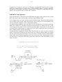
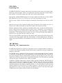
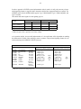
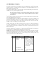
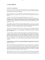
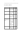
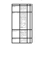
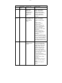
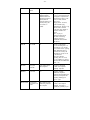
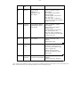
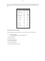
AT&T
MERLIN LEGEND™
COMMUNICATIONS SYSTEM
APPLICATION NOTES
MERLIN LEGEND™ COMMUNICATIONS SYSTEM
Applications Note On Basic Trunking Concepts
Abstract
This Application Note describes the various types of trunks that link the MERLIN LEGEND
Communications System with the telephone network. Operating characteristics of the various trunks are
shown to be a function of both the trunk type and the capabilities of the LEGEND system hardware and
software. The Note is designed to help Account Executives and System Consultants, so a basic approach
to the subject is used. The concepts covered also apply to other customer premises switching equipment as
well as the MERLIN LEGEND CS.
This Application Note is designed for use as a reference manual.
Refer to it each time you get involved with a MERLIN LEGEND system sale requiring a mixture of the
various types of lines and trunks.
MERLIN is a registered trademark of AT&T.
DIMENSION is registered trademarks of AT&T.
MERLIN LEGEND is a trademark of AT&T.
MERLIN MAIL is a trademark of AT&T.
MLX-10, MLX-10D, MLX-10L MLX-28D are trademarks of AT&T.
ACCULINK is a trademark of AT&T.
ACCUNET is a trademark of AT&T.
Copyright January 1992, AT&T
555-600-736
Issued January 1992
Copyright 1991. AT&T
555-600-736
Jim Pastorius
Kevin Lyons
Writers/Editors
Contributors:
A. Cohen
D. Guerro
V. Illuzzi
R.G. Koppenheffer
D. Margolis
S.W. Osborne
H.T. Reeve
M. Stevenson
B. Tannu
C.A. White
J. Webb
MERLIN LEGEND TRUNKING CONCEPTS
APPLICATION NOTE INDEX
Introduction
2
Tip & Ring Explained
2
Lines & Trunks
3
Loop-Start Trunks
Operations
Potential Problems
When to Use L/S
4
5
7
Ground-Start Trunks
Operations
Potential Problems
When to Use G/S
9
10
10
Direct Inward Dialing
Operations
Signaling Characteristics
LEGEND Operation
Administration
When to Use DID
11
12
13
13
15
TIE Trunk Operations
15
Tandem TIE Trunk Operations
16
Transferring Calls Over TIE Trunks
17
TIE Signaling and Implementation
17
Off-Premises Stations
19
T-1 (DS1) Service
21
Data Communications Equipment
23
DS1 Facility Services
26
Hotel/Motel Trunks
29
LEGEND Line/Trunk Hardware
30
Administration
35
Considerations
35
References
36
-2-
INTRODUCTION TO TRUNKING CONCEPTS
The way lines and trunks have been used to meet customers’ needs over past decades is rapidly changing.
T-1, ISDN technology, fiber optics, and other advances in telecommunications are forcing us to rethink
what lines and trunks should be used for a PBX or Key system. It is critical, however. that everyone
involved in giving customers the most advanced, yet economical. system have a basic understanding of the
concepts which are the foundations for sending and receiving telephone voice and data messages.
The goal of this Application Note is to explain the various types of lines and trunks which may connect to
the MERLIN LEGEND Communications System. The Note focuses on the concepts of each type of line
or trunk. While it also covers major interactions between the LEGEND system and the various
lines/trunks, it is not aimed at explaining everything needed to install, initialize. and maintain them on the
system. This is fully covered in the LEGEND System Installation, Programming, and Maintenance
Manual. Additional information on lines and trunks may be found in the LEGEND PBX and Key Systems
Planning Guides, as well as the Systems Reference Manual.
TIP AND RING EXPLAINED
The terms “Tip” and “Ring” occur inevitably in any description of telephone lines and trunks.
These terms originated in the early days of telephony when telephone connections were made by an
operator who inserted a plug into a jack. This plug was similar to the plug on a set of conventional stereo
headphones in that it had three conductors. These conductors were the “Tip,” corresponding to the tip of
the plug. the “Sleeve,” the longest Conductor at the base of the plug, and a ring of metal between the Tip
and the Sleeve called “Ring.”
The Sleeve was connected to a local electrical ground at the subscriber's premises and did not carry a signal
to the telephone company Central Office (CO). The Tip and Ring conductors each connected to a wire that
carried signals to the central office.
The terms became solidly embedded in telephone jargon and are still used in modem, electronic switching
even though the actual “tips” and “rings” have long since disappeared. Today the terms Tip and Ring are
used primarily as means for people in different places to identify precisely where each individual wire in
each pair of wires (in a huge bundle of wires) needs to be connected. When a pair of wires is reserved for
service as a trunk, one wire is designated Tip and the other wire is designated Ring.
During the process of ordering telephone service, a line assigner at the local operating company will reserve
a pair of wires for each line or trunk ordered. Each individual wire in the bundle is identified by a unique
color or combination of colors. Each trunk will have one color-coded wire assigned as the Tip lead and one
color-coded wire assigned as the Ring lead of that particular trunk. For instance, a cable might contain one
solid blue wire which would be reserved as the Ring lead on a given trunk, and one blue-and-white striped
wire which would be reserved as the corresponding Tip lead for that same trunk. The line assigner will
then furnish this information to installers at the customer’s premises and technicians in the central office.
In this way technicians can coordinate their installation work and make the proper connections between the
customer’s telephone equipment and the operating company’s central office.
-3-
LINES AND TRUNKS
Telephone lines and telephone trunks are facilities that carry voice or data communications. They are
similar in form and function, and the two terms are usually treated as if they are interchangeable. The
fundamental difference between a line and a trunk is that a line connects a station instrument to a switching
system, and a trunk connects one switching system to another switching system.
The connection between your home phone and the telephone company’s central office is a line. The
telephone facilities that serve key systems are also telephone lines, since a station in a mechanical key
system accesses a telephone facility by pressing the specific button that corresponds to the exact facility
desired. In a mechanical key system no switching takes place.
MERLIN LEGEND can be administered as a PBX, a telephone switching system that happens to be located
on a customer’s premises. A person using a LEGEND system telephone can access a wide variety of
facilities, none of which need to be permanently connected to that specific voice terminal, by dialing a code
(such as “9”) and having the PBX select one facility from a group, or pool, of facilities. The voice
connection from that station is then electronically switched to the selected facility.
Meanwhile, the facility that connects the voice terminal (station instrument) to the PBX is called a station
line. In this example the voice terminal corresponds to your home phone, and the Legend system represents
a scaled-down central office. Even though the station and the switching system are both in the same
building, a facility that connects a station instrument with a switching system is a line.
Most of the facilities that connect the LEGEND system to the local central office are properly called trunks,
but there are some misconceptions about this simple definition. Many PBXs, including MERLIN
LEGEND, support Personal Lines. These facilities typically appear on a voice terminal button and pass
transparently through the PBX, without being switched, to the central office. Selecting a personal line
button on a voice terminal and lifting the handset brings dial tone directly from the central office.
Historically, most telephone operating companies automatically engineered a trunk to better standards than
a line in a process called "conditioning." The central office equipment and the cable path used for trunks
had a meet higher standards for transmission quality than equipment used for line. Today most operating
companies are removing this provision from tariffs, and if a PBX requires conditioned trunks they will
probably be available on an extra-cost basis.
-4-
LOOP-START TRUNKS:
OPERATIONS
Loop-start facilities are the simplest and most common end-user facilities in the nation-wide telephone
network. Loop-start facilities provide virtually no supervision between the central office and the customer
premises equipment (CPE). For this reason, loop-start facilities are usually suited for use with telephone
systems that provide human supervision. Loop-start facilities are primarily intended for single line sets,
key systems with line status lights, or older PBXs. Loop-start facilities are generally not well suited for use
with PBXs that provide mechanical or electronic supervision.
A loop-start line or trunk consists of two wires running from the Central Office to the Customer Premises
Equipment (CPE). For historical reasons these wires are called Tip and Ring. (The term Ring, when
applied to one of the leads in a line or trunk facility, does not refer to the ringing signal sent to announce an
incoming call.) The CO applies battery voltage to the Ring lead and connects the Tip lead to ground.
These wires meet at a switch in the CPE that is normally open, and are bridged by ringing detection
equipment (such as the bell in a single line set) which provides a.high electrical resistance. 1
Telephone equipment on a loop-start facility signals the central office that it needs the facility for an”
outgoing call by closing this switch between the Tip and Ring leads. This may be as simple as lifting the
handset from the switchhook if the equipment is a single line set. When this switch is closed the resistance
between the 17p and Ring leads drops low enough to allow battery current to flow in a “loop” running from
the CO out to the CPE, and back to the CO. When the CO detects current flowing through the loop it
provides dial tone for an outgoing call.
The central office signals an incoming call on loop-start facilities by sending a ringing signal on the line.
These are the only two signals that are uniformly used by loop-start facilities.
It is important to note that these signals do not give advance warning of a change in switchhook state. The
only signal that the CPE sends to the central office that it is seizing a loop-start facility is the act of going
off-hook on that line. The signal from the central office that alerts the CPE to an incoming call is the
ringing signal received at the CPE at the same time or slightly after the call is connected to the facility.2
Also, it should be noted, there is no defined method for a central office to terminate a call, so there is no
reliable way to force a disconnect when only one of the two parties on a call hangs up.
1. Actually, the proper term here is impedance, not resistance, but the effect is the same for all practical purposes, no current flows.
2. See The Problem of Glare in the next section.
-5-
LOOP-START TRUNKS:
POTENTIAL-PROBLEMS
The most common application for loop-start facilities is single line residential service. Many of the
disadvantages of a loop-start trunk in a PBX environment can be inferred from the operation of a loop-start
residential telephone line, like the one you have at home.
The Problem of Glare
Perhaps, at least once in your life, you’ve picked up your home phone to make a call. only to hear a startled
voice saying “hello?” instead of dial tone. This is called glare. Glare is the most obvious problem
associated with loop-start facilities. This is due to the interaction of the extremely simple methods of
signaling that a line is being seized.
When a call for a given loop-start facility comes in to a central office it is connected to the proper facility,
and the signal from the central office ringing generators (90 volt, 20 cycle alternating current) is super
imposed onto it. The central office ringing generators provide the ringing signal in a cycle of two-secondson (ringing), and four-seconds-off (silence). ringing signal to start at the reception of each individual call,
so it is entirely possible for one call to be connected to a loop-start facility during the ringing period of the
ringing cycle, and the next call to be connected during the silent period of the ringing cycle. An incoming
call may be present on a loop-start facility for up to four seconds before ringing begins.
In a low traffic, single line, residential telephone situation this problem is uncommon, and sometimes it's
even amusing. Even though the connection is made without warning in a residential situation there are
only a few people that the incoming caller could be trying to reach. The problem, however, is more
noticeable with higher traffic, multiline key systems. But since most key systems are relatively small and
typically have close human supervision over line status and selection, these problems are usually identified
and resolved quickly.
With a PBX, such as MERLIN LEGEND CS, the problem of glare becomes more serious and comples.
Since ringing current is the only way that the central office can signal the PBX of an incoming call, and
since the PBX typically asssumes that a facility is available until it receives the first cycle of ringing current,
it's possible for the PBX to try to place an outgoing call on a loop-start trunk that has just been seized by
the central office and is carrying an incoming call. The PBX thus connects, without waring, two parties
who did not intend to reach each other.
A PBX trunk typically carries much higher levels of both incoming and outgoing traffic (more tails per
hour) than a residential telephone line, so glare is statistically more likely to occur on a PBX trunk.
Meanwhile, the ordinary station users on a PBX exercise little direct supervision over the individual trunks
in the system.
On the simplest LEGEND system, one without Automatic Route Selection (ARS), a station user would
typically lift the handset and hear dial tone from the PBX. The user would then dial an access code to a
trunk or group of trunks, and wait for dial tone from the CO. It is at this point that the user might suddenly
say “hello” to an unexpected incoming caller.
Features such as ARS magnify the problem. When the LEGEND system is administered for ARS the PBX
is a “slenderized” system. It holds the digits that are dialed, selects the appropriate trunk, and then goes offhook. LEGEND then waits two seconds on this trunk (under normal circumstances this is long enough to
obtain dial tone from the CO), and then dials the telephone number. Notice that LEGEND doesn’t actually
recognize dial tone, and it cannot recognize glare, it just waits two seconds and dials.
-6-
The ARS feature also isolates the station user from the specific trunk, and even the group of trunks. that
carries each outgoing call. Other features. such as Callback Queuing (LEGEND) or Busy-to-Idle (System
25) reminders, allow station users to seize trunks moments after a previous conversation concludes, and
easily fast enough to beat a ringing signal on an incoming call.
The glare problem can also be compounded if the PBX customer has terminals or computers that place
outgoing data calls without human supervision. If a terminal seizes a line for an outgoing call and
encounters glare it will probably disconnect (hanging up on the incoming caller), record a line failure. and
try again. The data user may become annoyed that a call attempt failed, but will never know about the rude
reception that was just given to a potential customer.
Automated Attendant Ghost Calls and Loop-Start Facilities
Several customers with loop-start facilities and the Automated Attendant have reported problems with
ghost calls. The human attendant who handles overflow calls from the Automated Attendant will notice
that often, when the phone rings there will be no one there. or occasionally the attendant will pick up the
ringing phone and hear dial tone.
The problem is caused by the fact that the Central Office does not send a reliable signal to force a
disconnect at the telephone terminal when only one party on a loop-start line call hangs up. Until the
second party hangs up, the loop-start line is considered in use by the CO, and can not be used to receive a
new call. This happens sometimes with ground-start trunks as well, since there is usually 20-40 seconds for
front end disconnect to pass through.
Consider the case of an automobile dealer that uses the Automated Attendant to direct calls to the new car
sales, used car sales, parts, and service departments. During the course of the day, the alder will receive
several calls from people who, for one reason or another, hang up while waiting for the Automated
Attendant.
Since there is no positive disconnect on loop-start facilities, (the CO does not signal the set to hangup), the
central office will continue to hold up the connection to the PBX. When this “connection” reaches the
Automated Attendant, the usual list of dial-selectable destinations will be recited, but since there is no
longer anyone on the call there will be no response. The Automated Attendant will time out and, in the
absence of a positive response, it will assume that it is dealing with a caller who has a rotary dial phone. It
will then forward the abandoned call to the human backup attendant. This person's phone will ring, but
there won't be anyone there. The condition can also give the perception that the caller was cutoff.
-7-
LOOP-START TRUNKS:
WHEN TO USE LOOP-START TRUNKS
There are two times when you consider the use of loop-start facilities: when you should use loop-start
facilities and when you must use loop-start facilities.
Proper Loop-Start Facility Applications
If loop-start facilities are prone to problems such as glare why are they still in use?
Most of the problems associated with loop-start facilities only come into play with automated PBXs.
Loop-start facilities are perfectly acceptable for use with single-line telephones, key systems, and manual
(cordboard or switchboard) attendant operated PBXS.3 Some PBXs, especially those that cannot be
administered by the customer, can operate properly with with loop-start facilities for one-way incoming and
one-way outgoing trunks, that must be handled by an attendant.
Besides, the cost of converting all of the loop-start customer and CO equipment currently installed to
ground-start operation would be an incremental expense.
Note: Loop-start trunks are not recommended for use with the MERLIN LEGEND configured for PBX
mode operation. Ground-start trunks are always preferred.
Unavoidable Loop-Start Facility Applications
One situation that will require the use of loop-start facilities on the LEGEND system would be the
connection of Centrex lines to the PBX. In some regions, Centrex is also called Essex or Centron lines.
Most operating companies will provide Centrex service only on loop-start facilities. Some operating
companies may consider converting the lines to ground-start facilities as an extra-cost special assembly, but
this is at the operating company’s option. Currently, the LEGEND system does not support the use of GS
Centrex.
Consider the case of a state government. In the early seventies the state linked all departments, large and
small, in one Centrex system in order to control inter-departmental message unit expenses. The individual
departments terminate their Centrex lines in large, non-uniform key systems.
Now, departments like Motor Vehicles and the State Police, have grown to the size of small companies and
occupy their own buildings. The Centrex is no longer capable of providing efficient internal
communications for the large departments, and traffic demands from large departments are swamping
service to smaller departments. The state would like to keep Centrex for convenient interdepartmental
calling without message unit charges. The larger departments, however, need PBXs like the LEGEND
system to take the load off the Centrex and for better internal communications. The local operating
company will only provide Centrex service on loop-start facilities. In this case, some loop-start Centrex
lines will terminate in the Legend system. Glare may occur on the Centrex lines. In general, ground-start
facilities are always preferred.
3. Some true manual PBXs are probably still present in the field. but you are not likely to encounter one during the installation of a
modern PBX. On a true manual PBX all calls, both incoming and outgoing, must be handled by an attendant. there is no way to
dial a code such as “9” for an outside line. h is this close supervision by the attendant that makes loop-start facilities acceptable for
use with manual PBXs.
-8-
Cost
Unfortunately, the most common reason for using loop-start trunks is the least valid. This reason is cost.
If a customer currently has a key system, service at that location is undoubtedly supplied by loop-start lines.
Converting the lines to ground-start trunks may involve a longer installation intend, and may incur
additional charges from the operating company. As a result, many loop-start lines are simply re-used as
loop-start trunks when the key system is replaced by a PBX.
However, if a MERLIN LEGEND CS is used, the customer has the flexibility of using either Loop Start or
Ground Start lines/trunks. This advantage not only eliminates out-of-service conditions, as would be
required if new replacement lines had to be installed, but can be a major cost-break by using the more
economical Loop Start Modules. Also, the combined GS/LS board is a key advantage of the LEGEND
system in facilitating the coordination with the telephone company in converting from LS to GS. It’s not
necessary to provide a loop-start module, and then have to replace it with a ground-start board should the
lines be converted.
-9-
GROUND-START TRUNKS:
OPERATIONS
Ground-start facilities were specifically introduced to solve the problems that PBXs encounter on loop-start
trunks. A ground-start facility provides an immediate signal when it is seized and it provides a positive
signal when one party disconnects.
When a ground-start facility is idle the CO provides battery voltage on the Ring lead, but the CPE does not
provide a ground on the Ring lead, and no current flows. Meanwhile, the CPE (LEGEND) monitors the Tip
lead for ground at the CO, but the CO does not provide a ground on the Tip lead when the trunk is idle.
When the CO needs to seize a facility for an incoming call it selects an idle trunk, makes sure that the CPE
has not applied ground to the Ring lead (no current is flowing), and the CO applies ground to the Tip lead.
The ground connection on the Tip lead completes an electrical path, current begins to flow, and the CPE
recognizes immediately that the facility has been seized for an incoming call. The CO also super imposes
the ringing generators onto the facility, but ringing may not occur at once.
The significant operational difference here is that, unlike the signal from the ringing generators, the ground
signal on the Tip lead is synchronized with the start of the incoming call. The CPE knows immediately that
the facility is not available for outgoing traffic, even if it does not begin to ring for several seconds.
Ground-start facilities also provide a positive indication of a disconnection. When the distant party goes
on-hook the CO removes battery from the Tip and Ring leads. Ground-start CPE (LEGEND) is designed to
recognize this disconnect signal and remove its party from the facility. (This prevents the party from
waiting for dial to to return, and prevent a toll restricted station from by-passing the restrictions.
Nearly all ground-start facilities are trunks, connecting PBXs with COs. There are only a few cases where
round-start lines might be encountered. Some pay phones, especially older ones, use ground-start lines to
obtain a positive disconnect signal and prevent a user from making multiple calls on a single coin. Also,
some unattended data equipment uses ground-start lines so the modem can determine when to start dialing
after going off-hook. Most modem equipment uses loop-start lines and alternate systems, such as a dialtone detector in the modem, instead of ground-start lines.
-10-
GROUND-START TRUNKS:
POTENTIAL PROBLEMS
There are very few problems that can occur when properly functioning ground-start trunks serve a properly
administered PBX, since modem PBXs and ground-start trunks were literally made for each other. This
Application Note does not cover the kinds of problems that can occur when a trunk develops a problem and
no longer functions properly. Suffice it to say that a malfunctioning ground-start trunk may behave just as
poorly as a malfunctioning loop-start trunk, but a properly functioning ground-start trunk will always
outperform a properly functioning loop-start trunk.
It’s possible that when a large key system customer upgrades to a PBX, the conversion from loop-start lines
to ground-start trunks may extend the installation interval. It is still always best to convert, and accept the
one-time inconvenience, in order to enjoy a much better grade of service over the long haul.
The most common installation problems involved with ground-start trunks are reversed Tip and Ring
connections and improper grounding of the PBX.
GROUND-START TRUNKS:
WHEN TO USE GROUND-START TRUNKS
Ground-start trunks should be used for a MERLIN LEGEND Communications System when configured as
a PBX.
They offer the following major benefits:
1.
The Tip ground seizure signal virtually eliminates the possibility that a two-way trunk can be seized
from both ends simultaneously.
2. The “window of opportunity” for glare is reduced from four seconds to a small fraction of a second.
3.
Ground-start operation also provides a positive indication of network disconnect when programmed
at the CO for Calling Party Control, allowing a PBX to disconnect a station when the outside party
on a call hangs up.
4.
The possibility of a user circumventing toll restrictions is eliminated.
-11-
DIRECT INWARD DIALING (DID) TRUNKS:
OPERATIONAL CHARACTERISTICS
Loop-start trunks and ground-start trunks are simple, two-way local facilities, i.e., they can handle
incoming and outgoing calls. The operation of loop-start and ground-start trunks can be understood by
analogy to the residential service in your your home.
Direct Inward Dialing (DID) trunks are different. DID trunks are not two-way trunks and cannot be
used for outgoing calls from the PBX, they are only used for incoming calls. Also, an individual DID
trunk is not associated on a one-to-one basis with a telephone number. Instead, a group of DID trunks is
associated with a block of telephone numbers, and any DID trunk in the group can carry an incoming call
directed to any DID number in the block.
DID trunks take advantage of the switching capabilities of both the PBX and the CO. The first step in an
installation involving DID service is to order a block of DID telephone numbers from the operating
company and the DID trunks that this group of numbers will serve. (Note: There will always be more DID
numbers than DID trunks.) This block is a list of sequential numbers that will route incoming calls to the
corresponding DID trunks. The minimum number of DID numbers that must be ordered varies from
operating company to operating company. Some companies require a minimum of 20 DID numbers per
block. Others may require as many as 100 numbers, and each DID number is billed to the customer.
When planning a DID setup, it should be kept in mind that generally each DID number corresponds to a
particular telephone station number or hunt group. The number 555-8743, for example, may correspond to
station 743, or to a Direct Call Group 555-7724 (Group code 724).
When the CO receives a call on a DID telephone number, it first identifies the block of telephone numbers
that includes this DID telephone number. It then determines the group of DID trunks that this block of DID
numbers has been administered to serve. The CO then selects one of these trunks and (in most cases)
checks to make sure the trunk is operating properly. If the trunk is not operating properly, the CO selects
the next available trunk in the same group and checks again. If no working trunks are available the CO
routes the incoming call to a reorder signal (a fast busy signal).
When an idle trunk has been selected, the CO signals the PBX that it has an incoming DID call. Then the
CO sends a series of pulses that identify the station that is intended to receive the call. (Note: In Controlled
Address Signal Outpulsing DID systems, described below, the CO signals the PBX that it has an incoming
DID call and waits for an acknowledgement from the PBX. When the PBX properly acknowledges the
signal the CO sends the addressing information and the call proceeds.) The addressing information is taken
from the network, and is based on the number that was actually dialed by the person who originated the
call. This permits each user to have exclusive use of a telephone number without requiring a dedicated
trunk.
-12-
Once a trunk has been seized -- the PBX has been alerted to the incoming DID call, and the addressing
information has been sent -- there are three possible responses from the PBX.
a. The PBX will return an audible ringing signal if the desired voice terminal is available, if the call can
be routed to a coverage position or attendant, or if the PBX can provide a recorded message (it will
still ring first before providing the message). The calling party will not be charged unless the call is
answered by a person or recorded message.
b. A busy signal is returned to the CO if the desired voice terminal is not available and the call cannot
be routed to a coverage position or attendant, or if all DID trunks are in use.
c. A reorder signal is returned to the CO if the PBX cannot complete the call due to inadequate or faulty
equipment, or if the PBX determines that the addressing information was incorrect or incomplete.
Calls to valid, but unassigned DID numbers, maybe routed to the PBX attendant.
DID Trunk Signaling Characteristics
The signaling associated with DID trunks is simplified a bit since DID trunks provide one-way incoming
service only. The generic name for the type of signaling used by DID trunks is called Loop ReverseBattery Signaling. The CO uses loop open (on-hook) and loop closed (off-hook) pulse signals to
communicate with the PBX, and the PBX uses reversals of battery and ground, which reverses the flow of
loop current on the Tip and Ring leads, to signal the CO.
The network controls whether current flows or doesn’t flow, and the CPE detects the pulses of current.4 The
CPE controls the direction of the current flow, and the network detects the changes, or reversals, of current
flow.
There are two different approaches to Loop Reverse-Battery Signaling: Immediate Address Signal
Outpulsing and Controlled Address Signal Outpulsing. There are two varieties of Controlled Address
Signal Outpulsing: Wink-start or Delay-dial.
Types of Loop Reverse-Battery Signaling
Immediate Address Signal Controlled Address Signal OutPulsing
Outpulsing
Wink-start
Delay-dial
Immediate Address Signal Outpulsing is the simplest method of providing DID service. It is the only
method used by the least sophisticated COs (DID-capable Step-by-Step Central Offices), and it may be
used by any CO if the available equipment requires it. With Immediate Address Signal Outpulsing, when
the CO must route an incoming DID call to the PBX it seizes a trunk by closing the loop and allowing
current to flow. Then it immediately begins sending the pulses that carry the call addressing information
without waiting for an acknowledgement signal from the PBX.
Controlled Address Signal OutPulsing provides better coordination between the CO and the PBX. When
the CO must route an incoming DID call to the PBX using one of the Controlled Address Signal
4. Notice that this is similar to the way that an analog voice terminal signals the PBX. When the voice terminal is on-hook (hung up)
no current flows and the station line is idle. When the voice terminal goes off-hook the switchhook doses the loop formed by the
Tip and Ring leads, current flows and the PBX prepares to accept a string of digits to dial for an external (or internal) call
destination. In the case of DID, the network closes the loop and the PBX prepares to accept a suing of digits for an internal call
destination.
-13-
Outpulsing methods, it seizes a trunk by closing the loop and allowing current to flow. When the PBX
recognizes the trunk seizure from the CO it responds by reversing the battery and ground on the Tip and
Ring leads. On delay-dial trunks this signal is called the delay-dial signal. On wink-start trunks this
reversal, going from an on-hook condition to an off-hook condition and back again, is very brief (140 to
290 milliseconds) and it is called the wink signal. This handshaking is called an integrity check.
If the CO does not receive a proper response it will not route its incoming call over that particular DID
trunk. In some wink-start systems the CO may be able to search for another available trunk and try to
complete the call again (this is called retrial). In other wink-start systems, and in all delay-dial systems,
retrial is not available. In these systems the incoming call will be routed to reorder tone at the CO and the
failure will be recorded at the CO as a trouble. If enough integrity failures are recorded against a DID trunk
it will be taken out of service by the operating company.
In general, the most efficient method for providing DID service is the wink-start type of Controlled Address
Signal Outpulsing, but the particular variety of Loop Reverse-Battery Signaling that will be used for any
given system is dictated by the capabilities of the CO, and will be decided by the operating company.
LEGEND OPERATION
Direct Inward Dialing calls ring on a System Access button (not “Line” buttons) on multibutton stations
and are eligible for call coverage, forwarding, following, etc. DID calls can also ring directly into singleline stations, DGC groups, or QCC Consoles.
The system is capable of accepting 1 to 4 address digits over the DID trunks, for each call, as administered
for each trunk group. The trunks are supported with the LEGEND system 800 DID module.
ADMINISTRATION
The use of DID trunks requires the following administration be completed:
●
Send calls for unassigned DID numbers to a specified endpoint (default is station 10). This number can
be a station extension, a DGC access code, or the Switched Loop LDN (main number). If no endpoint
is specified, reorder is returned to the call.
●
The following are administrable for a DID trunk group (maximum of 2 groups supported):
a. DID trunk protocol (Immediate Dial, Wink, default=Wink)
b. Dial Pulse (required) or Tone (desirable) (default=Dial Pulse)
c. Expected Number of digits (1-4, default=3)
d. Number of digits to delete (0 to 4 digits, default=0)
e. Digits to add (a number from 0 (none) to 9999: add 0 to 4, default=0)
●
The following are administrable on a trunk basis:
a. Alpha Character label (7 characters max.)
b. Trunk number (a unique flexible dial plan number, default in sequence
with other trunks).
c. Trunk Disconnect Timing (10 ms to 2550ms, default=500 ms)
DID numbers corresponding to pool dial-out codes (or facility access codes) can be used to avoid toll
restriction, leading to toll abuse or fraud.
-14-
The options for each trunk group are as follows:
* DID Trunk Protocol
*Wink start (default)
●
immediate start
* Dial Mode
* pulse (default)
●
tone
* Expected Number of Digits
* 3 (default)
*0 to 4
* Number of Digits to Add
* 0 (default)
* 0 to 4
CONSIDERATIONS IN USING DID TRUNKS
DID trunks are reliable and efficient, but they are more complex than loop-start or ground-start trunks. This
is why it is especially important to be aware of the way the individual components of a DID system
interact.
In particular, it is especially important to coordinate any MERLIN LEGEND system PBX installation and
maintenance work at the customer’s premises with the operating company. The PBX must be properly
administered for DID service, and the proper type of DID service, before the operating company puts the
trunk group into service. If DID trunks receive too many incoming calls while the PBX is “down” it is
possible that the network will record enough integrity failures to remove the DID trunks from service.
Callers to these trunks will receive reorder tone even after you’re sure you’ve returned the PBX to service.
In order to avoid this possibility, some telephone companies offer a busy-switch which is located at the
customer premises and connected to the CO. When testing is to be done, or the PBX powered down, the
switch can be used to alert the CO, and in turn, the CO will ensure the DID lines are not removed from
service.
Also, it is possible for the PBX to misinterpret the addressing information sent from the CO when the DID
trunk is seized. This is called digit mutilation. When this occurs, the PBX receives only part of the
addressing information. The LEGEND system will almost always recognize the mutilated digit sequence
as incomplete addressing information and return reorder tone to the CO. It is statistically possible for digit
mutilation to result in a valid, but incorrect DID code. If this happens the caller will get the wrong party.
And finally, DID service is efficient because it does not require a one-to-one correlation between a
telephone number and a trunk. In a properly sized system this enables more incoming traffic to be routed
over the DID trunks. However, if the system has been undersized (too few DID trunks to carry the traffic)
it will appear that incoming callers are getting busy signals while DID users are sitting idle. The busy
signals are actually reorder signals from the CO. The obvious solution to this problem is to install more
trunks.
-15-
WHEN TO USE DID TRUNKS
DID trunks provide fast access to specific individuals. DID trunks should be considered when a customer
has sales people who work with assigned territories, service people who work with ‘assigned accounts, or
any other organization seeking personal accountability. DID trunks, especially when combined with station
features like bridged appearances, combine the flexibility of key system operation with the sophisticated
options of the LEGEND system.
DID service is not available from all Central Offices, so always check availability before suggesting the
service to a customer. Remember that DID trunks provide incoming service only. For outgoing calls use
ground-start or WATS trunks.
TIE TRUNKS:
Simple Tie Trunk Operation
This application is perhaps the most common instance of the terms “trunk” and “line” being used
interchangeably. This type of facility links two PBXs.
In typical operation a user on the local PBX would like to speak to a station user at a remote PBX over a tie
trunk. The user on the local PBX lifts the handset to his telephone and gets dial tone from the local PBX.
The user dials the access code for the tie trunk, the local PBX connects the telephone to the tie trunk, and
the user on the local PBX hears dial tone from the remote PBX. The local station user then dials the
extension number of the remote user.
The switching capabilities of both PBXs are utilized in a call placed over tie facilities, so this facility is
.
properly called a “trunk.”
\fBSimple Tie Trunk Operation\fR
-16-
In special cases, tie trunks are used to join one PBX directly to another PBX. This may occur if multiple
PBXs serve a single-customer at a single location. A typical example would be a corporate headquarters
consisting of several buildings, each housing a separate division, co-located in a campus setting on a single
premises. This is sometimes called a “back-to-back” connection.
Tandem Tie Trunk Operation
In the case cited above, a station user on one PBX used the tie trunk to reach a station user on a second
PBX. This is basic tie trunk operation, and it is available on any LEGEND system.
A more advanced form of tie trunk operation is known as tandem trunking. This involves using a tie trunk
from one PBX to reach a trunk or other network facility. not just a station user, at a second PBX. Using
two or more facilities connected in series is called tandem operation.
In a tandem trunking operation a user on one PBX can access a facility that is not available on the local
PBX, but is available on a remote PBX. For instance, consider the case of a company with offices in New
York, Chicago, and Los Angeles. The New York office is linked with the Chicago office by a tie trunk, and
the Chicago office is linked with the Los Angeles office by a tie trunk. A station user in New York needs to
talk to an outside supplier in the Los Angeles area.
If tandem operation is supported at all of the PBXs, then the station user in New York can access the tie
trunk to Chicago and, from Chicago, access the tie trunk to Los Angeles. When the PBX at Los Angeles
has been accessed, the station user in New York can use a local, Los Angeles trunk to call the supplier.
(There will be some transmission degradation in this type of connection unless a digital network is used.)
Of course, these tie trunks can still be used to access other station users at the remote PBXs, just like
ordinary tie trunks.
\fBTandem Tie Trunk Operation\fR
Sta. B (New York) uses Tie Trunk
to access a local Los Angeles Trunk
-17-
TIE LINES:
Transferring Calls
The MERLIN LEGEND CS supports trunk calls that come into the system and go out on another trunk
without any operator assistance. However, the transmission code in the system does not permit multiple
hops, and there is no automatic routing system which can be used for tandem trunking.
Never-the-less, with the LEGEND system it is very easy to transfer your calls over a tie line to another
PBX. Whether the call you are on is a local line or a tie line call, the procedure is the same.
When you want to transfer a tie/local call begin by touching the Transfer button. This will give you dial
tone.
Dial the tie line access code to connect to another switch. (For the sake of this example, let’s say it’s a
Chicago switch.) When you hear dial tone, then dial the number of the extension in Chicago.
When the ringing tone is heard, complete the consultation transfer where you alert the called party that a
transfer is being made by remaining on the line until they answer. Alternatively, you can complete the
transfer by hanging up your station once the called station begins to ring; the transfer is completed
automatically y. If the called party does not answer after you’ve gone on-hook, then Transfer Return will
return the call to your station if the call is within your system.
If the user on the LEGEND system attempts to make another trunk-to-trunk transfer on the Chicago switch,
or to dial a local Chicago outside number, this would constitute a second or multiple hop. It is this type of
multiple hop the the LEGEND) system transmission code does not recognize, and the system does not
support.
.
TIE TRUNKS:
Signaling and Implementation
The PBXs that terminate the tie trunk must be optioned to work in a compatible manner (for instance, to
use tone or rotary dial pulse signaling), and the facilities must be engineered so they pass transparently
through any central office.
The LEGEND system is administered for the appropriate tie trunk operation when the smite is installed.
Tie trunks may use immediate start or wink-start operation, as described under DID trunks. Tie trunks may
also provide automatic operation. With automatic operation no start dial signals are used. The seizure
signal alone is sufficient to route the call to a predetermined destination. The call destination is determined
when the trunk group is administered, and is usually the attendant.
In addition, a signaling format must be specified. Unlike loop-start, ground-start, and DID trunks, tie
trunks may use special leads for signaling. These leads are called “E” (for “Ear”) and “M” (for “Mouth”),
and the system is referred to as “E&M lead signaling.” The “M” (Mouth) lead sends signals from the
switching equipment to the signaling equipment, and the “E” (Ear) lead listens for signals from the
signaling equipment and carries them to the switching equipment. A signal from the local system to the
distant system leaves on the “M” lead of the local system and arrives on the “E” lead of the remote system.
If E&M leads are not used the tie trunk is referred to as being “Simplex.”
-18-
In order to approach a.LEGEND system implementation with tie trunks it is really only necessary to know
which signaling formats are supported and to determine which of these supported formats are required. The
LEGEND system with the 400EM module supports Type 1 E&M Standard, Type 1 E&M Compatible, and
Type 5 tie trunks.
The transmit and control signals for each signaling type are:
TYPE
Type 1 Standard
Type 1 Compatible
Type 5
TRANSMIT
ON-HOOK OFF-HOOK
ground
battery
ground
open*/bat
ground
open
RECEIVE
ON-HOOK OFF-HOOK
open*/bat
ground
ground
open*/bat
open
ground
* Note: An open circuit is preferred over battery voltage.
AS its operation implies, the successful implementation of a tie trunk format will be dependent on matching
the characteristics of both of the switching systems it connects. The preferred signaling formats for a tie
trunk terminating in the MERLIN LEGEND system are:
FROM
TERMINATING SYSTEMS
DESCRIPTION
TO
LEGEND
LEGEND
LEGEND
LEGEND
LEGEND
LEGEND
LEGEND
LEGEND
LEGEND
S25/S75/Definity
S25/S75/Definity
S85
S85
Dimension
Dimension
OTHER
OTHER
LEGEND
LEGEND
MERLIN II
Co-located
Inter-office
Co-located
Inter-office
Co-located
Inter-office
Co-located
Inter-office
Same site
interbuilding
Same site
interbuilding
** Note: Plus a protection unit a little getting use to.
NEAR END
Protected/
MERLIN LEGEND
SIGNALING MODE Unprotected
Simplex Type 5
Simplex Type 5
Simplex Type 5
Simplex Type 5
E&M Type 1 Crept
Unprot
Type 1 Crept
Prot
E&M Type 1 Crept
Unprot
E&M Type 1 Crept
Prot
Simplex Type 5
Simplex Type 5
FAR END
Protected/
MERLIN LEGEND
SIGNALING MODE Unprotected
Simplex Type 5
Simplex Type 5
Simplex Type 5
Simplex Type 5 E&M Type 1 Std
Prot
Type 1 Std
Unprot
E&M Type 1 Std
**
E&M Type 1 Std
Simplex Type 5
Simplex Type 5
-19-
OFF PREMISES STATIONS
On occasion, customers need to locate telephones away from the principal area of the PBX or Key system
terminal concentration. The telephone can use an off-premises or out-of-building arrangement. There is a
major difference between the two types.
An off-premises telephone (OPT) is a single-line set that is located in another building and connected to the
LEGEND system via a special arrangement with the CO.
The station has the same features as an on-premises single-line station except it is counted
as an outside party in a conference call. Also, the message light feature will not operate
with the OPT set.
The OPT feature is sometimes used to provide service to executives at their homes. It allows them remote
access to the PBX system features and services.
An out-of-building telephone, on the other hand, is connected directly to a system port even though it is not
located in the same building. It may be an ATL or MLX set, single-line or multiline. Because it is direct, it
has access to all system features. However, if the telephone is located less than 1000 feet from the switch,
an IROB (in range, out of building) protector must be attached.
The OPT connection from a CO would be equivalent to a tie line; in effect, it is a dedicated line. Because it
has the same electrical properties as a tie line, the 008 OPT module can be used to connect the LEGEND
system to another LEGEND system, or another PBX or key system. The characteristics of the 008 OPT
module are listed below:
It should be noted that an OPT connection to a CO requires that the LEGEND system be no further than 1
to 3 miles from the CO, depending upon the characteristics of the CO involved.
008 OPT: The Off-Premises Telephone 008 OPT Module is used to connect off-premises touch-tone
telephones to the LEGEND system. The system software recognizes the 008 OPT module as a 012 module.
Even- though the OPT module has 8 jacks, it uses 12 ports of capacity, thereby decreasing overall station
capacity by four stations for every OPT module used.
Module
Station Type
Specifications
008 OPT
On-premises or
offpremises
single-line
telephone
Capacity: 8 stations, 2
Touch-Tone
receivers
Notice to Telco: meets
FCC 0L13C and :/FCC
Class C Loop resistance:
serves 2-wire loops to
1300 ohms, including
stations Port losses: 3 db
(both directions)
Unit Load Rating
8.0
max. distance supported
1-3 miles between Legend
and CO
-20-
When an Off-Premises telephone is connected to the LEGEND system via the 008 OPT module certain
accessories must be used for grounding and protecting the system from power surges, electromagnetic
interferences, and electrostatic discharges. These components are specified in Section 5 of the LEGEND
System Reference Manual.
Service technicians should be aware that the 008-OPT module is the same as the 008-DID module except
that the battery strap is in the On position for OPS, and in the Off position for DID. The factory presets the
strap and labels the module accordingly, based on the DOSS order.
The OPT trunk from the CO provides -48VDC on the tip/ring interface to the OPT station.
The MERLIN Off-premises Telephone lnterface (OPTI) (PEC 2302-OPI) cannot be used with the
LEGEND system.
-21-
T-1 (DS1) SERVICE
OVERVIEW AND OPERATIONS
The goal of the T-1 (DS1) section is to present basic information about T- 1 networking, what it is, how it
operates, and what it means to the customer. The section does not explain how the MERLIN LEGEND
Communications System interfaces with ISDN-PRI.
Further, this Note does not cover the indepth details of signaling and encoding on which T-1 service is
based. Instead the focus is on giving an overview of how T-1 fits into the telecommunications needs of
customers.
T-1 signifies a virtual revolution in how analog and digital signals are sent over a network.
It provides a two-way connection at 1,544,000 bits per second. This can be stated as 1.544 Megabits per
second (Mbs), which is also called “digital signal level one” (DS1). Generally the designation “T-1” means
any transmission line or connection running at 1.544 Mbit/s. In a stricter sense, T-1 is applied to the system
of copper wire cables and amplifiers or regenerators that reinforce the digital signal at intervals of
approximately one mile.
AT&T, telephone companies, and other interconnect companies all provide T-1 service. Also, a very large
customer may own its own T-1 system. A system can be made up of copper wire cables, microwave.
optical fiber, or other media. It is not unusual for three or more carriers using various media to be involved
in providing T- 1 service to a customer. Often it can be as many as six or eight carriers.
The standard T-1 line consists of 24 channels. One T-1 line replaces 24 of the voice grade analog copper
wire pairs known as 3002 lines. One T-1 can also transport 150 data channels; each would need a full voice
grade line on the analog network. To be most economical, T-1 transmission can combine voice and data
signals simultaneously.
If a customer connects to AT&T, the customer premises PBX must be compatible with a 4ESS (Generic 13
or higher) toll office switch. If the connection is to the telephone company, the PBX must be compatible
with the telco 5ESS central office switch. (The MERLIN LEGEND CS is certified for use with the AT&T
4ESS switch and the 5ESS switch for T-1 service.) It is possible to get fractional T-1 (FT1) service from
most T-1 providers where the user can designate time slots for sending and receiving by using only part of
the 24 circuits available in a T-1 link. The availability of FT1 will be of special interest to many GBS
customers. If customers have six or more circuits of any kind, fractional T-1 is likely to be more
economical.
To understand better the use of T-1 it’s necessary to appreciate the advantages that T-1 offers to the
communications system operator. These may be headed under the broad categories of Network Control,
Reliability, and Quality.
When telecommunications was solely dependent upon the use of voice grade 3002 lines, it was necessary to
know weeks (or even months) in advance when a user would require a change in the way network lines
were being used. It usually took that long for the telephone company to make the rearrangement. With T-1
service one of the major Network Controls the user gains is the quick ability to configure the system within
minutes. The network manager reassigns the channel resources where they are needed to meet changing
daily business requirements, emergencies, or to improve productivity.
Another Network control that is of vital user interest is diagnostic control. With the system split between
half a dozen carriers, it is necessary to be able to monitor the various parts on a continuing basis. This
means the user has the ability to locate faults and quickly get the proper maintenance group to restore
-22-
service, quickly and efficiently.
In the past it was necessary to establish a new circuit for virtually every application a customer wished to
use. Whether it was teleconferencing, facsimile, hifi audio, video, or computer transmissions, generally a
new line or trunk had to be run. It required a lot of time (perhaps months) and money to install each circuit.
With T-1 all these circuits can be simplified into a single T-1 circuit.
DESIGN, SIGNALING & IMPLEMENTATION
Design of a T-1 network can be focused on the public network, a private network (user owned), or a hybrid
combining advantages of both. Regardless of which is used, the MERLIN LEGEND Communications
System is ideal for connecting the customer to the T-1 service. It’s 100 DS1 Module allows connecting one
24-channel line to the PBX at a cost far less than that of connecting 24 voice grade lines to individual ports. .
In addition to the T-1 channels. the network requires the use of regenerators and multiplexer to boost the
signals and combine the information of the channels so it can be directed into a smaller number of channels.
The repeaters ensure high quality of the transmissions. The multiplexer allow more efficient and
productive use of the channels.
An advantage of T-1 is that it can send both voice and data over the same circuit.* This means the voice
signal must be converted to digital. A number of coding techniques are used to convert and compress the
analog voice signals into digital signals. AT&T uses a method called Pulse Code Modulation (PCM).
These encoding methods are what make it possible to transmit the traffic of 24 voice grade lines over one
T-1 line.
Before information can be sent over the channel it must be put into the proper format or frame. The
minimum need is that very 193rd bit be used to form a D4 or Extended Super Frame (ESF) pattern. This
minimum formatting will allow the customer to connect to any T-1 terminal device and route DS-1 circuits
through any carrier facility.
Further examination of the signaling and implementation required for T-1 circuits would warrant an indepth
technical presentation. The goal here is to show that T-1 can be of value to GBS customers.
Note, however, that T-1 service should not be the only dial tone available to a LEGEND system. It the
T-1 goes out of service the entire system would go down. This means that every T-1 system should also be
connected by ground-start trunks to the CO.
Potential Problems/Limitations
There are a number of factors, however, which could impede the implementation or T-1 service and should
be considered. They include:
●
The question of standards for all T-1 components is still unresolved. This means many manufacturers
of components are using proprietary interfaces and encoding methods. In turn this means the customer
is often forced to use the same equipment at both ends of a T-1 network.
4. MERLIN LEGEND Communication System requires ISDN-PRI to support digital data via the network.
-23-
The technology for T-1 is moving rapidly. The encoding system and components are not always
upgradable to the newer innovations.
●
If the customer application requires maximum network reliability, automatic dialing back-up in case of
digital facility failure could prove costly.
Do GBS Customers Need T-1?
Consider this: a standard T-1 circuit consists of 24 analog voice circuits. The cost of 24 long distance
circuits is more expensive than a T-1. Within the same Central Office a T-1 line is less expensive than the
use of 5-to-7 voice grade lines. This may also be true where only 2 voice grade lines are involved,
depending on the local traffic. Where fractional T-1 (FT1) is available, the cost break point is even more
favorable.
In fact, some GBS sized customers are losing money by not converting to T-1 service.
With a MERLIN LEGEND CS, a customer can use the T-1 lines as Loop-start, Ground-start or Tie (4-wire
E&M lines). This means the lines can be programmed to emulate, or look like, these facilities. (DID is also
available on T-1 service, but this is not supported on the LEGEND system.) When the 100D module is
programmed for T-1, it can be set to emulate which ever type of tine is needed (GS/LS/Tie - or OPX). The
programming must, however, match the settings for a given line assigned to it by the Central Office.
Complete details for administering the correct T-1 settings can be found in Section 4 (page 4-44), of the
LEGEND system Installation, Programming, and Maintenance Manual (555-410-140).
In order to use T-1 services the LEGEND system is connected to the network by a data communications
device called a Channel Service Unit (CSU). The next section explains the purpose of the CSU and the two
types available. It also covers the use of multiplexers used to increase the efficiency of the T-1 channels.
DATA COMMUNICATIONS EQUIPMENT
This section is an overview of various equipment which is used to enhance the capability of data
communications and or Integrated Services Digital Network- Primary Rate Interface (ISDN-PRI)
operations. The Channel Service Unit is necessary to connect the MERLIN LEGEND system to the Digital
Signal One (DS1) or PRI facility. The Multiplexer is designed for use on large systems where it is
necessary to combine the B channel input into a single digital stream for significant cost savings.
A hypothetical customer has installed a LEGEND system and is subscribing to MEGACOM service to
handle voice traffic. The question is, Which CSU should you order?
The LEGEND system will operate properly on either of the AT&T CSU's identified below. They both can
transmit up to 1.544 Mbps. While the Model 551-T1L1 is the lowest price unit, the ESF-T1 model
provides a more extensive range of features and diagnostic tools. The ESF-T1 should be the unit of choice
if the customer is capable of performing diagnostics on the circuits, and if the network smite will also be
used to transmit data. The 551 model should be used if the transmission speed is 56Kbps and clear
channels are not a primary concern.
-24-
CHANNEL SERVICE UNIT (CSU)
The Channel Service Unit (CSU) provides the interface between the 100D module and the DS1 facilities.
TWO AT&T models are available for use on the Legend system: the ESF T1 CSU and the 551 T1 L1 CSU.
●
Model 551-T1L1
Reg. Number G1 47226819-/DE-N
The 551 T1 CSU is a full-duplex modem, provides data terminal equipment (DTE) with
access to synchronous DS1, 1.544-Mbps lines. The CSU accepts data from the DTE
and transmits it to the serving central office. It also receives signals from the serving CO
and transmits them to the DTE. The CSU has three primary uses:
- To terminate a DS1 transmission system on a PBX
- To ensure that signals entering the public network from the DTE comply
with the transmission system’s requirements as defined in AT&T Technical
Reference 62411 and FCC Part 68 Requirements.
- To provide maintenance, diagnostic. and testing capabilities.
Model ESF-T1 Reg. Number GIC 47216544-DE-N
The ESF T1 CSU harnesses the real-time diagnostic capabilities inherent in facilities using
the Extended Superframe format (ESF), such as AT&T ACCUNET T1.5 Service. This
highly productive diagnostic tool evaluates circuit performance and records performance
data, without service interruptions. The ESF T1 transcodes DID through D4 formatted
signals into Extended Superframe format for transmission at 1.544 Mbps over T1 lines.
The Facility interface Codes for the CSUs are:
●
Digital D4 Framing 4DU9B
●
Digital ESF Framing 4DU9C
●
Digital ESF and B8ZS 4DU95
Note: If a non-AT&T CSU is used on a Legend system, AT&T will not accept the
responsibility for its installation, connection, or testing.
The ESF T1 CSU can connect the DS1 network by using the D4 or extended superframe format (ESF).
Also, it is the only CSU to provide the B8ZS line coding needed to transmit a 64-Kbps clear channel.
The ESF T1 CSU can be mounted in a relay rack or on a shelf as a stand-alone unit. Power can be provided
by plugging the CSU into a 117-VAC outlet.
Installation of the ESF T1 CSU involves setting the switch options. mounting the CSU as needed, and
connecting the wires from the l00D module and the DS1 network. The procedures for installing the CSU
can be found in Section 3 of the Legend Installation, programming and Maintenance Manual.
-25-
MULTIPLEXER (MUX)
Multiplexer are devices that combine several individual information-carrying channels for transmission
over an aggregate link. This is done by allotting this aggregate link to multiple users, in turn to constitute
different intermittent channels or time slots (time division multiplexing for digital transport.)
A Multiplexer in general would only be required for large PBX systems using multiple 100D DS1 Modules
where all B channels are assigned to various ISDN services. Customers would have complex voice/data
networks, have multiple locations, and usually a large investment in private line facilities.
AT&T ACCULINK Multiplexers, for example, can combine up to 128 input channels into a single digital
stream for cost-effective protocol-independent transmission. Each data ACCULINK channel can be
programmed individually for a wide variety of data rates, ranging from 300 bps to 64 Kbps. Special
application multiplexer, such as the ACCULINK 740 and 741, are designed to drop/insert data or video
channels from/to a DS1 data stream originating from a digital PBX such as System 25 or System
75/Generic while passing the remaining DS1 voice channels through to the digital PBX.
A special type of multiplexer which can be used on a MERLIN LEGEND system is an ACCULINK
Multiplexer. It would connect on the PRI side of the switch to the 100D DS1 Module. A 740/741 mux
provides preselected voice, data. or video signals to be added to or removed from the DS1. while allowing
the remaining DS1 voice channel to pass to the DS1 module. By the use of optional channel cards, a
740/741 can support up to 19.2 kbps asynchronous, or 56/64 kbps synchronous transmission.
-26-
The following table identities the AT&T DS1 services available to customers.
DS1 FACILITY SERVICES
Digital Signal 1 Service
Description
ISDN
T-1
Megacom (Megacom
WATS) Service
An
outgoing
domestic
longdistance service used
in place of WATS
service.
x
x
Megacom 800 Service
incoming,
An
toil-free,
domestic
number service for
voice calls
x
x
Megacom/Megacom
800 Service
Adding
Shared
Access for Switched
Service
(SASS)
allows Megacom and
Megacom
800
service on the same
trunks.
x
x
Megacom 800 Service
with Dialed Number
Identification Service
(DNIS)
An
incoming,
domestic
toll-free
number service that
voice
provides
information service
on an interactive
basis. Calls can be
routed to separate
or
departments
prerecorded
messages can be
played for different
groups of callers.
Multiquest Service
incoming
An
900
domestic
number service for
voice and data calls.
x
x
x
-27-
Digital Signal 1 Service
Description
Multiquest
With DNIS
Service
An incoming 900
number that provides
callers with voice
and data information
service on an
interactive basis.
software
Network
Service
Defined
(SDN)
A virtual private
networking service
for voice and circuit
switched data calls
(Up to 56 Kbps).
SDN lets businesses
use portions of the
AT&T
Switched
Network in concert
with their dedicated
private
line
networks.
The
system,
however,
does not support
“uniform
dialing
which is
plan,”
necessary
for
complete integration
with SDN.
x
ACCUNET Switched
Digital Service
A digital switching
service
between
subscriber
data
stations and far-end
connection. Useful
for batch data or file
transfer, high-speed
faxes, etc.
x
Data
LEGEND supports it
ISDN-PRI.
in
LEGEND does not
support it in straight
T-1.
x
Digital
Transmission
ISDN
T-1
x
x
-28-
Digital Signal 1 Service
Description
ISDN
Number
Station
Identification/
Number
Automatic
Identification
(SID/ANI) Service
caller
A
identification service
for systems with
display telephones,
call report systems,
etc.
x
** SID allows the
called
station to
display the station
number of the caller.
** ANI allows the
called
station to
display the billing
(main
number
telephone number) of
the caller.
subscribers can
choose to send their
calling
own
information to other
for
subscribers
display or suppress
the out- going caller
identification.
The
Note:
availability of the
caller identification
information may be
by
local
limited
conditions.
T-1
-29-
SPECIAL HOTEL/MOTEL TRUNKS
OPERATION OVERVIEW
In certain areas of the country there are special trunks for hotels and motels about which you should be
aware. At one time they were widely used but today they are found generally in rural areas. The trunks
generally are called HOBIC lines by telephone company personnel. The acronym stands for Hotel Billing
Information Center.
Actually, there is nothing different about the lines; it’s the service that’s different. The service is the Hotel
Billing Information System (HOBIS), which provides automatic time-and-charge information to the inn
each time a guest makes a call.
A similar service known as Centralized Charge Quotation Service (CCQS) provides the same information
for hospitals, law firms, advertising agencies, and other customers who need to keep accurate records.
A hotel/motel subscriber to the telephone company’s HOBIS service would be equipped with the trunks
and a special printer. A guest initiates an outside call over a HOBIC trunk by dialing a special entry code,
most often the number “8”. The HOBIS system immediately begins computing time and charges and relays
the information to the HOBIC center. When the call is completed, the center automatically sends a signal
over a data line to a modem which is connected to the printer. The printer lists the time and charges for the
call. This saves the motel operator or desk clerk from having to request the time/charge information for
each call. It also saves the hotel/motel dollars by allowing it to add the charges to the guests' room bill
before they checkout.
The AT&T Horizon PBX offered a special Hotel/Motel software feature package which used Hobic lines.
The feature package provided the software, modem, printer, and RJ11 line connector. Recently,
sophisticated optional accounting systems, such as CAS PLUS Hospitality Version available on the
MERLIN LEGEND Communications System have replaced the Hobic method, except in smaller, familyowned “mom-and-pop” type motels. These new systems do not use Hobic at all; they accumulate SMDR
data and calculate the price of each call based on rate tables included with the Call Accounting software.
MAINTENANCE AND TROUBLESHOOTING
Whenever installing or programming lines/trunks there can be problems encountered. This is a quick
reference guide to use when difficulty occurs.
When difficulties arise on the lines/trunks, consult the Maintenance section (page 5-39),
LEGEND Installation, Programming, and Maintenance Manual (IPM).
Also consult the Lines/Trunks Error codes/Solutions matrix in the Troubleshooting section
(page 5-46), in the IPM.
-30-
HARDWARE
The Legend system hardware most directly connected with Lines/Trunks are the Control Unit Modules.
The specifications for each module are presented later in this section. Also the system uses different types
of lines/trunks for the different individual functions of each operating mode. In PBX mode the system can
use the following:
●
Loop-Start (LS) trunks
●
Ground-Start (GS) trunks
●
Tie trunks
●
Direct Inward Dialing (DID) trunks
●
ADS 1 facility programmed for either T1 or ISDN-PRI operation.
●
Centrex Service lines - Loop Start*
A Key system can use:
●
Loop-Start lines
●
Tie Trunks
●
A DS1 facility programmed for either T1 or ISDN-PRI operation
●
Centrex Service lines - Loop Start
●
Ground start when registered as MF FCC classification.
A Behind Switch system can use:
●
Loop-Start lines
●
Tie Trunks
●
Centrex Service lines - Loop Start
●
A Ground-Start line when registered under the MF FCC classification.
●
Direct Inward Dialing lines
The LEGEND system with a basic carrier has five slots for these modules. Up to two expansion carriers
can be added, each one adding six slots, for an overall system total of 17 slots.
The system supports 13 types of line/trunk and station modules. The table on the next three pages identifies
the various modules and their uses.
4. For dial-tone only in PBX mode. Switchhook flash or pooled Centrex lines will not work to activate Centrex features.
-31-
MODULE
LEGEND SYSTEM CONTROL UNIT MODULES
SPECIFICATIONS
LINE/TRUNK
STATION TYPE
TYPE
008
n/a
Analog multiline
telephone; Call
Management System;
analog data with
a general purpose
adapter
008 MLX
n/a
MLX telephone; digital
data service (the
ISDN 7500B Data
Module)
Capacity: 8 digital stations,
each with 1 or 2 endpoints.
including the following station
types:
*digital voice only
*digital voice with Voice
Announce to Busy
*digital voice and digital data
(via ISDN 7500B Data Module)
*digital voice and MFM
*digital data only (ISDN 7500B
Data Module)
Signaling: ISDN-BRI S/T
protocol (2 64-kbps B channels,
one 16-kbps D channel), on a
passable bus.
Power: 48-VDC phantom power to
telephone: 48 VDC over a separate
pair (7-8) to an operator DSS console
Loop range: 1000 ft. in-building
and in-range out-of-building (with
MLX IROB protectors) service only
008 OPT
n/a
on-premises or offpremises single-line
telephone
Capacity 8 T/R stations on
2-way voice transmission path
with support for telephones with
message-waiting LEDs: 2 TTRs
Ringing current: 105-Vrms.
30-HZ sinusoidal ringing superimposed cm -48 VDC; a ring
generator must be installed in
the power supply module of each
carrier that has a 008 OPT module.
REN: <1.0 per port
.
Disconnect
signal: 900 ms
(T/R short for answering machines,
G3 Fax, etc.)
Switchhook flash detection
300-1200 ms
Loop Resistance: Serves 2-wire
loops to 1300 ohms, including
stations
Notice to Telco: Meets FCC
Class c
Capacity: 8 analog stations
Signaling: analog multiline
telephone protocol (40 kbps)
Loop range: 1000 ft in-building
or in-range out-of-building
with analog IROB protectors)
service only
- 32 -
MODULE
LINE/TRUNK
TYPE
STATION TYPE
SPECIFICATIONS
012 (T/R)
n/a
Single-line telephone;
MERLIN attendant;
MERLIN MAIL Voice
Messaging System T/R
adjunct (such as an
answering machine or fax
machine); analog data
device (such as a
modem)
Capacity: 12 T/R stations
on 2-way voice transmission path
with support for telephones with
message-waiting LEDs. 2 TTRs
Power: 21-VDC, 600-ohm
battery source
Ringing current: 105-Vrms,
30-Hz sinusoidal ringing
superimposed on -48 VDC; a ring
generator must be installed
in the power supply module of
each carrier that has a 012
module
REN: <1.0 per port
Disconnect signal: 900 ms
(T/R short for answering
machines, G3 Fax etc)
Switchhook flash detection:
300-1200 ms
100D DSI
T-1 or PRI
n/a
Capacity: 24 lines/trunks
for voice and analog data or 23
lines/trunks for voice and data
with 1 channel used for signaling.
Mode: multiplexes 24 or 23
line/trunks into 1 facility and
demultiplexes 1 facility into 23
or 24 lines/trunks
speed: Up to 64 kbps
Signalling: DS1 over 4-wire;
T-1 uses robbed-bit or common
channel; PRI has ISDN-PRI (23B + 1 D)
400/TTR*
Loop-start
and TTR
Power failure transfer
(PFT) telephone
Capacity: 4 lines/trunks.
4 TTRs. 1 PFT telephone
Signaling: Loop-start
400 E&M
Tie trunk
n/a
Capacity: 4 tie lines
Method of completion:
automatic start, immediate-start.
wink-start, or delay-did-start
Signaling: E&M type IS.
type 1C. type 5
400 GS/LS/TTR
Loop-start or
ground-start and
TTR
PFT telephone; button
needed for ground-sun
PFT telephone
Capacity: 4 lines/trunks,
4 TTRs, 1 PFT telephone
signaling: Loop-start or
ground-start, optioned per port
-33-
MODULE
LINE/TRUNK
TYPE
STATION TYPE
SPECIFICATIONS
408*
L00p-start
Analog multiline
telephone; Call
Management System;
PFT telephone
Capacity: 4 lines/trunks, 8 stations.
IPFT telephone
Station signaling: analog multiline
telephone (40 kbps)
Line/trunk signaling: Loop-start line/
trunk: analog voice
Loop range: 1000 ft.. in-building and
in-range out-of-building (with analog IROB
protectors) servicc only
408 GS/LS
Loop-start or
ground-start
Analog multiline telephone;
Call Managemcnt System:
PFT telephone
Capacity: 4 lines/trunks, 8 stations.
1 PFT telephone
Station signaling: analog multilinc
telephone (40 kbps)
Line/trunk signaling: Loop-start line/
trunk (optional per port): voice
Loop range: 1000 ft. in-building and
in-range out-of-building (with analog IROB
protectors) service only
800*
Loop-start
PFT telephone
Capacity: 8 lines/trunks, 2 PFT
telephones
Signaling:R loop-start
800 DID
Direct Inward
Dialing
n/a
Capacity: 8 trunks. 2 TTRs
Transmission: incoming calls only;
2-way (l-pair) fixed impedance to DID
trunks; no outgoing calls
Signaling loop-reverse battery;
wink-start or immediate start; accepts
touch-tone dialing
800 GS/LS
Loop-start or
ground-start
PFT telephone; button
needed for Ground-start PFR
..
Capacity: 8 lines/trunks. 2 PFT
telephones
Signaling Loop-start or ground-start
* Note: Although these MERLIN II module are supported in the MERLIN LEGEND Communications System. the 400 GS/LS. 408
GS/LS. and the 800 GS/LS are the recommended modules for use in the LEGEND system.
-34-
This section lists the LEGEND system trunk and off-premises modules and the appropriate PEC and
Comcodes. More complete code information can be found in Section A of the Systems Manual (555 -610200).
Line/Station Modules
PEC
Comcode
100D DS1 module
61491
105461560
400 E&M module
8303-200
105311401
400 GS/LS/TTR module
61483
105627988
400 (TTR)
408 LS ATL module
61379
105408892
61482
105512495
408 GS/LS ATL module
61481
106064678
800 DID module
61488
105628002
800 GS/LS module
61484
105627996
800 LS module
61384
105351100
008 OPT module
61489
106387525
008 ATL module
61485
105351092
008 MLX module
61486
105628010
012 Basic Tel
61487
106397631
Reusable Modules from Merlin II (R3)
The following modules used in Merlin II Release 3 system can also be used in the Legend system.
●
391A Power supply module
(39lA1 recommended; found in later MERLIN II R3s)
●
800 Line/trunk module
●
400 Line/trunk module
●
400 E&M line/trunk module
●
012 Basic telephone module
●
008 Analog station module
●
408 Analog line/trunk & station module
-35-
ADMINISTRATION
To properly administer a MERLIN LEGEND system at the time of initialization requires that care be taken
during the planning phase of the sales activity. This is especially true if the system is to connect to a
number of different trunks and lines, such as DID, Tie, or ISDN. in addition to using local CO Loop-start
and Ground-start lines. To assist in the planning of the system, sample, filled-in copies of the
planning/administration forms are available. They can be found in the LEGEND PBX System Planning
Manual (555-610-113), and the Key System Planning Manual (555-610- 112). These forms should be
reviewed before starting to complete an actual set of forms for customers’ systems.
Also, keep in mind, that any MERLIN LEGEND CS configuration that requires the use of T-1 and/or PRI
trunks, must be reviewed by the NSAC. The Planning Manuals contain directions for sending the
appropriate forms to the NSAC.
CONSIDERATIONS
Special care must be taken when planning and ordering trunks and lines for the MERLIN LEGEND CS.
The most important aspect which the planner must keep in mind is that it is critical to investigate what
services the local interconnect company can provide. For example, if a Behind Switch system is to be
connected to a telephone company Centrex switch, the Central Office must be able to provide Loop Start
lines capable of sending a disconnect signal. Otherwise the Legend system will ultimately hangup as more
and more trunks are considered in use because no disconnect signal was received by the system.
Also, keep in mind that the use of Ground Start Centrex lines are not supported by the LEGEND system.
So ensure that the CO does not include any GS lines in the block of Centrex lines it assigns to the Legend
system.
-
When consulting with the Central Office regarding Lines and Trunks, also determine the proper timer
setting for the disconnect signal from the CO.
When ISDN applications are being considered, the networking should be through an AT&T 4ESS switch
(Generic 13 or higher), operated by Network Systems in order for the customer to obtain the largest
selection of ISDN services. However, the MERLIN LEGEND Communications System also will operate
properly when connected to a telephone company 5ESS switch.
-36-
REFERENCES
GBS SCAN Competitive Newsletter, “Everything You Need to Know About ISDN”, Nov/Dec 1988.
MERLIN LEGEND Key System Planning Manual (555-610-112)
MERLIN LEGEND PBX System Planning Manual (555-610-113)
MERLIN LEGEND Data Guide (555-610- 114), Chapter 2
MERLIN LEGEND System Reference Manual (555-610-110)
MERLIN LEGEND Installation, Programming, and Maintenance Manual (555-610-140)
AT&T ESF T-1 Channel Service Unit User’s Manual (999-100-305), 1988.
Lescinsky, F.W.; FDS ISDN PRI Digital Data, Iss. 1.1; 8/13/91
Wright, A.E.; FDS ISDN PRI Service, Iss. 1.0; 2/13/90
PM.4