1
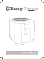
OWNER’S Manual
PRINTED IN CANADA
10/2009
Table of contents
Introduction
2
General Safety Instructions
4
Installation Instructions
Location
6
Water piping
7
Electrical
7
Bonding
8
Bonding and plumbing step-by-step instructions
8
Using an External Controller
10
Electrical Connections
11
Wiring Diagram
12
Service Analyzer Control
13
Operation
14
Caring for your Pool Heater
15
Initial Startup
16
Meaning of Display Codes
17
Troubleshooting
18
Requesting Assistance or Service
20
Maintenance
21
Winterizing
21
Hayward® Heat Pump Pool Heater Limited Warranty
22
International Warranty
23
Notes
24
Warranty Card Registration
25
OWNER’S MANUAL
Thank you for buying
an EASY TEMP pool heat pump.
The EASY TEMP pool heat pump is a self-contained unit designed specifically
for pool heating. Each component has been selected with care to achieve a
high-quality product in an effort to exceed all industry standards.
All EASY TEMP pool heat pumps have an electronic board with service
analyzer, a titanium heat exchanger tube warranted for 10 years against
corrosion and a UV-resistant plastic cabinet that eliminates all maintenance
for life. All components are of superior quality, which presents you with an
effective, state-of-the-art technology heat pump.
Compared to other types of pool heaters, such as gas or oil-fired, the
EASY TEMP pool heat pump has a lower heating capacity on a BTU/hr
basis. Therefore, it needs to operate for a longer time to accomplish the
desired results. Occasionally, it may be necessary to run the heat pump for
up to 24 hours per day. However, this should not be of concern to the owner
because the heater is designed to operate continuously. What’s more, despite
continuous operation, it will still heat the pool far more economically than other
types of heaters.
As with all pool heaters, you are advised to use a pool cover at night and when
the pool is not in use. The pool cover should be used if night temperatures are
15°F less than desired pool temperature. This will keep evaporation, the greatest
source of heat loss, to a minimum, thus greatly reducing the overall pool heating
costs. During warmer weather, the pool cover may not be required.
2
OWNER’S MANUAL
Please read carefully
Record your model’s information
Please complete and mail in the ownership registration card provided with
this guide. The return address is displayed on the front of your registration
card. Simply mail it as you would a postcard. The card helps us notify you
about any new information about your heater.
Whenever you call to request service for your heater, you must know your
complete model and serial numbers. You can find this information on the
plate located at the base of your heater.
Please also record the purchase date of your device and your dealer’s name,
address, and telephone number.
Model Number ____________________________________________________
Serial Number _____________________________________________________
Purchase Date ____________________________________________________
Dealer Name ______________________________________________________
Dealer Address ____________________________________________________
Dealer Phone _____________________________________________________
Keep this book and the sales slip together in a safe place for future reference.
Service can now be obtained by calling
these phone numbers.
CANADA: 1 888 238-7665
USA: 1 908 355-7995
OWNER’S MANUAL
3
General Safety Instructions
We care for our customers
We have provided important safety messages in this manual and on your
heater. Always read and obey all safety messages.
?
IMPORTANT
The IMPORTANT sign calls attention to a note that provides important
information or information essential to the completion of a task.
CAUTION
The CAUTION sign denotes a hazard. It calls attention to an operating
procedure, practice, or the like, which, if not correctly performed or
adhered to, could result in material damage, particularly to the product,
up to the destruction of part or all of the product.
!
WARNING
The WARNING sign denotes a hazard. It calls attention to a procedure,
practice, or the like, which, if not correctly performed or adhered to,
could result in personal injury or injury to a third party. These signs are
rare, but are extremely important.
4
OWNER’S MANUAL
CAUTION
!
!
All electrical connections must be done by a qualified electrician and
according to the local electrical codes. Always cut off the unit’s main
power whenever the access panel is open or removed. Always install the
machine outdoors (unless otherwise approved by the manufacturer),
while respecting the minimal clearances needed for proper operation
and heating.
CAUTION
Proper pool chemistry is vital to the life of your heater. Pay particular
attention to the total alkalinity and TDS. It is highly recommended that you
have your pool chemistry checked often by an independent pool store.
OWNER’S MANUAL
5
Installation Instructions
Location
The placement of the pool heater is very important in keeping installation
costs to a minimum while providing for maximum efficiency of operation, as
well as allowing adequate access for service and maintenance.
The pool heat pump is designed for outdoor installation and should
not be installed in a fully enclosed area, such as a shed, garage, etc.
Recirculation of cold discharged air back into the evaporator coil will greatly
reduce unit heating capacity and efficiency.
The unit should be located as close as practical to the existing pool pump and
filter to minimize water piping. However, do not forget to provide a 24”clearance at the very least all around your heat pump. The use of 90 degree bends
and short radius elbows in the water piping should be kept to a minimum.
Mount the unit on a sturdy base, preferably a concrete slab or a set of blocks.
The base should be completely isolated from the building foundation wall to
prevent the possibility of sound or vibration transmission into the building.
The size of the base should not be less than 36” x 36” (92 cm x 92 cm).
? IMPORTANT
Air is pulled through the evaporator coil and
discharged through the top grille. A minimum
clearance of 72 inches should be allowed above
the unit for unrestricted air discharge. The unit
must not be installed under a porch. Any side of
the unit should be located at least 24 inches from a
wall or from any other obstruction for unrestricted
air intake and service access.
24”
72”
24”
24”
Service access
24” to 36”
6
OWNER’S MANUAL
Water piping
? IMPORTANT
The piping sequence is as follows: pool > pool pump > filter > heater > check
valve > chemical feeder > pool. Automated chlorine distribution systems, if
used, must be placed downstream of the heater to minimize harm to the pool
equipment. Use rigid PVC piping if possible (SCH40 or SCH80). All joints
should be glued with PVC glue. When the piping installation is complete,
operate the pool pump and check the system for leaks. Then, check the filter
pressure gauge to verify that there isn’t any indication of excessive pump
head pressure.
You can also make the connections using high-pressure flexible hose, but
make sure the hose can withstand high pressure. The installation of a heat
pump bypass is not necessary unless the water flow exceeds 75 GPM.
Note: Certain installations have valves which isolate the heat pump from the water circuit. If the heat exchanger
is deprived of water circulation for several days, high chlorine gas could cause excessive corrosion. If the disconnect
switch is turned off, be sure that the pool water is allowed to circulate through the unit, or is drained out of it.
Electrical
! CAUTION
The wiring of your pool heat pump should be performed by a qualified
electrician in accordance with local requirements.
A properly-sized breaker and copper wire must be used.
Check the heat pump data label for required maximum breaker size.
WARNING
The unit must always be powered off before opening the access panel.
OWNER’S MANUAL
7
Bonding
! CAUTION
Because all metals have different electrical potentials, all metal and electrical
components of the pool system must be bonded together. This includes the
metal framework of the pool, the light, the pump, the filter (if made out of metal),
the heater, any automatic chlorine generator, and any other metal or electrical
equipment. On some older pools, this substructure bond wire may not exist.
In these cases, a 6 to 8 foot solid copper rod must be driven into the ground
near the equipment. All electric and metal components must then be bonded
to each other, and then to the copper rod.
Bonding and Plumbing
step-by-step instructions
1. A 1/3 lb check valve must be installed between
the heater and any automatic chlorine distribution
system (if used).
2. Any kind of automatic chlorine distribution system
must be installed after or downstream of the heat
pump.
3. The filter must be placed before or upstream from
the heat pump.
4. A bypass and shut-off should be installed on
all systems for ease of service, maintenance and to
balance the water flow. Bypasses must be installed
on any system with over a 3/4 HP pool pump.
(see FIG.3 for bypass plumbing)
8
OWNER’S MANUAL
Bonding and Plumbing diagram
Fig. 2
Chemical
feeder
Heat Pump
Fig. 3
OWNER’S MANUAL
9
Using an External Controller
To connect the electronic board in order to control it remotely, use the P_S
terminals on the right side of the board. Next, access the P_S menu and select the desired mode. In internal mode, POOL or SPA mode can be adjusted
by using this menu. In external mode, a normally open contact puts the board
in POOL mode and a closed contact puts the board in SPA mode. Therefore,
a board set to OFF in POOL mode and to 80 degrees in SPA mode can be
controlled with an external switch to heat up to 80 degrees.
Internal mode: Use the P_S mode on the main menu
External mode: • Open contact = POOL mode
• Closed contact = SPA mode
Control using a switch
To control the board using an external switch, follow these steps :
• Turn on the heat pump.
• Set POOL mode to OFF.
• Set SPA mode to the desired temperature.
• Access the setup menu.
• Select mode E (external) on the P_S menu.
• Run two J7 (P_S) terminal wires from the HPEC-003 board to the NO
switch terminals (see FIG. 4).
• You can now control the operating mode by turning off the switch
(open = POOL, closed = SPA.)
Fig. 4
External switch
Pool (open)
Spa (closed)
10
OWNER’S MANUAL
Electrical Connections
WARNING
The installation of the pool heater should be performed by a certified
electrician. To connect the electricity, you must unscrew the five screws of
the front panel, then slide the electric cable through the knock out located
on the left or the right side of the base, and then insert it in the control box.
The electrical diagram is located on the lid of the control box as well as in
this manual.
Fig. 5
Power requirements
240 V, 1 PH, 60 Hz
Look at the name plate located on the heat pump to know
the required amperage.
Please refer to your local
electrical code for additional
wiring requirements.
L1
L2
Ground
OWNER’S MANUAL
11
12
OWNER’S MANUAL
Flow switch
Closed = flow
Opened = no flow
Low pressure switch
Closed = OK
Opened = low pressure
High pressure switch
Closed = OK
Opened = high pressure
Defrost sensor
Water sensor
LP
LP
FLO
FLO
COMPRESSOR
HGD
H/C
24 VAC
Yellow
P S
Yellow
Yellow
FAN
Purple
Purple
Light Blue
Light Blue
Red
Brown
CAP
24 Vac
R
S
1 Phase
208 / 230 Vac, 60 Hz
Orange (240 Vac)
or
Red (208 Vac)
Remote switch
Pool (opened)
Spa (closed)
Black
Blue
HP
FAN
24 Vac transformer
HP
COMPRESSOR
Black
DS
FAN
Black
WS
HPEC-003
Control Board
Black
Brown
Brown
L2
L1
24 Vac compressor
contactor
COMPRESSOR
Ground
C
CAP
Wiring Diagram
Service Analyzer Control
The control panel is factory set to display the temperature in Fahrenheit degrees.
Celsius or
Fahrenheit mode
Heating mode
Compressor ( )
or fan ( ) running
Temperature
and parameter
display
Heating mode
To raise the desired
temperature or to
change parameters
Access to
parameters
To lower the desired
temperature or to
change parameters
OWNER’S MANUAL
13
Operation
To increase the temperature
Push the SET key until you see POL or SPA. The programmed temperature
will be displayed. Press the UP arrow
to increase the temperature setting
one degree at a time.
To lower the temperature
Proceed as explained above using the down arrow
.
To select the pool or spa mode
The unit can keep two temperature settings in memory: one for pool mode
(max: 95°F/35°C), and the other for spa mode (max: 104°F/40°C). To have
access to either program, press the SET key until you see P_S and by pressing one of the arrow keys, you can switch to POL or SPA. Once the heating
mode has been programmed, it will be displayed for five seconds, and will
then return to the actual pool water temperature. The lights on the right side
of the display indicate the chosen heating mode.
To display the temperature in °F or in °C
Press the SET key until you see F_C and by pressing one of the arrow keys,
you can switch to °F or °C. Once the tempurature unit has been programmed,
it will be displayed for five seconds, and will then return to the actual pool
water temperature in the mode that you have chosen.
14
OWNER’S MANUAL
Caring for your Pool Heater
How to protect your pool heater
OWNER’S MANUAL
15
Initial Startup
? IMPORTANT
Before starting the pool heater for the first time, it is important to verify that
the breaker is in the ON position.
Also make sure that the water circulates freely and that the pool pump is activited.
Then, you will need to set the water temperature you desire. The fan will
immediately start. The compressor will start after a 3 to 4-minute delay.
When the compressor is running, the HEATING/CHAUFFAGE indicator located
on the right (see “Service Analyzer Control,” p. 13) should be lit. At initial startup,
it is normal for the unit to run 24 hours a day.
It is also normal to see water dripping from the holes at the base of the unit.
This is just condensation.
16
OWNER’S MANUAL
Meaning of Display Codes
Service Analyzer Codes
Most problems will be detected by the service analyzer and a code will be
displayed on the digital display of your heater.
Display Meaning of codes
OFF
The desired programmed temperature point is lower than 60°F
(15°C).
LP & LP3
Shortage of refrigerant gas in the unit or faulty low pressure
control. The digital display will show LP3 after 3 LP faults and shut
down your pool heater. The pool pump will also be stopped for protection if the unit’s internal time clock feature is used. If LP or LP3
occurs you should call for service.
HP & HP3
Low water flow to the unit or faulty high pressure control. Check water flow. Backwash filter and/or heater. The unit will show HP3 after
3 HP faults. This will stop your heater for protection.
Po
Water temperature probe connected to WS on the electronic
board may be disconnected. If it is not, the probe may be open or
defective.
Pc
Water temperature probe is short circuited or may be defective.
FLo
Possible causes:
- The filter is in backwash position.
- The filter pump is stopped.
- The filter is dirty.
- Shortage of water to pool pump.
- Water pressure switch must be adjusted or it is broken.
dPo
Suction temperature probe connected to DS on the electronic
board may be disconnected. If it is not, the probe may be open or
defective.
dPc
Suction temperature probe is short circuited or may be defective.
FS
Unit currently in defrosting cycle (the fan works but the compressor
is stopped). This is normal operation when outside temperatures
are cold.
OWNER’S MANUAL
17
Troubleshooting
The pool heater is not running.
Heat pump control set to OFF.
Raise temperature set point above
60°F (15°C).
Desired water temperature
is reached.
Unit will automatically restart
when the water temperature goes
below the set point.
Main breaker is tripped.
Reset main breaker and restart
heat pump.
The heater is displaying “flo” and it will not start.
Pool pump is not running.
Turn the pool pump on.
Filter is dirty, restricting
the water flow.
Backwash and clean filter.
The fan is running, but the compressor is not.
The heat pump is in protection
mode.
In this case, there may be
a 5-minute delay before
restarting.
The unit is on defrost
cycle.
Digital display should indicate FS.
The compressor will automatically
start again a few minutes after the
display stops indicating FS.
18
OWNER’S MANUAL
There is no display and the fan is not running,
but the compressor is running.
Ask your electrician to verify your heat pump’s power supply by
checking over the L1 and L2 connections in the unit’s service box.
There is water around the unit.
While your pool heater is in the
heating mode, a large quantity
of warm and humid air passes
over the evaporator and causes
condensation. It is normal to see
condensation dripping under
the heater.
To check if the water really is a
leak, you must stop the heater
and leave the pool pump running
for over 5 hours. If water is still
coming out of your heater after
this period, then call your dealer
for service.
The heater is running but desired water
temperature cannot be reached.
Heat loss is too much for the heater; cover your pool as often as
you can.
Evaporator is dirty.
Clean it by running tap water over
the coil without additional nozzel
attachment. Do not use pressurized water as it can damage
the coil and void warranty.
Evaporator restricted due to improper location (see “Location”,
p.6).
Restricted water flow.
Adjust water flow.
Note: If your pool heater does not operate for reasons other than those mentioned above, please contact Consumer
Assistance Center (see “Introduction”, p. 3) to obtain the proper authorization for the warranty to apply.
OWNER’S MANUAL
19
Requesting Assistance or Service
? IMPORTANT
All service will be handled by an Authorized Service Center. Warranty may be
voided if service is not done by an Authorized Service Representative. Do not
return the heater to your dealer as they do not provide service.
Before calling for assistance or service, please check the “Troubleshooting”
(pp. 18-19) and “Warranty” (pp. 22-23) sections or call your dealer. It may
save you the cost of a service call. If you still need help, follow the instructions below.
Service can be obtained by calling one of these phone numbers.
CANADA: 1 888 238-7665
USA: 1 908 355-7995
When asking for help, please provide a detailed description of the problem,
your heater’s complete model and serial number, and the purchase date
(see p. 3). This information will help us respond properly to your request.
Keep a copy of the sales receipt showing the date of purchase. Proof of
purchase will assure you warranty service.
20
OWNER’S MANUAL
Maintenance
Dirt can accumulate on the evaporator. You can easily remove it by using
a non-pressured water spray without damaging the small aluminum fins.
The cleaning of the plastic cabinet can be done with the help of a brush and soap.
Winterizing
First, you must turn the breaker off. The unit must be drained of all its water.
You will need to disconnect the IN and OUT water connections. Then the unit
must be tilted or blown out with air until all water is out.
The next step is to reconnect your IN and OUT water connections that will
have previously been drained.
It is recommended to cover the heat pump to prevent snow from getting
inside. A protective winter cover is also offered by your retailer.
OWNER’S MANUAL
21
Hayward® Heat Pump Pool Heater
Limited Warranty
The HAYWARD heat pump pool heater is warranted to be free of defects in
materials and workmanship for a period of two (2) years for parts and (1) one
year for labor. In the state of Florida, warranty labor is covered for (2) years.
This warranty is applicable to the original location and owner only and is not
transferable. The compressor component has a five (5) year limited warranty
with parts and labor warranted the first two (2) years and parts only warranted
in years three (3), four (4) and five (5). The titanium tube component of the heat
exchanger has a ten (10) year warranty. HAYWARD will not void this warranty
due to improper pool chemistry. This warranty is valid only if the product is
installed according to the HAYWARD specifications.
This warranty does not include refrigerant or other expendable materials, or
services such as inspection, maintenance, or unnecessary service calls due to
erroneous operational reports, external valve position, or electrical service. It
also does not include the repair of damage due to negligence, accident, freezing, installation in corrosive environments or atmospheres, conditions beyond
the normal intended use of the unit, or acts of God. This warranty is void if the
product is repaired or altered in any way by any persons or agencies other than
those authorized by HAYWARD, and is in lieu of all other warranties, expressed
or implied, written or oral. There are no implied warranties of merchantability or
fitness for a particular purpose that apply to this product. This warranty applies
to the continental USA, Hawaii, Alaska and Canada. For warranty outside these
locations please visit www.haywardnet.com.
At its option, HAYWARD will replace or repair any HAYWARD part that proves
defective if such parts are returned to our factory, freight collect, within the
warranty period. It is agreed that such replacement or repair is the exclusive
remedy available from HAYWARD. Unless authorized by HAYWARD and performed by a factory authorized service center, HAYWARD is not liable for any
labor involved in the removal of defective parts or the installation of replacement parts. HAYWARD is not liable for damages of any sort whatsoever, including incidental and consequential damages. Parts returned and services performed under terms of this warranty must be approved by HAYWARD. All parts
returned under terms of this warranty will be repaired or replaced and returned
transportation charges prepaid, by best and most economical means.
22
OWNER’S MANUAL
International Warranty
The HAYWARD heat pump pool heater is warranted to be free of defects in
materials and workmanship for a period of one (1) year. The compressor is
warranted for two (2) years, and the titanium tube component of the heat exchanger has a ten (10) year warranty.
The above coverage begins from the date of purchase, or sixty days after
product manufacture date and applies only if the product is installed according
to the HAYWARD specifications. This warranty does not include the repair of
damage due to negligence, accident, freezing, installation in corrosive environments or atmospheres, conditions beyond the normal intended use of the unit,
or acts of God. There are no implied warranties of merchantability or fitness for
a particular purpose that apply to this product.
These warranties apply to units shipped after October 1, 2008
Hayward Pool Products, Inc.
620 Division Street
Elizabeth, NJ 07207
OWNER’S MANUAL
23
Notes
24
OWNER’S MANUAL