1
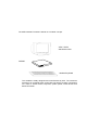
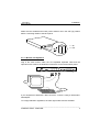
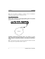
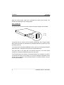
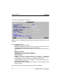
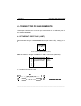
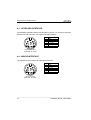
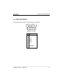
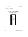
AX3000 Platine Terminal
Ethernet TCP/IP
Model 65E
Installation Guide
February 2002 - Ref: I65EE0210-1
Model AX3000/M65E
The reproduction of this material, in part or whole, is strictly prohibited. For
additional information, please contact:
14 Avenue du Québec
Bât. K2 EVOLIC - BP 728
91962 Courtabœuf cedex - FRANCE
Tel.: 33 1.69.28.27.27
Fax: 33 1.69.28.82.04
Email: [email protected]
The information in this document is subject to change without notice. AXEL
assumes no responsibility for any errors that may appear in this document.
All trademarks and registered trademarks are the property of their respective
holders.
© - 2001-2002 - AXEL - All Rights Reserved.
1 - SAFETY NOTICES .........................................................................................1
2 - INSTALLATION ..............................................................................................2
2.1 - DESCRIPTION .........................................................................................2
2.2 - INSTALLATION ........................................................................................2
2.2.1 - Monitor and keyboard ........................................................................3
2.2.2 - Ethernet Connection ..........................................................................4
2.2.3 - Auxiliary Ports ....................................................................................5
2.2.4 - AC Power Connection........................................................................5
2.2.5 - Power On ...........................................................................................6
3 - QUICK INSTALLATION .................................................................................7
4 - CONNECTOR PIN ASSIGNMENTS...............................................................9
4.1 - ETHERNET PORT RJ45 (10BT)..............................................................9
4.2 - SERIAL PORTS AUX1 AND AUX2 (RJ45) ............................................10
4.2.1 - RJ45-DB9 and RJ45-DB25 adaptors...............................................11
4.2.2 - Peripheral RJ45 cables ....................................................................11
4.3 - KEYBOARD INTERFACE ......................................................................12
4.4 - MOUSE INTERFACE .............................................................................12
4.5 - VIDEO INTERFACE ...............................................................................13
4.6 - PARALLEL INTERFACE ........................................................................14
5 - PROBLEM SOLVING ...................................................................................15
The AXEL AX3000 Terminal is based on a modular concept.
VGA / SVGA
standard monitor
AX3000
standard keyboard
The AX3000 is totally designed and manufactured by Axel. The terminal's
electronics is contained within a slim base unit which provides connections
for a VGA or SVGA monitor, keyboard, system printer, serial devices and
Ethernet network.
Safety Notices
1 - SAFETY NOTICES
Check AC voltage from the wall outlet is inside 220-240 Volts range.
The wall outlet used must be reached easily and as nearest as possible to the
AX3000 Platine Terminal to connect or disconnect the power cord.
Make sure to power off all devices before connecting or disconnecting any one
of them (monitor VGA cable, keyboard and serial or parallel cables).
In order to ensure compliance with European EMC regulations (EN 55022), it
is required that shielded cables be used when interfacing with other devices
(peripherals or computers).
To install and connect the keyboard and the monitor, refer to the respective
supplier installation manuals.
________________________________________________________________
Installation Guide - Model 65E
1
Installation
2 - INSTALLATION
This chapter provides information and instructions to install the AX3000 Model
65E.
2.1 - DESCRIPTION
A green LED, located on the face plate, indicates when the AX3000 is powered
on.
The AX3000 has the following connectors and switches on the rear panel:
- one power switch,
- one connector for the external power transformer cord,
- one connector for a VGA or SVGA monitor (colour or monochrome),
- one Mini-DIN connector for an AT/PS style keyboard,
- one PS/2 mouse connector,
- two auxiliary serial ports: RJ45 (AUX1 and AUX2),
- one auxiliary parallel port: female 25-pin (PARALLEL),
- one TCP/IP port: RJ45 (10BT).
2.2 - INSTALLATION
For safety reasons and to prevent component damage, do not apply power to
the AX3000 before connecting or disconnecting any cable. Do not plug in the
AX3000 power cord until all other connectors have been plugged in.
________________________________________________________________
2
Installation Guide - Model 65E
Installation
Make sure the AX3000 and monitor power switches are in the OFF (0) position
before connecting cables to the back panel.
1 : On
0 : Off
2.2.1 - Monitor and keyboard
Plug in the VGA monitor cable, the AT-compatible keyboard cable and the
optional mouse cable to the dedicated connectors on the terminal back panel:
If your keyboard is fitted with a DIN connector, connect it using a DIN-to-MiniDIN adaptor.
To comply with EMC regulations, the VGA signal cable must be shielded.
________________________________________________________________
Installation Guide - Model 65E
3
Installation
Note: when the terminal is installed in a cabinet or rack, it is essential to
maintain air circulation around the VGA/SVGA monitor.
2.2.2 - Ethernet Connection
Plug the RJ45 connector on the end of the 10Base-T cable into the socket
labelled 10BT on the back of the AX3000 (see chapter 4.1 for technical
specifications and pin assignments).
ETHERNET
ETHERNET CONNECTION INDICATOR LIGHT: This indicator is a green
LED, located next to the RJ45 connector on the rear of the terminal. It
lights to indicate a satisfactory connection to the Ethernet circuit (server
or hub).
Note: if the LED does not light, check that the Ethernet connector and cable
both comply with the specifications listed in chapter 4.1.
________________________________________________________________
4
Installation Guide - Model 65E
Installation
2.2.3 - Auxiliary Ports
AX3000 Models 65E have three auxiliary ports as a standard feature:
- MAIN-AUX1: bi-directional serial port, RJ45 connector,
- AUX2:
bi-directional serial port, RJ45 connector,
- PARALLEL: parallel port, female 25-pin connector.
Cable pin assignments are listed in chapter 4.
To comply with EMC regulations, the serial cables must be shielded.
2.2.4 - AC Power Connection
An Axel external power transformer must be used, to convert mains voltage at
the wall outlet to low voltage for the AX3000 Model 35.
Before connecting, make sure the AX3000 and monitor power switches are both
in the OFF (0) position.
Plug the plastic moulded cord connector of the external power transformer
(ref. AXP/EC9.8) to the AX3000 power connector. Then plug the transformer
into the AC wall outlet.
Warning: Only use the Axel external transformer supplied with your
AX3000 Model 65E. Use of any other transformer may cause permanent
damage to the AX3000.
________________________________________________________________
Installation Guide - Model 65E
5
Installation
Plug the monitor power cable into a grounded AC mains power socket. The
monitor does not require low voltage power.
2.2.5 - Power On
The power switch on the rear panel controls the power supply to the AX3000.
1 : On
0 : Off
The green LED on the front of the terminal should light, and a single audible
beep should be heard, to indicate that the AX3000 terminal is powered up and
operating correctly.
To indicate correct keyboard initialisation after power-up, the keyboard indicator
lights 'Num lock', 'Caps lock' and 'Scroll lock' should flash twice.
The green LED on the right side of the RJ45 connector on the back panel
remains lit, to indicate a satisfactory Ethernet connection.
If the terminal does not function as described above (for example if it emits a
continuous tone sound, or two beeps, or if an error message is displayed on the
screen) refer to chapter 5. If the terminal still does not operate properly, call your
service representative.
________________________________________________________________
6
Installation Guide - Model 65E
Quick Installation
3 - QUICK INSTALLATION
This chapter describes the quick set-up procedure for the TCP/IP Platine
terminal.
The following command sequence is used to enter the AX3000 Set-Up:
All the AX3000 set-up parameters (network environment, session settings and
auxiliary port settings) can be adjusted through this set-up.
For more information, refer to the guide: TCP/IP AX3000 - User's Manual.
But, for a fast and reliable installation, the AX3000 provides a quick set-up
function. This quick set-up function is dedicated to a typical environment:
- only one host,
- an optional router,
- all the virtual terminals have the same settings,
- a lpd or a Prt5250 printer is available.
To enter the quick set-up, select [Configuration]→[Quick Set-up] and press
<CR>. A warning message is displayed, press <CR> to continue.
________________________________________________________________
Installation Guide - Model 65E
7
Quick Installation
The quick set-up dialog box is displayed:
Note: this box is automatically called when the AX3000 is powered up for the
first time.
Quick set-up parameters:
- Keyboard: keyboard nationality.
- Number of sessions: maximum number of sessions. These sessions are
automatically associated with the host described above.
- Configuration: virtual terminal settings. This choice is selected from a
list.
- AX3000 IP address
- Default router: optional router IP address.
- Host Name: name of the only accessible host
- Host IP address
- Enable: Configuring printers attached to AX3000. If ‘Pre-defined
Configuration’ is set to 5250 and a hostname is defined, PRT5250 is
automatically selected. If not LPD is the default printing system.
- Printer Name (accessible only if "Enable" is set): this is the printer name
at the operating system level.
- Manufacturer Type and Model (accessible only with Prt5250): printer
type and model.
After confirmation, all the AX3000 set-up parameters are updated.
________________________________________________________________
8
Installation Guide - Model 65E
Connector Pin Assignments
4 - CONNECTOR PIN ASSIGNMENTS
This chapter describes the connector pin assignments for the different ports of
the AX3000 Model 65E.
4.1 - ETHERNET PORT RJ45 (10BT)
Recommended wiring is a non-shielded twisted-pair cable (UTP), category 3 or
5
! " # $ %
RJ45 connector (Model 65E rear panel)
Note: the maximum length of a 10Base-T cable is 100 meters (330 feet).
Pin
1
2
3
4
5
6
7
8
Signal Name
TX+ (Transmitted Data)
TX- (Transmitted Data)
RX+ (Received Data)
----RX- (Received Data)
-----
Direction
Input
Input
Output
----Output
-----
a - AX3000 Connected to a HUB
________________________________________________________________
Installation Guide - Model 65E
9
Connector Pin Assignments
b - AX3000 Connected to an Ethernet Controller
IMPORTANT: the cable is composed of two twisted pairs. The two wires
TX+ / TX- must belong to one pair and the two wires RX+ / RX- must
belong to the other pair.
4.2 - SERIAL PORTS AUX1 AND AUX2 (RJ45)
These serial ports are bi-directional ports (for printers, bar-code readers, touch
screens, etc):
! " # $ %
AUX1 and AUX2 connectors
(Model 65E rear panel)
Pin
1
2
3
4
5
6
7
8
Signal Name
RTS (Request To Send)
DTR (Data Terminal Ready)
RD (Received Data)
SG (Signal Ground)
CTS (Clear to Send)
TD (Transmitted Data)
--DCD (Data Carrier Detected)
Direction
Output
Output
Input
--Input
Output
--Input
________________________________________________________________
10
Installation Guide - Model 65E
Connector Pin Assignments
4.2.1 - RJ45-DB9 and RJ45-DB25 adaptors
Pin assignment for an adaptor between the peripheral cable and the AX3000
RJ45 connector:
& & " # $"%
!
" '# "%
(
4.2.2 - Peripheral RJ45 cables
Pin assignment for a direct connection of a peripheral to the AX3000 RJ45
connector:
& & )%" '# $"%
)%" # "%
(
________________________________________________________________
Installation Guide - Model 65E
11
Connector Pin Assignments
4.3 - KEYBOARD INTERFACE
The AX3000 keyboard interface is a Mini-DIN connector. To connect a keyboard
which has a DIN connector, use a DIN-to-Mini-DIN adaptor:
Pin
1
2
3
4
5
6
Signal name
Data
--Ground
+ 5 V DC
Clock
---
Keyboard connector
(Model 65E rear panel)
4.4 - MOUSE INTERFACE
The AX3000 mouse interface is a Mini-DIN connector:
Pin
1
2
3
4
5
6
Signal name
Data
--Ground
+ 5 V DC
Clock
---
Mouse connector
(Model 65E rear panel)
________________________________________________________________
12
Installation Guide - Model 65E
Connector Pin Assignments
4.5 - VIDEO INTERFACE
The AX3000 video interface is VGA and SVGA compatible:
"
!
&
"
'
!
%
$
#
VGA/SVGA connector
(Model 65E, rear panel)
Pin
1
2
3
4
5
6
7
8
9
10
11
12
13
14
15
Signal name
Red
Green
Blue
--Ground
Ground
Ground
Ground
Ground
Ground
----Horizontal sync.
Vertical sync.
---
________________________________________________________________
Installation Guide - Model 65E
13
Connector Pin Assignments
4.6 - PARALLEL INTERFACE
The Platine terminal Model 65E is equipped with a parallel port.
"
!
&
'
%
$
&
#
'
"
%
!
$
#
"
!
Parallel connector
(Model 65E, rear panel)
Pin
1
2
3
4
5
6
7
8
9
10
11
12
13
14
15
16
17
18
19
20
21
22
23
24
25
Signal Name
Strobe
Data 0
Data 1
Data 2
Data 3
Data 4
Data 5
Data 6
Data 7
ACK (Acknowledge)
Busy
PE (Paper End)
SLCT (Select)
Auto Feed XT
Error
Init
SLCT IN
Ground
Ground
Ground
Ground
Ground
Ground
Ground
Ground
________________________________________________________________
14
Installation Guide - Model 65E
Problem Solving
5 - PROBLEM SOLVING
This chapter describes some of the problems, that may occur during installation
of the AX3000 Model 65E, and offers possible solutions.
- THE VGA MONITOR VERTICAL SYNC IS LOST
Care must be taken with the VGA monitor. The default VGA frequency used by
the AX3000 is 72 Hertz. If the VGA monitor does not support this frequency, the
vertical sync will be lost. To fix this problem, either use a more modern monitor
or perform following operation:
Enter the AX3000 Set-Up (<Ctrl><Alt><Ecs>) and press <F12>. The
VGA frequency is set to 56 Hertz and the display becomes visible (this
emergency procedure modifies the VGA frequency only during the set-up
stage).
Then select the [Configuration]→[Advanced]→[Tunings] menu. Within
the dialog box, select the 'Scan frequency' parameter and press
<spacebar> to enter the associated dialog box. A frequency value can be
selected among the 2 available (60 and 72 Hertz).
- GREEN FRONT INDICATOR DOESN'T LIGHT, OR NO BEEP WHEN
YOU PRESS POWER SWITCH
Check there is power at the wall outlet and power cord connections.
- CONTINUOUS TONE SOUNDS AFTER THE TERMINAL HAS BEEN
SWITCHED ON
This alarm indicates a hardware failure. Report the problem to your service
representative.
________________________________________________________________
Installation Guide - Model 65E
15
Problem Solving
- AFTER THE TERMINAL HAS BEEN SWITCHED ON, THE MESSAGES
'NO ETHERNET BOARD PRESENT'
ETHERNET BOARD' APPEAR
AND
'CANNOT
ATTACH
This message indicates a hardware failure. Report the problem to your service
representative.
- A DOUBLE-BEEP SOUNDS
After switching on the terminal, a double beep may sound, a few seconds after
the normal first beep.
This signal indicates that keyboard initialisation has failed. Check the keyboard
connection to the terminal back panel.
It is possible for the keyboard to function correctly, despite this double-beep
signal. As a quick test of keyboard operation, enter set-up mode by pressing the
<Ctrl><Alt><Esc> keys simultaneously. If set-up mode is working, you can
ignore the double beep signal and use the terminal normally.
- ETHERNET CONNECTION INDICATOR DOES NOT LIGHT
This indicator is the green LED located next to the network connector on the
Model 65E terminal back panel.
Failure to light when the terminal is switched on may be due to any of the
following:
- the Ethernet cable is disconnected at the far end,
- the device (host or hub), to which the network cable is connected, is not
switched on,
- there is a fault on the Ethernet cable or the cable is wired with incorrect
pin assignments.
________________________________________________________________
16
Installation Guide - Model 65E
Problem Solving
- NO LOGIN WHEN THE 'CONNECTING...' MESSAGE IS DISPLAYED
Check the Ethernet cables are correctly connected and networked devices
(hubs or servers) are switched on.
No connection (and no login) can also be due to a wrong terminal setting during
the TCP/IP set-up (for example a wrong IP address).
- INCORRECT APPEARANCE OF SOFTWARE DISPLAYED ON THE
AX3000
Check the values of parameters set using Terminal Set-Up. Check that the
correct terminal emulation has been chosen.
Check that the TERM environment variable (for the current UNIX shell)
corresponds to the emulation selected for the terminal (in AX3000 Set-Up).
- THE CONNECTED PRINTER DOES NOT WORK
Check that the cable pin assignment is correct and that the port being used
(AUX1, AUX2 or PARALLEL) has been correctly selected in AX3000 Set-Up.
Test the printer in local mode by pressing the <Prt Scr> key. A hardcopy of the
screen should be printed.
________________________________________________________________
Installation Guide - Model 65E
17
14 Avenue du Québec
Bât. K2 EVOLIC - BP 728
91962 Courtabœuf cedex - FRANCE
Tel.: 33 1.69.28.27.27
Fax: 33 1.69.28.82.04
Email: [email protected]