1
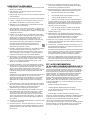
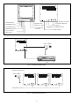
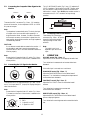
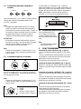
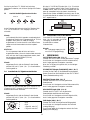
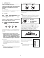
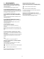
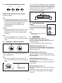
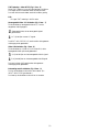
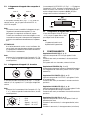
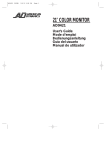
LTC 2814/90
Color Monitor
Eng
Installation Instructions
F
Philips
Communication
Security & Imaging
D
E
NL
I
Eng
Installation Instructions...........................................................................................................................................................................1.1
F
Manuel d’utilisation ..................................................................................................................................................................................2.1
D
Installationshinweise ................................................................................................................................................................................3.1
E
Instrucciones para la instalación ...........................................................................................................................................................4.1
NL
Bedieningsvoorschrift ..............................................................................................................................................................................5.1
I
Istruzioni per l’installazione ...................................................................................................................................................................6.1
16. Servicing - Do not attempt to service this unit yourself as opening or
removing covers may expose you to dangerous voltage or other hazards.
Refer all servicing to qualified service personnel.
IMPORTANT SAFEGUARDS
1. Read Instructions - All the safety and operating instructions should be read
before the unit is operated.
17. Damage Requiring Service - Unplug the unit from the outlet and refer
servicing to qualified service personnel under the following conditions:
2. Retain Instructions - The safety and operating instructions should be
retained for future reference.
3. Heed Warnings - All warnings on the unit and in the operating instructions
should be adhered to.
4. Follow Instructions - All operating and use instructions should be followed.
a.
When the power-supply cord or plug is damaged.
b.
If liquid has been spilled, or objects have fallen into the unit.
c.
If the unit has been exposed to rain or water.
d.
If the unit does not operate normally by following the operating
instructions. Adjust only those controls that are covered by the operating
instructions, as an improper adjustment of other controls may result in
damage and will often require extensive work by a qualified technician to
restore the unit to its normal operation.
5. Cleaning - Unplug the unit from the outlet before cleaning. Do not use
liquid cleaners or aerosol cleaners. Use a damp cloth for cleaning.
6. Attachments - Do not use attachments not recommended by the product
manufacturer as they may cause hazards.
e.
7. Water and Moisture - Do not use this unit near water - for example, near a
bath tub, wash bowl, kitchen sink, or laundry tub, in a wet basement, near
a swimming pool, in an unprotected outdoor installation, or any area which
is classified as a wet location.
If the unit has been dropped or the cabinet has been damaged.
f.
When the unit exhibits a distinct change in performance--this
indicates a need for service.
18. Replacement Parts - When replacement parts are required, be sure the
service technician has used replacement parts specified by the manufacturer
or have the same characteristics as the original part. Unauthorized
substitutions may result in fire, electric shock or other hazards.
8. Accessories - Do not place this unit on an unstable stand, tripod, bracket,
or mount. The unit may fall, causing serious injury to a person and serious
damage to the unit. Use only with a stand, tripod, bracket, or mount
recommended by the manufacturer, or sold with the product. Any
mounting of the unit should follow the manufacturer's instructions, and
should use a mounting accessory recommended by the manufacturer.
19. Safety Check - Upon completion of any service or repairs to this unit, ask
the service technician to perform safety checks to determine that the unit is
in proper operating condition.
An appliance and cart combination should be moved with care.
Quick stops, excessive force, and uneven surfaces may cause the
appliance and cart combination to overturn.
20. Coax Grounding - If an outside cable system is connected to the unit, be
sure the cable system is grounded. U.S.A. models only--Section 810 of the
National Electrical Code, ANSI/NFPA
9. Ventilation - Openings in the enclosure, if any, are provided for ventilation
and to ensure reliable operation of the unit and to protect it from
overheating. These openings must not be blocked or covered. This unit
should not be placed in a built-in installation unless proper ventilation is
provided or the manufacturer's instructions have been adhered to.
No.70-1981, provides information with respect to proper grounding of the
mount and supporting structure, grounding of the coax to a discharge unit,
size of grounding conductors, location of discharge unit, connection to
grounding electrodes, and requirements for the grounding electrode.
10. Power Sources - This unit should be operated only from the type of power
source indicated on the marking label. If you are not sure of the type of
power supply you plan to use, consult your appliance dealer or local power
company. For units intended to operate from battery power, or other
sources, refer to the operating instructions.
21. Lightning - For added protection of this unit during a lightning storm, or
when it is left unattended and unused for long periods of time, unplug it
from the wall outlet and disconnect the cable system. This will prevent
damage to the unit due to lightning and power-line surges.
11. Grounding or Polarization - This unit may be equipped with a polarized
alternating-current line plug (a plug having one blade wider than the other).
This plug will fit into the power outlet only one way. This is a safety
feature. If you are unable to insert the plug fully into the outlet, try
reversing the plug. If the plug should still fail to fit, contact your electrician
to replace your obsolete outlet. Do not defeat the safety purpose of the
polarized plug.
FCC & ICES INFORMATION
(U.S.A. AND CANADIAN MODELS ONLY)
WARNING - This equipment has been tested and found to comply with the
limits for a Class B digital device, pursuant to Part 15 of the FCC Rules and
ICES-003 of Industry Canada. These limits are designed to provide reasonable
protection against harmful interference when the equipment is operated in a
residential installation. This equipment generates, uses and can radiate radio
frequency energy and, if not installed and used in accordance with the
instructions, may cause harmful interference to radio communications.
However, there is no guarantee that interference will not occur in a particular
installation. If this equipment does cause harmful interference to radio or
television reception, which can be determined by turning the equipment off and
on, the user is encouraged to try to correct the interference by one or more of
the following measures:
Alternately, this unit may be equipped with a 3-wire grounding-type plug, a
plug having a third (grounding) pin. This plug will only fit into a
grounding-type power outlet. This is a safety feature. If you are unable to
insert the plug into the outlet, contact your electrician to replace your
obsolete outlet. Do not defeat the safety purpose of the grounding-type
plug.
12. Power-Cord Protection - Power-supply cords should be routed so that they
are not likely to be walked on or pinched by items placed upon or against
them, paying particular attention to cords and plugs, convenience
receptacles, and the point where they exit from the appliance.
-
Reorient or relocate the receiving antenna.
-
Increase the separation between the equipment and receiver.
13. Power Lines - An outdoor system should not be located in the vicinity of
overhead power lines or other electric light or power circuits, or where it
can fall into such power lines or circuits. When installing an outdoor
system, extreme care should be taken to keep from touching such power
lines or circuits as contact with them might be fatal. U.S.A. models only refer to the National Electrical Code Article 820 regarding installation of
CATV systems.
-
Connect the equipment into an outlet on a circuit different from that to
which the receiver is connected.
-
Consult the dealer or an experienced radio/TV technician for help.
14. Overloading - Do not overload outlets and extension cords as this can result
in a risk of fire or electric shock.
The user may find the following booklet prepared by the Federal
Communications Commission helpful: "How to Identify and Resolve Radio-TV
Interference Problems". This booklet is available from the U.S. Government
Printing Office, Washington, DC 20402, Stock No.004-000-00345-4.
Intentional or unintentional changes or modifications not expressly approved by
the party responsible for compliance shall not be made. Any such changes or
modifications could void the user's authority to operate the equipment.
15. Object and Liquid Entry - Never push objects of any kind into this unit
through openings as they may touch dangerous voltage points or short-out
parts that could result in a fire or electric shock. Never spill liquid of any
kind on the unit.
3
1 VOLUME control
2 SHARPNESS control
3 CONTRAST control
4 BRIGHTNESS control
10 AUDIO connectors
11 Composite VIDEO A/B
9 POWER switch
8 VIDEO A,B switch
12 Y/C connectors
13 Y/C IMPEDANCE switch
7 Composite video
Y/C switch
14 Power connector
5 COLOR control
6 TINT control
Fig. 1 Monitor LTC 2814
VIDEO CAMERA
VCR
Fig. 2 Connecting a single monitor
MULTIPLE CONNECTION
VIDEO CAMERA
FROM VIDEO OUTPUT
Fig. 3 Connecting multiple monitors
4
SAFETY PRECAUTIONS
CONTENTS
Safety Precautions . . . . . . . . . . . . . . . . . . . . . . . . .1.1
Cover Removal . . . . . . . . . . . . . . . . . . . . . . . . . . .1.1
CAUTION: TO REDUCE THE RISK OF
ELECTRICAL SHOCK, DO NOT OPEN COVERS.
NO USER SERVICEABLE PARTS INSIDE. REFER
SERVICING TO QUALIFIED SERVICE
PERSONNEL.
This label may appear on the bottom of the unit due to space
limitations.
The lightning flash with an arrowhead symbol,
within an equilateral triangle, is intended to alert
the user to the presence of un-insulated
“dangerous voltage” within the product's enclosure
that may be of sufficient magnitude to constitute a
risk of electric shock to persons.
The exclamation point within an equilateral
triangle is intended to alert the user to presence of
important operating and maintenance (servicing)
instructions in the literature accompanying the
appliance.
WARNING
TO PREVENT FIRE OR SHOCK HAZARD, DO
NOT EXPOSE UNITS NOT SPECIFICALLY
DESIGNED FOR OUTDOOR USE TO RAIN OR
MOISTURE.
Attention: Installation should be performed by
qualified service personnel only in accordance with
the National Electrical Code or applicable local
codes.
1.
1.1
Introduction . . . . . . . . . . . . . . . . . . . . . . . . . . . . .1.1
Monitor . . . . . . . . . . . . . . . . . . . . . . . . . . . . . . . . .1.1
2
2.1
2.2
2.3
2.4
2.5
Installation . . . . . . . . . . . . . . . . . . . . . . . . . . . . . .1.1
Ventilation . . . . . . . . . . . . . . . . . . . . . . . . . . . . . .1.1
Power . . . . . . . . . . . . . . . . . . . . . . . . . . . . . . . . . .1.1
Connecting the Composite Video Signal to the
Monitor . . . . . . . . . . . . . . . . . . . . . . . . . . . . . . . . .1.2
Connecting the Y/C Signal to the monitor . . . . . . .1.2
Connecting Audio to the Monitor . . . . . . . . . . . . .1.2
3
Operation . . . . . . . . . . . . . . . . . . . . . . . . . . . . . .1.2
1
INTRODUCTION
1.1 Monitor
Read these instructions carefully.
This 14 inch (viewable picture area 34 cm (13.3 inch)) monitor
is intended for display of PAL or NTSC standard color pictures
in CCTV systems. The monitor accepts either two Composite
Video inputs, with loop-through BNC connections, or one Y/C
loop-through input, with two 4-pin mini-DIN connectors,
located on the rear of the monitor.
The Composite Video-Y/C switch is located at the front.
For applications that require audio, two audio phono jack
connectors are provided on the rear panel.
2
INSTALLATION
Up to three monitors can be connected using the loop-through
feature of this unit (Fig. 3).
COVER REMOVAL
WARNING:
REMOVAL OF THE COVER
SHOULD ONLY BE PERFORMED
BY QUALIFIED SERVICE
PERSONNEL - NOT USER
SERVICEABLE. THE UNIT SHOULD
ALWAYS BE UNPLUGGED,
BEFORE REMOVING THE COVER
AND REMAIN UNPLUGGED
WHILE THE COVER IS REMOVED.
When this monitor is connected to additional monitors, the
same picture can be obtained on all the connected monitors.
2.1 Ventilation
In order to prevent overheating, ensure that the ventilation
openings in the monitor are not covered.
2.2
Power
Model
No.
LTC 2814/90
Rated
Voltage
120/230 VAC
50/60 Hz
Voltage
Range
100 to 240
Power at
Sync
Rated Voltage Format
70 W
PAL/
NTSC
The LTC 2814/90 monitor is delivered with a 2 pole Euro
connector and a 3 pole US style connector.
1.1
2.3
The Y/C IMPEDANCE switch (Fig. 1 item - 13) selects the SVIDEO impedance. Set the switch to the 75 Ω position when
only one monitor is used or when the monitor is used as the
last monitor in a chain. Set to HIGH when another monitor is
connected to the Y/C OUT connector for loop-through
operation.
Connecting the Composite Video Signal to the
Monitor
VIDEO A
VIDEO B
IN
OUT
IN
OUT
There are four BNC connectors (Fig. 1 item - 11), located on
the rear of the monitor, for the composite VIDEO A/ VIDEO
B inputs and outputs.
Note:
The impedance is automatically set to 75 ohm by the input
of a signal on the input connector while operating in a
single connection mode. However, if a cable is connected
to the output connector, the connection is placed into the
open status by the multiple connection and high impedance
is automatically selected.
2.5 Connecting Audio to the Monitor
There are two RCA phone type
AUDIO
connectors (Fig. 1 item - 10) one for
the audio input and the other for
looping through to other video
monitors.
CAUTION:
Do not leave an unused cable connected to the monitor. If
a single cable is used, then it must be connected to the
input connector for the 75 ohm auto-termination selector to
function properly.
Note:
The audio in/out is not
dependent upon the VIDEO
input.
3
Note:
Ensure that the Composite Video-Y/C switch (Fig. 1 item 7), located on at the front of the monitor, is selected to the
correct position.
2.4
OUT
IN
OPERATION
VOLUME control (Fig. 1 item - 1)
Adjust the VOLUME control for the appropriate audio level.
Turn clockwise to increase sound and counterclockwise to
decrease it.
Connecting the Y/C Signal to the Monitor
If the audio input is not used, turn to minimum.
SHARPNESS control (Fig. 1 item - 2)
Adjust the SHARPNESS control for the desired overall
sharpness. Turn clockwise to increase picture sharpness and
counterclockwise to decrease it.
CONTRAST control (Fig. 1 item - 3)
Adjust the CONTRAST control for the desired overall
contrast.
There are two mini-DIN type connectors (Fig. 1 item - 12) for
the Y/C IN (Input) and OUT (Output) for looping-through to
other video monitors.
Turn clockwise to increase picture contrast and
counterclockwise to decrease it.
Note:
Ensure that the Composite Video-Y/C switch (Fig. 1 item 7), located on at the front of the monitor, is selected to the
correct position.
1
2
3
4
BRIGHTNESS control (Fig. 1 item - 4)
Adjust the BRIGHTNESS control for the desired overall
picture or display brightness.
GND
GND
Y signal IN or OUT
C signal IN or OUT
Turn clockwise for more brightness and counterclockwise for
less.
1.2
COLOR control (Fig. 1 item - 5)
Adjust the COLOR control to set the color (saturation) level.
When turned counterclockwise, the color seems pale (low
color).
When turned clockwise, the color seems saturated (high color).
TINT control - only applicable for NTSC (Fig. 1 item - 6)
Adjust the TINT control for the proper color phase or flesh
tone.
When turned counterclockwise, the skin tone become reddish.
When turned clockwise, the skin tone become greenish.
Note:
There is no TINT control in PAL display.
Composite Video-Y/C Switch (Fig. 1 item - 7)
Set the switch to Composite Video or Y/C for the connected
video input option.
- Composite Video, when monitoring a composite signal.
- Y/C, when monitoring a Y/C signal.
The INPUT INDICATOR (Y/C) will illuminate when the
desired video input is selected.
Video A/B Switch (Fig. 1 item - 8)
Set the switch to A (video A in) or B (video B in) when the
Composite Video option is selected.
- A, when monitoring the composite video A signal.
- B, when monitoring the composite video B signal.
The Input Indicator (A;B) will illuminate when the desired
video input is selected
Power on/off Switch (Fig. 1 item - 9)
Press the switch to turn the monitor ON. (The INPUT
INDICATOR will illuminate.)
Press the switch again to turn the monitor OFF.
1.3
1.4
SECURITE
SOMMAIRE
1.
1.1
Consignes de sécurité . . . . . . . . . . . . . . . . . . . . . . .2.1
Dépose du boîtier . . . . . . . . . . . . . . . . . . . . . . . . .2.1
Introduction . . . . . . . . . . . . . . . . . . . . . . . . . . . .2.1
Moniteur . . . . . . . . . . . . . . . . . . . . . . . . . . . . . . . .2.1
2
2.1
2.2
2.3
2.4
2.5
Installation . . . . . . . . . . . . . . . . . . . . . . . . . . . . . .2.1
Ventilation . . . . . . . . . . . . . . . . . . . . . . . . . . . . . .2.1
Alimentation . . . . . . . . . . . . . . . . . . . . . . . . . . . . .2.1
Connexion du signal vidéo composite au moniteur .2.2
Connexion du signal Y/C au moniteur . . . . . . . . . .2.2
Connexion audio au moniteur . . . . . . . . . . . . . . . .2.2
3
Fonctionnement . . . . . . . . . . . . . . . . . . . . . . . . . .2.2
L’éclair fléché dans un triangle équilatéral avertit
l’utilisateur de la présence d’une haute tension
non isolée à l’intérieur de l’appareil. Elle peut être
d’une magnitude suffisante pour constituer un
risque d’electrocution.
1
INTRODUCTION
Le point d’exclamation à l’intérieur d’un triangle
équilatéral avertit l’utilisateur de la présence
d’instructions importantes d’utilisation et de
maintenance dans la documentation
accompagnant l’appareil.
Ce moniteur de 14 pouces (format d'image affichable 34 cm
[13.3 pouces]) est destiné à l'affichage d'images couleur à la
norme PAL ou NTSC dans les systèmes TVCF. Le moniteur
accepte soit deux entrées vidéo composites, avec connexions
BNC en boucle, soit une entrée en boucle Y/C, avec deux mini
connecteurs DIN à 4 broches situés à 'arrière du moniteur.
DANGER: POUR ÉVITER TOUT RISQUE
D’ÉLECTROCUTION, NE PAS OUVRIR LE
BOÎTIER. IL N’Y A PAS DE PIÈCES
REMPLAÇABLES À L’INTÉRIEUR. POUR TOUTE
RÉVISION, S’ADRESSER À UN TECHNICIEN
SPÉCIALISÉ.
Cet étiquette peut apparaître en dessous de l’appareil dû aux
limitations d’espace.
ATTENTION:
POUR ÉVITER UN INCENDIE OU UNE
ÉLECTROCUTION, NE PAS EXPOSER LES
APPAREILS QUI NE PAS CONÇUS
SPÉCIFIQUEMENT POUR USAGE EXTÉRIEUR À
LA PLUIE OU À L’HUMIDITÉ.
Attention: L’installation doit être effectuée
uniquement par du personnel de service qualifié
conformément à la réglementation du Code
Electrique National ou à la réglementation locale.
DÉMONTAGE DU COUVERCLE
LE DÉMONTAGE DU
COUVERCLE ET LE RÉGLAGE
DES COMMANDES INTERNES
DOIVENT ÊTRE EFFECTUÉS PAR
DU PERSONNEL QUALIFIÉ- PAS
DE SERVICE PAR L'UTILISATEUR.
L'APPAREIL DOIT TOUJOURS
ÊTRE DÉBRANCHÉ LORSQUE
L'ON RETIRE LE COUVERCLE ET
DOIT RESTER DÉBRANCHÉ
PENDANT QUE LE COUVERCLE
EST ÔTÉ.
1.1 Moniteur
Lire attentivement ces instructions.
Le commutateur Y/C vidéo composite est à l'avant du
moniteur.
Pour les applications qui requièrent une connexion audio, deux
fiches phono audio sont prévues sur le panneau arrière.
2
INSTALLATION
Il est possible de connecter jusqu'à trois moniteurs avec l'option
de boucle de cet appareil (Fig. 3).
Lorsque ce moniteur est relié à d'autres moniteurs, on obtient la
même image sur tous les moniteurs.
2.1 Ventilation
Pour éviter les risques de surchauffage, s'assurer que les prises
d'air de ventilation du moniteur sont dégagées.
2.2
Alimentation
N° de
modèle
LTC 2814/90
Tension
nominale
120/230 Vc.a.
50/60 Hz
Plage de Puissance à la
Format
tension tension nominale sync
100 à 240 70 W
PAL/
NTSC
Le moniteur LTC 2814/90 est livré avec un connecteur Euro
bipolaire, est livré avec un connecteur tripolaire de type
américain.
2.1
2.3
Le commutateur Y/C IMPEDANCE (Fig. 1, repère 13)
sélectionne l'impédance S-VIDEO. Régler le commutateur à la
position 75 Ω lorsqu'un seul moniteur est utilisé ou lorsque le
moniteur est le dernier de la chaîne. Régler le commutateur à
HIGH (haute) lorsqu'un autre moniteur est raccordé au
connecteur Y/C OUT pour le fonctionnement en boucle.
Connexion du signal vidéo composite au
moniteur
VIDEO A
VIDEO B
IN
OUT
IN
OUT
Quatre connecteurs BNC (Fig. 1, repère 11) situés à l'arrière du
moniteur sont prévus pour les entrées et sorties VIDEO
A/VIDEO B composites.
Note :
L'impédance est réglée automatiquement à 75 ohms par
l'entrée d'un signal sur le connecteur d'entrée pendant le
fonctionnement en mode de connexion simple. Toutefois, si
l'on raccorde un câble au connecteur de sortie, la connexion
est placée en état ouvert par la connexion multiple et
l'impédance haute est sélectionnée automatiquement.
2.5 Connexion de l'audio au moniteur
Deux connecteurs phono RCA
AUDIO
(Fig. 1, élément 10) sont prévus :
l'un pour l'entrée audio et l'autre
pour le bouclage à d'autres moniteurs
vidéo.
ATTENTION :
Ne pas laisser les câbles inutilisés branchés au moniteur. Si
l'on utilise un seul câble, il doit être raccordé au connecteur
d'entrée pour que le sélecteur à auto terminaison de
75 ohms puisse fonctionner correctement.
Note :
L'entrée/sortie audio ne dépend
pas de l'entrée VIDEO.
3
Note :
S'assurer que le commutateur Composite Video-Y/C (Fig.
1, repère 7) situé à l'avant du moniteur est sélectionné à la
position correcte.
2.4
OUT
IN
FONCTIONNEMENT
Commande de volume (VOLUME) (Fig. 1, repère 1)
Tourner la commande de manière à obtenir le niveau sonore
voulu.
Tourner la commande dans le sens des aiguilles d'une montre
pour augmenter le niveau sonore et dans le sens contraire des
aiguilles d'une montre pour le diminuer.
Si l'entrée audio n'est pas utilisée, tourner au minimum.
Connexion du signal Y/C au moniteur
Commande de netteté (SHARPNESS) (Fig. 1, repère 2)
Appuyer sur ce bouton pour régler la netteté de l'image. Régler
la valeur au moyen des boutons de volume (la valeur par défaut
est 50).
Deux mini connecteurs DIN (Fig. 1, repère 12) sont prévus
pour Y/C IN (entrée) et OUT (sortie) pour assurer le bouclage
avec d'autres moniteurs vidéo.
Commande de contraste (CONTRAST) (Fig. 1, repère 3)
Tourner la commande de manière à obtenir le contraste général
voulu.
Tourner la commande dans le sens des aiguilles d'une montre
pour augmenter le contraste de l'image et dans le sens contraire
des aiguilles d'une montre pour le diminuer.
Note :
S'assurer que le commutateur Composite Video-Y/C (Fig.
1, repère 7) situé à l'avant du moniteur est sélectionné à la
position correcte.
1
2
3
4
Commande de luminosité (BRIGHTNESS) (Fig. 1, repère
4)
Tourner la commande de manière à obtenir la luminosité de
l'image globale ou de l'affichage voulue.
Tourner la commande dans le sens des aiguilles d'une montre
pour augmenter la luminosité et dans le sens contraire des
aiguilles d'une montre pour la diminuer.
MASSE
MASSE
ENTRE ou SORTIE signal Y
ENTREE ou SORTIE signal C
2.2
Commande de couleur (COLOR) (Fig. 1, élément 5)
Tourner la commande pour régler le niveau de couleur
(saturation).
Lorsqu'elle est tournée dans le sens contraire des aiguilles d'une
montre, la couleur semble pâle (couleur basse).
Lorsqu'elle est tournée dans le sens des aiguilles d'une montre,
la couleur semble saturée (couleur haute).
Commande de teinte (TINT) - NTSC seulement (Fig. 1,
élément 6)
Tourner la commande de manière à obtenir la phase de couleur
ou la couleur de peau voulue.
Lorsqu'elle est tournée dans le sens contraire des aiguilles d'une
montre, la peau prend une teinte rougeâtre.
Lorsqu'elle est tournée dans le sens des aiguilles d'une montre,
la peau prend une teinte verdâtre.
Note :
La version PAL ne comporte pas de commande de teinte.
Commutateur Composite Video-Y/C (Fig. 1, repère 7)
Régler le commutateur sur Composite Video ou Y/C en
fonction de l'option d'entrée vidéo raccordée.
- Composite Video – pour surveiller un signal composite.
- Y/C – pour surveiller un signal Y/C.
Le voyant d'entrée (Y/C) s'allume lorsque l'entrée vidéo voulue
est sélectionnée.
Commutateur Video A/B (Fig. 1, repère 8)
Régler le commutateur sur A (entrée vidéo A) ou B (entrée
vidéo B) lorsque l'option Composite Video est sélectionnée.
- A – pour surveiller le signal composite vidéo A.
- B – pour surveiller le signal composite vidéo B.
Le voyant d'entrée (A;B) s'allume lorsque l'entrée vidéo voulue
est sélectionnée.
Interrupteur général (Fig. 1, repère 9)
Appuyer sur l'interrupteur pour mettre le moniteur sous
tension. (Le voyant d'entrée s'allume.)
Appuyer à nouveau sur le commutateur pour mettre le moniteur
hors tension.
2.3
2.4
SICHERHEITSVORKENHRUNGEN
INHALTSVERZEICHNIS
Sicherheitsvorkehrungen . . . . . . . . . . . . . . . . . . . . .3.1
Entfernung der Abdeckung . . . . . . . . . . . . . . . . . . .3.1
WARNUNG: VERHINDERN SIE EINEN
MÖGLICHEN ELEKTROSCHLAG, INDEM SIE
DIE ABDECKUNG NICHT ENTFERNEN.
WENDEN SIE SICH BEI DER WARTUNG AN
DAFÜR QUALIFIZIERTES PERSONAL.
Dieses Zeichen kann aus Platzgründen auf der Unterseite des
Gerätes angebracht sein.
Dieses Zeichen weist den Benutzer auf die nicht
isolierte Hochspannung innerhalb der Anlage
hin. Es besteht die Gefahr eines Elektroschlages.
Achtung!: Die Installation sollte nur von
qualifiziertem Kundendienstpersonal gemäß
jeweilig zutreffender Elektrovorschriften ausgeführt werden.
ENTFERNUNG DER ABDECKUNG
DIE ENTFERNUNG DER
ABDECKUNG UND HANTIEREN
IM INNERN DES GERÄTES
SOLLTEN NUR VON
QUALIFIZIERTEM PERSONAL
ERFOLGEN. DER STECKER DES
GERÄTES SOLLTE IMMER AUS
DER STECKDOSE GEZOGEN
WERDEN, BEVOR MAN DIE
ABDECKUNG ENTFERNT, UND
NICHT WIEDER
HINEINGESTECKT WERDEN,
SOLANGE DIE ABDECKUNG
ENTFERNT IST.
Einleitung . . . . . . . . . . . . . . . . . . . . . . . . . . . . . . .3.1
Monitor . . . . . . . . . . . . . . . . . . . . . . . . . . . . . . . . .3.1
2
2.1
2.2
2.3
2.4
2.5
Installation . . . . . . . . . . . . . . . . . . . . . . . . . . . . . .3.1
Belüftung . . . . . . . . . . . . . . . . . . . . . . . . . . . . . . . .3.1
Stromversorgung . . . . . . . . . . . . . . . . . . . . . . . . . . .3.1
Anschluß des BAS-Signals an den Monitor . . . . . . . .3.2
Anschluß des Y/C-Signals an den Monitor . . . . . . . .3.2
Anschluß des Tons an den Monitor . . . . . . . . . . . . .3.2
3
Bedienung . . . . . . . . . . . . . . . . . . . . . . . . . . . . . . .3.2
1
Das Ausrufezeichen in dem gleichseitigen Dreieck
ist dazu da, den Benutzer auf wich-tige
Inbetriebnahme- und Instandhaltungsvorschriften hinzuweisen, die dem Gerät in Form
einer Broschüre beigelegt sind.
WARNUNG: UM DAS RISIKO VON FEUER
ODER ELEKTROSCHLAG ZU VERMEIDEN,
DARF WEDER DAS GERÄT SELBST, NOCH DAS
NETZGERÄT REGEN ODER FEUCHTIGKEIT
AUSGESETZT WERDEN.
1.
1.1
EINLEITUNG
1.1 Monitor
Bitte lesen Sie die vorliegende Anleitung aufmerksam durch.
Dieser 14 Zoll Monitor (sichtbarer Bildbereich 34 cm
[13.3 Zoll]) ist für die Anzeige von Farbbildern im PALStandard oder im NTSC-Standard in Überwachungsanlagen
(CCTV) konzipiert. An den Monitoren können entweder zwei
BAS-Signaleingänge (Durchschleifen-BNC-Buchse an der
Rückseite) oder ein Y/C-Durchschleifeneingang (zwei 4polige
Mini-DIN-Buchsen an der Rückseite) angeschlossen werden.
Der Schalter für den Wechsel zwischen BAS und Y/C befindet
sich an der Vorderseite des Monitors.
Für Anwendungen mit Ton sind zwei Tonabnehmerbuchsen an
der Geräterückseite vorhanden.
2
INSTALLATION
Unter Verwendung der Durchschleifenfunktion dieses Geräts
(Abb. 3) können bis zu drei Monitore angeschlossen werden.
Wenn dieser Monitor an weitere Monitore angeschlossen wird,
kann an allen angeschlossenen Monitoren das gleiche Bild
angezeigt werden.
2.1 Belüftung
Damit sich der Monitor nicht zu stark erwärmt, müssen die
Belüftungsöffnungen freigehalten werden.
2.2
Stromversorgung
ModellNennNr.
Spannung
LTC 2814/90 120/230 VAC
50/60 Hz
3.1
Spannungs- Leistung bei
Syncbereich
Nennspannung Format
100 bis 240 70W
PAL/
NTSC
Der Monitor der Serie LTC 2814/90 wird mit einem
zweipoligen Eurostecker, und mit einem 3poligen USA-Stecker
geliefert.
2.3
Mit dem Y/C IMPEDANZ-Schalter (Abb. 1, Nr. 13) wird die
S-VIDEO-Impedanz gewählt. Stellen Sie den Schalter auf die
75 Ohm Position, wenn nur ein Monitor verwendet wird oder
wenn der verwendete Monitor der letzte in einer Kette ist.
Setzen Sie den Schalter auf HIGH (hochohmig), wenn für den
Durchschleifen-Betrieb ein weiterer Monitor an die Buchse Y/C
OUT angeschlossen ist.
Anschluß des BAS-Signals an den Monitor
VIDEO A
VIDEO B
IN
OUT
IN
OUT
An der Rückseite des Monitors sind vier BNC-Buchsen (Abb.
1, Nr. 11) für die BAS-Ein- und -Ausgänge VIDEO A/B
vorhanden.
Hinweis:
Im Einzelanschluß wird die Impedanz normalerweise durch
Eingabe eines Signals in den Eingangsanschluß auf 75 Ohm
eingestellt. Wenn jedoch ein Kabel am Ausgang
angeschlossen ist, wird der Anschluß in den offenen Status
versetzt und es wird automatisch eine hohe Impedanz
gewählt.
2.5 Anschluß des Tons an den Monitor
Es sind zwei RCA-Klinkenverbindungen
AUDIO
(Abb. 1, Nr. 10) vorhanden, eine für den
Toneingang, die andere für das
Durchschleifen zu anderen
Videomonitoren.
Hinweis:
Der Toneingang/-ausgang ist nicht
vom VIDEO-Eingang abhängig.
ACHTUNG:
Ein nicht genutztes Kabel darf nicht am Monitor
angeschlossen bleiben. Wenn ein einzelnes Kabel verwendet
wird, muß es an den Eingang angeschlossen werden, damit
der automatische Abschlußwähler (75 Ohm)
ordnungsgemäß funktioniert.
3
BEDIENUNG
SCHÄRFETASTE-Regler [SHARPNESS] (Abb. 1, Nr. 2)
Drücken Sie diese Taste, um die Bilddarstellung einzustellen.
Ändern Sie den Wert der Bildschärfe mit den LAUTSTÄRKETasten (Standardeinstellung ist 50).
Anschluß des Y/C-Signals an den Monitor
KONTRAST-Regler (Abb. 1, Nr. 3)
Einstellen des KONTRASTS für den gewünschten
Gesamtkontrast.
Durch Drehen im Uhrzeigersinn wird der Bildkontrast erhöht,
durch Drehen gegen den Uhrzeigersinn vermindert.
Es sind zwei Mini-DIN-Buchsen (Abb. 1, Nr. 12) für Y/C IN
(Eingang) und OUT (Ausgang) für das Durchschleifen zu
anderen Videomonitoren vorhanden.
HELLIGKEITS-Regler (Abb. 1, Nr. 4)
Einstellen der HELLIGKEIT auf die gewünschte
Gesamthelligkeit des Bildes oder der Anzeige.
Durch Drehen im Uhrzeigersinn wird die Helligkeit erhöht,
durch Drehen gegen den Uhrzeigersinn vermindert.
Hinweis:
Vergewissern Sie sich, daß der Schalter für den Wechsel
zwischen BAS und Y/C (Abb. 1, Nr. 7) in die erforderliche
Position gestellt ist.
1
2
3
4
IN
LAUTSTÄRKE-Regler (Abb. 1, Nr. 1)
Einstellen der LAUTSTÄRKE auf den gewünschten Tonpegel.
Durch Drehen im Uhrzeigersinn wird die Lautstärke erhöht,
durch Drehen gegen den Uhrzeigersinn vermindert.
Wenn der Toneingang nicht genutzt wird, ist die niedrigste
Einstellung zu wählen.
Hinweis:
Vergewissern Sie sich, daß der Schalter für den Wechsel
zwischen BAS und Y/C (Abb. 1, Nr. 7) in die erforderliche
Position gestellt ist.
2.4
OUT
FARB-Regler (Abb. 1, Nr. 5)
Einstellen der FARBE auf die gewünschte Sättigungstiefe.
Durch Drehen im Uhrzeigersinn erscheint die Farbe blaß
(niedrige Sättigung).
Durch Drehen gegen den Uhrzeigersinn erscheint die Farbe
gesättigt (hohe Sättigung).
GND
GND
Y-Signal IN oder OUT
C-Signal IN oder OUT
3.2
FARBTON-Regler - Nur NTSC (Abb. 1, Nr. 6)
Einstellen des FARBTONS für richtige Farbphase oder
Hautton.
Durch Drehen im Uhrzeigersinn wird der Hautton rötlicher.
Durch Drehen gegen den Uhrzeigersinn wird der Hautton
grünlich.
Hinweis:
In der PAL-Ausführung ist keine FARBTON-Regelung
vorhanden.
Schalter für den Wechsel zwischen BAS und Y/C-Signal
(Abb. 1, Nr. 7)
Setzen Sie den Schalter für den Wechsel zwischen BAS und
Y/C-Signal auf die dem angeschlossenen Videoeingang
entsprechende Position.
- BAS - für die Anzeige eines BAS-Signals
- Y/C - für die Anzeige eines Y/C-Signals
Die EINGANGS-KONTROLLAMPE (Y/C) leuchtet auf,
wenn der gewünschte Videoeingang ausgewählt ist.
Schalter für Video A/B (Abb. 1, Nr. 8)
Setzen Sie den Schalter auf A( Video A ein) oder B (Video B
ein), wenn die BAS-Option gewählt wurde.
- A - für die Anzeige des BAS-Signals A
- B - für die Anzeige des BAS-Signals B
Die Eingangs-Kontrollampe (A; B) leuchtet auf, wenn der
gewünschte Videoeingang ausgewählt ist.
Ein-/Aus-Schalter (Abb. 1, Nr. 9)
Drücken Sie den Schalter, um den Monitor einzuschalten. (Die
EINGANGS-KONTROLLAMPE leuchtet auf.)
Drücken Sie den Schalter erneut, um den Monitor
auszuschalten.
3.3
3.4
PRECAUCIONES DE SEGURIDAD
DESENSAMBLE DE LA CUBIERTA
ATENCIÓN:
LA CUBIERTA HA DE SER
REMOVIDA SOLO POR
PERSONAL DE SERVICIO
AUTOIZADO - ESTE EQUIPO NO
CONTIENE PARTES QUE
REQUIERAN MANTENIMIENTO
POR USUARIOS. ANTES DE
REMOVER LA CUBIERTA
ASEGURARSE DE QUE EL
EQUIPAMIENTO HA SIDO
DESCONECTADO DE LA
ALIMENTACIÓN. ESTA DEBE
PERMANECER DESCONECTADA
MIENTRAS LA CUBIERTA ESTE
FUERA DE LUGAR.
PRECAUCION
RIESGO DE CHOQUE
ELECTRICO INO ABRIR1!
PRECAUCION: PARA REDUCIR EL RIESGO DE
CHOQUE ELÉCTRICO, FAVOR NO ABRIR LA
CUBIERTA. ESTE EQUIPO NO CONSTA DE
PIEZAS O PARTES QUE REQUIEREN SERVICIO
O MANTENIMIENTO. PARA REPARACIONES
FAVOR REFERIRSE A UN TÉCNICO
CALIFICADO.
Debido a limitaciones de espacio, esta etiqueta puede aparecer
en la parte inferior de la unidad.
El símbolo representado por un relámpago con
punta de flecha dentro de un triángulo equilátero,
se muestra con el objetivo de alertar al usuario que
existen "voltages peligrosos" sin aislamiento,
dentro de la cubierta de la unidad. Dichos voltages
pueden ser de tal magnitud que constituyen un
riesgo de choque eléctrico a personas.
El símbolo de exclamación dentro de un triángulo
equilátero, se muestra con el objetivo de alertar al
ususario de que instrucciones de operación y
mantenimiento importantes acompañan al equipo
PELIGRO
PARA EVITAR EL PELIGRO DE INCENDIO Ó
CHOQUE ELÉCTRICO, NO EXPONGA A LA
LLUVIA Ó HUMEDAD, EQUIPOS QUE NO HAN
SIDO DISEÑADOS PARA USO EXTERIOR
Atención: La instalación de este equipo debe ser
realizada por personal capacitado, solo en
acuerdo, y en cumplimiento de normas del
"National Electric Code" (Código Eléctrico
Nacional) ó las normas del Gobierno Nacional
Local
ÍNDICE
Precauciones de seguridad . . . . . . . . . . . . . . . . . .4.1
Cómo retirar la cubierta . . . . . . . . . . . . . . . . . . .4.1
1.
1.1
Introducción . . . . . . . . . . . . . . . . . . . . . . . . . . .4.1
Monitor . . . . . . . . . . . . . . . . . . . . . . . . . . . . . . .4.1
2
2.1
2.2
2.3
2.4
2.5
Instalación . . . . . . . . . . . . . . . . . . . . . . . . . . . .4.2
Ventilación . . . . . . . . . . . . . . . . . . . . . . . . . . . . .4.2
Corriente . . . . . . . . . . . . . . . . . . . . . . . . . . . . . .4.2
Conexión de la señal de vídeo compuesto al
monitor . . . . . . . . . . . . . . . . . . . . . . . . . . . . . . .4.2
Conexión de la señal de Y/C al monitor . . . . . . . .4.2
Conexión de audio al monitor . . . . . . . . . . . . . . .4.2
3
Funcionamiento . . . . . . . . . . . . . . . . . . . . . . . .4.3
1
INTRODUCCIÓN
1.1 Monitor
Lea estas instrucciones con cuidado.
Este monitor de 14 pulgadas (el área de visión de imagen visible
es de 34 cm. (13,3 pulgadas)) está destinado a la visualización
de imágenes de color estándar PAL o NTSC en sistemas CCTV.
El monitor acepta o bien las dos entradas de vídeo compuesto,
con conexiones BNC en bucle, o una entrada en bucle de Y/C
con dos miniconectores DIN de 4 patillas situados en la parte
trasera del monitor.
El interruptor de -Y/C (Luminancia/Croma) de vídeo
compuesto está situado en la parte delantera.
Para aplicaciones que requieren audio se proveen dos conectores
fonográficos en el panel trasero.
4.1
2
INSTALACIÓN
2.4
Conexión de la señal Y/C al monitor
Es posible conectar hasta tres monitores usando la función de
conexión en bucle de esta unidad (Fig. 3).
Cuando este monitor está conectado a monitores adicionales se
puede obtener la misma imagen en todos los monitores
conectados.
2.1 Ventilación
Para evitar el sobrecalentamiento asegúrese de que las aperturas
de ventilación del monitor no estén cubiertas.
2.2
Hay dos miniconectores DIN (Fig. 1, artículo 12) para Y/C IN
(entrada) y OUT (salida) para conectar en vídeo a otros
monitores de vídeo.
Corriente
Nº de
Tensión
Gama de
Modelo
nominal
tensiones
LTC 2814/90 120/230 VCA 100 a 240
50/60 Hz
Nota:
Asegúrese de que el interruptor de Y/C de vídeo compuesto
(Fig. 1, pieza 7), situado en la parte delantera del monitor,
se coloque en la posición correcta
Potencia a tensión
nominal de sincr. Formato
70 W
PAL/
NTSC
1
2
3
El monitor LTC 2814/90 se entrega con un conector Euro de 2
polos y un conector estilo EE.UU. de 3 polos.
4
2.3
Conexión de la señal de vídeo compuesto al
monitor
IN
OUT
El interruptor Y/C IMPEDANCE (IMPEDANCIA DE Y/C)
(Fig. 1, pieza 13) selecciona la impedancia de S-VIDEO.
Ponga el interruptor a la posición de 75 Ω sólo cuando se use
un monitor o cuando el monitor se use como el último monitor
de una cadena. Para funcionamiento de conexión en bucle,
póngalo a HIGH (ALTO) cuando haya otro monitor
conectado al conector de Y/C OUT (SALIDA DE Y/C).
VIDEO A
VIDEO B
IN
GND (TIERRA)
GND (TIERRA)
Señal Y: IN (ENTRADA) o OUT
(SALIDA)
Señal C: IN (ENTRADA) o
OUT (SALIDA)
OUT
Hay cuatro conectores BNC (Fig. 1, pieza 11), situados en la
parte trasera del monitor, para la entrada y la salida de vídeo
compuesto.
Nota:
La impedancia se pone automáticamente a 75 ohmios
mediante la entrada de una señal en el conector de entrada
mientras se funciona en el modo de conexión sencilla. Sin
embargo, si hay un cable conectado al conector de salida, la
conexión múltiple pone a la conexión en el estado abierto y
se selecciona automáticamente impedancia alta.
2.5 Conexión de audio al monitor
Hay dos conectores tipo teléfono RCA
(Fig. 1, pieza 10), uno para entrada de
audio y el otro para conexión en bucle a
otros monitores de vídeo.
PRECAUCIÓN:
No deje un cable sin usar conectado al monitor. Si se usa
un solo cable, debe conectarse al conector de entrada para
que el selector de autoterminación de 75 ohmios funcione
correctamente.
Nota:
La entrada/salida de audio no dependen
de la entrada de VIDEO.
Nota:
Asegúrese de que el interruptor de Y/C de vídeo compuesto
(Fig. 1, pieza 7), situado en la parte delantera del monitor,
se coloque en la posición correcta.
4.2
AUDIO
OUT
IN
3
FUNCIONAMIENTO
Interruptor Video A/B (Fig. 1, pieza 8)
Cuando se seleccione la opción de vídeo compuesto, ponga el
interruptor a A (entrada de vídeo A) o a B (entrada de vídeo B).
Control VOLUME (VOLUMEN) (Fig. 1, pieza 1)
Ajuste el control VOLUME al nivel de sonido apropiado.
Gírelo hacia la derecha para aumentar el sonido y hacia la
izquierda para reducirlo.
Si no se usa la entrada de audio, póngalo al mínimo.
- A, cuando monitoree una señal de vídeo A.
- B, cuando monitoree una señal de vídeo B.
Control SHARPNESS (DEFINICIÓN) (Fig. 1, pieza 2)
Pulse este botón para ajustar la definición de la imagen. Ajuste
el valor con los botones VOLUME para controlar la definición
de la imagen (El valor por defecto es 50).
El indicador de entrada (A;B) se enciende cuando se selecciona
la entrada de vídeo deseada.
Interruptor de encendido/apagado (Fig. 1, pieza 9)
Pulse el interruptor para encender el monitor (El INDICADOR
DE ENTRADA se enciende.)
Vuelva a pulsar el interruptor para apagar el monitor.
Control CONTRAST (CONTRASTE) (Fig. , pieza 3)
Ajuste el control CONTRAST según el contraste general que
prefiera.
Gírelo hacia la derecha para aumentar el contraste y hacia la
izquierda para reducirlo.
Control BRIGHTNESS (BRILLO) (Fig. 1, pieza 4)
Ajuste el control BRIGHTNESS según el brillo de pantalla o
imagen general que prefiera.
Gírelo hacia la derecha para aumentar el brillo y hacia la
izquierda para reducirlo.
Control COLOR (Fig. 1, pieza 5)
Ajuste el control COLOR para fijar el nivel de color
(saturación).
Cuando se gira hacia la izquierda el color parece pálido (color
bajo).
Cuando se gira hacia la derecha, el color parece saturado (color
alto).
Control TINT (MATIZ) - Sólo NTSC (Fig. 1, pieza 6)
Ajuste el control TINT para obtener la fase de color o tono de
color correcto.
Cuando se gira hacia la izquierda el tono de la piel se vuelve rojizo.
Cuando se gira hacia la derecha el tono de la piel se vuelve
verdoso.
Nota:
En la versión PAL no hay control de MATIZ.
Interruptor Composite Video o Y/C (Vídeo compuesto Y/C) (Fig. 1, pieza 7)
Ponga el interruptor a Composite Video o a Y/C según la
opción de entrada de vídeo conectada.
- Composite Video, cuando monitoree una señal compuesta.
- Y/C, cuando monitoree una señal de Y/C.
El INDICADOR DE ENTRADA (Y/C) se enciende cuando se
selecciona la entrada de vídeo deseada.
4.3
4.4
VEILIGHEIDSMAATREGELEN
INHOUD
Veiligheidsvoorzorgen . . . . . . . . . . . . . . . . . . . . .5.1
Het verwijderen van de deksel . . . . . . . . . . . . . . .5.1
VOORZICHTIG
RISICO VAN ELEKTRISCHE
SCHOK NIET OPENEN
VOORZICHTIG: OM HET RISICO VAN EEN
ELEKTRISCHE SCHOK TE VOORKOMEN MAG
HET APPARAAT NIET WORDEN GEOPEND.
DIT APPARAAT BEVAT GEEN DOOR DE
GEBRUIKER TE ONDERHOUDEN
ONDERDELEN. LAAT SERVICE EN
ONDERHOUD UITVOEREN DOOR
GEKWALIFICEERD PERSONEEL.
1.
1.1
Introductie . . . . . . . . . . . . . . . . . . . . . . . . . . . .5.1
Monitor . . . . . . . . . . . . . . . . . . . . . . . . . . . . . . .5.1
2
2.1
2.2
2.3
2.4
2.5
Installatie . . . . . . . . . . . . . . . . . . . . . . . . . . . . .5.1
Ventilatie . . . . . . . . . . . . . . . . . . . . . . . . . . . . . .5.1
Netvoeding . . . . . . . . . . . . . . . . . . . . . . . . . . . . .5.1
Aansluiting videosignaal aan de monitor . . . . . . . .5.2
Aansluiting Y/C Signaal aan de monitor . . . . . . . .5.2
Aansluiting Audio aan de monitor . . . . . . . . . . . .5.2
3
Bediening . . . . . . . . . . . . . . . . . . . . . . . . . . . . .5.2
1
INTRODUCTIE
Dit etiket kan zich, indien er elders op het apparaat geen plaats
is, op de onderzijde van het apparaat bevinden.
Een bliksemflits in een gelijkbenige driehoek
attendeert de gebruiker op de aanwezigheid van
ongeisoleerde gevaarlijke spanningen in het
apparaat. Deze spanningen zijn voldoende groot
om een risico voor een elektrische schok te
vormen.
Een uitroepteken in een gelijkbenige driehoek
attendeert de gebruiker op de aanwezigheid van
belangrijke bedienings- en onderhoudsinstructies
in de bij het apparaat behorende documentatie.
WAARSCHUWING:
OM HET RISICO VAN BRAND OF EEN
ELEKTRISCHE SCHOK TE VOORKOMEN
MOGEN APPARATEN DIE NIET SPECIAAL
ONTWORPEN ZIJN VOOR
BUITENAPPLIKATIES NIET AAN VOCHT EN
REGEN WORDEN BLOOTGESTELD.
Attentie: Het apparaat mag alleen door kundig
service personeel worden geinstalleerd. De
installatie dient in overeenstemming met de
nationale elektrische richtlijnen of de van
toepassing zijnde lokale richtlijnen te worden
uitgevoerd.
HET VERWIJDEREN VAN DE DEKSEL
WAARSCHUWING:
DE APPARATUUR DIENT
ALLEEN GEOPEND TE WORDEN
DOOR GEKWALIFICEERD
SERVICE PERSONEEL. VOORDAT
DE APPARATUUR GEOPEND
WORDT DIENT DE
NETSPANNING ALTIJD
AFGESCHAKELD TE WORDEN.
1.1 Monitor
Lees de aanwijzing zorgvuldig door.
Deze 14 inch (effectief beeld 34 cm (13.3 inch)) monitor is
bedoeld voor het afspelen van PAL of NTSC standaard
kleurenbeelden in CCTV systemen. De monitor accepteert twee
samengestelde videoingangen met loop-through BNC
aansluitingen, of één Y/C loop-through ingang met twee 4-pin
mini-DIN connectors op de achterkant van de monitor.
De samengestelde video-Y/C schakelaar zit aan de voorkant.
Voor audio toepassingen zitten twee audio-ingangen op het
achterpaneel.
2
INSTALLATIE
Er kunnen max. drie monitoren aangesloten worden met de
loop-through mogelijkheid van deze unit (Fig. 3).
Als de monitor aangesloten wordt op extra monitoren, kan
hetzelfde beeld op alle aangesloten monitoren verkregen
worden.
2.1 Ventilatie
Zorg dat de ventilatieopeningen van de monitor niet afgedekt
worden om oververhitting te voorkomen.
2.2
Model
Nr.
Netvoeding
Nominaal
Voltage
LTC 2814/90 120/230 VAC
50/60 Hz
Voltagebereik
100 tot 240
Vermogen bij
Nominaal
Voltage
70W
Sync
Formaat
PAL/
NTSC
De LTC 2814/90 monitor wordt geleverd met een 2-polige
Euro connector en een 3-polige Amerikaanse connector.
5.1
2.3
De Y/C IMPEDANCE schakelaar (Fig. 1 item - 131) selecteert
de S-VIDEO impedantie. Zet de schakelaar op de 75 Ω positie
als slechts één monitor wordt gebruikt of als de monitor wordt
gebruikt als laatste monitor in een keten. Op HIGH zetten als
een andere monitor wordt verbonden met de Y/C OUT
connector voor loop-through gebruik.
Aansluiting videosignaal aan de monitor
VIDEO A
VIDEO B
IN
OUT
IN
OUT
Er zitten vier BNC connectors (Fig. 1 item - 11) op de
achterkant van de monitor voor de VIDEO A/VIDEO B
ingangen en uitgangen.
N.B.:
De impedantie wordt automatisch op 75 ohm gezet door de
invoer van een signaal op de ingangsconnector. Als echter
een kabel verbonden wordt aan de uitgangsconnector, wordt
de verbinding in de open status geplaatst. Door de
meervoudige verbinding wordt automatisch hoge
impedantie gekozen.
2.5 Audio aansluiten aan de
monitor
Er zijn twee RCA phone type connectors
(Fig. 1 item - 10), één voor de audioingang
en de andere voor doorlussen naar andere
monitoren.
LET OP:
Laat geen ongebruikte kabel aan de monitor zitten. Als een
enkele kabel wordt gebruikt, moet hij verbonden zijn met
de ingangsconnector om de 75 ohm autoselector goed te
laten werken.
N.B.:
De audio in/out hangt niet af van de
VIDEO ingang.
N.B.:
Zorg dat de samengestelde video-Y/C schakelaar (Fig. 1
item - 7) aan de voorkant van de monitor op de juiste stand
is gezet.
2.4
3
AUDIO
OUT
IN
BEDIENING
VOLUME besturing (Fig. 1 item - 1)
Stel het VOLUME in voor het juiste audioniveau.
Met de klok meedraaien verhoogt het geluid en tegen de klok
in draaien verlaagt het.
Zet op minimum als de audioingang niet gebruikt wordt.
Aansluiting Y/C signaal aan de monitor
SHARPNESS besturing (Fig. 1 item - 2)
Druk deze knop in om de beeldscherpte aan te passen. Stel de
waarde in met de VOLUME knoppen om de beeldscherpte in
te stellen (standaard is 50).
Er zijn twee mini-DIN type connectors (Fig. 1 item - 12) voor
de Y/C IN (ingang) en OUT (uitgang) voor doorlussen naar
andere videobeeldschermen.
CONTRAST besturing (Fig. 1 item - 3)
Stel het CONTRAST in voor het gewenste totale contrast.
Met de klok meedraaien verhoogt het beeldcontrast en tegen de
klok in verlaagt het.
N.B.:
Zorg dat de samengestelde video-Y/C schakelaar (Fig. 1
item - 7) aan de voorkant van de monitor op de juiste stand
is gezet.
1
2
3
4
BRIGHTNESS besturing (Fig. 1 item - 4)
Stel de HELDERHEID in voor het gewenste totale beeld- of
schemhelderheid.
Met de klok meedraaein voor meer helderheid en tegen de klok
in voor minder.
GND
GND
Y signaal IN of OUT
C signaal IN of OUT
COLOR besturing (Fig. 1 item - 5)
Stel de COLOR besturing in om het kleurniveau (verzadiging)
in te stellen.
Tegen de klok in draaien maakt de kleur bleker (low color).
Door met de klok mee te draaien lijkt de kleur verzadigder
(high color).
5.2
TINT besturing - alleen NTSC (Fig. 1 item - 6)
Stel de TINT besturing in voor de juiste kleurfase of huidkleur.
Door tegen de klok in te draaien wordt de huidkleur roder.
Door met de klok mee te draaien wordt de huidkleur groenig.
N.B.:
Er is geen TINT besturing in de PAL versie.
Samengestelde Video-Y/C Schakelaar (Fig. 1 item - 7)
Zet de schakelaar op samengesteld video of Y/C voor de
aangesloten videoingangoptie.
- Samengesteld video, als een samengesteld signaal
gecontroleerd.
- Y/C, bij bekijken van een Y/C signaal.
De INPUT INDICATOR (Y/C) wordt verlicht als de gewenste
videoingang wordt geselecteerd.
Video A/B schakelaar (Fig. 1 item - 8)
Zet de schakelaar op A (video A in) of B (video B in) als de
samengestelde video optie wordt geselecteerd.
- A, bij het bekijken van het samengestelde video A signaal.
- B, bij het bekijken van het samengestelde video B signaal
De Input Indicator (A/B) gaat branden als de gewenste
videoingang wordt geselecteerd
Netvoeding aan/uit schakelaar (Fig. 1 item - 9)
Druk op de schakelaar om de monitor aan te zetten. (De
INPUT INDICATOR gaat branden.)
Druk weer op de schakelaar om de monitor uit te zetten.
5.3
5.4
PRECAUZIONI PER LA SICUREZZA
INDICE
Norme di sicurezza . . . . . . . . . . . . . . . . . . . . . . .6.1
Rimozione coperchio . . . . . . . . . . . . . . . . . . . . . .6.1
AVVERTENZA
RISCHIO DI FOLGORAZIONE
NON APRIRE!
AVVERTENZA: PER RIDURRE I RISCHI DI
FOLGORAZIONE, NON APRIRE LE
COPERTURE. ALL’INTERNO NON VI SONO
COMPONENTI RIPARABILI DALL’UTENTE.
AFFIDARSI PER L’ASSISTENZA A PERSONALE
QUALIFICATO
Per motivi di spazio, questa etichetta potrebbe essere applicata
nella parte inferiore dell’unità.
Il simbolo di un fulmine a freccia, racchiuso in un
triangolo equilatero, avverte l’utente della presenza
di “tensioni pericolose” non isolate all’interno del
prodotto, sufficienti per costituire un possibile
rischio di folgorazione per le persone.
Il punto esclamativo racchiuso in un triangolo
equilatero avverte l’untente della presenza di
importanti istruzioni per l’uso o per la
manutenzione (assistenza) nella documentazione
allegata al prodotto.
AVVISO
PER PREVENIRE INCENDI O FOLGORAZIONI,
NON ESPORRE UNITÀ NON APPOSITAMENTE
STUDIATE PER INSTALLAZIONI ESTERNE
ALLA PIOGGIA OD ALL’UMIDITÀ.
Attenzione: L’installazione dovrebbe essere
effettuate da personale qualificato esclusivamente
in accordo con il National Electrical Code o con le
normative in vigore localmente.
RIMOZIONE PANNELLO SUPERIORE
ATTENZIONE:
FAR RIMUAVERE IL COPERCHIO
SOLO DA PERSONALE
SPECIALIZZATO. L’UNITÀ DEVE
ESSERE SEMPRE DISCONNESSA
PRIMA DI RIMUOVERE IL
COPERCHIO. CONNETTERE
NUOVAMENTE L’UNITÀ SOLO
QUADO RICHIUSO IL
COPERCHIO.
1.
1.1
Introduzione . . . . . . . . . . . . . . . . . . . . . . . . . . .6.1
Monitor . . . . . . . . . . . . . . . . . . . . . . . . . . . . . . .6.1
2
2.1
2.2
2.3
2.4
2.5
Installazione . . . . . . . . . . . . . . . . . . . . . . . . . . .6.1
Ventilazione . . . . . . . . . . . . . . . . . . . . . . . . . . . .6.1
Alimentazione . . . . . . . . . . . . . . . . . . . . . . . . . . .6.1
Collegamento del segnale video composito al
monitor . . . . . . . . . . . . . . . . . . . . . . . . . . . . . . .6.2
Collegamento del segnale Y/C al monitor . . . . . . .6.2
Collegamento del segnale audio al monitor . . . . . .6.2
3
Funzionamento . . . . . . . . . . . . . . . . . . . . . . . . .6.2
1
INTRODUZIONE
1.1 Monitor
Leggere attentamente queste istruzioni.
Questo monitor da 14 pollici (area visibile effettiva 34 cm
(13.3 pollici)) è studiato per la visualizzazione di immagini a
colori nello standard PAL o NTSC nei sistemi TVCC. Il
monitor può accettare due ingressi video composito, con
connettori BNC a collegamento passante, oppure un ingresso
Y/C a collegamento passante, con due connettori mini-DIN a 4
pin, ubicati sul retro del monitor.
Il commutatore di segnale Video Composito-Y/C è ubicato sul
pannello frontale.
Per le applicazioni che richiedono l’audio, il monitor è munito
di due connettori audio di tipo jack sul pannello posteriore.
2
INSTALLAZIONE
Utilizzando la funzione di collegamento passante di questa
unità, è possibile il collegamento di un massimo di tre monitor
(Fig. 3).
Collegando questo monitor ad altri monitor, la stessa immagine
può essere ottenuta su tutti i monitor collegati.
2.1 Ventilazione
Per evitare il surriscaldamento, verificare che le aperture di
ventilazione sul monitor non siano coperte.
2.2
Alimentazione
Modello N.
Tensione
nominale
LTC 2814/90 120/230 Vc.a.
50/60 Hz
Campo di Potenza a
Sistema
tensione tensione nom. colore
100 – 240 70W
PAL/
NTSC
Il monitor LTC 2814/90 viene fornito con un connettore
bipolare di tipo europeo, un connettore tripolare di tipo
americano.
6.1
2.3
Il commutatore di IMPEDENZA Y/C (Fig. 1 - n. 13) seleziona
l’impedenza S-VIDEO. Impostare il commutatore su 75 Ω se si
usa solo un monitor o se il monitor è l’ultimo del gruppo dei
monitor collegati insieme. Impostare su HIGH (Alta) se si
collega un altro monitor al connettore Y/C OUT.
Collegamento del segnale video composito al
monitor
VIDEO A
VIDEO B
IN
OUT
IN
OUT
Vi sono quattro connettori BNC (Fig. 1 - n. 11), ubicati sul
retro del monitor, per gli ingressi e le uscite VIDEO A /
VIDEO B compositi.
Nota:
Se il monitor è usato in modalità di collegamento singolo,
l’impedenza è automaticamente regolata a 75 ohm
dall’ingresso di un segnale sul connettore di ingresso.
Tuttavia, se al connettore di uscita viene collegato un cavo,
la connessione viene posta in stato aperto dal collegamento
multiplo e viene selezionata automaticamente l’impedenza
alta.
2.5 Collegamento del segnale audio al monitor
Vi sono due connettori di tipo RCA (Fig. 1
AUDIO
- n. 10), uno per l’ingresso audio e l’altro
per collegare l’audio ad altri monitor.
Nota:
L’ingresso/uscita audio non è
dipendente dall’ingresso video.
ATTENZIONE:
Non lasciare attaccato al monitor un cavo inutilizzato. Se si
usa un singolo cavo, esso deve essere collegato al connettore
di ingresso perché il selettore di terminazione automatica a
75 ohm funzioni correttamente.
IN
3
FUNZIONAMENTO
Regolazione VOLUME (Fig. 1 - n. 1)
Agire sulla manopola del VOLUME per regolare il livello
audio.
Ruotare in senso orario per aumentare il volume e antiorario
per ridurlo.
Se l’ingresso audio non viene usato, ruotare sul minimo.
Nota:
Assicurarsi che il commutatore Video Composito-Y/C (Fig.
1- n. 7), ubicato sul pannello frontale del monitor, sia nella
corretta posizione.
2.4
OUT
Collegamento del segnale Y/C al monitor
Regolazione NITIDEZZA (Fig. 1 - n. 2)
Premere questo pulsante per regolare la nitidezza dell'immagine.
Per la regolazione del livello usare i pulsanti VOLUME (livello
standard 50).
Regolazione CONTRASTO (Fig. 1 - n. 3)
Agire sulla manopola del CONTRASTO per regolare il livello
di contrasto globale.
Ruotare in senso orario per aumentare il contrasto e antiorario
per ridurlo.
Vi sono due connettori di tipo mini-DIN (Fig. 1 - n. 12) per i
terminali Y/C IN (Ingresso) e OUT (Uscita) per collegare altri
monitor.
Regolazione LUMINOSITÀ (Fig. 1 - n. 4)
Agire sulla manopola della LUMINOSITÀ per regolare il livello
di luminosità globale dell’immagine o schermo.
Ruotare in senso orario per aumentare la luminosità e antiorario
per ridurla.
Nota:
Assicurarsi che il commutatore Video Composito-Y/C (Fig.
1- n. 7), ubicato sul pannello frontale del monitor, sia nella
corretta posizione.
1
2
3
4
Regolazione COLORE (Fig. 1 - n. 5)
Agire sulla manopola del COLORE per regolare il livello (di
saturazione) del colore.
Ruotando in senso antiorario, il colore appare sbiadito (colore
debole).
Ruotando in senso orario, il colore appare saturo (colore forte).
GND
GND
Segnale Y - IN o OUT
Segnale C - IN o OUT
6.2
Regolazione TINTA - solo NTSC (Fig. 1 - n. 6)
Agire sulla manopola di regolazione TINTA per ottenere la
corretta fase del colore o tonalità dell’incarnato.
Ruotando in senso antiorario, l’incarnato diventa rossastro.
Ruotando in senso orario, l’incarnato diventa verdastro.
Nota:
La regolazione TINTA non è presente nella versione PAL.
Commutatore Video Composito-Y/C (Fig. 1 - n. 7)
Seleziona il segnale Video Composito o Y/C per l’ingresso video
collegato.
- Video Composito, se si vuole visualizzare un segnale
composito.
- Y/C, se si vuole visualizzare un segnale Y/C.
L’INDICATORE INGRESSO (Y/C) si illumina quando il
segnale di ingresso video richiesto è selezionato.
Commutatore Video A/B (Fig. 1 - n. 8)
Regolare il commutatore su A (ingresso video A ) o B (ingresso
video B) quando è selezionata l’opzione Video Composito.
- A, se si vuole visualizzare il segnale video composito A.
- B, se si vuole visualizzare il segnale video composito B.
L’INDICATORE INGRESSO (A;B) si illumina quando il
segnale di ingresso video richiesto è selezionato.
Interruttore di accensione/spegnimento (Fig. 1 - n. 9)
Premere l’interruttore per accendere il monitor
(l’INDICATORE INGRESSO si illumina).
Premere di nuovo l’interruttore per spegnere il monitor.
6.3
6.4
3922 988 88782 99-44
© 1999 by Philips Electronics N.V.
Data subject to change without notice