1
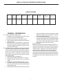
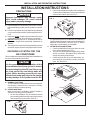
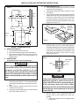
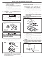
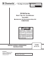
INSTALLATION AND OPERATING INSTRUCTIONS
RECORD THIS UNIT INFORMATION FOR
FUTURE REFERENCE:
Model Number
Serial Number
Date Purchased
B3300 Series
Roof Top Air Conditioner
Used With
Mechanical Air Distribution Box Kit
3309278.004
This manual must be read and understood before installation, adjustment, service, or maintenance
is performed. This unit must be installed by a qualified service technician. Modification of this product
can be extremely hazardous and
could result in personal injury or
property damage.
INSTALLATION & OPERATING
INSTRUCTIONS
REVISION:
Form No. 3308925.019 7/05
(Replaces 3308925.001)
©2005 Dometic Corporation
LaGrange, IN 46761
Important: These instructions must stay with
unit. Owner read carefully.
1
TYPE
B3351.531
INSTALLATION AND OPERATING INSTRUCTIONS
SAFETY INSTRUCTIONS
This manual has safety information and instructions to help users eliminate or reduce the risk of
accidents and injuries.
RECOGNIZE SAFETY INFORMATION
!
This is the safety-alert symbol. When you see this
symbol in this manual, be alert to the potential for
personal injury.
Follow recommended precautions and safe operating instructions.
UNDERSTAND SIGNAL WORDS
A signal word , WARNING OR CAUTION is used
with the safety-alert symbol. They give the level of
risk for potential injury.
! WARNING indicates a potentially hazardous situation which, if not avoided, could result in
death or serious injury.
! CAUTION indicates a potentially hazardous situation which, if not avoided may result in
minor or moderate injury.
CAUTION
used without the safety alert
symbol indicates, a potentially hazardous situation which, if not avoided may result in property
damage.
Read and follow all safety information and instructions.
2
INSTALLATION AND OPERATING INSTRUCTIONS
SPECIFICATIONS
TYPE
NO.
NOMINAL
CAPACITY
WATTS
COOLING
ELECTRICAL
RATING
COMPRESSOR
RATED LOAD
KW
COMPRESSOR
LOCKED
ROTOR
KW
FAN MOTOR
RATED LOAD
KW
FAN MOTOR
LOCKED
ROTOR
KW
REFRIGERANT
R-22
GRAMS/OZ
HEATER AMPS
AT
220 / 240 VAC
B3351.531
3,245
220 / 240 VAC,
50 HZ., 1PH.
1.1 / 1.2
4.5 / 5.0
0.21
0.46
510/18.0
1.64
giving it a "head start" on the expected high outdoor
ambient will greatly improve its ability to maintain
the desired indoor temperature.
7. For a more permanent solution to a high heat gain,
accessories like outdoor patio and window awnings
will reduce heat gain by removing the direct exposure to the sun. They also add a nice area to enjoy
company during the cool of the evening.
C. Condensation
Note: The manufacturer of this air conditioner will not be
responsible for damage caused by condensed moisture on
ceilings or other surfaces. Air contains moisture and this
moisture tends to condense on cold surfaces. When air
enters the RV, condensed moisture may appear on the
ceiling, windows, metal parts, etc. The air conditioner
removes this moisture from the air during normal operation.
Keeping doors and windows closed when this air conditioner
is in operation will minimize condensed moisture on cold
surfaces.
GENERAL INFORMATION
A. This air conditioner is designed for:
1. Installation on a recreational vehicle during or after
the time the vehicle is manufactured.
2. Mounting on the roof of a recreational vehicle.
3. Roof construction with rafters/joists on minimum of
400mm centers.
4. Minimum of 25mm and maximum of 100mm distance between roof to ceiling of recreational vehicle.
Alternate installation methods will allow for roofs
more than 100mm thick.
B. The ability of the air conditioner to maintain the desired
inside temperature depends on the heat gain of the RV.
Some preventative measures taken by the occupants of
the RV can reduce the heat gain and improve the
performance of the air conditioner. During extremely
high outdoor temperatures, the heat gain of the vehicle
may be reduced by:
1. Parking the RV in a shaded area
2. Using window shades (blinds and/or cur tains)
3. Keeping windows and doors shut or minimizing
usage
4. Avoiding the use of heat producing appli ances.
5. Operation on High Fan/Cooling mode will give optimum or maximum efficiency in high humidity or high
outside temperature.
6. Starting the air conditioner early in the morning and
3
INSTALLATION AND OPERATING INSTRUCTIONS
INSTALLATION INSTRUCTIONS
2. For two unit installations: Install one air conditioners
1/3 and one air conditioner 2/3's from front of RV and
centered from side to side. See FIG. 2.
PRECAUTIONS
! WARNING
Improper installation may damage equipment, could endanger life, cause serious
injury and/or property damage.
FIG. 2
L
2/3 L
1/3 L
A. Read installation and operating instructions carefully
before attempting to start your air conditioner installation.
B. Dometic Corporation will not be liable for any damages
or injury incurred due to failure in following these instructions.
C. Installation must comply with the National Electrical
Code and any Region or Local Codes or regulations.
D. DO NOT add any devices or accessories to this air
conditioner except those specifically authorized by
Dometic.
E. This equipment must be serviced by qualified personnel
and some regions require these people to be licensed.
It is preferred that this air conditioner be installed in a
relatively flat and level roof section measured with the RV
parked on a level surface; however, up to 15o slant to
either side, or front-to-back, is acceptable.
C. AFTER LOCATION SELECTION:
1. Check for obstructions in the area where air conditioner will be installed. See FIG. 4.
2. The roof must be designed to support 60 Kg. when
the RV is in motion. Normally a 90 Kg. static load
design will meet this requirement.
c. Check inside the RV for air box obstructions. (i.e.
door openings, room dividers, curtains, ceiling fixtures, etc.) See FIG. 3.
CHOOSING LOCATION FOR THE
AIR CONDITIONER
This air conditioner is specifically designed for installation on
the roof of a recreational vehicle (RV).
CAUTION
It is the responsibility of the installer of this
air conditioner/heat pump system to ensure
structural integrity of the RV roof. Never create a low spot on the roof where water will
collect. Water standing around the air conditioner/heat pump may leak into the interior
causing damage to the product and the RV.
FIG. 3
325mm
871mm
A. NORMAL LOCATIONS:
The air conditioner is designed to fit over an existing roof
vent opening. When the vent is removed, it normally
creates a 360mm x 360mm opening.
B. OTHER LOCATIONS:
When no roof vent is available or another location is
desired, the following is recommended:
1. For one unit installation: The air conditioner should
be mounted slightly forward of center (front to back)
and centered from side to side. See FIG. 1.
FIG. 1
1/2 L
750mm
510mm
570mm
60mm
L
4
INSTALLATION AND OPERATING INSTRUCTIONS
C. OPENING PREPARATION:
1. If the opening exceeds 365mm x 365mm, it will be
necessary to install spacers.
2. If the opening is less than 355mm x 355mm, it must
be enlarged.
3. The opening must be framed to provide adequate
support and prevent air from being drawn from the
roof cavity. Lumber 20mm thick or more and long
enough to bridge the opening must be used. Remember to provide an entrance hole for the power
supply wire. See FIG. 5.
FIG. 4
194mm
133
mm
360
mm
Rear
of
Unit
378
mm
194mm
20mm
Min.
460
mm
360mm x 360mm
Opening
Frame
Opening
Provide
Hole For
Wiring
75mm
Front
of
Unit
510mm
FIG. 5
75mm
285
mm
285
mm
4. In addition to the frame, the opening must be
reinforced with (10 mm or more thick) strips of
plywood at least 90mm wide around all 4 sides of the
cut out hole. This will help provide strength to accept
the wood screws needed to secure the air box. The
strips must be glued in place onto the ceiling
material. See FIG. 6.
ROOF PREPARATION
A. ROOF VENT REMOVAL:
1. Unscrew and remove the roof vent.
2. Remove all caulking compound around opening.
3. Seal all screw holes and seams where the roof
gasket will be located. Use a good grade of all
weather sealer.
B. NEW OPENING:
(Installations Other Than Vent Openings)
90mm
FIG. 6
360x 360mm
Cut Out
! WARNING
90mm
There may be electrical wiring between the
roof and the ceiling. Disconnect 220-240volt
AC power cord and the positive (+) 12 volt
DC terminal at the supply battery. Failure to
follow this instruction may create a shock
hazard causing death or severe personal injury.
90mm
90mm
CAUTION
It is the responsibility of the installer of this air
conditioner system to ensure structural integrity of the RV roof. Never create a low spot
on the roof where water will collect. Water
standing around the air conditioner may leak
into the interior causing damage to the product and the RV.
1. A 360mm x 360mm opening must be cut through the
roof and ceiling of the RV. It is recommended this
opening be located between roof reinforcing members.
2. Mark a 360mm x 360mm square on the roof and
carefully cut the opening.
3. Using the roof opening as a guide, cut the matching
hole in the ceiling. See FIG. 4.
5. Route a copper 1.5mm2 with ground, supply line
from the fuse or circuit breaker box to the roof
opening.
a. The power supply must be on a appropriately
fused circuit.
5
INSTALLATION AND OPERATING INSTRUCTIONS
b. Wiring must comply with all National, Region
and Local wiring codes.
c. Make sure at least 255mm of wire extends into
the roof opening. This insures easy air conditioner attachment.
d. If vent fan was removed, the existing wire may be
used provided it is of proper size and correctly
fused.
This completes the outside work. Minor adjustments can be
done from the inside if required.
DISCHARGE DUCT AND CEILING
TEMPLATE INSTALLATION
A. Remove air box and mounting hardware from carton. The
upper duct is shipped inside the lower duct which is part
of the ceiling template.
1. Remove upper duct from ceiling template and locate
it over blower discharge.
2. Use two (2) #10 x 10mm screws (C) to hold duct to
base pan. Holes are provided in bottom of basepan
for these screws.
Note: Edges without flanges install toward REAR and SIDE
of opening. See FIG. 9.
PLACING THE AIR CONDITIONER ON
THE ROOF
CAUTION
This unit weighs approximately 45 Kg. To
prevent back injury, use a mechanical hoist
to place air conditioner on roof.
FIG. 9
A. Remove the Air Conditioner from the carton and discard
the carton. See FIG. 7.
FIG. 7
Recycle All
Cardboard
B. Place the air conditioner on the roof.
B. Measure (See FIGS. 9 & 10) the ceiling to roof thickness:
1. If distance is 25-50mm, remove perforated tabs from
both upper and lower ducts.
2. If distance is 50-75mm , remove perforated tabs from
bottom duct only.
3. If distance is 75-100mm, install ducts as received.
C. Check for correct alignment and adjust the unit as
necessary (Roof Gasket centers over 360mm x 360mm
opening).
D. Reach up into return air opening of the air conditioner and
pull the unit electrical cord down for later connection.
See FIG. 10.
CAUTION
Do not slide the unit. This may damage the
neoprene gasket attached to the bottom and
create a leaky installation.
C. Lift and place the unit over the prepared opening using
the gasket as a guide. Seal under the gasket with silicon
sealant. The condenser coil goes toward
the rear of the RV. See FIG. 8.
FIG. 8
Lift And Place
CENTER A /C
FROM BEL OW
FIG. 10
Front
MEASURE
CEILING
THICKNESS
Do Not Slide
D.
GASKET
Place the Air Box Kit inside the RV. This box contains
mounting hardware for the air conditioner and will be
used inside the RV. See FIG. 7.
6
PULL DOW N
ELECTRICAL CORD
INSTALLATION AND OPERATING INSTRUCTIONS
E. Install ceiling template by sliding lower duct over upper
duct.
F. Start each mounting bolt by hand before tightening any
of them. The four (4) threaded inserts in the base pan can
be seen to aid in starting the bolts.
G. Use a battery drill and run all 4 bolts up until they touch
the template but are not tight.
H. With the ceiling template flat against the ceiling install
the 6 wood screws at an angle, so as to stretch and
flatten the template. Three across the front and 3 across
the back of the template. See FIG.. 11.
WIRING OF SYSTEM
Note: All wiring must comply with the National Electrical
Code and any Region or Local Codes or regulations.
(Steps A. - F refer to FIG. 13- FIG.14.)
! WARNING
Disconnect 220-240 volt AC. Failure to follow these instructions could create a shock
hazard causing death or severe personal
injury.
FIG. 11
Knobs
Wood
Screws
I.
EVENLY TIGHTEN THE 4 MOUNTING BOLTS TO A
TORQUE OF 4.5 to 5.7 Nm.
This will compress the roof gasket to approximately
10 mm. The bolts are self locking so over tightening is
not necessary. See FIG. 12.
FIG. 12
! WARNING
This product is equipped with a 3-wire
(grounded) system for protection against
shock hazard. Make sure that the appliance
is wired into a properly grounded AC circuit
and the polarity is correct. Failure to do so
could result in death, personal injury or damage to the equipment.
Evenly Tighten
The 4 Mounting
Bolts To 4.5 - 5.7
Nm
A.
B.
CAUTION
C.
If bolts are left loose there may not be an
adequate roof seal or if overtightened, damage may occur to the air conditioner base or
ceiling template. Tighten to torque specifications listed in this manual.
D.
7
Route supply line into junction box through provided
Connector. 150mm leads are sufficient for connection
to unit wires and ground screws.
Connect RED wire in junction box to RED wire from
supply line.
Connect BLACK wire in junction box to BLACK wire
from supply line.
Connect supply ground wire to identified ground screw
in junction box.
INSTALLATION AND OPERATING INSTRUCTIONS
E.
F.
Install junction box cover with two (2) #10 x 10mm blunt
point screws. See FIG. 14.
Plug air conditioners electrical cord into the mating
connector on control box.
E.
F.
INSTALL AIR BOX
A.
B.
Remove return air grille from air box by pulling in on halfround finger catches.
Hold air box up to ceiling template and install three (3)
#10 x 10mm screws at air box mounting point. See FIG.
15.
In the event that the wood screws used to hold the
plastic air box to the ceiling do not grip or strip in the
ceiling material, four ceiling hollow wall anchors can be
used.
Remove the plastic air box and drill 8mm diameter holes
in the location of the 4 screws. Install the hollow wall
anchors (not supplied and follow manufacturers hollow
wall anchor installation instructions). See FIG. 18.
FIG. 18
FIG. 15
Hollow Wall
Anchor
Ramset
HWD5M4
Hollow Wall Anchor
Compressed
Install 3 Screws In to
Metal Template
C.
G.
H.
Snap hole plug into place at rear of air box. See FIG. 16.
FIG. 16
Reinstall the plastic air box.
Place 2 wires on top of the foam filter pad from corner
to corner before placing the grill assembly into the air
box. Reinstall return air grille and filter into air box. See
FIG. 19.
FIG. 19
Wood
Screw
Place 2 Wires
From Corner To
Corner
Hole Plug
Wood
Screw
D.
Filter Grill
Install four (4) #8 x 16mm wood screws that hold air box
tight to ceiling. Hand tighten to prevent stripping of the
of the screw in the ceiling. Do Not Use a power screw
driver. See FIG. 16 & 17.
I.
FIG. 17
Do Not Use Power Screw Driver To
Tighten Wood Screws
8
The air conditioner installation is now complete. Turn on
power to the unit for operational check. Please read
Unit Operating Instructions before proceeding.
INSTALLATION AND OPERATING INSTRUCTIONS
OPERATING INSTRUCTIONS
FIG. 20
OFF
COOL
®
WARMER
FAN
HIGH
LOW
MED
MED
HIGH
LOW
LOW
HIGH
MED
HEAT
COOLER
CONTROLS
HEATING OPERATION
A. The Selector Switch has 10 positions including "OFF".
This controls fan speed, heating mode, and cooling
modes. See FIG. 20.
B. The Thermostat controls the temperature range from 18°
C on the coldest side to 32° C on the warmest side. In the
cooling mode, the compressor ON/OFF controlled by
the thermostat setting.
Note: This electric heater will not replace a furnace for
heating your RV in cold weather. The intent is to remove the
chill on cool days or mornings.
A. Turn the thermostat to the desired temperature setting.
B. Select the fan speed that best satisfies your needs:
1. HIGH HEAT: Selected when maximum heating
is required,
2. MEDIUM HEAT: Selected when normal or average
heating is required
3. LOW HEAT: Selected when room at desired comfort level and needs to be maintained.
COOLING OPERATION
A. Set the thermostat at the desired temperature level.
B. Select the fan speed that best satisfies your needs:
1. HIGH COOL: Selected when maximum cooling and
dehumidification required.
2. MED. COOL: Selected when normal or average
cooling required.
3. LOW COOL: Selected when room at desired
comfort level and needs to be maintained. Normally
this speed used for night time operation.
Note: The blower runs continuously to circulate air and
maintain an even temperature. The compressor will come on
as cooling is required to maintain the selected temperature
level.
FAN OPERATION
A. This will circulate the air in your RV without cooling or
heating. There are three positions: HIGH FAN, MED.
FAN or LOW FAN to select from, depending upon
personal choice.
"OFF" POSITION
A.
This is to turn Unit off.
MAINTENANCE
1.
4.
AIR FILTER:
Periodically remove the return air filter located above the
removable grille in the air box. Wash the filter with soap
and warm water, let dry and then reinstall.
Note: Never run the air conditioner without return air filter in
place. This may plug the unit evaporator coil with dirt and may
substantially affect the performance of the unit.
2.
3.
AIR BOX HOUSING:
Clean air box housing and control panel with a soft cloth
dampened with a mild detergent. Never use furniture
polish or scouring powders.
FAN MOTOR:
Factory lubricated and requires no service under normal
use.
9
FROST FORMATION ON COOLING COIL:
Under certain conditions, frost may form on the evaporator coil. If this should occur, inspect the filter and
clean if dirty. Make sure air louvers are not obstructed.
Air conditioners have a greater tendency to frost when
the outside temperature is relatively low. This may be
prevented by adjusting the thermostat control knob to a
warmer setting (counter clockwise). Should frosting
continue, operate on LOW, MED. or HIGH FAN setting
until the cooling coil is free of frost.
INSTALLATION AND OPERATING INSTRUCTIONS
SERVICE - Unit Does Not Operate
If your unit fails to operate or operated improperly, check
the following before calling your service center.
1.
2.
3.
4.
If RV connected to motor generator, check to be sure
motor generator is running and producing power.
If RV connected to power supply by a land line, check
to be sure line is sized properly to run air conditioner
load and it is plugged into power supply.
Check your fuse or circuit breaker to see if it is open.
After the above checks, call your local service center for
further help. This unit must serviced by qualified service
personnel only.
When calling for service, always give the air conditioner
Model Number and Serial Number. This information can
be found on unit rating plate located on the base pan
near the return air opening. Return air grille must be
removed from air box to view.
10
INSTALLATION AND OPERATING INSTRUCTIONS
MOUNTING PARTS
AIR CONDITIONING UNIT
FIG. 22
FIG. 21
Discharge Air
Opening
A. (4) 180mm mounting bolts
Mounting Bolt
B. (10)
#8 x 16mm long sharp point wood screws
Return Air
Opening
Threaded Hole
In Bottom
C. (7) #10 x 10mm blunt point tapping screws
Mounting Bolt
Upper Discharge
Duct
Power Supply
Line
D. (1) Connector
Framing Stock
E. (1) Hole Plug
Discharge Air
Duct
AIR BOX - CONTROLS
WIRING DIAGRAM
1
ROTARY
2
SWITCH
L1 C H
4
1
YEL
2
RED
3
ELEC
BLU
4
WHT
5
CONN
TO
GRN/YEL
1
GRN/YEL
BLK
GRY
1
2
3 PIN
TO ELEC
3
HEAT
9 PIN
A/C
3
RED
4
BLU
5
WHT
BOX
6
BRN
7
GRN/YEL
BLK
2
GRN/YEL
3
WHT
50 HZ 1 PH
USE COPPER
CONDUCTORS
ONLY
FIELD WIRING
FACTORY WIRING
LINE SPLICE
RED
COMPRESSOR
C
WHT
START
CAP
WHT
RUN
CAP
S
R
O.L.
ELECTRICAL BOX
LIMIT SWITCH
3 PIN
1
220/240 VAC
EARTH
JUNCTION
RED
WHT
6
RED
NEUTRAL(P)
2
YEL
2
PTCR
BRN
BLK
9 PIN
1
FAN
CAP
FAN
MOTOR
7
THERMOSTAT
3
ACTIVE(P)
GRN/YEL
ORN
BRN
GRY
AIR CONDITIONER - WIRING DIAGRAM
3309275.000
11
BLK
HEATING ELEMENT
3309270.001