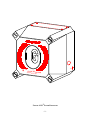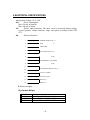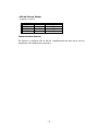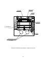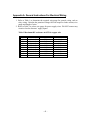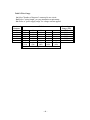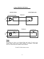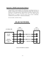
1
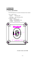
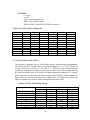
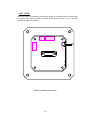
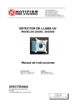
SharpEye 20/20I
3
Triple IR (IR )
Flame Detector
User's and Maintenance Manual
Doc. No. TM 20/20I, Rev. (4)-99 July 1999
Factory Mutual
CENELEC
C.S.A.
Approved
Approved
Approved
Class I Div. 1 Groups B, C, D
Class II Div. 1 Groups E, F, G
EExd IIB T5
EN 50-014, 50-018
Class I Div. 1 Groups B, C, D
Class II Div. 1 Groups E, F, G
Contents
CONTENTS ...................................................................................................................................................................... 2
FIGURES ........................................................................................................................................................................... 4
TABLES ............................................................................................................................................................................. 4
INTRODUCTION........................................................................................................................................................... 5
1 TECHNICAL FEATURES ........................................................................................................................................ 7
1.1 PRINCIPLES OF OPERATION..........................................................................................................................7
1.1.1 Hydrocarbon fire detection......................................................................................................................... 7
1.1.2 Identifying the CO2 peak ............................................................................................................................. 7
1.1.3 The limitations of IR-IR flame detectors ................................................................................................... 7
1.1.4 The advantages of IR3 technology.............................................................................................................. 8
2 PERFORMANCE.......................................................................................................................................................11
2.1 DETECTION SENSITIVITY.............................................................................................................................11
2.2 CONE OF VISION...............................................................................................................................................12
2.3 FALSE ALARM PREVENTION ......................................................................................................................13
3 OPERATION...............................................................................................................................................................14
3.1 VISUAL INDICATIONS....................................................................................................................................14
3.2 OUTPUT SIGNALS.............................................................................................................................................15
3.2.1 Optional latching:.......................................................................................................................................16
3.2.2 Built-In-Test .................................................................................................................................................16
3.2.3 ACCESSORY RELAY AS EOL ..................................................................................................................16
3.3 MODE SELECTION............................................................................................................................................16
3.3.1 Function switch (SW1):..............................................................................................................................16
3.3.2 Address switch (SW2) (Optional):...........................................................................................................17
3.3.3 Alarm Delay switch (SW3):.......................................................................................................................18
3.4 BUILT IN TEST ...................................................................................................................................................20
4 ELECTRICAL SPECIFICATIONS .....................................................................................................................22
5 MECHANICAL SPECIFICATIONS ...................................................................................................................25
6 ENVIRONMENTAL SPECIFICATIONS ..........................................................................................................26
7 INSTALLATION INSTRUCTIONS ....................................................................................................................28
7.1 SCOPE....................................................................................................................................................................28
7.2 GENERAL CONSIDERATIONS......................................................................................................................28
7.3 PREPARATIONS FOR INSTALLATION......................................................................................................29
7.4 CONDUIT INSTALLATION.............................................................................................................................29
7.5 DETECTOR MOUNTING..................................................................................................................................30
7.5.1 Swivel Mount Kit:.......................................................................................................................................30
7.5.2 Swivel installation (Figs. No. 7 and 8):..................................................................................................30
7.6 WIRING..................................................................................................................................................................33
7.7 TERMINAL WIRING..........................................................................................................................................33
7.8 MODE SELECTION............................................................................................................................................38
-2-
8 OPERATING INSTRUCTIONS............................................................................................................................39
8.1 SCOPE....................................................................................................................................................................39
8.2 POWER-UP ...........................................................................................................................................................39
8.3 RESET ....................................................................................................................................................................39
8.4 FUNCTIONAL TESTING..................................................................................................................................40
8.4.1 Manual BIT Test..........................................................................................................................................40
8.4.2 Testing with fire simulator........................................................................................................................40
8.5 SAFETY PRECAUTIONS.................................................................................................................................41
9 MAINTENANCE INSTRUCTIONS ....................................................................................................................42
9.1 SCOPE....................................................................................................................................................................42
9.2 MAINTENANCE INSTRUMENTATION AND PERSONNEL................................................................42
9.3 PREVENTIVE MAINTENANCE PROCEDURES .......................................................................................42
9.4 PERIODIC MAINTENANCE PROCEDURES..............................................................................................42
9.4.1 Power-Up Procedure..................................................................................................................................43
9.4.2 Functional Test Procedure........................................................................................................................43
9.5 MAINTENANCE RECORDS............................................................................................................................43
9.6 TROUBLESHOOTING.......................................................................................................................................43
9.6.1 Fault Indication...........................................................................................................................................43
9.6.2 False Alarm or Warning Indication ........................................................................................................43
APPENDIX A. GENERAL INSTRUCTIONS FOR ELECTRICAL WIRING...........................................45
APPENDIX B. TYPICAL WIRING CONFIGURATIONS ..............................................................................48
APPENDIX C. RS485 COMMUNICATION NETWORK................................................................................53
APPENDIX D. MOUNTING THE “DE” VERSION..........................................................................................55
3
APPENDIX E. LONG RANGE IR FIRE SIMULATOR.................................................................................60
-3-
Figures
FIGURE 1: IR 3 FLAME D ETECTOR....................................................................................... 9
FIGURE 2: FLAME D ETECTOR ASSEMBLY - OUTLINE DRAWING..................................... 10
FIGURE 3: HORIZONTAL AND VERTICAL FIELDS OF VIEW ............................................... 12
FIGURE 4: INDICATION LED S ............................................................................................ 14
FIGURE 5: SWITCH LOCATIONS ......................................................................................... 19
FIGURE 6: FLAME D ETECTOR ASSEMBLY - SCHEMATIC S ECTION .................................. 24
FIGURE 7: IR 3 D ETECTOR AND SWIVEL M OUNT ASSEMBLY........................................... 31
FIGURE 8: SWIVEL M OUNT ASSEMBLY - OUTLINE DRAWING ......................................... 32
FIGURE 9: TERMINAL BOARD ............................................................................................ 35
FIGURE 10: FLAME D ETECTOR ASSEMBLY - WIRING D IAGRAM..................................... 36
FIGURE 11: IR 3 FLAME D ETECTOR WITH COVER REMOVED ........................................... 37
FIGURE 12: FLAME D ETECTOR WIRING DIAGRAM .......................................................... 48
FIGURE 13: TYPICAL WIRING DIAGRAM FOR 4 WIRE CONTROLLER................................. 49
FIGURE 14: TYPICAL WIRING DIAGRAM FOR CONTROLLERS WITH ALARM & FAULT
LOOPS .......................................................................................................................... 50
FIGURE 15: 4-20 MA WIRING OPTIONS .............................................................................. 51
FIGURE 16: RS-485 NETWORKING..................................................................................... 53
FIGURE 17: FLAME D ETECTOR ASSEMBLY - WIRING D IAGRAM..................................... 57
FIGURE 18: FLAME D ETECTOR ASSEMBLY - WIRING D IAGRAM (“DE VERSION”) .......... 58
Tables
TABLE 2-1.1: ALARM RESPONSE TIME VERSUS RANGE ..................................................... 11
TABLE 2-3.1: I MMUNITY TO FALSE ALARM SOURCES ..................................................... 13
TABLE 2-3.2: WELDING I MMUNITY D ISTANCE ................................................................. 13
TABLE 3-2.1: O UTPUT SIGNALS VERSUS DETECTOR STATE ............................................ 15
TABLE 3-3.1: FUNCTION SWITCH SW1 ............................................................................. 17
TABLE 3-3.2: S ENSITIVITY RANGE..................................................................................... 17
TABLE 3-3.3: ADDRESS SWITCHES SW2............................................................................ 17
TABLE 3-3.4: SW2 ADDRESS SETTING SW2 ..................................................................... 18
TABLE 3-3.5: SW3 ALARM D ELAY S ETTING .................................................................... 18
TABLE 1:M AXIMUM DC RESISTANCE AT 68ºF FOR COPPER WIRE................................... 45
TABLE 2:WIRE GAUGE....................................................................................................... 46
-4-
Introduction
The Spectrex Model 20/20I is a triple IR spectrum flame detector designed to provide
maximum fire protection. It uses innovative technology of advanced digital signal
processing to analyze the dynamic characteristics of fire. Three sensitive IR channels
process the signals. Detection performance is controlled by a microprocessor and easily
adapted to all environments, applications and requirements. The result is a unique and
superior flame detector, which provides excellent detection sensitivity with extreme
immunity to false alarm. This manual consists of two parts. Part A describes the detector
and its features. Part B contains instructions on the installation, operation and
maintenance.
-5-
PART A
TECHNICAL MANUAL
-6-
1 TECHNICAL FEATURES
• DETECTION RANGE: up to 60 m (200 ft) for a 0.3m x 0.3m (1ft x 1ft) fire.
• ULTRA HIGH IMMUNITY TO FALSE ALARMS (see para. 2.3).
• ADVANCED DIGITAL PROCESSING OF THE DYNAMIC
CHARACTERISTICS OF FIRE: Flickering, Threshold correlation and Ratio.
THREE SEPARATE IR CHANNELS: B ETWEEN 3-5 MICRONS .
• FIELD PROGRAMMABLE SENSITIVITY: four ranges.
• TWO RESPONSE LEVELS: Warning & Detection.
• SOLAR BLIND
• MICROPROCESSOR BASED: Digital signal processing.
• BUILT IN TEST: Manual and Automatic (see para. 3.4).
• ELECTRICAL INTERFACE:
- Dry contact RELAYS.
- Communication network RS-485.
- 4-20 mA output.
• CERTIFICATION: Approved by F.M, CSA, CENELEC.
1.1 PRINCIPLES OF OPERATION
1.1.1 Hydrocarbon fire detection
The triple IR flame detector detects all conceivable types of hydrocarbon fires, i.e.
any fire, which emits CO2.
1.1.2 Identifying the CO2 peak
The hydrocarbon fire is characterized by a typical radiation emission. The CO2 peak
emits intense radiation in the spectral band between 4.2 µ - 4.5 µ and weaker
radiation intensity outside this spectral band.
1.1.3 The limitations of IR-IR flame detectors
CO2 in the atmosphere attenuates the radiation in this spectral band. (Absorption and
emission of radiation always occur in the same band.) As a result, the greater the
distance between the detector and the fire, the weaker the intensity of the radiation
reaching the detector (the CO2 attenuation increases). This phenomenon explains the
limitations of the existing IR-IR flame detectors in the market:
-7-
• Detection distance is restricted to 10 meters (33ft) only.
• Their immunity to false alarm sources is limited.
1.1.4 The advantages of IR3 technology
To overcome these limitations, Spectrex Inc. revised an innovative concept of
utilizing an additional detection channel. Three channels collect more data from the
environment, permitting more accurate analysis and better performance. After careful
investigation, three channels were selected which, when operating jointly, provide
optimal fire detection characteristics:
Channel 1: 4.2 µ - 4.6 µ
Fire - the CO2 peak.
Channel 2: 4.0 µ - 4.2 µ
Eliminates false alarms from high temperature sources.
Channel 3: 4.8 µ - 5.2 µ
Eliminates false alarms from flickering of background radiation.
Most IR sources, which create misleading IR alarm stimuli, including the sun,
incandescent and halogen lamps, electric arc discharges, electrical heaters, etc., do
not possess this unique spectral signature of fire. The IR sensors of the detector
respond only to flickering of radiation signals. The signals are compared to a
predetermined threshold. Processing of the results from the three IR channels is
performed by the board microprocessor. The result is a much greater detection
distance and a highly increased ability to distinguish between fire and false alarms.
This sophisticated technology surpasses all other existing flame detection techniques
on the market today. Further enhancement of this triple IR analysis enables the
accurate detection of a hidden or smoldering fire where the radiating flames are not
visible, but the emitted hot mass of CO2 gases is detected.
This unique flame analysis capability (patent pending) has been incorporated
into the Triple-IR fire detector manufactured by Spectrex, Inc. The result is a
unique flame detector, which does not produce false alarms and provides at the
same time detection over greatly increased distances.
-8-
IR
3
FLAME DE
TECTOR
IN T
WITH BU
ILT
EST
FIGURE 1: IR 3 FLAME D ETECTOR
-9-
ALARM LED
IR SENSOR
120
IR SENSOR
IR SOURCE
IR SOURCE
1
A
IR
3
FLAME DETECTOR
WITH BUILT IN TEST
1/4"-20UNC-2B
132
8
2
OR EARTH TERMINAL
THREAD FOR CONDUIT
3/4"-14NPT
OR M25x1.5P
0
2 PL.
1
IR SENSOR
3
POWER LED
108 (4 1/4")
1/4"-20UNC-2B
OR M6x1P
4 PL.
VIEW A
FIGURE 2: FLAME D ETECTOR ASSEMBLY - OUTLINE DRAWING
- 10 -
2 PERFORMANCE
2.1 DETECTION SENSITIVITY
Detection sensitivity is the detection distance for a specified size of fire and type of
fuel (“Standard Fire”) within a given time from the ignition of the fire.
Standard Fire:
A 0.3m x 0.3m (1ft x 1ft) Gasoline pan fire with max. wind speed of 2 m/sec (6.5
ft/sec).
Sensitivity Ranges:
The detector has four user selectable sensitivity ranges. For each range there are two
response levels.
1. WARNING (Pre-alarm)
2. ALARM
The detection distance, for the WARNING level, is approximately 10% higher than
the ALARM distance. Alarm response times for a “standard fire” at a specified range
are shown hereunder.
Table 2-1.1: Alarm response time versus range
SENSITIVITY
RANGE
m/(ft)
RESPONSE TIME
(Sec)
1
15/(50)
3
2
30/(100)
5
3
45/(150)
8
4
60/(200)
10
Other fuels
The detector will react to other types of fires as follows:
PAN FIRE SIZE : 0.3m x 0.3m (1ft x 1ft)
MAXIMUM WIND SPEED : 2 m/sec (6.5 ft/sec)
MAXIMUM RESPONSE TIME : 10 sec
TYPE OF FUEL
GASOLINE
N-HEPTANE
ALCOHOL 95%
JP4
KEROSENE
DIESEL FUEL
% OF MAX. DISTANCE AT EACH SENSITIVITY RANGE
100%
100%
75%
75%
75%
50%
- 11 -
2.2 CONE OF VISION
Horizontal: 90 °
Vertical: 90 °
RELATIVE RANGE AS A FUNCTION OF THE INCIDENCE ANGLE
RELATIVE RANGE
-10 deg
-20 deg
-30 deg
-35 deg
-40 deg
-45 deg
-50 deg
100%
10 deg
20 deg
90%
80%
30 deg
35 deg
70%
60%
-60 deg
50%
FIGURE 3: HORIZONTAL AND VERTICAL FIELDS OF VIEW
- 12 -
40 deg
45 deg
50 deg
60 deg
2.3 FALSE ALARM PREVENTION
The detector will not provide an alarm or a warning signal as a reaction to the
radiation sources specified below.
NOTES:
IAD = Immune at Any Distance.
All sources are chopped from 0 to 20 Hz.
Table 2-3.1: Immunity To False Alarm Sources
Radiation Source
Immunity Distance m (ft)
Sunlight
IAD
Indirect or reflected sunlight
IAD
Vehicle headlights (low beam) conforming to MS53023-1
IAD
Vehicle IR lights (low beam) conforming to MS53024-1
IAD
Incandescent frosted glass light, 100 W
IAD
Incandescent clear glass light, rough service, 100 W
IAD
Fluorescent light with white enamel reflector, standard office IAD
or shop, 40 W (or two 20 W)
Electric arc [12mm (15/32 in) gap at 4000 V alternating IAD
current, 60 Hz]
Arc welding [4 mm (5/32 in) rod; 240 A]
See Table 2-3.2
Ambient light extremes (darkness to bright light with snow, IAD
water, rain, desert glare and fog)
Bright colored clothing, including red and safety orange.
IAD
Electronic flash (180 watt-seconds minimum output)
IAD
Movie light, 625 W quartz DWY lamp (Sylvania S.G.-55 or 2 (6.5)
equivalent)
Red dome light conforming to MS51073-1
IAD
Blue-green dome light conforming to M251073-1
IAD
Flashlight (MX 991/U)
IAD
Radiation heater, 1500 W
IAD
Radiation heater, 1000 W with fan
IAD
Quartz lamp (1000 W)
3(10)
Mercury vapor lamp
IAD
Grinding metal
IAD
Lit cigar
0.3 (1)
Lit cigarette
0.3 (1)
Match, wood, stick including flare up
3 (10)
Table 2-3.2: Welding Immunity Distance
SW setting
1
2
3
4
Detection Range
15m (50ft)
30m (100ft)
45m (150ft)
60m (200ft)
- 13 -
Immunity Distance
>4m (13ft)
>6m (20ft)
>9m (30ft)
>12m (40ft)
3 OPERATION
3.1 VISUAL INDICATIONS
Two LED-indications are located in the detector front window:
i. Power LED (Yellow)
Normal
- the LED is ON
BIT failure - the LED blinks (4 Hz)
ii. Alarm LED (Red)
Normal - the LED is OFF
Warning - the LED blinks (2 Hz)
ALARM - the LED is ON
ALARM LED
POWER LED
IR
3
FLAME DETECTOR
WITH BUILT IN TEST
FIGURE 4: INDICATION LED S
- 14 -
3.2 OUTPUT SIGNALS
The detector controls the following outputs:
• Alarm relay
• Accessory relay
• Fault relay
• 4-20mA current output
• RS-485 communication
The detector can be in one of the following states.
NORMAL:
BIT:
WARNING:
ALARM:
LATCHED
ALARM:
FAULT:
The detector is functioning normally.
The detector performs a Built In Test.
The detector detected a fire and changed into its warning – pre-alarm state.
The detector detected a fire and changed into its fire alarm state.
The alarm outputs are latched due to the detection of a fire that has already
been extinguished. A fault is detected during a BIT sequence, or the power
supply is too low.
A fault is detected during a BIT sequence or the power supply is too low. In
each state the detector will activate different outputs as specified in table 32.1.
Table 3-2.1: Output Signals Versus Detector State
Detector
State
Normal
Warning
Alarm
Latch
SW-1 On
Fault
Sw1
Switches
Sw1-2 On
Sw1-2
Sw1-2 Off
Power
Led
On
On
Alarm
Led
Off
Blink
Alarm
Relay
Off
Off
Accessory
Relay
Off
On
Fault
Relay
On
On
4-20ma
Output
5 mA
10 mA
On
On
On
Blink
On
On
On
Off
On
On
On
Off
On
Off
On
Off
On
On
On
Off
15 mA
15 mA
15 mA
0 mA
The detector will be in its FAULT state until it has passed a successful BIT.
When SW1-2 is OFF, WARNING state is the same as the ALARM state.
The alarm outputs will be activated as long as the alarm conditions are present and
will stop approximately 5 seconds after the fire is no longer detected.
- 15 -
3.2.1 Optional latching:
The detector includes a latched alarm output capability, which operates according to
the DIP switch SW1-1 position. Upon the detection of a fire, the detection signal is
latched until manually reset (disconnecting the power supply or performing a manual
BIT). Latching affects the ALARM RELAY only.
3.2.2 Built-In-Test
Successful Manual BIT will activate the following outputs according to SW1
switches.
SW 1-4 ON
SW 1-5 ON &
SW 1-4 ON
SW 1-5 ON &
SW 1-4 OFF
The ALARM relay will be activated for 3 seconds. The 4-20mA output
will provide 15 mA for 3 seconds.
The ACCESSORY & ALARM relays will be activated for 3 seconds.
The 4-20mA output will provide 15 mA for 3 seconds.
The ACCESSORY relay will be activated for 3 seconds. The 4-20mA
output will provide 10 mA for 3 seconds.
3.2.3 ACCESSORY RELAY AS EOL
When SW1-8 is ON then the accessory relay is used as End of Line relay. In this
case, the accessory relay is active as long as the detector is not in its FAULT state.
NOTE: The detectors’ status is available through its RS-485 communication link.
3.3 MODE SELECTION
The detector has 3 DIP switches, which enable the user to adapt the detectors’
operation to specific applications:
• Function switch (SW1).
• Address switch (SW2).
• Alarm delay switch (SW3).
3.3.1 Function switch (SW1):
The user can select the desired mode of operation by means of this switch according
to table 3-3.1:
- 16 -
Table 3-3.1: Function Switch SW1
SW.
1
2
ON Position
Alarm latching - enabled
Accessory relay activated at warning level
3
4
Automatic & manual BIT
Successful manual BIT activates the Alarm
relay and the 4-20 mA output turns to 15
mA for approximately 3 seconds.
Successful manual BIT activates the
accessory relay and the 4-20 mA output
turns to 10 mA for approximately 3
seconds.
Sensitivity range
Sensitivity range.
Accessory relay is used as End Of Line.
5
6*
7*
8
OFF Position
Alarm latching - disabled
Accessory relay activated at detection
level (together with Alarm relay)
Manual BIT only
Successful manual BIT does not
activate the Alarm relay.
Successful manual BIT does not
activate the Accessory relay.
Sensitivity range.
Sensitivity range.
Accessory relay operates in accordance
with the settings of SW1.
* See Table 3-3.2 for sensitivity range setting.
Table 3-3.2: Sensitivity range
Sensitivity Range
1 (lowest)
2
3
4 (highest)
SW1-7
OFF
OFF
ON
ON
SW1-6
OFF
ON
OFF
ON
3.3.2 Address switch (SW2) (Optional):
The address switch provides 64 alternative addresses that can be used with the RS-485
communication link. See tables 3-3.3 and 3-3.4.
Table 3-3.3: Address Switches SW2
SWITCH
Description
1
Address bit 0 (LSB)
2
Address bit 1
3
Address bit 2
4
Address bit 3
5
Address bit 4
6
Address bit 5 (MSB)
- 17 -
LEGEND:
0 = OFF
1 = ON
LSB = Least Significant Bit
MSB = Most Significant Bit.
SWITCH SW2-7 and SWITCH SW2-8 are unused.
Table 3-3.4: SW2 Address Setting SW2
ADDRESS
0
1
2
3
4
5
.
.
.
62
63
SW2-6
OFF
OFF
OFF
OFF
OFF
OFF
SW2-5
OFF
OFF
OFF
OFF
OFF
OFF
SW2-4
OFF
OFF
OFF
OFF
OFF
OFF
.
.
SW2-3
OFF
OFF
OFF
OFF
ON
ON
SW2-2
OFF
OFF
ON
ON
OFF
OFF
SW2-1
OFF
ON
OFF
ON
OFF
ON
ON
ON
ON
ON
ON
ON
ON
ON
ON
ON
OFF
ON
3.3.3 Alarm Delay switch (SW3):
The detector is equipped with an Alarm Delay option, which provides programmable
time delays of 0 to 30 seconds with seven (7) fixed settings at: 0, 3, 5, 10, 15, 20, and 30
seconds, using SW3 switches 1-3. See table 3-3.5. When an Alarm (Detection) level
condition is encountered, the detector delays the execution of the Alarm output relay by
the specified period of time. The detector will then evaluate the condition for 3 seconds.
If the Alarm level is still present, the Alarm output will be activated. If this condition no
longer exists, the detector will return to its standby state. The Alarm delay option will
affect the output relay and the 4-20mA output but not the alarm LED.
Table 3-3.5: SW3 Alarm Delay Setting
Delay (seconds)
0
Anti Flare (see next page)
3
5
10
15
20
30
SW3 switches
3
2
OFF
OFF
OFF
OFF
OFF
ON
OFF
ON
ON
OFF
ON
OFF
ON
ON
ON
ON
4
-----------------
- 18 -
1
OFF
ON
OFF
ON
ON
ON
OFF
ON
ANTI FLARE
Anti Flare mode is selected to prevent false alarm in locations where fast flares may
be present. The Time delay for fire alarm in this mode is from 2.5 to 15 seconds
(mostly less than 10 seconds).
SW3
SW1
SW2
FIGURE 5: SWITCH LOCATIONS
- 19 -
3.4 BUILT IN TEST
A. General
The detectors’ Built In Test (BIT) checks the following:
• Electronics circuitry
• Sensors
• Window cleanness
The detector can be set to perform the BIT automatically and manually (SW1-3 =
ON) or manually only (SW1-3 = OFF).
B. Principles
If the result of a BIT is the same as the current status of the detector (NORMAL or
FAULT), the detector's status is unchanged. If the result of a BIT differs from the
current status of the detector, then a second BIT is executed after a delay of 0.5
seconds. If the result of the second BIT is the same as the previous BIT (and still
differs from the current status), the detectors’ status is changed. (From NORMAL to
FAULT or from FAULT to NORMAL).
NOTE:When in FAULT status the detector disables its outputs.
C. Manual BIT only (SW1-3 = OFF)
The BIT is initiated manually by momentarily connecting Terminal No. 3 with
Terminal No. 2. A successful manual BIT activates the following:
• FAULT relay is closed.
• ALARM relay is activated for 3 sec (SW1-4 = ON)
• ACCESSORY relay is activated for 3 sec (SW1-5 = ON)
• 4-20 mA OUTPUT current will be 15mA when SW1-4 = ON or 10mA when
SW1-5 = ON & SW1-4 = OFF.
Unsuccessful BIT activates the following:
• FAULT relay is released.
• 4-20 mA output indicates FAULT condition (0 mA).
• POWER LED (yellow) blinks (4 Hz).
NOTE: If SW1 switches 4 or 5 are in their "ON" position the ALARM and
ACCESSORY relays will be activated during a MANUAL BIT, therefore, automatic
extinguishing systems or any external devices that should not be activated during BIT
should be disconnected.
D. Automatic & Manual BIT (SW1-3 = ON)
Manual Bit
Functions as described in Para. 3.4.c. In the case of an unsuccessful BIT all outputs
will function as described in para. 3.4.c, but the BIT will be automatically executed
every 1 minute. This mode of operation will continue until two consecutive
- 20 -
successful BIT's that have been encountered. As a result, the detector will resume its
normal operation.
Automatic BIT
The detector automatically performs a BIT every 15 minutes. A successful BIT
sequence does not activate any indication:
A successful BIT does not activate any indicator.
The FAULT relay is CLOSED (NORMAL).
The POWER LED is ON (NORMAL).
An unsuccessful BIT sequence activates the following:
The FAULT relay
is opened.
4-20mA output
indicate FAULT (0 mA).
The POWER LED (yellow)
blinks (4 Hz).
BIT procedure
will be performed every 1 minute.
- 21 -
4 ELECTRICAL SPECIFICATIONS
1st.Operating Voltage: 18-32 VDC
2nd.
Power Consumption:
Max. 150 mA in Stand-by
Max. 200 mA in Alarm
3rd.
Electric input protection: The input circuit is protected against voltagereversed polarity, voltage transients, surges and spikes according to MIL-STD1275.
4th.
Electrical Interface:
1
POWER SUPPLY IN (+)
2
RTN
3
Manual BIT
(-)
4
FAULT RELAY (N.O.)
5
(N.O.)
6
7
ALARM RELAY (COMM.)
8
(N.O.)
9
ACCESSORY RELAY (N.O.)
10
11
4-20 mA (output)
12
4-20 mA (input)
13
RS-485 (+)
14
RS-485 (-)
E. Electrical outputs
Dry Contact Relays:
RELAY
ALARM
ACCESSORY
FAULT
Contact ratings
- SPDT 2A at 30VDC or 250 VAC
- N.O. SPST 2A at 30VDC or 250VAC.
- N.O. SPST 2A at 30VDC or 250VAC.
- 22 -
4-20 mA Current Output:
Terminals 11 and 12:
FAULT
NORMAL
WARNING
ALARM
< 2 mA
4 - 6 mA
9 - 11 mA
14 - 16 mA
( Typical 0)
( 5)
(10)
(15)
Communication Network:
The detector is equipped with an RS-485 communication link that can be used in
installations with computerized controllers.
- 23 -
REFLECTOR
IR SENSOR
WINDOW
HOUSING
P.C. BOARDS ASSY
COVER
THREADS FOR CONDUIT
3/4"-14NPT
FIGURE 6: FLAME D ETECTOR ASSEMBLY - SCHEMATIC S ECTION
- 24 -
5 MECHANICAL SPECIFICATIONS
1st.Enclosure
Aluminum enclosure, chromate coating and epoxy anamel finish.
St. St. 316 electromechanical and pasivation coating
2nd. Explosion proof
FM approval
Class I Div. 1 Groups B, C and D;
Class II Div. 1 Groups E, F and G.
Cenelec approval
EEXd II B + H2 T5
EEXde II B + H2 T5.
CSA approval
Class I Groups B, C and D;
Class II Groups E, F and G.
3rd. Water and dust tight
NEMA 250 type 6p.
IP 66 and IP 67
4th. Electronic Modules
Conformable coating.
5th. Electrical connection (two positions)
Standard 3/4"-14NPT conduit or M25 (ISO).
6th. Dimensions
Base : 132 cm x 132 cm (5.2 x 5.2 in)
Height: 120 cm (4.7 in)
7th. Weight
3.7 Kg (8.1 lbs) – Aluminum Alloy
6.5 Kg (14.3 lbs) – ST.ST 316
- 25 -
6 ENVIRONMENTAL SPECIFICATIONS
1st.High Temperature
Design to meet MIL-STD-810C, method 501.1 procedure II
Operating temperature:
+70 deg.C (+160 deg.F)
Optional operating temperature: +85 deg.C (+185 deg.F)
Storage temperature:
+85 deg.C (+185 deg.F)
2nd.
Low Temperature
Design to meet MIL-STD-810C, method 502.1, procedure I
Operating temperature:
-40 deg.C (-40 deg.F)
Storage temperature:
-55 deg.C (-65 deg.F)
3rd.
Humidity
Design to meet MIL-STD-810C, method 507.1, procedure IV
Relative humidity of up to 95% for the operational temperature range.
4th.
Salt Fog
Design to meet MIL-STD-810C, method 509.1, procedure I
Exposure to a 5% Salt Solution Fog for 48 hours.
E. Dust
Design to meet MIL-STD-810C, method 510.1, procedure I
Exposure to a dust concentration of 0.3 frames/cubic ft. at a velocity of 1750 fpm,
for 12 hours.
F. Vibration
Design to meet MIL-STD-810C, method 514.2, procedure VIII
Vibration at an acceleration of 1.1g within the frequency range of 5-30 Hz, and an
acceleration of 3g within the frequency range of 30-500 Hz.
G. Mechanical Shock
Design to meet MIL-STD-810C, method 516.2, procedure I
Mechanical Shock of 40g half-sin wave, for 11 msec.
- 26 -
PART B
TECHNICAL MANUAL
- 27 -
7 INSTALLATION INSTRUCTIONS
7.1 SCOPE
The "Spectrex" Model 20/20I is a self-contained Optical Flame Detector, designed to
operate as a stand alone unit directly connected to alarm systems or automatic fire
extinguishing systems. The detector can form part of a more complex system where
many detectors and other devices are integrated through a common control unit. This
chapter does not attempt to cover all of the standard practices and codes of
installation. Rather, it emphasizes specific points of consideration and provides some
general rules for qualified personnel. Wherever applicable, special safety precautions
are stressed.
7.2 GENERAL CONSIDERATIONS
Very Important:
The detector should be aimed toward the center of the detection zone and have a
completely unobstructed view of the protected area. Whenever possible, the detector
face should be tilted down at a slight angle to prevent the accumulation of dust and
dirt. Do not start an installation unless all conceivable considerations regarding
detector location have been taken into account. To ensure optimal performance and
an efficient installation, the following guidelines should be considered:
A. SENSITIVITY
To determine the level of sensitivity (SW1), the following issues should be
considered:
•
•
Size of fire at determined distance to be detected.
Type of flammable materials.
B. SPACING AND LOCATION
The number of detectors and their locations in the protected area are affected by:
•
Size of the protected area
•
Sensitivity of the detectors
•
Obstructed lines of sight
•
Cone of view of the detectors
- 28 -
C. ENVIRONMENT
•
Dust, snow or rain can reduce the detectors sensitivity and require more
maintenance activities.
•
The presence of high intensity flickering of IR sources may affect sensitivity.
7.3 PREPARATIONS FOR INSTALLATION
Installation should comply with NFPA 72E, as applicable to flame detectors. The
detectors can be installed with the use of general-purpose common tools and
equipment.
1 Verify the appropriate Purchase Order. Record the Part No. and the Serial
No. of the detectors and the installation date in the appropriate Log-book.
2 Open the container package immediately prior to detector installation and
visually inspect the detector.
3 Verify that all components required for the detector installation are readily
available before commencing the installation. In case that the installation is
not completed in a single session, secure and seal detectors and conduits.
4 For wiring, use color-coded conductors or suitable wire markings or labels.
12 to 20 AWG wires may be used for site wiring. The selection of wire
gauge should be based on the number of detectors used on the same line and
the distance from the control unit, in compliance with specifications (See
Appendix A).
7.4 CONDUIT INSTALLATION
1 To avoid water condensation water in the detector, it should be installed with
the conduits placed downward, and should include drain holes.
2 When using the optional swivel mount, use flexible conduits for the last
portion connecting to the detector.
3 For installations in atmospheres as defined in group B of the NFPA 72E,
conduits inlets should be sealed.
4 When pulling the cables through the conduits, ensure that they are not
tangled or stressed. Extend the cables about 30 cm. (12 in.) beyond the
detector location to accommodate wiring after installation.
5 After the conductor cables have been pulled through the conduits, perform a
continuity test.
- 29 -
7.5 DETECTOR MOUNTING
The detector may be mounted on a simple fabricated bracket, or preferably the
optional Swivel Mount, Model 20/20-003. The Swivel Mount enables the detector to
be rotated up to 40 degrees in all directions.
7.5.1 Swivel Mount Kit:
Mounting according to FM requirements:
ITEM
Swivel Mount
1/4"-20UNC Screw
1/4" Spring Washer
QTY
1
4
4
TYPE/MODEL LOCATION
20/20-003
1/4" –20UNC
Detector - Holding plate
1/4"
Detector - Holding plate
Mounting according to Cenelec requirements:
ITEM
Swivel Mount
Screw
Spring Washer
QTY
1
4
4
TYPE/MODEL LOCATION
20/20-003-1
M6 X 1P
Detector - Holding plate
M6
Detector - Holding plate
7.5.2 Swivel installation (Figs. No. 7 and 8):
1 Place the swivel mount (item 6) in its designated location and secure it with
four (4) M6 or 1/4" screws (item 11) (recommended), placed 76.2 mm. (3.0
in.) apart on the swivel mount plate (item 10).
Note: Skip this step if the Swivel Mount is already installed. Also detector
removal for maintenance purpose does not require Swivel Mount removal.
2 Unpack the detector.
3 Place the detector, with its conduit inlets pointing down, on the holding plate
of the swivel mount (item 7). Secure the detector by four (4) 1/4"-20UNC
screws with 1/4" spring washers from the Swivel Mount Kit (using the holes
(item 5)). Use 3/16 Hex Key for 1/4" screws and No. 5 for M6 screws.
4 Tighten the three locking 3/8"-24UNF screws (item 8) of the swivel mount
ring until the friction in the ball joint holds the detector in its position. Yet,
still permits it to be moved by hand-applied force (Use 3/16 " HEX KEY).
5 Point the detector towards the protected area and make certain that the view
of the area. Secure the detector in that position by tightening the locking
screws (item 8) of the swivel mount ring.
- 30 -
2
The detector is now correctly located and aligned and ready for connecting to the
system.
3
8
220
120
11
0
2
1
0
1
.
A
3
FLAME DETECTOR
0
WITH BUILT IN TEST
132
2
9
6
3
DIA 7
4 PL.
3
1
4
1
7
IR
76.2 (3")
100
108 (4 1/4")
VIEW A
FIGURE 7: IR 3 D ETECTOR AND SWIVEL M OUNT ASSEMBLY
- 31 -
0
6
1
5
7
.
0
DIA 7
4 PL.
76.2 (3")
100
5
0
VIEW A
6
7
1
8
10
A
FIGURE 8: SWIVEL M OUNT ASSEMBLY - OUTLINE DRAWING
##
1
2
##
7
8
Description
Holding Plate
Locking Screws
3
4
Description
Protective Set Screws
Ground Terminal (for CENELEC) or
Ground Thread (for FM)
Back Cover
Housing
9
10
5
6
Swivel Mount Screw Hole
Swivel Mount
11
Detector Mounting Screws
Swivel Mount Plate Securing Screws
Hole (4)
Swivel mounting screws
- 32 -
7.6 WIRING
1 Disconnect power.
2 Remove the four (4) protective set-screws from detector front. (Fig. 7 Item 1)
3 Refer to Fig. 11. Release the four (4) socket-head screws that secure the
detector housing (Item 1) to its back cover (Item 5) Using HEX KEY No. 5.
Hold the housing (Item 1) during the removal of the screws. With the screws
removed, pull the detector housing (Item 1) from its cover (Item 5). The cover
remains attached to the detector mount, the housing slides under the cover and
remains attached to it by a securing cable (Item 2). The Terminal Board inside
the detector cover is now revealed.
4 Remove the protective plug mounted on the detector conduit inlet, pull the
wires through the detector cover (Item 5) and secure them firmly to the cover
using the cable-clamp (Item 3) attached to it. Use a 3/4"-14NPT or M25x1.5
explosion-proof conduit connection to assemble the conduit to the detector.
5 Connect the wires to the required terminals (Item 4) according to the wiring
diagram. See paragraph 7.7 and figures no. 9 and no. 10.
6 Connect the grounding wire to the ground screw outside the detector cover (Fig.
7 item 2). The detector must be well grounded to EARTH GROUND for proper
operation.
7 Verify the wiring. Improper wiring may damage the detector.
8 Check the wires for secure mechanical connection and press them neatly against
the terminal board to prevent them from interfering while closing the detectors’
housing.
7.7 TERMINAL WIRING
The detector contains a Terminal Board consisting of two (2) terminal blocks (Item
4). The left terminal block is labeled 1 to 7, the right terminal block is labeled 8 to 14.
(See Fig. No.9 and No.10.)
The following describes the function of each electrical terminal of the detector:
Power Supply (Terminal Numbers 1, 2):
Input power is supplied to Terminal No. 1.
The RETURN is connected to Terminal No. 2.
Manual Bit Activation (Terminal No. 3):
Terminal No. 3 is used for the Manual BIT activation. The manual BIT is initiated by
a momentary connection of Terminal No. 3 to the power supply Return line.
Fault Relay (Terminal Numbers 4, 5):
The Fault output is N.O. SPST relay at Terminals No. 4 and 5. The contacts are
closed when the detector is in its normal operational condition.
- 33 -
Alarm Relay (Terminal Numbers 6, 7, 8):
The Alarm output is a change over contact relay (SPDT).
Terminal No. 6 is the N.O. relay contact.
Terminal No. 7 is the COMMON relay contact.
Terminal No. 8 is the N.C. relay contact.
Accessory Relay (Terminal Numbers 9, 10):
The Accessory output is N.O. SPST relay at Terminals No. 9 and 10.
The Accessory relay may act in parallel with the ALARM relay to activate another
external device or it may provide a warning signal, depending on the position of
SW1-2.
NOTE: To protect the dry contacts from voltage surges when connected to reactive
loads (electric motors, sirens, etc.) connect an appropriate varistor over these
contacts.
4-20 mA Output (Terminal Numbers 11, 12):
Terminal Numbers 11 and 12 are used for analog, 4-20 mA current output as
specified in paragraph 4.e
Terminal No. 11 is used as output Terminal (+).
Terminal No. 12 is used as input Terminal (-). (see appendix B for more details)
NOTE: For other ANALOG OUTPUTS consult the factory.
RS-485 (Terminal Numbers 13, 14):
Terminal Numbers 13 and 14 are used for communication network as specified in
appendix C.
Terminal No. 13 is the positive (+) lead.
Terminal No. 14 is the negative (-) lead.
- 34 -
7
5
14
13
9
1
6
4
11
3
10
2
1
12
8
5
I/O
BOARD
780052
9
SHIELD1
8
1
P1
P2
FIGURE 9: TERMINAL BOARD
- 35 -
1
POWER (+)
(18-32VDC)
2
RETURN (-)
3
MANUAL B.I.T. ACTIVATION
(N.O. MOM.)
4
FAULT RELAY CONTACTS
5
6
N.O.
7
COM.
8
N.C.
ALARM RELAY CONTACTS
9
ACCESSORY RELAY CONTACTS
10
11
4-20mA (OUTPUT)
12
4-20mA (INPUT)
13
R.S.-485 (+)
14
R.S.-485 (-)
SCREW
EARTH
GROUND
FIGURE 10: FLAME D ETECTOR ASSEMBLY - WIRING D IAGRAM
- 36 -
W
O
N
1 2 3 4 5 6 7 8
O
N
SW3
1 2 3 4
S
1
9
O
N
SW1
1 2 3 4 5 6 7 8
1
8
7
2
3
6
P2
P1
1
2
9
1
3
SHIELD1
8
I/O
BOARD
780052
1
4
6
5
4
8
10
9
11
7
14
13
12
5
5
FIGURE 11: IR 3 FLAME D ETECTOR WITH COVER REMOVED
##
1
2
3
4
5
Description
Housing
Securing Cable
Cable Clamp
Terminal Board
Back Cover
##
6
7
8
9
- 37 -
Description
Inlet Conduit
DIP Switch1
DIP Switch2
DIP Switch3
7.8 MODE SELECTION
When wiring is completed the operational mode can be selected.
Mode selection is achieved by means of 3 DIPswitches listed below:
SW1 - Function switch – Fig. 11 Item 7
SW2 - Address switch – Fig. 11 Item 8
SW3 - Alarm Delay switch – Fig. 11 Item 9
Function Switch (SW1):
Modes of operation are selected by DIPSwitch (SW1) (Item 7) according to the
selection table in paragraph 3.3.a.
Address Switch (SW2)
The detector has the capability of acting as an addressable device.
The address switch (Item 8) provides 64 addresses, which can be used by the RS-485
communications link as described in paragraph 3.3 b.
Alarm Delay Switch (SW3):
An Alarm Delay may be required for certain applications. The detector has an Alarm
Delay switch (SW3) (Item 9), permitting time delays from 0 to 3, 5, 10, 15, 20 and 30
seconds respectively (See table 3-3.5).
1 Function Switch (SW1): Set all eight (8) switches of SW1 to their appropriate
settings (ON/OFF), to achieve the required functional mode (See paragraph 3.3.a.).
2 Address Switch (SW2): Choose the address number from 0 to 63 for the detector
and set switches 1-6 according to the selection table at paragraph 3.3.b
NOTE: When a multi detector installation is used with RS-485 communication, then
each detector must have an individual address.
3 Alarm Signal Delay Switch (SW3): Set SW3 to the appropriate position to achieve
the required time delay. See paragraph 3.3.c.
4 a. Verify that the “o” Ring is in its groove in appropriate position on the back cover.
b. Close the detector; Connect the housing to the cover using the alignment pin on
the back cover. Tighten the four (4) socket-head screws to secure the detector
housing to its back cover tighting torge 1 Kg * M.
5 Install the four (4) set-screws that protect the socket-head screws.
The Detector is now wired, assembled and its operational mode properly set.
- 38 -
8 OPERATING INSTRUCTIONS
8.1 SCOPE
The following instructions are designed to obtain optimal performance from the
detector over its life cycle.
8.2 POWER-UP
1 Apply power and wait approximately 60 seconds for the automatic self-test of the
detector.
NOTE: Applying power initiates the following sequence:( POWER LED blinks BIT
is executed, if successful then: POWER LED turns ON continuously FAULT relay
contacts close)
2 Wiring Inspection: If a short-circuit or line discontinuity exists, indications will
appear on the control unit display panel. Review your wiring.
3 The detector goes into its FAULT state when supply voltage drops under 16.5V.
The detector status goes back to NORMAL, when the supply voltage is above
17.5V.
4 Detector Inspection: Visually inspects the viewing window of the detector. It should
be clean and clear. The POWER LED should be ON and the ALARM LED should
be OFF. The ALARM and ACCESSORY relays should be OFF and the FAULT
relay should be ON.
5 If any of the outputs or indications are different from the description in step 3, see
paragraph 9.6 for troubleshooting.
The Flame Detector is now ready for Functional Testing.
8.3 RESET
To RESET a detector when in its ALARM state, disconnect power (terminal No. 1 or
terminal No. 2), or initiate a manual BIT.
- 39 -
8.4 FUNCTIONAL TESTING
Following is a testing procedure for proper functioning of the detector.
8.4.1 Manual BIT Test
Important Note!
If SW1 switches 4 and 5 are in their “ON” position the Alarm and Accessory Relays
will be activated during a manual BIT, therefore, automatic extinguishing systems or
any external devices that may be activated during BIT must be disconnected.
1 Verify that the detector is operated properly.
2 Initiate manual BIT. After a few seconds the following occurs:
Alarm Relay will be activated and the 4-20 mA output turns to 15mA for 3 seconds
(only if SW1-4 is ON).
Accessory Relay will be activated and the 4-20 mA output turns to 10mA for 3
seconds (only if SW1-5 is ON).
The 2 leds should be ON.
Fault Relay will stay active during the test.
8.4.2 Testing with fire simulator
This test is produced to simulate an exposure of the detector to a real fire condition.
The detector is exposed to the radiation in the specified detection level. As a result
the detector must generate a Fire Alarm signal.
Important Note!
If the detector is exposed to a fire simulator and SW1 switches 4 or 5 are in their
“ON” position the Alarm and Accessory Relays and 4-20mA will be activated during
the simulation. Therefore, automatic extinguishing systems or any external devices
that may be activated during this process must be disconnected.
- 40 -
1 Apply power to the system and wait up to 60 seconds for turning of the detector to
normal state. Power led turns on. If the detector is on, skip this step.
2 Aim the Spectrex Fire Simulator Model 20/20-311 against the front of the viewing
window of the detector, in a way that the radiation emitted by it is facing directly
towards the detector. (See appendix E )
3 Press the operation button once. After few seconds the Alarm led should be on for
few seconds. The 4-20mA output should turn to 15 mA for approximately four (4)
seconds and then to return to 5 mA. The Alarm Relay should also turn on to this
period. The Accessory Relay should respond in parallel to the Alarm Relay if SW1-4
is off.
This completes the installation procedure. The detector and system are now ready for
operation.
8.5 SAFETY PRECAUTIONS
After Powering-up, the detector requires hardly any attention in order to function
properly, but the following should be noted:
1 Follow the instructions in the manual and refer to the drawings and specifications
issued by the manufacturer.
2 Do not expose the detector to radiation of any kind unless required for testing
purposes.
3 Do not open the detector housing, while power is supplied.
4 Do not touch internal parts other than the three functional switches. Interference
with internal circuits may impair detector performance and will invalidate
manufacturer's Warranty.
5 Disconnect external devices, such as automatic extinguishing systems before
carrying out any maintenance.
- 41 -
9 MAINTENANCE INSTRUCTIONS
9.1 SCOPE
This chapter deals with preventive maintenance, describes possible faults in detector
operation and indicates corrective measures. Ignoring these instructions may cause
problems with the detector and may invalidate the warranty. Whenever a unit requires
service, please contact the manufacturer or its authorized distributor for assistance.
9.2 MAINTENANCE INSTRUMENTATION AND PERSONNEL
The detectors’ maintenance requires ordinary tools and qualified personnel, who
should be familiar with local codes and practices.
9.3 PREVENTIVE MAINTENANCE PROCEDURES
The detector must be kept as clean as possible. The viewing window and the reflector
of the Model 20/20I Flame Detector must be cleaned on a periodic basis. The
frequency of cleaning operations depends upon the environmental conditions and
specific applications. The fire detection system designer will give his
recommendations. Use of the optional AIR SHIELD Model 20/20-920 is highly
recommended and will help to keep the window clean and prevent dirt from
accumulating on the window.
1 Disconnect power to the detector before proceeding with any maintenance including
lens cleaning.
2 To clean the detector viewing window and reflector use water and detergent, rinse
with clean water.
3 Where dust, dirt or moisture accumulates on the window, first clean with a soft
optical cloth and detergent, then rinse with clean water.
9.4 PERIODIC MAINTENANCE PROCEDURES
In addition to preventive cleaning and maintenance, the detector should be
functionally tested every six months. This test should also be carried out for any
reason the detector has been opened.
- 42 -
9.4.1 Power-Up Procedure
Perform Power-Up procedure every time power is restored to the system. Follow the
instructions in paragraph 8.2 above.
9.4.2 Functional Test Procedure
Perform a functional test of the detector as described in paragraph 8.4 above.
9.5 MAINTENANCE RECORDS
It is recommended to record maintenance operations performed on a detector in the
system Log-book. The record should include information which identifies the unit, the
installation date, contractor, and entries for every maintenance operation performed
including the description of the operation, date and personnel ID. If a unit is sent to
the manufacturer or distributor for service, a copy of the Maintenance records should
accompany it.
9.6 TROUBLESHOOTING
9.6.1 Fault Indication
1 Check power supply for correct voltage, polarity and wiring.
2 Check detector window and reflector for cleanness. If necessary clean the window
as indicated in paragraph 9.3, above and repeat the test.
3 Disconnect the power supply to the system and check the detector's internal wiring.
4 Reconnect power supply and wait approximately 60 seconds. Repeat the test. If the
indication LED is still blinking, the unit requires service.
9.6.2 False Alarm or Warning Indication
1 Disconnect the power supply from the system and check internal wiring.
2 Reconnect power supply and wait approximately 60 seconds. If indication remains,
the unit requires service.
- 43 -
APPENDIX A
Wire Selection Tables
- 44 -
Appendix A. General Instructions For Electrical Wiring
1. Refer to Table 1 to determine the required wire gauge for general wiring, such as
relay wiring. Calculate the permitted voltage fall with respect to loads current, wire
gauge and length of wires.
2. Refer to Table 2 to select wire gauge for power supply wires. DO NOT connect any
circuit or load to detectors’ supply inputs.
Table 1:Maximum DC resistance at 68ºF for copper wire
AWG #
26
24
22
20
18
16
14
12
10
Mm
0.12 - 0.15
0.16 - 0.24
0.30 - 0.38
0.51 - 0.61
0.81 - 0.96
1.22 - 1.43
1.94 - 2.28
3.09 - 3.40
4.56 - 6.64
Ohm per 100 ft.
4.32
3.42
1.71
1.07
0.67
0.43
0.27
0.17
0.11
- 45 -
Ohm/100 meter
14.15
11.22
5.60
3.50
2.20
1.40
0.88
0.55
0.35
Table 2:Wire Gauge
1st.Select "Number of detectors" connected in one circuit.
2nd. Select "wiring length" per your installation requirements.
3rd. Refer to "power supply range" for voltage extreme applied.
Number of
Detectors
24
20
16
12
8
4
AWG #
18
18
20
20
20
20
50
(164)
16
14
16
14
18
16
14
18
16
14
18
16
14
18
16
16
100
150
200
(328)
(492)
(656)
Wire length in meters (ft)
- 46 -
14
250
(820)
Power Supply
Range (Vdc)
22-32
22-32
22-32
22-32
22-32
18-32
APPENDIX B
TYPICAL WIRING CONFIGURATIONS
- 47 -
Appendix B. Typical Wiring Configurations
1
POWER (+)
(18-32VDC)
2
RETURN (-)
3
MANUAL B.I.T. ACTIVATION
(N.O. MOM.)
4
FAULT RELAY CONTACTS
5
6
N.O.
7
COM.
8
N.C.
ALARM RELAY CONTACTS
9
ACCESSORY RELAY CONTACTS
10
11
4-20mA (OUTPUT)
12
4-20mA (INPUT)
13
R.S.-485 (+)
14
R.S.-485 (-)
SCREW
EARTH
GROUND
FIGURE 12: FLAME D ETECTOR WIRING DIAGRAM
- 48 -
Typical Wiring Diagram for 4 Wire Controller
Controller
Power
Supply
Alarm
Loop
First
Detector
Last
Detector
Terminal
Terminal
Block
Block
+
1
1
-
2
2
6
6
7
7
4
5
FIGURE 13: TYPICAL WIRING DIAGRAM FOR 4 WIRE CONTROLLER
- 49 -
EOL
TYPICAL WIRING DIAGRAM FOR CONTROLLERS
WITH ALARM AND FAULT LOOPS
CONTROLLER
FIRST
LAST
DETECTOR
DETECTOR
MANUAL
BIT
3
3
1
1
-
2
2
ALARM
6
6
LOOP
7
7
FAULT
4
LOOP
5
POWER
+
SUPPLY
EOL
RESISTOR
4
5
EOL
RESISTOR
9
10
Notes:
1. FOR EOL RESISTORS VALUES SEE CONTROLLER MANUAL
2. THE ACCESSORY RELAY IN THE LAST DETECTOR SHOULD BE
CONFIGURED AS AN EOL (SWITCH SW1-8 “ON”)
FIGURE 14: TYPICAL WIRING DIAGRAM FOR CONTROLLERS WITH ALARM & FAULT
LOOPS
- 50 -
4-20mA WIRING OPTIONS
DETECTOR
ISOLATED DETECTOR
4-20mA : IN
CONTROLLER
TERMINALS
CONTROLLER
12
+
DET
ELEC.
SUPPLY
18-32V
CURRENT SOURCE
18 - 35V
MA
4-20mA : OUT
11
0.1-0.8K
NON-ISOLATED DETECTOR
TERMINALS
CONTROLLER
MA
4-20mA : OUT
DETECTOR
SUPPLY
18-32V
DET
ELEC.
11
CURRENT SOURCE
4-20mA : IN
0.1-0.8K
2
Notes:
The detectors are factory set to isolated 4-20mA sink version. To work at nonisolated 4-20mA version (source), connect Terminal 12 to Terminal 1. The 4-20mA
meter are connected between Terminal 11 and Terminal 2.
FIGURE 15: 4-20 MA WIRING OPTIONS
- 51 -
APPENDIX C
RS485 COMMUNICATION NETWORK
- 52 -
Appendix C. RS485 Communication Network
Using the RS485 network capability of the IR3 detector and additional software it is
possible to connect up to 32 detectors in an addressable system with 4 wires only (2
for power & 2 for communication). Using repeaters, the number of detectors can be
much larger (32 detectors for each repeater) on the same 4 wires. When using the
RS485 network it is possible to read each detector status (FAULT, WARNING,
ALARM) and to initiate a BIT to each detector individually.
Fore more details, consult the factory.
RS-485 NETWORK
FIRST
LAST
DETECTOR
DETECTOR
+
1
1
-
2
2
+
RS-485
COMPUTER
PORT
13
13
14
14
CONTROLLER
POWER
SUPPLY
FIGURE 16: RS-485 NETWORKING
- 53 -
APPENDIX D
Mounting the “de” version
- 54 -
Appendix D. Mounting the “de” version
1 DETECTOR MOUNTING
The detector may be mounted on a simple fabricated bracket, or preferably the
optional Swivel Mount, Model 20/20-003. The Swivel Mount enables the detector to
be rotated up to 40 degrees in all directions.
1.1 Swivel Mount Kit
Use the kit from the paragraph 7.5.1
1.2 Swivel installation
1 Refer to Fig.7 and Fig 8. Place the swivel mount (item 6) in its designated location
and secure it with four (4) M6 or 1/4" screws (item 11) (recommended), placed 76.2
mm. (3.0 in.) apart on the swivel mount plate (item 10).
Note: Skip this step if the Swivel Mount is already installed. Also detector removal
for maintenance purpose does not require Swivel Mount removal.
2 Unpack the detector.
3 Place the detector, with its conduit inlets pointing down, on the holding plate of the
swivel mount (Fig. 7 item 7). Secure the detector by four (4) 1/4"-20UNC screws
with 1/4" spring washers from the Swivel Mount Kit (using the holes (Fig. 8 item
5)). You can use the thread on the modified cover (Fig. 17 item 1) marked either
or .Use 3/16 Hex Key for 1/4" screws and No. 5 for M6 screws.
4 Tighten the three locking 3/8"-24UNF screws (Fig. 8 item 8) of the swivel mount
ring until the friction in the ball joint holds the detector in its position. Yet, still
permits it to be moved by hand-applied force (Use 3/16" HEX KEY).
5 Point the detector towards the protected area and make certain that the view of the
area. Secure the detector in that position by tightening the locking screws (Fig.8
item 8) of the swivel mount ring.
The detector is now correctly located and aligned and ready for connecting to the
system.
- 55 -
2 WIRING
Refer to Fig. 17.
1 Disconnect power.
2 Release the four (4) sloted-head screws that secure the chamber cover (Item 2). The
chamber is now revealed.
3 Remove the protective plug mounted on the detector conduit inlet, pull the wires
through the detector chamber (Item 7). Use a 3/4"-14NPT or M25x1.5 explosion-proof
conduit connection to assemble the conduit to the detector.
4 Connect the wires to the required terminals (Item 4) according to the wiring diagram.
See paragraph 2.1 and figures no. 17 and no. 18.
5 Connect the grounding wire to the ground screw outside the detector cover (Item 5).
The detector must be well grounded to EARTH GROUND for proper operation.
6 Verify the wiring. Improper wiring may damage the detector.
7 Check the wires for secure mechanical connection and press them neatly against the
terminal to prevent them from interfering while closing the cover (Item 2).
8 Place and secure the cover chamber using four (4) slotted screws (Item 3).
2.1 TERMINAL WIRING
The detector contains a chamber consisting of a terminal block (Item 4). The terminal
block is labeled 1 to 6. (See Fig. No.17.)
The following describes the function of each electrical terminal of the detector:
Power Supply (Terminal Numbers 1, 2):
Input power is supplied to Terminal No. 1.
The RETURN is connected to Terminal No. 2.
RS-485 (Terminal Numbers 3, 4):
Terminal Numbers 3 and 4 are used for communication network as specified in
appendix C.
Terminal No. 3 is the positive (+) lead.
Terminal No. 4 is the negative (-) lead.
4-20 mA Output (Terminal Numbers 5, 6):
Terminal Numbers 5 and 6 are used for analog, 4-20 mA current output as specified
in paragraph 4.e
Terminal No. 5 is used as output Terminal (+).
Terminal No. 6 is used as input Terminal (-). (see appendix B for more details)
NOTE: For other ANALOG OUTPUTS consult the factory.
- 56 -
112200
1
1
A
1
3
IR
3
FLAME DETECTOR
1
3
4
5
6
4
+
2
2
+
DDOO
5
+
+
WWIITTHH BBUUIILLTT IINN TTEESSTT
113322
8
1
1
7
6
110088((44 11//44""))
11//44""--2200UUNNCC--22BB
OORR MM66xx11PP
88 PPLL..
VVIIEEWW AA
FIGURE 17: FLAME D ETECTOR ASSEMBLY - WIRING D IAGRAM
Modified Back Cover
Chamber Cover
Slotted Screw
Terminal Block
##
5
6
7
8
Description
Ground Terminal
Mounting Thread
Chamber
Conduit Inlet
9
Description
3
##
1
2
3
4
- 57 -
1
POWER (+)
(18-32VDC)
2
RETURN (-)
3
R.S.-485 (+)
4
R.S.-485 (-)
5
4-20mA (OUTPUT)
6
4-20mA (INPUT)
SCREW
EARTH
GROUND
FIGURE 18: FLAME D ETECTOR ASSEMBLY - WIRING D IAGRAM (“DE VERSION”)
- 58 -
APPENDIX E
Long Range IR3 Fire Simulator
- 59 -
Appendix E. Long Range IR3 Fire Simulator
Product Description
The SharpEye IR3 Long-Range Fire simulator # 20/20-310 is designed specifically
for use with the IR3 flame detectors. The Fire Simulator emits IR radiation in a
unique sequential pattern corresponding and recognizable by the IR3 detector as fire.
This allows the IR3 detectors to be tested under real fire conditions without the
associated risks of an open flame. There is a specially designed beam collimator
model number 20/20-190 used for extended range.
Unpacking
In addition to the delivery form, there should be the following contents:
•
•
•
Fire Simulator with built in batteries
Battery charger
Optional Beam Collimator
Operating Instructions
Warning:
Do not open the Fire Simulator to charge the batteries or for any other reason in a
hazardous area.
Caution:
The following test will simulate a real fire condition and may activate the
extinguishing system or other alarms. If this is not desired, disconnect them before the
test and reconnect after the simulation.
- 60 -
Follow these instructions to simulate a fire:
1. Aim the Fire Simulator towards the detector.
Target Point
IR 3 FLAME DETECTOR
WWIITTHH BBUUIILLTT IINN TTEESSTT
2. Press the operation button once. Fire simulation will last for 15 seconds. The
detector will send an alarm signal (solid red LED).
3. For another fire simulation a 30 second time lapse is required between tests.
4. Make sure the optical window is clean and keep the Fire Simulator in a safe place
when not in use.
Battery Charging
The Fire Simulator uses NiCd batteries as a rechargeable power source. When the
batteries are fully charged it will operate for at least 100 uses without recharging. An
internal buzzer is sounded when the voltage from the batteries is lower than the
required operational level.
1. Place the Fire Simulator on a table in a safe area.
2. Turn the sealed plug (next to the operation button) counter-clockwise with a
suitable wrench.
3. Connect the battery charger.
4. Charge for a maximum of 14 hours.
5. Disconnect the charger.
6. Tighten the sealed plug clockwise.
Note: When the Fire Simulator is being charged operation is disconnected for safety.
- 61 -
Specifications
Mechanical
Explosion Proof Enclosure:
NFPA (designed to meet)
Class I, Division 1 & 2 Groups B, C and D
Class II, Division 1 & 2 Groups E, F, and G
CENELEC (approved by Nemko No. Ex 96D424)
En 50-014 & EN50-018
Eex d IIB T5, IP67
Electrical
Power:
9 VDC Max.
6 Rechargeable 1.2 VDC NiCd Batteries
Current: 2.5A Avg.
Charge 400mA for 14 Hours
Environmental
Temperature Range: -4o to 140o F
(-20o to 60o C)
Shock Protection:
1g (10-50hz)
Physical
Dimensions: 11 x 10.1 x 3.9 in (292 x 258 x 100 mm)
Weight:
7.5 lb. (3.4 Kg) )
Range*
Sensitivity
50 ft (15 m)
100 ft (30 m)
150 ft (45 m)
200 ft (60 m)
Standard
3.8 ft (1.2 m)
7 ft (2.2 m)
10 ft (3.2 m)
14.5 ft (4.5 m)
Extended Range
7 ft (2.2 m)
14.5 ft (4.5 m)
22 ft (7.0 m)
29 ft (9 m)
* At extreme temperatures 15% Max. Reduction
- 62 -
For further details or assistance, contact:
GasTech Australia Pty Ltd
106 Westpoint Centre
Osborne Park 6017
Tel: 1800 999 902 Int: 61 8 9242 1869
Fax: 1800 999 903 Int: 61 8 9242 1959
Your Local Authorized Distributor:
- 63 -