1
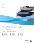
Setup Guide
Read This First
Trademarks.............................................................................................................3
Safety Information .................................................................................................4
Positions of RWARNING and RCAUTION labels ..............................................8
ENERGY STAR Program .......................................................................................9
Manuals for This Printer......................................................................................10
How to Read This Manual ...................................................................................11
Guide to the Printer
Exterior ................................................................................................................. 12
Inside.....................................................................................................................14
Control Panel........................................................................................................15
Setting Up
Where to Put the Printer......................................................................................17
Unpacking the Printer and Checking the Contents of the Box .......................20
Installing the Toner Cartridge.............................................................................22
Loading Paper ...................................................................................................... 26
Turning the Power On .........................................................................................29
Selecting the Display Language.........................................................................30
Test Printing .........................................................................................................32
G1168605A_1.10 EN USA G116-8604A
Copyright © 2004, 2005
1
Installing Options
Available Options.................................................................................................34
Option Installation Flow Chart ..................................................................................34
Installing Options...................................................................................................... 35
Attaching Paper Feed Unit Type 610..................................................................38
Attaching Envelope Feeder Type 610 ................................................................41
Attaching Memory Unit Type C 256MB (SDRAM Module)................................43
Attaching 1394 Interface Unit Type 4510 ........................................................... 48
Attaching 802.11b Interface Unit Type F............................................................ 54
Attaching Bluetooth Interface Unit Type C........................................................61
Attaching Hard Disk Drive Type 2600 ................................................................68
Attaching Network Data Protection Unit Type B...............................................70
Attaching Duplex Unit AD610 .............................................................................72
Connecting the Printer
Network Connection ............................................................................................75
USB Connection...................................................................................................77
Parallel Connection .............................................................................................78
IEEE 1394 Connection .........................................................................................79
Configuration
Ethernet Configuration........................................................................................80
IEEE 802.11b (Wireless LAN) Configuration .....................................................85
IEEE 1394 Configuration .....................................................................................91
IP over 1394.............................................................................................................91
SCSI print.................................................................................................................93
Installing the Printer Driver
Quick Install..........................................................................................................95
Install the Operating Instructions.......................................................................97
2
Read This First
Trademarks
Microsoft, Windows and Windows NT are registered trademarks of Microsoft
Corporation in the United States and/or other countries.
IPS-PRINT Printer Language Emulation Copyright© 1999-2000 Oak Technology, Inc., All rights reserved.
Bluetooth® is a registered trademark of Bluetooth-SIG Inc. worldwide.
Other product names used herein are for identification purposes only and might
be trademarks of their respective companies. We disclaim any and all rights to
those marks.
The proper names of the Windows operating systems are as follows:
• Microsoft® Windows® 95 operating system
• Microsoft® Windows® 98 operating system
• Microsoft® Windows® Millennium Edition (Windows Me)
• The product names of Windows® 2000 are as follows:
Microsoft® Windows® 2000 Advanced Server
Microsoft® Windows® 2000 Server
Microsoft® Windows® 2000 Professional
• The product names of Windows® XP are as follows:
Microsoft® Windows® XP Professional
Microsoft® Windows® XP Home Edition
• The product names of Windows ServerTM 2003 are as follows:
Microsoft® Windows ServerTM 2003 Standard Edition
Microsoft® Windows ServerTM 2003 Enterprise Edition
Microsoft® Windows ServerTM 2003 Web Edition
• The product names of Windows NT® 4.0 are as follows:
Microsoft® Windows NT® Server 4.0
Microsoft® Windows NT® Workstation 4.0
G1168605A_1.10
Copyright © 2004, 2005
3
Read This First
Safety Information
When using your printer, the following safety precautions should always be followed.
In this manual, the following important symbols are used:
Indicates a potentially hazardous situation which, if instructions are not followed, could result in
death or serious injury.
Indicates a potentially hazardous situation which, if instructions are not followed, may result in
minor or moderate injury or damage to property.
4
Read This First
• Confirm the wall outlet is near the machine and freely accessible, so
that in the event of emergency, it can be unplugged easily.
• Only connect the machine to the power source described in the manual.
• Avoid multi-wiring.
• Do not damage, break or make any modifications to the power cord.
Do not place heavy objects on it, pull it hard or bend it more than necessary. These actions could cause an electric shock or fire.
• Do not incinerate spilled toner or used toner. Toner dust is flammable
and might ignite when exposed to an open flame.
• Disposal should take place at an authorized dealer or an appropriate
collection site.
• If you dispose of the used toner cartridges yourself, dispose of them
according to local regulations.
• Do not store toner, used toner, or toner containers in a place with an
open flame. The toner might ignite and cause burns or a fire.
• Plug and unplug the power cord with dry hands, or an electric shock
could occur.
• Do not risk electric shock by handling the power cord or plug with wet
hands.
• Do not remove any covers or screws other than those specified in this
manual. Some parts of the machine are at a high voltage and could
give you an electric shock. Also, if the machine has laser systems, direct (or indirect) reflected eye contact with the laser beam may cause
serious eye damage. When the machine needs to be checked, adjusted, or repaired, contact your service representative.
• Do not take apart or attempt any modifications to this machine. There
is a risk of fire, electric shock, explosion or loss of sight. If the machine has laser systems, there is a risk of serious eye damage.
• Be sure to turn off the power switch and wait for about 15 minutes before cleaning the Registration roller. Not waiting for the printer to cool
down can result in a burn.
• Keep the machine away from flammable liquids, gases, and aerosols.
A fire or an electric shock might occur.
5
Read This First
• Do not handle the plug with wet hands. Doing so might cause an electrical
shock.
• Keep the machine in an area that is within optimum environmental conditions. Operating the machine in an environment that is outside the recommended ranges of humidity and temperature can cause an electrical fire
hazard. Keep the area around the socket free of dust. Accumulated dust
can become an electrical fire hazard.
• Place the machine on a strong and level surface. Otherwise, it might fall and
injure someone.
• If you use the machine in a confined space, ensure there is continuous air
circulation.
• Keep toner (used or unused) and the toner containers out of reach of children.
• If toner or used toner is inhaled, gargle with plenty of water and move into
a fresh air environment. Consult a doctor if necessary.
• If your skin comes into contact with toner or used toner, wash the affected
area thoroughly with soap and water.
• If toner or used toner gets into your eyes, flush immediately with large
amounts of water. Consult a doctor if necessary.
• If toner or used toner is swallowed, dilute by drinking a large amount of water. Consult a doctor if necessary.
• Avoid getting toner on your clothes or skin when removing a paper jam or
replacing toner. If your skin comes into contact with toner, wash the affected
area thoroughly with soap and water.
• If toner gets on your clothing, wash with cold water. Hot water will set the
toner into the fabric and may make removing the stain impossible.
• Our products are engineered to meet the highest standards of quality and
functionality. When purchasing expendable supplies, we recommend using
only those provided by an authorized dealer.
• Do not pull out the paper tray forcefully. If you do, the tray might fall and
cause an injury.
6
Read This First
• Before installing options, the machine should be turned off and unplugged
for at least an hour. Components inside the machine become very hot, and
can cause a burn if touched.
• Before moving the machine, unplug the power cord from the outlet. If the
cable is unplugged abruptly, it could become damaged. Damaged plugs or
cables can cause an electrical or fire hazard.
• When lifting the machine, use the grips on both sides. The machine could
break or cause an injury if dropped.
• The printer weighs about 20 kg (44.1 lb.).When lifting the machine, use the
inset grips on both sides. Otherwise the printer could break or cause injury
if dropped.
• Do not touch the inside of the controller board compartment. Doing so may
cause a malfunction or a burn.
• The inside of this printer becomes very hot. Do not touch parts labelled “v”
(indicating a hot surface). Touching these parts will result in burns.
• Grip the plug, not the cord, when pulling the plug from the socket. Pulling
the cord causes wear and tear that can result in fire or electric shock.
• Lifting the paper feed unit carelessly or dropping it may cause injury.
• When removing misfed paper, do not touch the fusing section because it
becomes very hot.
• When you move the printer, remember to unplug the power cord from the
wall outlet to avoid a fire or an electric shock.
• When you pull out the plug from the socket, grip the plug, not the cord, to
avoid damaging the cord and causing a fire or an electric shock.
• When moving the printer after use, do not take out any of the Toners, Photo
Conductor Units, nor the Waste Toner Bottle to prevent toner spill inside the
machine.
7
Read This First
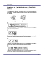
Positions of RWARNING and RCAUTION
labels
This machine has labels for RWARNING and RCAUTION at the positions
shown below. For safety, please follow the instructions and handle the machine
as indicated.
Do not incinerate toner or toner containers. Toner dust may cause flashback
when exposed to open flames.
The inside of this printer becomes very hot. Do not touch parts with this label (indicating a hot surface). Touching these parts will result in burns.
The inside of this printer becomes very hot. Do not touch parts with this label (indicating a hot surface). Touching these parts will result in burns.
The inside of this printer becomes very hot. Do not touch parts with this label(indicating a hot surface). Touching these parts will result in burns.
8
Read This First
ENERGY STAR Program
As an ENERGY STAR Partner, we have determined that this machine model meets the ENERGY STAR Guidelines for energy efficiency.
The ENERGY STAR Guidelines intend to establish an international energy-saving system for
developing and introducing energy-efficient office equipment to deal with environmental issues,
such as global warming.
When a product meets the ENERGY STAR Guidelines for energy efficiency, the Partner shall
place the ENERGY STAR logo onto the machine model.
This product was designed to reduce the environmental impact associated with office equipment by means of energy-saving features, such as Low-power mode.
❖ Low-power Mode (Energy Saver mode)
This printer automatically lowers its power consumption 30 minutes after the
last operation has been completed. To exit Low-power (Energy Saver) mode,
press any key on the control panel. For more information about how to configure Energy Saver mode, see “Making Printer Settings with Control Panel”,
Software Guide as a HTML file on the CD-ROM.
❖ Specifications
Energy Saver mode
Power Consumption
With Options: 9 W or less
Printer Only: 5.5 W
Default Time
- Recycled
30 minutes
Paper
In accordance with the ENERGY STAR Program, we recommend use of recycled paper which is environment friendly. Please contact your sales representative for recommended paper.
9
Read This First
Manuals for This Printer
For particular functions, see the relevant parts of the manual.
❖ Setup Guide (this manual)
Provides information about printer setup and options.
❖ Maintenance Guide
Provides information about paper, replacing supplies, and dealing with paper
jams and error messages.
❖ Software Guide (HTML)
Provides basic information about installing the printer driver and software, using the printer in a network environment, and configuration and setup.
Also, provides information about configuring and monitoring printer status using software and a Web browser.
❒ Some functions cannot be used depending on your printer.
10
Read This First
How to Read This Manual
The following set of symbols is used in this manual.
This symbol indicates a potentially hazardous situation that might result in death
or serious injury when you misuse the machine without following the instructions
under this symbol. Be sure to read the instructions, all of which are described in
the Safety Information section.
This symbol indicates a potentially hazardous situation that might result in minor
or moderate injury or property damage that does not involve personal injury
when you misuse the machine without following the instructions under this symbol. Be sure to read the instructions, all of which are described in the Safety Information section.
* The statements above are notes for your safety.
If this instruction is not followed, paper might be misfed, originals might be damaged, or data might be lost. Be sure to read this.
This symbol indicates information or preparations required prior to operating.
This symbol indicates precautions for operation, or actions to take after abnormal
operation.
This symbol indicates numerical limits, functions that cannot be used together,
or conditions in which a particular function cannot be used.
This symbol indicates a reference.
[]
Keys that appear on the machine's display.
Keys and buttons that appear on the computer's display.
{}
Keys built into the machine's control panel.
Keys on the computer's keyboard.
11
Guide to the Printer
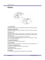
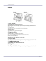
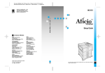
Exterior
1. Paper Size Dial
Adjust this dial to match the size and feed direction of the paper loaded in the paper tray.
2. Bypass Tray Extension
Pull out this extension to load paper into the Bypass Tray when its length is longer than
A4 L or 81/2” × 11”L.
3. Bypass Tray
Use to print onto thick paper, OHP transparencies, adhesive labels, custom size paper,
envelopes as well as plain paper. When printing on custom paper size, printer driver settings are required.
Up to 100 sheets of plain paper (80 g/m2, 20 lb.) can be loaded.
See “Paper and Other Media Supported by this Printer” and “Loading Paper in the Bypass Tray”, Maintenance Guide.
4. Output Tray Extension
Pull out this extension when printing on long paper.
5. Control Panel
Contains keys for the printer operation and a panel display that shows the printer status.
6. Output Tray (Standard Tray)
Printed output is stacked here with the print side facing down.
7. Paper Exit Cover
Open this cover to remove misfed paper.
8. Ventilator
This hole helps to keep components inside the printer from overheating.
G1168605A_1.10
Copyright © 2004, 2005
12
Guide to the Printer
❒ Do not block or obstruct the ventilator. A malfunction may occur due to overheating.
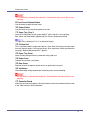
9. Front Cover Release Button
Use this button to open the front cover.
10. Power Switch
Use this switch to turn the printer power on and off.
11. Paper Tray (Tray 1)
Loads up to 500 sheets of plain paper (80 g/m2, 20 lb.) into this tray for printing.
See “Paper and Other Media Supported by this Printer”, Maintenance Guide.
❒ Paper Tray is displayed “Tray 1” on the panel display.
12. Friction Pad
This is required to feed in paper one sheet at a time. Clean the friction pad when more
than one sheet of paper is fed into the printer. Also, replace the friction pad when the
message, “Replace Maintenance Kit”, appears.
13. Paper Tray Cover
Attach it when pulling out the tray extension of the paper tray.
14. Power Cord
Connect this cord into a wall outlet.
15. Rear Cover
Remove to install the optional duplex unit or to replace the fusing unit.
16. Ventilators
These holes help to keep components inside the printer from overheating.
❒ Do not block or obstruct the ventilators. A malfunction may occur due to overheating.
17. Controller Board
Slide it out to install some options. Attach the interface cable, the network interface cable
or the 1394 interface cable to the board.
13
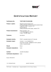
Guide to the Printer
Inside
1. Toner Cartridge
Includes toner and a photo conductor unit.
When “Replace Toner Cartridge” appears on the panel display, replace this unit.
2. Front Cover
Open this cover when accessing the inside of the printer.
3. Guide Board
Open this board to remove misfed paper.
4. Registration Roller
Feeds the paper. If it becomes dirty, clean it.
See “Cleaning the Registration Roller”, Maintenance Guide.
5. Transfer Roller Cover
Open this cover when replacing a transfer roller.
6. Transfer Roller
When “Replace Maintenance Kit” appears on the panel display, replace this roller.
7. Fusing Unit Lock Levers
Lift these levers when replacing the fusing unit.
8. Fusing Unit
Fuses the image onto paper.
When “Replace Maintenance Kit” appears on the panel display, replace this unit.
14
Guide to the Printer
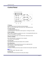
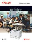
Control Panel
1. Display
Shows the current status of the printer and error messages.
See “Error & Status Messages on the Control Panel”, Maintenance Guide.
2. Power indicator
Is on while the printer power is on.
Is off when the power is turned off or while the printer is in Energy Saver mode.
3. Alert indicator
Blinks or lights up whenever any printer error occurs. A message describing the cause
of the error also appears on the display.
See “Error & Status Messages on the Control Panel”, Maintenance Guide.
4. Data In indicator
Blinks while the printer is receiving data from a computer.
Is on if there is data to be printed.
5. {Online} key
Press this key to switch the printer between online and offline.
6. {Job Reset} key
When the printer is online, press this key to cancel any ongoing print job.
See “Canceling a Print job”, Software Guide.
7. {Form Feed} key
If the printer is offline, press this key to print all the data left in the printer's input buffer.
❒ This does not work if the printer is online.
8. {Menu} key
Press this key to make and check the current printer settings.
15
Guide to the Printer
See “Making Printer Settings Using the Control Panel”, Software Guide.
9. {Escape} key
Press this key to return to the previous condition on the display.
10. {# Enter} key
Press this key to execute menu items selected on the display.
Press this key to clear some errors.
See “Troubleshooting”, Maintenance Guide.
11. {U} {T} keys
Use these keys to increase or decrease values on the display when making settings.
Keep the key pressed to quicken scrolling, and increase or decrease values on the display in units of 10.
16
Setting Up
Where to Put the Printer
The printer's location should be carefully chosen because environmental conditions greatly affect its performance.
• Confirm the wall outlet is near the machine and freely accessible, so
that in the event of emergency, it can be unplugged easily.
• Only connect the machine to the power source described in the manual.
• Avoid multi-wiring.
• Do not damage, break or make any modifications to the power cord.
Do not place heavy objects on it, pull it hard or bend it more than necessary. These actions could cause an electric shock or fire.
• Do not handle the plug with wet hands. Doing so might cause an electrical
shock.
• Keep the machine in an area that is within optimum environmental conditions. Operating the machine in an environment that is outside the recommended ranges of humidity and temperature can cause an electrical fire
hazard. Keep the area around the socket free of dust. Accumulated dust
can become an electrical fire hazard.
• Place the machine on a strong and level surface. Otherwise, it might fall and
injure someone.
• If you use the machine in a confined space, ensure there is continuous air
circulation.
❖ Space Required for Installation
Leave enough space around the printer. This space is necessary to operate
the printer. The recommended (or minimum) space requirements are as follows:
A: 10 cm (4 inches) or more
G1168605A_1.10
Copyright © 2004, 2005
17
Setting Up
B: 10 cm (4 inches) or more
C: 100 cm (39.4 inches) or more
D: 10 cm (4 inches) or more
❖ Optimum Environmental Conditions
Permissible and recommended temperature and humidity ranges are as follows:
• White area: Permissible Range
• Gray area: Recommended Range
❒ The machine must be level within 5 mm, 0.2” from both front to rear and left
to right.
❒ To avoid possible build-up of ozone, locate this machine in a large well ventilated room that has an air turnover of more than 30 m3/hr/person.
❒ When you use this machine for a long time in a confined space without
good ventilation, you may detect an odd smell. To keep the workplace
comfortable, we recommend you keep it well ventilated.
❖ Environments to Avoid
❒ Areas exposed to direct sunlight or strong light
❒ Dusty areas
18
Setting Up
❒
❒
❒
❒
❒
Areas with corrosive gases
Areas that are excessively cold, hot, or humid
Locations near air conditioners or humidifiers
Locations near other electronic equipment
Locations subject to frequent strong vibration
❖ Power Source
Connect the power cable to a power source of the following specification:
• 120 V, 60 Hz, 8.4 A or more
19
Setting Up
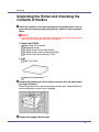
Unpacking the Printer and Checking the
Contents of the Box
A Check the contents of the box according to the following list. If one or
some items are missing, please contact your sales or service representative.
❒ The interface cable is not included in the box. Make sure that the interface
cable you use, is appropriate for your computer.
❖ Manuals and CD-ROMs
Setup Guide (This manual)
Maintenance Guide
CD-ROM “Printer Drivers and Utilities”
CD-ROM “Display-Version Manuals (HTML)”
CD-ROM “Print-Version Manuals (PDF)”
❖ Parts
Paper Tray Cover
Additional Documentation
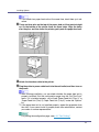
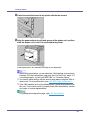
B Remove the plastic bag. Lift the printer and move it to the place where
you want to install it.
When lifting the machine, use the inset grips on both sides. Otherwise the machine could break or cause injury if dropped.
C Remove the orange adhesive tape.
20
Setting Up
❒ Lower the machine slowly and carefully to prevent trapping your hands.
21
Setting Up
Installing the Toner Cartridge
The following procedure describes how to install the toner cartridge.
• Do not incinerate spilled toner or used toner. Toner dust is flammable
and might ignite when exposed to an open flame.
• Disposal should take place at an authorized dealer or an appropriate
collection site.
• If you dispose of the used toner cartridges yourself, dispose of them
according to local regulations.
• Do not store toner, used toner, or toner containers in a place with an
open flame. The toner might ignite and cause burns or a fire.
• Keep toner (used or unused) and the toner containers out of reach of children.
• If toner or used toner is inhaled, gargle with plenty of water and move into
a fresh air environment. Consult a doctor if necessary.
• If your skin comes into contact with toner or used toner, wash the affected
area thoroughly with soap and water.
• If toner or used toner gets into your eyes, flush immediately with large
amounts of water. Consult a doctor if necessary.
• If toner or used toner is swallowed, dilute by drinking a large amount of water. Consult a doctor if necessary.
• Avoid getting toner on your clothes or skin when removing a paper jam or
replacing toner. If your skin comes into contact with toner, wash the affected
area thoroughly with soap and water.
• If toner gets on your clothing, wash with cold water. Hot water will set the
toner into the fabric and may make removing the stain impossible.
• Our products are engineered to meet the highest standards of quality and
functionality. When purchasing expendable supplies, we recommend using
only those provided by an authorized dealer.
❒ Do not expose the toner cartridge to a light for a long time. If you do, the toner
will be damaged and the printing quality might be reduced.
22
Setting Up
❒ The toner cartridges that comes with the printer will allow you to print up to
about 3,000 pages. These numbers were obtained from printing A4 K5%
charts, but the actual number of pages will vary depending on the paper type,
size, contents, and settings.
❒ Toner cartridges (consumable) are not covered by warranty. However, if there
is problem, contact the store where they ware purchased.
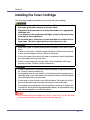
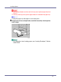
A Open the front cover by pushing the front cover release button.
B Remove the fixing material inserted between toner cartridge and the
printer.
C Lift the front side of the toner cartridge, and then pull it out of the printer.
23
Setting Up
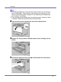
❒ Do not hold the toner cartridge upside down or stand it vertically.
❒ Do not put the toner cartridge on an unstable or tilted surface.
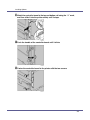
D Place the toner cartridge on a flat surface. Pull out the tape inside the
unit horizontally while holding the cartridge with one hand as shown in
the illustration.
❒ Be sure to remove the tape completely before installing the toner cartridge.
Otherwise, the printer might be damaged.
❒ If you pull out the strips when the toner cartridge is slant or standing on its
side, the cartridge might cause trouble with the printer.
❒ Be sure to pull the tape horizontally. Pulling it upward or downward may
cause the toner to scatter.
❒ After pulling the tape out of the cartridge, toner scatters easily. Do not
shake the cartridge.
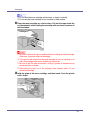
E Hold the grips of the toner cartridge, and then insert it into the printer
until it stops.
24
Setting Up
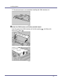
F Insert the toner cartridge in its appropriate position by gently pushing
down.
G Close the front cover by pressing the indentations on the left and right
sides.
❒ Do not close the front cover with force. If you cannot close the cover easily,
pull out the toner cartridge from the printer and insert it again. After that,
close the front cover again.
❒ Dispose of removed fixing material and tape in the same manner as ordinary plastic waste.
25
Setting Up
Loading Paper
The following describes how to load paper into the standard paper tray (Tray 1).
• Do not pull out the paper tray forcefully. If you do, the tray might fall and
cause an injury.
❒ To avoid paper jams, make sure paper is not stacked above the limit mark inside the tray. Misfeeds might occur.
❒ Do not mix different types of paper in a single paper tray.
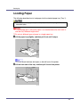
A Lift the paper tray slightly, and then pull it out until it stops.
❒ Do not touch the three white pins on the left front of the printer.
B Lift the front side of the tray, and then pull it out of the printer.
26
Setting Up
C Load the new paper into paper tray with print side up.
❒ Confirm that the top of the stack is not higher than the limit mark inside the
tray.
❒ Confirm that the paper fits under the rear guides.
❒ When loading paper other than A4L(long-edged feed) or 81/2 × 11L(longedged feed), adjust the paper size dial to match the size and feed direction
of the paper in the paper tray.
❒ When loading paper other than A4K(short-edged feed) or 81/2 ×
11K(short-edged feed), you should extend the tray.
27
Setting Up
D Carefully slide the paper tray into the printer until it stops.
❒ Confirm that the setting of the paper size dial matches the sizes and feed
direction of the paper in the tray. Otherwise, the printer might be damaged
or a printing problem might occur.
❒ Do not slide the paper tray in and out with force. If you do, the front and
side paper guides will move out of the place.
For details about usable types of paper, see “Loading Paper”, Maintenance
Guide.
28
Setting Up
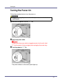
Turning the Power On
Follow the procedure below to turn the power on.
• Plug and unplug the power cable with dry hands, or an electric shock
could occur.
A Make sure the power is set to “b” Off.
B Plug in the power cable.
❒ Make sure the power cable is plugged securely into the wall outlet.
❒ Turn the power off when plugging and unplugging the power plug.
C Turn the power to “a” On.
The power indicator on the control panel lights up.
29
Setting Up
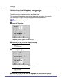
Selecting the Display Language
Select a language using the procedure described here.
The message for the selected language will appear on the display. If you want to
use the display in English, the following procedures are unnecessary.
❒ The default setting is English.
A Press the {Menu} key.
The [Menu] screen appears on the display.
B Press the {U} or {T} key to display [Language].
Menu:
Language
C Press the {# Enter} key.
The following message appears on the display:
Language:
*English
D Press the {U} or {T} key until the language you want to select appears.
30
Setting Up
E Press the {# Enter} key. Wait for two seconds.
The [Menu] screen appears on the display.
F Press the {Online} key.
The initial screen appears.
Ready
31
Setting Up
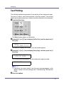
Test Printing
The following explains the procedure for test printing of the configuration page.
Test print in order to verify that the printer is working normally. Test printing
checks printer performance only; it does not test the connection to the computer.
A Press the {Menu} key.
The [Menu] screen appears on the display.
B Press the {U} or {T} key to display [List/Test Print], and then press the {#
Enter} key.
Menu:
List/Test Print
The menu for selecting the contents to be test printed appears.
C Press the {U} or {T} key to display [Config. Page], and then press the {#
Enter} key.
List/Test Print
Config. Page
The following message appears and the configuration page is printed.
Printing...
❒ If printing is not normal, check to see if an error message appears on the
display. If there is an error message, see “Troubleshooting”, Maintenance
Guide.
D Check the options.
32
Setting Up
❒ For details about the configuration page, see “Interpreting the Configuration Page”, Software Guide.
E Press the {Online} key.
The initial screen appears.
Ready
33
Installing Options
Available Options
This section describes how to install options.
By installing options, you can improve the printer performance and have an expanded variety of features to use. For the specifications of each option, see
Maintenance Guide.
• Before installing options, the machine should be turned off and unplugged
for at least an hour. Components inside the machine become very hot, and
can cause a burn if touched.
• Before moving the machine, unplug the power cable from the outlet. If the
cable is unplugged abruptly, it could become damaged. Damaged plugs or
cables can cause an electrical or fire hazard.
• When lifting the machine, use the grips on both sides. The machine could
break or cause an injury if dropped.
❒ The voltage rating of the connector for options is 24 V DC or less.
Option Installation Flow Chart
We recommend you install multiple options in the following order:
A Attach the paper feed unit (Paper Feed Unit Type 610).
Attach the paper feed unit to the bottom of the printer.
You can attach up to two paper feed unit. Up to 1600 sheets of paper can be
loaded.
B Attach the envelope feeder (Envelope Feeder Type 610).
Replace the paper tray of the optional feeder with the envelope feeder.
C Install the SDRAM module (Memory Unit Type C 256MB).
Install the module to the SDRAM module slot on the controller board.
D Install the 1394 interface unit, 802.11b interface unit or Bluetooth interface unit.
Install the 1394 interface unit, 802.11b interface unit or Bluetooth interface
unit on the controller board.
The 1394 interface unit, IEEE 802.11b interface unit or Bluetooth interface
unit cannot be used at the same time.
One of the following can be installed:
• 1394 Interface Unit Type 4510
G1168605A_1.10
Copyright © 2004, 2005
34
Installing Options
• 802.11b Interface Unit Type F
• Bluetooth Interface Unit Type C
E Install the hard disk drive (Hard Disk Drive Type 2600).
Install the hard disk drive to the controller board.
F Install the Network Data Protection Unit Type B.
Insert the network data protection unit into the SD card slot on the controller
board.
G Attach the duplex unit (Duplex Unit AD610).
Attach the duplex unit to the rear of the printer.
Installing Options
Install options in the positions shown in the illustration.
❖ Exterior
1. Paper Feed Unit Type 610 (Tray 2 or Tray 3)
You can load up to 500 sheets (60-105 g/m2, 16-28 lb.) of plain paper into the tray.
See p.38 “Attaching Paper Feed Unit Type 610”.
❒ A maximum two paper feed units Type 610 can be attached.
❒ Top-most optional paper feed unit is displayed “Tray 2” and bottom-most is displayed “Tray 3” on the display.
2. Envelope Feeder Type 610
You can load up to 60 envelopes (72-90 g/m2, 19-24 lb.) into the tray.
See p.41 “Attaching Envelope Feeder Type 610”.
35
Installing Options
❒ The envelope feeder is a tray that slides into the optional paper feed unit. Without
the optional paper feed unit, the envelope feeder cannot be used.
❒ Your printer can accommodate two optional paper feed units. The envelope Feeder unit can be used in “Tray 2”. Neither the main unit's feed tray (Tray 1) nor Tray
3 can be used for this purpose.
3. Duplex Unit AD610 (duplex unit)
You can print on both sides of paper.
Install the duplex unit by removing the rear cover of the printer.
See p.72 “Attaching Duplex Unit AD610”.
❖ Interior
1. 802.11b Interface Unit Type F
See p.54 “Attaching 802.11b Interface Unit Type F”.
2. 1394 Interface Unit Type 4510
See p.48 “Attaching 1394 Interface Unit Type 4510”.
3. Bluetooth Interface Unit Type C
See p.61 “Attaching Bluetooth Interface Unit Type C”.
4. Memory Unit Type C 256MB (SDRAM module)
See p.43 “Attaching Memory Unit Type C 256MB (SDRAM Module)”.
5. Network Data Protection Unit Type B
See p.70 “Attaching Network Data Protection Unit Type B”.
6. Hard Disk Drive Type 2600
See p.68 “Attaching Hard Disk Drive Type 2600”.
❒ You can have one of the following types of extension board installed at the
same time: 802.11b Interface Unit Type F, 1394 Interface Unit Type 4510,
Bluetooth Interface Unit Type C.
36
Installing Options
For the specifications of each option, see Maintenance Guide.
37
Installing Options
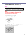
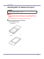
Attaching Paper Feed Unit Type 610
When installing multiple options, install the paper feed unit first.
• The printer weighs about 20 kg (44.1 lb.). When lifting the machine, use the
inset grips on both sides. Otherwise the printer could break or cause injury
if dropped.
❒ Do not slide more than one paper tray out at the same time. Having more than
one full paper tray fully extended could cause the machine to topple.
❒ More than two paper feed units cannot be attached.
❒ Check the printer nameplate to confirm the model code.
A Check the package contains the following:
❖ Paper Feed Unit (including a paper tray)
B Turn off the power of the printer, and then unplug the printer's power cable and the interface cable.
C Remove the adhesive tape from the paper feed unit.
38
Installing Options
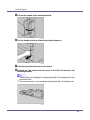
❒ If you attach two paper feed units at the same time, stack them up in advance.
D There are three pins on the top of the paper feed unit that point straight
up. On the bottom of the printer there are three holes. Align the holes
over the pins, and then lower the printer gently onto the paper feed unit.
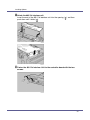
E Attach the interface cable to the printer.
F Plug the printer's power cable back into the wall outlet, and then turn on
the power.
❒ After finishing installation, you can check whether the paper feed unit is
properly installed: Print the configuration page from the “List/Test Print”
menu. If it is installed properly, you will see “Paper Feed Unit (Tray 2)” or
“Paper Feed Unit (Tray 2), Paper Feed Unit (Tray 3)” under the “Options”
list.
❒ If the paper feed unit is not installed properly, repeat the procedure from
the start. If you cannot install it properly even after reinstallation, contact
your sales or service representative.
For printing the configuration page, see p.32 “Test Printing”.
39
Installing Options
See “Loading Paper”, Maintenance Guide.
When adjusting the printing position, see “Adjusting Tray Registration”,
Maintenance Guide.
40
Installing Options
Attaching Envelope Feeder Type 610
❒ This unit is a tray that slides into the optional paper feed unit. Without the optional paper feed unit, this envelope feeder cannot be used.
❒ Your printer can accommodate two optional paper feed units. The envelope
Feeder unit can be used in “Tray 2”. Neither the main unit's feed tray (Tray 1)
nor Tray 3 can be used for this purpose.
❒ Do not slide more than one paper tray out at the same time. Having more than
one full paper tray fully extended could cause the machine to topple.
The following explanation uses the example of installing the envelope feeder unit
in “Tray 2”.
A Check the package contains the following:
❖ Envelope Feeder
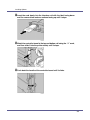
B Pull out the second paper tray (Tray 2) of the optional paper feed unit until it stops. After that, lift it slightly, and then pull it out.
41
Installing Options
❒ The envelope feeder must be used in the top-most optional paper feed unit
(Tray 2).
❒ The tray of the top-most optional paper feed unit is beneath the paper tray.
❒ Keep the paper tray with paper in a cool dark place.
C Lift the front of the envelope feeder, and slide it carefully into the printer
until it stops.
For information about loading paper, see “Loading Envelopes”, Maintenance Guide.
42
Installing Options
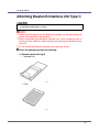
Attaching Memory Unit Type C 256MB
(SDRAM Module)
• Do not touch the inside of the controller board compartment. Doing so may
cause a malfunction or a burn.
❒ Before touching the memory unit, touch something metal to discharge any
static electricity. Static electricity can damage the memory unit.
❒ Do not subject the memory unit to physical shocks.
❒ If a printer hard disk is already installed, temporarily remove it and insert the
memory unit. Reinstall the printer hard disk after inserting the memory unit.
❒ Before using the new memory unit, you must make settings in the printer driver.
A Turn off the power of the printer, and then unplug the printer's power cable and the interface cable.
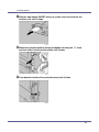
B If the duplex unit is attached, push down the lever on right side (
) and
pull out the duplex unit until it stops ( ).
If the duplex unit is not attached, go to the following steps.
C Remove the two screws holding the controller board in place.
❒ Use a coin or similar object if the screws do not turn easily.
43
Installing Options
❒ The removed screws are required in fastening the controller board.
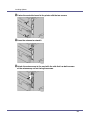
D Pull out the handle of the controller board.
E Pull the handle, and then slide the controller board out.
F Place the controller board on a flat surface.
44
Installing Options
G The memory unit is installed in the slot shown in the illustration below.
H Remove the default memory unit before installing a new memory unit.
Press down the levers on both sides to remove the default memory unit.
I Align the notch of the memory unit to the slot, and then push it down until it clicks.
45
Installing Options
J Match the controller board to the top and bottom rail using the “T” mark,
and then slide it into the printer slowly until it stops.
K Push the handle of the controller board until it clicks.
L Fasten the controller board to the printer with the two screws.
46
Installing Options
M Align the power cable to the left side groove of the duplex unit, and then
slide the duplex unit in until it is connected to the printer.
If the duplex unit is not attached, this step is not necessary.
❒ Be sure to return the provided screwdriver to its original position on the inside of the front cover.
❒ After finishing the installation, you can check the memory unit is properly
installed: Print the configuration page from the “List/Test Print” menu. If it
is installed properly, you will see the memory capacity for “Total Memory”.
❒ To expand memory, remove the default SDRAM module, and then install
the SDRAM module (256 MB). “Total Memory” will be the size of SDRAM
module memory unit you installed.
❒ If the memory unit is not properly installed, repeat the procedure from the
start. If you cannot install it properly even after reinstallation, contact your
sales or service representative.
For printing the configuration page, see p.32 “Test Printing”.
47
Installing Options
Attaching 1394 Interface Unit Type 4510
• Do not touch the inside of the controller board compartment. Doing so may
cause a malfunction or a burn.
❒ The 1394 interface unit uses “IP over 1394” and “SCSI print”. Operating system-compatible connection methods are as follows (IEEE 1394 cannot be
used with Windows 95/98 and Windows NT 4.0):
• Windows Me
“IP over 1394”
• Windows 2000
“SCSI print”
• Windows XP, Windows Server 2003
“IP over 1394”, “SCSI print”
❒ Under Windows 2000, the 1394 interface unit can only be used with Service
Pack 1 or later. The client cannot install the printer driver without using an account that has administrators access rights.
❒ Before touching the 1394 interface unit, ground yourself by touching something metal to discharge any static electricity. Static electricity can damage the
1394 interface unit.
❒ Do not plug or unplug the 1394 interface cable while installing the printer driver.
❒ Use the 1394 interface cable that comes with 1394 interface unit.
A Check the package contains the following:
❖ 1394 Interface Unit Type 4510
48
Installing Options
❖ 1394 Interface Cable (6 pins x 4 pins)
❖ 1394 Interface Cable (6 pins x 6 pins)
B Turn off the power of the printer, and then unplug the printer's power cable and the interface cable.
C If the duplex unit is attached, push down the lever on right side (
) and
pull out the duplex Unit until it stops ( ).
If the duplex unit is not attached, go to the following steps.
D Remove the two screws holding the controller board in place.
❒ Use a coin or similar object if the screws do not turn easily.
49
Installing Options
❒ These screws are used again in fastening the controller board.
E Pull out the handle of the controller board.
F Pull the handle, and then slide the controller board out.
G Place the controller board on a flat surface.
H Remove the two screws and the cover of the 1394 interface unit mounting bracket.
❒ These screws are used again in fastening the 1394 interface unit to the
controller board.
50
Installing Options
❒ The removed cover is not used when installing the 1394 interface unit.
I Attach the 1394 interface unit to the controller board.
Insert the end of the 1394 interface unit into the opening ( ), and then push
down until it clicks ( ).
51
Installing Options
J Fasten the 1394 interface unit to the controller board.
K Match the controller board to the top and bottom rail using the “T” mark,
and then slide it into the printer slowly until it stops.
L Push back the handle of the controller board until it clicks.
52
Installing Options
M Fasten the controller board to the printer with the two screws.
N Align the power cable to the left side groove of the duplex unit, and then
slide the duplex unit in until it is connected to the printer.
If the duplex unit is not attached, this step is not necessary.
❒ After finishing installation, you can check the 1394 interface unit is properly
installed: Print the configuration page from the “List/Test Print” menu. If it
is installed properly, you will see “IEEE1394” for “Controller Option”.
❒ You need to make settings with the control panel before using the 1394 interface unit. For more information, see p.91 “IEEE 1394 Configuration”.
❒ If the 1394 interface unit is not installed properly, repeat the procedure from
the start. If you cannot install it properly even after reinstallation, contact
your sales or service representative.
For printing the configuration page, see p.32 “Test Printing”.
53
Installing Options
Attaching 802.11b Interface Unit Type F
• Do not touch the inside of the controller board compartment. Doing so may
cause a machine malfunction or a burn.
❒ Before touching the 802.11b interface unit, touch something metal to discharge any static electricity. Static electricity can damage the 802.11b interface unit.
❒ Do not subject the 802.11b interface unit to physical shocks.
A Check the package contains the following:
❖ 802.11b Interface Unit Type F
• Interface Unit
• Card
54
Installing Options
• Antenna Cap
B Turn off the power of the printer, and then unplug the printer's power cable and the interface cable.
C If the duplex unit is attached, push down the lever on right side (
) and
pull out the duplex unit until it stops ( ).
If the duplex unit is not attached, go to the following steps.
D Remove the two screws holding the controller board in place.
❒ Use a coin or similar object if the screws do not turn easily.
❒ These screws are used again in fastening the controller board.
55
Installing Options
E Pull out the handle of the controller board.
F Pull the handle, and then slide the controller board out.
G Place the controller board on a flat surface.
H Remove the two screws and the cover of
the 802.11b interface unit
mounting bracket.
❒ These screws are used again in fastening the 802.11b interface unit to the
controller board.
❒ The removed cover is not used when installing the 802.11b interface unit.
56
Installing Options
I Attach the 802.11b interface unit.
Insert the end of the 802.11b interface unit into the opening ( ), and then
push down until it clicks ( ).
J Fasten the 802.11b Interface Unit to the controller board with the two
screws.
57
Installing Options
K Insert the card slowly into the interface unit with the label facing down
and the uneven black antenna surface facing up until it stops.
L Match the controller board to the top and bottom rail using the “T” mark,
and then slide it into the printer slowly until it stops.
M Push back the handle of the controller board until it clicks.
58
Installing Options
N Fasten the controller board to the printer with the two screws.
O Attach the antenna cap to the card with the side that has both corners
of the antenna cap cut out facing the screws.
P Align the power cable to the left side groove of the duplex unit, and then
slide the duplex unit in until it is connected to the printer.
If the duplex unit is not attached, this step is not necessary.
❒ After finishing installation, you can check the 802.11b interface unit is properly installed: Print the configuration page from the “List/Test Print” menu.
If it is installed properly, you will see “IEEE 802.11b” for “Controller Option”.
59
Installing Options
❒ If the 802.11b interface unit is not installed properly, repeat the procedure
from the start. If you cannot install it properly even after reinstallation, contact your sales or service representative.
❒ You need to make settings with the control panel before using the 802.11b
interface unit. For more information, see p.85 “IEEE 802.11b (Wireless
LAN) Configuration”.
For printing the configuration page, see p.32 “Test Printing”.
60
Installing Options
Attaching Bluetooth Interface Unit Type C
• Do not touch inside the controller board compartment. Doing so may cause
a machine malfunction or a burn.
❒ When using the printer with the Bluetooth interface unit installed, Bluetooth
needs to be installed on the computer.
❒ Before manipulating the Bluetooth interface unit, touch something metal to
discharge static electricity. Static electricity can damage the Bluetooth interface unit.
❒ Do not subject the Bluetooth interface unit to physical shocks.
A Check the package contains the following:
❖ Bluetooth Interface Unit Type C
• Interface Unit
• Card
61
Installing Options
• Antenna Cap
B Turn off the power of the printer, and then unplug the printer's power cable and the interface cable.
C If the duplex unit is attached, push down the lever on right side (
) and
then pull out the duplex unit until it stops ( ).
If the duplex unit is not attached, go to the following steps.
D Remove the two screws holding the controller board in place.
❒ Use a coin or similar object if the screws do not turn easily.
❒ These screws are used again in fastening the controller board.
62
Installing Options
E Pull out the handle of the controller board.
F Pull the handle, and then slide the controller board out.
G Place the controller board on a flat surface.
H Remove the two screws and the cover of the Bluetooth interface unit
mounting bracket.
❒ These screws are used again in fastening the Bluetooth interface unit to
the controller board.
❒ The removed cover is not used when installing the Bluetooth interface unit.
63
Installing Options
I Attach the Bluetooth interface unit.
Insert the end of the Bluetooth interface unit to the opening ( ), and then push
down until it clicks ( ).
J Fasten the network interface unit to the controller board with the two
screws.
64
Installing Options
K With the side labeled INSERT facing up, slowly insert the card into the
interface unit, until it stops.
L Match the controller board to the top and bottom rail using the “T” mark,
and then slide it into the printer slowly until it stops.
M Push back the handle of the controller board until it clicks.
65
Installing Options
N Fasten the controller board to the printer with the two screws.
O Press the antenna to extend it.
P Attach the antenna cap to the card with the side that has both corners
of the antenna cap cut out facing the screws.
66
Installing Options
Q Align the power cable to the left side groove of the duplex unit, and then
slide the duplex unit in until it is connected to the printer.
If the duplex unit is not attached, this step is not necessary.
❒ After finishing installation, you can check the Bluetooth interface unit is
properly installed: Print the configuration page from the “List/Test Print”
menu. If it is installed properly, you will see “Bluetooth” for “Controller Option”.
❒ If the Bluetooth interface unit is not installed properly, repeat the procedure
from the start. If you cannot install it properly even after reinstallation, contact your sales or service representative.
For printing the configuration page, see p.32 “Test Printing”.
67
Installing Options
Attaching Hard Disk Drive Type 2600
❒ Before touching the hard disk drive, touch something metal to discharge any
static electricity. Static electricity can damage the hard disk drive.
A Check the package contains the following:
❖ Hard Disk Drive Type 2600
B Turn off the power of the printer, and then unplug the power cable.
C Remove the two screws and the cover of the hard disk drive mounting
bracket.
❒ Use a coin or similar object if the screws do not turn easily.
❒ The screws and cover are not used when installing the hard disk drive.
68
Installing Options
D Slowly insert the hard disk drive while aligning it with the top and bottom rails in the printer until it stops.
E Fasten the two screws (using a coin, etc.) to fix the hard disk drive.
❒ After finishing installation, you can check whether the hard disk drive is
properly installed: Print the configuration page from the “List/Test Print”
menu. If it is installed properly, you will see “Printer Hard Disk Drive” for
“Controller Option”.
❒ If the hard disk drive is not installed properly, repeat the procedure from the
start. If you cannot install it properly even after reinstallation, contact your
sales or service representative.
For printing the configuration page, see p.32 “Test Printing”.
69
Installing Options
Attaching Network Data Protection Unit
Type B
❒ Protect the network data protection unit from physical shocks.
❒ Use the under slot for the data protection unit.
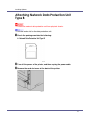
A Check the package contains the following:
❖ Network Data Protection Unit Type B
B Turn off the power of the printer, and then unplug the power cable.
C Remove the card slot cover at the back of the printer.
70
Installing Options
D Carefully insert the network data protection unit, until the card clicks
into the place.
E Reattach the cover over the network data protection unit. Fasten the
screw to secure the cover.
❒ Do not touch the network data protection unit while the machine is in use.
It may come loose, even if pushed only slightly.
71
Installing Options
Attaching Duplex Unit AD610
❒ If you attach the duplex unit and the paper feed unit, the paper feed unit must
be attached prior to attaching the duplex unit.
❒ Check the printer nameplate to confirm the model code.
A Check the package contains the following:
❖ Duplex Unit
B Turn off the power of the printer, and then unplug the power cable.
C Remove the adhesive tapes.
72
Installing Options
D Open the rear cover by pushing the two knobs as shown in the illustration.
E Remove the rear cover in the horizontal direction.
❒ The rear cover of the printer is not used when attaching the duplex unit.
❒ Store the removed rear cover for possible future use.
73
Installing Options
F Align the power cable to the left side groove of the duplex unit, and then
slide the duplex unit in until it is connected to the printer.
❒ After finishing installation, you can check the duplex unit is properly installed: Print the configuration page from the “List/Test Print” menu. If the
new device is listed in the column of configuration options, then it has been
properly installed.
❒ If the duplex unit is not installed properly, repeat the procedure from the
start. If you cannot install it properly even after reinstallation, contact your
sales or service representative.
❒ If the printing position is not correct, adjust the registration of the trays. For
more information about adjusting the registration of the trays, see “Adjusting Tray Registration”, Maintenance Guide.
For printing the configuration page, see p.32 “Test Printing”.
74
Connecting the Printer
Network Connection
Follow the procedure below to connect the printer to the computer through the
network. Prepare the hub and other network devices before connecting the 10
BASE-T or 100 BASE-TX cable to the machine's Ethernet port.
❒ Use shielded Ethernet cable. Unshielded cables create electromagnetic interference that could cause malfunctions.
❒ Ethernet cable is not supplied with this machine. Select your cable according
to the network environment.
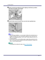
A Connect the Ethernet cable to the Ethernet port.
B Connect the other end of the cable to the printer's network, such as a
hub.
For details about network environment settings, see Software Guide.
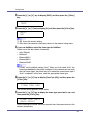
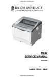
- Reading
the LED Lamps
G1168605A_1.10
Copyright © 2004, 2005
75
Connecting the Printer
1. Green: lit when the printer is properly connected to the network.
2. Yellow: lit when 100BASE-TX is being used. Unlit when 10BASE-T is being used.
76
Connecting the Printer
USB Connection
❒ USB2.0 interface cable is not supplied. Obtain it separately, according to the
computer you are using.
❒ USB connection is possible under Windows 98 SE/Me/2000/XP, Windows
Server 2003, Mac OS 9.x, and Mac OS X v10.3 or higher.
❒ Windows 98SE/Me supports USB1.1 speeds.
❒ USB connection with Macintosh is only possible via the printer's USB port.
A Connect the square-shaped connector of the USB2.0 cable to the USB
port.
B Connect the opposite end's flat connector to devices such as your computer's USB interface, or a USB hub.
For details about settings for USB connection printing, see Software Guide.
77
Connecting the Printer
Parallel Connection
❒ The parallel interface cable is not provided with the printer.
❒ The printer's parallel connection is a standard bidirectional interface that requires an IEEE 1284-compliant 36-pin parallel cable and host computer parallel port.
❒ Use shielded interface cable. Unshielded cables create electromagnetic interference that could cause malfunctions.
A Turn off the printer and computer.
B Connect the cable to the interface connector.
C Securely attach the other end of the parallel cable to your computer's
parallel port. Secure the cable.
For details about settings for parallel connection printing, see Software
Guide.
78
Connecting the Printer
IEEE 1394 Connection
❒ Use the 1394 interface cable provided with the 1394 interface unit.
❒ You cannot plug devices together to create loops.
❒ Do not use a cable more than 4.5 meters (14.8 feet) long.
A Connect the interface cable to the 1394 interface unit.
B Connect the other end to the host computer.
❒ You can use either connector.
❒ Either of the two connectors for the 1394 interface unit can be used.
❒ If you have an interface cable with a ferrite core, connect the ferrite core
end to the printer.
For details about settings for parallel connection printing, see Software
Guide.
79
Configuration
Ethernet Configuration
Make the following network settings according to the network interface you are
using.
You can use SmartDeviceMonitor for Admin or a Web browser to make IP address-related settings in a TCP/IP-capable environment.
❒ Configure the printer for the network using the control panel.
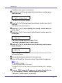
❒ The following table shows the control panel settings and their default values.
These items appear in the [Host Interface] menu.
Setting Name
Value
DHCP
On
IP Address
011.022.033.044
Subnet Mask
000.000.000.000
Gateway Address
000.000.000.000
Frame Type (NW)
Auto
Active Protocol
TCP/IP
Active
NetWare
Active
SMB
Active
AppleTalk
Active
Ethernet Speed
Auto Select
LAN Type
Ethernet
❒ If DHCP is in use, “IP Address”, “Subnet Mask”, and “Gateway Address” are
all set automatically.
❒ Make this setting only when it is necessary. See Software Guide.
A Press the {Menu} key.
G1168605A_1.10
Copyright © 2004, 2005
80
Configuration
The [Menu] screen appears on the display.
B Press the {U} or {T} key to display [Host Interface] menu, and then press
the {# Enter} key.
Menu:
Host Interface
The interface setting menu appears.
C Press the {U} or {T} key to display [Network Setup], and then press the {#
Enter} key.
The network setup menu appears.
D Press the {U} or {T} key to display [Active Protocol], and then press the
{# Enter} key.
E Press the {U} or {T} key to select Active Protocol, and then press the
{# Enter} key.
Active Protocol:
TCP/IP
The following example explains activating TCP/IP.
The [Active] or [Not Active] selection screen appears.
F Press the {U} or {T} key to select [Active] or [Not Active], and then press
the {# Enter} key.
TCP/IP:
*Active
After the settings are made, about two seconds later, the screen returns to the
active protocol menu.
G Set other protocols you need to set in the same way.
H Press the {Escape} key, the screen returns to the network setup menu.
❒ The default is “Active”.
❒ Leave unused protocols “Not Active”.
❒ Enable TCP/IP to use the Pure IP environment of NetWare 5/5.1, NetWare
6/6.5.
I If you use TCP/IP, assign the IP address to the printer. Press the {U} or
{T} key to display [IP Address], and then press the {# Enter} key.
The current IP address appears on the display.
81
Configuration
To get the IP address for the printer, contact your network administrator.
J Press the {U} or {T} key to enter the left most entry field of the IP address, and then press the {# Enter} key.
IP Address:
192.022.033.044
Press the {# Enter} key, the screen changes, and the next field can then be
entered.
❒
❒
❒
❒
❒
Do not set “011.022.033.044” as the IP address.
The value moves by 10 if the {U} or {T} key is kept pressed.
When the {# Enter} key is pressed, the cursor moves to the next field.
To display the previous field, press the {Escape} key.
Press the {Escape} key when no value is entered and the screen will return
to the network setup menu, without the IP address changing.
K Make the other settings in the same way, and then press the {# Enter}
key.
IP Address:
192.168.000.010
After the settings are made, about two seconds later, the screen returns to the
network setup menu.
L If you use TCP/IP, assign [Subnet Mask] and [Gateway Address] following the
same procedure for entering the IP address.
M When you use this machine in DHCP environment, set DHCP to “On”.
❒ When DHCP is “On”, you cannot make settings for the following items:
• IP Address
• Subnet Mask
• Gateway Address
❒ Consult your network administrator for information about making network
settings.
82
Configuration
N Press the {U} or {T} key to display [DHCP], and then press the {# Enter}
key.
Network Setup:
DHCP
O Press the {U} or {T} key to display [On], and then press the {# Enter} key.
DHCP:
*On
❒ “p” shows the current setting.
❒ After about two seconds, the display returns to the network setup menu.
P If you use NetWare, select the frame type for NetWare.
Select one of the items below if necessary.
• Auto (Default)
• Ethernet ll
• Ethernet 802.2
• Ethernet 802.3
• Ethernet SNAP
❒ Usually, use the default setting (“Auto”). When you first select “Auto”, the
frame type detected by the printer is adopted. If your network can use more
than two frame types, the printer may fail to select the correct frame type if
“Auto” is selected. In this case, select the appropriate frame type.
Q Press the {U} or {T} key to display [Frame Type (NW)], and then press the
{# Enter} key.
Network Setup:
Frame Type (NW)
The current setting appears on the display.
R Press the {U} or {T} key to display the frame type you want to use, and
then press the {# Enter} key.
Frame Type (NW):
*Auto Select
After the settings are made, about two seconds later, the screen returns to the
network setup menu.
83
Configuration
S Press the {Online} key.
The initial screen appears.
Ready
T Print a configuration page to confirm the settings made.
For details about printing the configuration page, see p.32 “Test Printing”.
84
Configuration
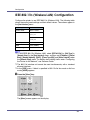
IEEE 802.11b (Wireless LAN) Configuration
Configure the printer to use IEEE 802.11b (Wireless LAN). The following table
shows the control panel settings and their default values. These items appear in
the [Host Interface] menu.
Setting Name
Default Value
Comm. Mode
802.11 Ad hoc
Channel
Inch version
(1-11) 11
Metric version
(1-13) 13
Trans. Speed
Auto
SSID
blank (ASSID)
WEP Setting
Not Active
❒ To use IEEE 802.11b (Wireless LAN), select [IEEE 802.11b] for [LAN Type] in
[Network Setup] in the [Host Interface] menu, and then set [IP Address], [Subnet
Mask], [Gateway Address], [DHCP], [Frame Type (NW)] and [Active Protocol] under
the [Network Setup] menu. For details about setting items under “Configuring
the Printer for the Network”, see Software Guide.
❒ The 802.11b interface unit cannot be used simultaneously with a standard
ethernet interface.
❒ In the [SSID] menu, if blank is specified in 802.11b Ad hoc mode or Ad hoc
mode, [ASSID] appears.
A Press the {Menu} key.
The [Menu] screen appears on the display.
85
Configuration
B Press the {U} or {T} key to display [Host Interface], and then press the {#
Enter} key.
Menu:
Host Interface
The interface setting menu appears.
C Press the {U} or {T} key to display [IEEE 802.11b] , and then press the {#
Enter} key.
The IEEE 802.11b setting menu appears.
D Press the {U} or {T} key to display [Comm. Mode], and then press the {#
Enter} key.
E Press
the {U} or {T} key to select the transmission mode of IEEE
802.11b, and then press the {# Enter} key.
Comm. Mode:
*802.11 Ad hoc
After the settings are made, about two seconds later, the screen returns to the
IEEE 802.11b setting menu.
❒ The factory default is [802.11 Ad hoc].
❒ To use an IEEE 802.11b card for which the SSID (Network Name) setting
is not necessary, select [Ad hoc].
❒ The transmission mode of IEEE 802.11b can also be set using a Web
browser. For details, see Web Image Monitor Help, and “Using Web Image
Monitor”, Software Guide.
F If [802.11 Ad hoc] or [Ad hoc] is selected for [Comm. Mode], set the channel to
use for transmission.
❒ Confirm the network administrator for the channel to use.
G Press the {U} or {T} key to display [Channel], and then press the {# Enter}
key.
The channel currently used appears on the display.
H Press the {U} or {T} key to enter the channel, and then press the {# Enter} key.
Channel:
(1-11)
11
86
Configuration
I Set [Trans. Speed] in the same way.
❒ The factory default is [Auto]. If you need to change the transmitting speed
depending on environment you are using, select the appropriate transmitting speed.
J If [Infrastructure] or [802.11 Ad hoc] is selected for [Comm. Mode], set SSID to
use for transmission.
❒ Confirm the network administrator for SSID to use.
❒ SSID can also be set using a Web browser. For details, see the Web Image
Monitor Help, and “Using Web Image Monitor”, Software Guide.
K Press the {U} or {T} key to display [SSID], and then press the {# Enter}
key.
The following message appears on the display.
SSID:
View
If an SSID has been set, you can check the set SSID. Press the {# Enter} key.
L Press the {U} or {T} key to display [Enter ID], and then press the {# Enter}
key.
The following message appears on the display.
SSID:
k
[ 0]
The value in brackets at the upper right is the number of characters entered.
M Press the {U} or {T} key to select characters, and then press the {# Enter} key.
SSID:
Ak
[ 1]
You can now enter the next character.
N Continue entering the key.
❒ The characters that can be used are ASCII 0x20-0x7e (32 bytes).
❒ To display the previous character, press the {Escape} key.
87
Configuration
O After entering the key, press the {# Enter} key twice.
SSID:
[32]
AAAAAAAAAAAAAAAA
After the settings are made, about two seconds later, the screen returns to the
IEEE 802.11b setting menu.
P In the case of using a WEP key on a network, activate the WEP setting
to be used for communication along with WEP.
❒ Confirm the network administrator for the WEP Key to use.
❒ WEP key can also be set using a Web browser. For details, see Web Image Monitor Help.
Q Press the {U} or {T} key to display [WEP Setting], and then press the {#
Enter} key.
The following message appears on the display.
WEP Setting:
*Not Active
R Press the {U} or {T} key to display [Active], and then press the {# Enter}
key.
The following message appears on the display.
Change WEP Key:
Yes (HEX)
❒ When setting the WEP Setting to [Active], you will need to enter the WEP
key. If you have not entered the key, be sure to enter it.
❒ If you have entered the WEP key and change the setting, press the {U} or
{T} key to display [No], and then press the {# Enter} key.
S Press the {U} or {T} key to display [Yes (HEX)] when inputting a hexadecimal WEP key or [Yes (ASCII)] when inputting an ASCII WEP key. Then
press the {# Enter} key.
WEP Key:
k
[ 0]
The value in brackets at the upper right is the number of characters entered.
88
Configuration
T Press the {U} or {T} key to select characters, and then press the {# Enter} key.
WEP Key:
*k
[ 1]
You can now enter the next character.
WEP Key:
**k
[ 2]
Continue entering the key.
❒ When using 64 bit WEP, up to 10 characters can be used for hexadecimal
and up to five characters for ASCII. When using 128 bit WEP, up to 26
characters can be used for hexadecimal and up to 13 characters for ASCII.
❒ The number of characters that can be entered is limited to 10 or 26 for
hexadecimal and 5 or 13 for ASCII. If you try to enter too many characters,
the following message appears:
• hexadecimal
Error: Enter 10
or 26 characters
• ASCII
Error: Enter 5
or 13 characters
❒ For ASCII character strings, each capital letter and lowercase letter is recognized respectively.
❒ To display the previous character, press the {Escape} key.
U After entering the key, press the {# Enter} key.
WEP Key:
[26]
***************A
After the settings are made, about two seconds later, the screen returns to the
IEEE 802.11b setting menu.
V Press the {Online} key.
89
Configuration
The initial screen appears.
Ready
W Print a configuration page to confirm the settings made.
For details about printing the configuration page, see p.32 “Test Printing”.
90
Configuration
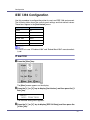
IEEE 1394 Configuration
Use this procedure to configure the printer for use in an IEEE 1394 environment.
The following table shows the control panel settings and their default values.
These items appear in the [Host Interface] menu.
Setting Name
Value
DHCP
On
IP Address1394
011.022.033.044
Subnet Mask1394
000.000.000.000
IP over 1394
Active
SCSI print
Active
Bidi-SCSI print
On
❒ If DHCP is in use, “IP Address1394” and “Subnet Mask1394” are automatically set.
IP over 1394
A Press the {Menu} key.
The [Menu] screen appears on the display.
B Press the {U} or {T} key to display [Host Interface], and then press the {#
Enter} key.
Menu:
Host Interface
The interface setting menu appears.
C Press the {U} or {T} key to display [IEEE 1394 Setup], and then press the
{# Enter} key.
91
Configuration
The IEEE 1394 setting menu appears.
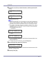
D Press the {U} or {T} key to display [IP over 1394], and then press the {#
Enter} key.
The IP over 1394 setting menu appears.
E Press the {U} or {T} key to select either [Active] or [Not Active], and then
press the {# Enter} key.
IP over 1394:
*Active
After the settings are made, about two seconds later, the screen returns to the
IEEE 1394 setting menu.
F Assign the IP address to the printer. Press the {U} or {T} key to display
[IP Address1394], and then press the {# Enter} key.
The current IP address appears on the display.
❒ Do not set the same IP address as that used for the ethernet network settings or in the same subnet. Also, do not specify the same subnet mask.
❒ Do not set “011.022.033.044” as the IP address.
❒ To get the IP address for the printer, contact your network administrator.
G Press the {U} or {T} key to enter the left most entry field of the IP address, and then press the {# Enter} key.
IP Address1394:
19k.022.033.044
The pointer (k) moves to the next entry field automatically.
IP Address1394:
192.02k.033.044
❒ The value moves by 10 if the {U} or {T} key is kept pressed.
❒ You can return the pointer (k) to the previous (left) entry field by pressing
the {Escape} key.
❒ If you press the {Escape} key when the pointer (k) is on the leftmost position, the selected IP address is reset.
H Set other fields similarly, and then press the {# Enter} key.
The settings are made and after about two seconds, the screen returns to the
IEEE 1394 setting menu.
92
Configuration
I Set [Subnet Mask1394] in the same way.
J Press the {Online} key.
The initial screen appears.
Ready
K Print a configuration page to confirm the settings made.
For printing the configuration page, see “Printing a Configuration Page”,
Software Guide.
SCSI print
A Press the {Menu} key.
The [Menu] screen appears on the display.
B Press the {U} or {T} key to display [Host Interface], and then press the {#
Enter} key.
Menu:
Host Interface
The interface setting menu appears.
C Press the {U} or {T} key to display [IEEE 1394 Setup], and then press the
{# Enter} key.
The IEEE 1394 setting menu appears.
D Set [SCSI print] and [Bidi-SCSI print] if necessary.
❒ The default setting is “Active”.
93
Configuration
E Press the {U} or {T} key to display [SCSI print], and the press the {# Enter}
key.
F Press the {U} or {T} key to select either [Active] or [Not Active], and then
press the {# Enter} key.
SCSI print:
*Active
After the settings are made, about two seconds later, the screen returns to the
IEEE 1394 setting menu.
G Set [Bidi-SCSI print] in the same way.
H Press the {Online} key.
The initial screen appears.
Ready
I Print a configuration page to confirm the settings made.
For details about printing the configuration page, see p.32 “Test Printing”.
94
Installing the Printer Driver
Quick Install
Windows 95/98/Me/2000/XP, Windows Server 2003, and Windows NT 4.0 users
can easily install this software using the CD-ROM provided.
Using Quick Install, the PCL printer driver and RPCS printer driver and SmartDeviceMonitor for Client is installed under network environment, and TCP/IP
port will be set.
❒ To install printer driver under Windows 2000/XP Professional, Windows Server 2003, and Windows NT 4.0, you must have an account that has Manage
Printers permission. Log on as an Administrator.
❒ Only the printer driver, and not the SmartDeviceMonitor for Client, is installed
when using this printer under USB, parallel, or 1394 connection. If you connect using USB, see Software Guide.
A Quit all applications currently running.
B Insert the CD-ROM into the CD-ROM drive.
The installer starts.
Auto Run may not work with certain operating system settings. If this happens, launch “Setup.exe” on the CD-ROM root directory.
C Select an interface language, and then click [OK].
The default interface language is English.
D Click [Quick Install].
The software license agreement appears in the [License Agreement] dialog box.
G1168605A_1.10
Copyright © 2004, 2005
95
Installing the Printer Driver
E After reading the agreement, click [I accept the agreement], and then click
[Next].
F Select the printer model you want to use in the [Select Printer] dialog box.
❒ For network connection via TCP/IP, select the printer whose IP address is
displayed in [Connect To].
❒ For parallel connection, select the printer whose printer port is displayed in
[Connect To].
G Click [Install].
The printer driver installation starts.
H Click [Finish].
A message about restarting the computer may appear. Restart the computer
to complete installation.
I Click [Exit] in the first dialog box of the installer, and then take out the
CD-ROM.
❒ To stop installation of the selected software, click [Cancel] before installation is complete. Restart the computer, and then reinstall the other software
or printer drivers.
❒ Auto Run may not work with certain operating system settings. If this happens, launch “Setup.exe” on the CD-ROM root directory.
❒ Select a printer to whose IP address is displayed in [Connect To] to install
SmartDeviceMonitor for Client when using TCP/IP.
Quick Install is not available unless bidirectional communication between
the printer and computer is enabled via parallel connection. See “Install
SmartDeviceMonitor for Client from the CD-ROM provided.”, Software
Guide, for details about bidirectional communication between printer and
computer.
96
Installing the Printer Driver
Install the Operating Instructions
The CD-ROM provided with the printer contains an HTML Operating Instructions
Manual in HTML version. Follow the above instructions to install it.
❒ System Requirements :
• Windows 95/98/Me, Windows 2000/XP, Windows Server 2003 or Windows
NT4.0.
• 800 x 600 or higher monitor resolution.
❒ Web Browsers :
• Microsoft Internet Explorer 4.01 SP2 or later.
• Netscape 6.2 or later.
❒ If you are using Internet Explorer 3.02 or earlier, or Netscape Navigator 4.05
or earlier as your Web browser, a simpler version of the Operating Instructions
Manual is displayed.
A Quit all applications currently running.
B Insert the CD-ROM into the CD-ROM drive.
The installer starts.
Auto Run may not work under certain operating system setting. If this is the
case, launch “Setup.exe” on the CD-ROM root directory.
C Select an interface language, and then click [OK].
D Click [Install manuals].
E Follow the instructions on the screen to complete the installation.
F Click [Finish] when the installation is completed.
G Click [Exit].
❒ Auto Run may not work under certain operating system setting. If this is the
case, copy all datas on the CD-ROM root directory to your hard disk drive,
and then launch “Setup.exe” to start the installation.
❒ To uninstall the Operating Instructions Manual, select [Programs] in the
[Start] menu, select your printer driver, and then click [Uninstall]. You can
uninstall each Manual Guide separately.
❒ If you are using an incompatible Web browser and the simpler version of
the Operating Instructions Manual does not correctly display correctly,
open folder “MANUAL\R_MANUAL\ US_ENG\ (SETUP or MAINTE or
SOFTWARE) \unv\” on the CD-ROM. Double-click on “index.htm”.
97