1
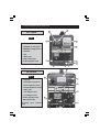
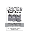
HEAVY DUTY BATTERY
BOOSTERS / CHARGERS
MODEL Nos. BC185N & BC200N
OPERATING INSTRUCTIONS
©
1106
Thank you for purchasing this CLARKE Battery Charger. These units are suitable for
charging and boosting 12 Volt lead acid batteries. Model BC200N is also capable
of charging 24 Volt batteries.
Before attempting to operate the unit, please read this instruction manual
thoroughly, and follow all directions carefully. By doing so you will ensure the safety
of yourself, and others around you, and at the same time, you should look forward
to the unit giving long and trouble free service.
GUARANTEE
This product is guaranteed against faults in manufacture for 12 months from date
of purchase. Please keep your receipt as proof of purchase.
This guarantee is invalid if the product has been found to have been abused in
any way, or not used for the purpose for which it was intended, or to have been
tampered with in any way. The reason for return must be clearly stated.
This guarantee does not affect your statutory rights.
CONTENTS
PAGE
Parts and Service Contacts ............................................................ 2
Safety Precautions ........................................................................... 4
Electrical Connections .. BC185N .................................................. 5
......................................... BC200N .................................................. 5
Parts Identification ........................................................................... 6
Assembly Instructions ...................................................................... 7
Procedure For Normal Charging ................................................... 8
Procedure For Engine Starting ....................................................... 10
Parts List and Diagram .. BC185N .................................................. 11
Parts List and Diagram .. BC200N .................................................. 12
Wiring Diagrams ............................................................................... 13
Specifications ................................................................................... 15
Replacement Fuses ......................................................................... 15
Parts & Service Contacts ................................................................ 15
3
IMPORTANT: SAFETY PRECAUTIONS
PLEASE READ BEFORE USING THIS UNIT
1.
WARNING: Some electronic equipment can be damaged by boost
charging or use of start facility. Check your vehicle handbook before using
your Start ’N’ Charge. If in doubt consult the vehicle manufacturer.
Nevertheless, you should not operate this equipment unless you are fully
conversant with vehicle electrical systems, and battery charging techniques.
2.
WARNING: Because highly inflammable hydrogen gas is released in the
process of battery charging, please remember to switch OFF the charger
first, and so avoid sparking which will occur when CONNECTING OR
DISCONNECTING LIVE LEADS.
3.
Black negative (-ve) lead must always be clipped to the negative, and Red
positive (+ve) lead must always be clipped to the positive.
When charging with battery installed in vehicle, or boosting, FIRST connect the
appropriate lead to the UNEARTHED battery terminal (on most modern cars this
is the positive (+ve) terminal), then connect the other lead to the chassis (or a
suitable engine bolt) away from the battery and fuel line. It is advisable to
disconnect the unearthed terminal from the battery, when charging in situ.
When disconnecting, remove the chassis lead FIRST, then the battery lead.
4.
To prevent battery overheating and consequent damage, use the BOOST
facility sparingly and do not exceed our recommendations.
5.
Battery acid is highly corrosive. If spillage occurs, wipe off immediately and
wash copiously with water. Particularly avoid contact with the eyes, but if this
occurs, you must seek medical advice.
6.
When charging is completed, ensure that the vehicle battery leads are
secured to the proper terminals which should be clean and lightly smeared
with petroleum jelly to prevent corrosion. Finally, re-check the electrolyte level.
7.
Do not expose this unit to rain.
8.
Never touch together the negative and positive leads on this unit whilst the
unit is switched on.
9.
Never attempt any electrical or mechanical repair. If you have a problem
with your machine contact your local stockist for service information.
10.
WARNING: Certain types of sealed or maintenance-free batteries need
extra care when charging. Please consult battery manufacturers instructions
before using this unit.
11.
WARNING: Since toxic fumes may be released during battery charging,
ONLY USE THIS UNIT IN A WELL VENTILATED AREA.
12. Before charging ensure the battery terminals are clean and that the cells are filled
with electrolyte to the correct level by adding distilled water where necessary.
4
.
ELECTRICAL CONNECTIONS
BC185N
WARNING! THIS APPLIANCE MUST BE EARTHED.
Connect the mains lead to a 230 volt (50Hz) domestic electrical supply via a standard 13
amp BS 1363 plug fitted with a 13 amp fuse, or a suitably fused isolator switch.
IMPORTANT: The wires in the mains lead are coloured in accordance with the following code:
Green & Yellow
Blue
Brown
-
Earth
Neutral
Live
As the colours of the flexible cord of this appliance may not correspond with the coloured
markings identifying terminals in your plug, proceed as follows:
•
•
•
Connect GREEN & YELLOW coloured cord to plug terminal marked with a letter ‘E’ or
Earth symbol “ ”, or coloured GREEN or GREEN & YELLOW.
Connect BROWN coloured cord to plug terminal marked ‘L’ or coloured RED.
Connect BLUE coloured cord to plug terminal marked ‘N’ or coloured BLACK.
We strongly recommend that this unit is connected to the mains supply via a Residual
Current Device (RCD).
IMPORTANT!
If this appliance is fitted with a plug which is moulded onto the electric cable (i.e.
non-rewireable) please note:
1. The plug must be thrown away if it is cut from the electric cable. There is a
danger of electric shock if it is subsequently inserted into a socket outlet.
2. Never use the plug without the fuse cover fitted.
3. Should you wish to replace a detachable fuse carrier, ensure that the correct
replacement is used (as indicated by marking or colour code).
4. Replacement fuse covers can be obtained from your local dealer or most
electrical stockists.
Fuse Rating
The fuse in the plug must be replaced with one of the same rating (13 amps) and this
replacement must be ASTA approved to BS1362.
Extension Cable
If an extension cable is fitted, ensure the minimum cross section of the conductor is 1.5mm2
for up to 15 metres in length, and 2.5mm2 for up to 25 metres.
BC200N
This unit MUST be connected to a 230V 50Hz, single phase supply, through a suitably fused
isolator, with a fuse rating of 15 Amps. DO NOT connect via a 13 Amp Plug.
Leads are connected as described above
5
PARTS IDENTIFICATION
BC185N
FIG. 1
A - ON/OFF Switch
B- Charge/Boost Start Switch
C- MIN/MAX Charge Rate Sw.
D - Ammeter
E - Fuse
F - Mains Lead
G - RED, Positive Lead
H - BLACK Negative Lead
BC200N
FIG. 2
A - Ammeter
B - Amperage Control Knob
C - Function Indicator Lamp
D - Over5load Indicator Lamp
E - Mains Lead
F - 24V charge socket
G - 12V Charge socket
H - BLACK Negative Lead
J - RED Positive Lead
Not Shown - Fuse - on back
panel
6
ASSEMBLY
The BC185N Charger/Booster is fully assembled, whereas the BC200N requires the
wheel, foot and handle to be attached before use, as follows:
1.
From the bag of loose parts, locate the four screws with washers and nuts with
which to secure the foot to the base of the unit. Ensure the washers are at the
screw heads. DO NOT fully tighten the nuts. Note that the foot is located at
the front of the charger, the axle housing towards the rear.
2.
Slide a wheel on to the axle, then thread the axle into position between the
foot and the body of the charger. Slide the second wheel on to the axle and
secure by pushing on the special locking washer, noting that the angled tines
point outwards.
3.
Tighten the four foot securing screws.
4.
Slide the handle into its receptacle on top of the unit and secure with the
single screw provided.
For Spare Parts and Service, please contact your nearest dealer,
or CLARKE International, on one of the following numbers.
PARTS & SERVICE TEL: 020 8988 7400
PARTS & SERVICE FAX: 020 8558 3622
or e-mail as follows:
PARTS: [email protected]
SERVICE: [email protected]
When disposing of this product, ensure it is disposed of according to all local ordinances. DO NOT
dispose of with general household waste.
© Copyright: Clarke International, All rights reserved. June, 2001
7
PROCEDURE FOR NORMAL CHARGING
BC185N
(Ref: Fig. 1).
1)
Before charging or boosting, ensure that the cells are filled with electrolyte to the
correct level by adding distilled water where necessary.
2)
Where appropriate we recommend that the non-earthed lead on the battery is
disconnected prior to charging. It is possible that damage may occur to any
electronically controlled system fitted to the vehicle such as engine management,
anti-theft alarm, alternator etc.
3)
Check that the ON/OFF switch (A) on the unit is in the OFF position.
4)
Connect the appropriate lead to the unearthed battery terminal (on most modern
cars this is positive (+ve) terminal), then connect the other lead to the chassis (or a
suitable engine bolt) away from the battery and fuel line.
5)
Remove the battery filler caps during charging in order to prevent the build up of
dangerous gases within the battery.
6)
Switch the CHARGE/BOOST START switch (B) to the CHARGE position.
7)
Set the MIN/MAX (minimum charge/maximum charge) switch (C) to the MIN position.
This is suitable for charging most normal car batteries (having a rating of approximately
40 A.H.).
8)
Switch the ON/OFF switch (A) to ON, and charging will commence.
9)
Keep the battery on charge until the ammeter gauge (D) reads zero (or 0-2 amps) or
has stopped moving down. Then switch OFF at the machine.
10) When disconnecting the charger, disconnect 1. supply, 2. chassis conductor
and 3. battery conductor, IN THAT ORDER.
Important:
If the fixed positive lead and the fixed negative lead are connected to the wrong
terminals, then a flash will occur when the 2nd. clamp is attached. Damage to the
charging unit and the battery will be avoided as your Start ‘N’ Charge is fitted with a
polarity protection feature. It will however be necessary to replace the internal fuse.
Remove the black plastic cover on the front panel (marked ‘fuse’) and replace the
burnt fuse with an exact replacement. See page 10 for replacement fuses.
Notes on charging procedure.
*
A complete charge is best done slowly in order to protect your battery, so we
recommend the MIN setting as described above. A complete charge may take up
to 10 hours.
**
If a low amperage reading (2 amps or less) is seen on the gauge at either the MIN or
MAX setting, this may indicate that the battery is either (a) already fully charged or
(b) at the end of its useful life and in need of replacement. Do not charge the
battery for longer than is necessary.
WARNING: Do not attempt to re-charge non-rechargeable batteries.
8
BC200N
(Ref: Fig. 2).
1)
Before charging or boosting ensure that the cells are filled with electrolyte to the
correct level by adding distilled water where necessary.
2)
Where appropriate we recommend that the non-earthed lead on the battery is
disconnected prior to charging. It is possible that damage may occur to any
electronically controlled system fitted to the vehicle such as engine management
anti-theft alarm, alternator etc.
3)
Check the mains supply is OFF and the amperage control knob (B) is in the OFF position.
4)
Connect the red positive lead (J) to either the (+ve) 24V terminal (F), or the (+ve)
12V terminal (G) as appropriate, by inserting the jack plug and twisting clockwise to
a locked position.
5)
Connect the appropriate lead to the unearthed battery terminal (on most modern
cars this is the positive (+ve) terminal), then connect the other lead to the chassis (or
a suitable engine bolt) away from the battery and fuel line.
6)
Remove the battery filler caps during charging to prevent the build-up of dangerous
gases within the battery.
7)
Switch on the mains supply.
8)
Turn the amperage control knob (B) clockwise to the position necessary to obtain
the desired charging rate as indicated on the ammeter (A) (see notes below).
9)
Keep the battery on charge until the ammeter reads zero (or 0-2 amps), or has
stopped moving down. Then switch the amperage control knob (B) back to the OFF
position.
10) When disconnecting the charger, disconnect 1. supply, 2. chassis conductor
and 3. battery conductor, IN THAT ORDER.
Important:
If the fixed positive lead and the fixed negative lead are connected to the wrong
terminals, then a flash will occur when the 2nd. clamp is attached. Damage to the
charging unit and the battery will be avoided as your Start ‘N’ Charge is fitted with a
polarity protection feature. It will however be necessary to replace the internal fuse.
Remove the black plastic cover on the back panel (marked ‘fuse’) and replace the
burnt fuse with an exact replacement. See page 10 for replacement fuses.
Notes on charging procedure.
*
A complete charge is best done slowly in order to protect your battery. We recommend that
the charging rate (amps) should not exceed 10% of the battery capacity rating (Amps
hours) i.e., an average normal car battery has an amp hour rating of approximately 40 A.H.
so the charging rate should not exceed 4 amps (a complete charge should therefore take
approximately 10 hours). Select the position on the amperage control knob (1) which
indicates as near as possible this charging rate on the ammeter gauge (2).
**
If a low amperage reading (2 amps or less) is seen on the ammeter gauge (2) at any of the
settings on the amperage control knob (1), it may indicate that the battery is either (a)
already fully charged or (b) at the end of its useful life and in need of replacement.
WARNING: Do not attempt to recharge non-rechargeable batteries.
9
PROCEDURE FOR ENGINE STARTING
BC185N (Re: Fig.1)
Note: We recommend that before attempting to boost start you charge the battery for 10-15
minutes. This will improve the chance of a first time start, particularly with big engines. When
the battery is completely flat, you must charge the battery for 10-15 minutes before attempting
to start, otherwise you may cause damage to the vehicle electronic systems.
a)
Check that the ON/OFF switch (A) is in the OFF position.
b)
Connect the cables as for normal charging.
c)
Check that the CHARGE/BOOST START switch (B) is in the BOOST position.
d)
Switch the ON/OFF, switch to the ON position.
e)
Turn the key in the vehicles ignition to ‘start’, and get an assistant to switch the
CHARGE/ BOOST START switch (B) to CHARGE position IMMEDIATELY the engine starts,
or after a maximum of 5 seconds (BC150) or 10 seconds (BC185N), if the engine fails
to start. Failure to do this may cause damage to some electronic equipment.
IMPORTANT: You must return the CHARGE/BOOST START switch to CHARGE position
after a maximum of 10 seconds on boost start. Wait 60 seconds before repeating.
Failure to do this may damage the battery and the Start ‘N’ Charge unit and may
invalidate your guarantee.
BC200N
(Re: Fig.2)
Note: We recommend that before attempting to boost start, you charge the battery for 10 to 15
minutes. This will improve the chance of a first time start, particularly with bigger engines. When the
battery is completely flat, you must charge the battery for 10-15 minutes before attempting to start,
otherwise you may cause damage to the vehicle electronic systems.
a)
Check that the mains supply is OFF and that the amperage controller knob (B) is in
the OFF position.
b)
Connect the cables as for normal charging.
b)
Switch ON the mains supply.
c)
Turn the key in the vehicles ignition to ‘start’, and get an assistant to turn the amperage
control knob (B) in the BOOST START position.
Turn the amperage control knob to the OFF position immediately the engine starts, or
after a maximum of 10 seconds if the engine fails to start. Failure to do this may cause
damage to some electronic equipment. If in doubt consult vehicle handbook or
manufacturer.
IMPORTANT: You must return the amperage control switch to the OFF position after a
maximum of 10 seconds on boost start, then wait at least 30 seconds before repeating.
Failure to do this may damage the battery AND the Start ‘N’ Charge unit and may
invalidate your guarantee.
NOTE: If the Start ‘N’ Charge unit is overloaded at any time, a thermal cut out will automatically
come into operation, rendering it inoperative. These units are equipped with a thermal
overload indicator which will illuminate. Allow approximately 5-10 minutes, or wait for the
indicator light to go out before using the unit again.
10
PARTS LIST AND DIAGRAM
BC185N
No.
1
2
3
4
5
6
7
8
9
10
11
12
13
14
15
16
17
18
19
Description
Qty
Green Pilot Light Switch 16A-25uV
Welding Current Switch 16A 250V
Panel
Panel Surround
Ammeter
Rectifier
Panel
Handle
Compl. Thermostat + Support
Cable Clamp
Input Cable + Plug+13A Fuse
Fuse Box Kit
Fuse 120A
Clamps 120A
Black Cable 10 Sqmm
Red Cable 10 Sqmm
Thermostat Support
Transformer 12/24V 230V
Lower Panel
1
2
1
1
1
1
1
1
1
3
1
1
1
1
1
1
1
1
1
11
Part No.
EM22200039
EM22200038
EM33710371
EM21690441
EM22600014
EM22400088
EM33705460
EM21600045
EM04600113
EM21605009
EM20220068
EM04600251
EM22220048
EM04600067
EM43200012
EM43200011
EM04600261
EM44105076
EM33700078
PARTS LIST AND DIAGRAM
BC200N
No. Description
Part No.
No. Description
Part No.
1
Upper Panel
EM33705007
15
Black Cable
EM43200014
2
Handle
EM21600004
16
Earth Clamp 120A
EM22110005
3
Back Panel
EM33715037
17
Red Cable
EM43200026
4
Rectifier Pms
EM22400096
18
Dinse Plug
EM22100001
5
Thermostat Compl.
EM04600113
19
Orange Pilot-lamp
EM22610012
6
Thermostat Support
EM04600261
20
GreEM Pilot-lamp
EM22610006
7
Lower Panel
EM33700024
21
Wheel D.1252
EM21625006
8
Switch Knob
EM21690015
22
Wheels-axle
EM55200012
9
Switch
EM22205012
23
Transformer 12/24v
EM44105077
10
Ammeter
EM22600015
24
Fuse Holder Box
EM21690113
11
Input Cable
EM20220014
25
Fuse
EM22220030
12
Cable Clamp
EM04600233
26
Small Fuse Cover
EM21690109
13
Female Dinse Plug
EM22100002
27
Handle
EM33725029
14
Foot
EM33740015
28
Handle Extsion
EM21600006
12
WIRING DIAGRAMS
BC185N
BC200N
13
SPECIFICATIONS
MODEL
185N
200N
MAX CHARGE (AMPS)
22
30
MAX BOOST (AMPS)
180
200
BOOST/CHARGE (VOLTS)
12/24
12/24
BOOST START DUTY CYCLE
Max 8 secs ON
30 secs OFF
Max 10 secs ON
30 secs OFF
THERMAL OVERLOAD
PROTECTION
YES
YES
260X260X210
260X340X830
12.5
21
6261020
6261030
DIMENSIONS
(LxWxH) mm.
WEIGHT kg.
PART NO.
This battery charger is designed to charge either 12V or 24V lead-acid automotive batteries.
Do not attempt to recharge any other type of battery. Do not use the battery charger as a
power source.
REPLACEMENT FUSES
MODEL
PART No..
AMPS
QTY REQUIRED
BC185N
EM22220048
120
1
BC200N
EM22220030
100
2
PARTS & SERVICE CONTACTS
For Spare Parts and Service, please contact your nearest dealer,
or CLARKE International, n one of the following numbers.
PARTS & SERVICE TEL: 020 8988 7400
PARTS & SERVICE FAX: 020 8558 3622
or
e-mail as follows:
PARTS: [email protected]
SERVICE: [email protected]
15