1
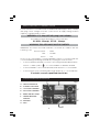
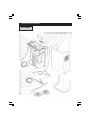
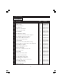
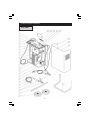
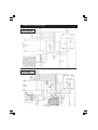
HEAVY DUTY BATTERY
BOOSTERS / CHARGERS
MODEL Nos. BC260N & BC335
OPERATING & MAINTENANCE
INSTRUCTIONS
0707
Thank you for purchasing this CLARKE Battery Charger. These units are suitable for charging
and boosting 12 or 24 Volt lead acid batteries.
Before attempting to operate the unit, please read this instruction manual thoroughly, and
follow all directions carefully. By doing so you will ensure the safety of yourself, and others
around you, and at the same time, you should look forward to the unit giving long and
trouble free service.
GUARANTEE
This product is guaranteed against faults in manufacture for 12 months from date of purchase.
Please keep your receipt as proof of purchase.
This guarantee is invalid if the product has been found to have been abused in any way,
or not used for the purpose for which it was intended, or to have been tampered with in
any way. The reason for return must be clearly stated.
This guarantee does not affect your statutory rights.
CONTENTS
PAGE
Specifications ................................................................................................ 2
Safety Precautions ........................................................................................ 3
Electrical Connections ................................................................................. 4
Parts Identification ........................................................................................ 4
Procedure For Normal Charging ............................................................... 5
Procedure For Normal Charging with Timer ............................................. 5
Procedure For Engine Starting ..................................................................... 6
Parts Lists & Diagrams ................ BC260N ................................................... 7 - 8
BC335 ...................................................... 9 - 10
Wiring Diagrams ............................................................................................ 11
SPECIFICATIONS
MODEL
260N
335
Supply Voltage
230
230
Max Charge (Amps)
40
50 (cont)
Max Boost (Amps)
Boost/Charge (Volts)
Internal Fuse Rating
Internal Fuse Part No.
250
300
12/24
12/24
200A
300A
EM22220008
EM22220011
Part No.
When disposing of this product, ensure it is disposed of according to all local
ordinances at a proper disposal facility. DO NOT dispose of with general waste.
2
IMPORTANT: SAFETY PRECAUTIONS
PLEASE READ BEFORE USING THIS UNIT
1.
WARNING: Some electronic equipment can be damaged by boost
charging or use of start facility. Check your vehicle handbook before using
your Start ’N’ Charge. If in doubt consult the vehicle manufacturer.
Nevertheless, you should not operate this equipment unless you are fully
conversant with vehicle electrical systems, and battery charging techniques.
2.
WARNING: Because highly inflammable hydrogen gas is released in the
process of battery charging, please remember to switch OFF the charger
first, and so avoid sparking which will occur when CONNECTING OR
DISCONNECTING LIVE LEADS.
3.
Black negative (-ve) lead must always be clipped to the negative, and Red
positive (+ve) lead must always be clipped to the positive.
When charging with battery installed in vehicle, or boosting, FIRST connect the
appropriate lead to the UNEARTHED battery terminal (on most modern cars this
is the positive (+ve) terminal), then connect the other lead to the chassis (or a
suitable engine bolt) away from the battery and fuel line. It is advisable to
disconnect the unearthed terminal from the battery, when charging in situ.
When disconnecting, remove the chassis lead FIRST, then the battery lead.
4.
To prevent battery overheating and consequent damage, use the BOOST
facility sparingly and do not exceed our recommendations.
5.
Battery acid is highly corrosive. If spillage occurs, wipe off immediately and
wash copiously with water. Particularly avoid contact with the eyes, but if this
occurs, you must seek medical advice.
6.
When charging is completed, ensure that the vehicle battery leads are
secured to the proper terminals which should be clean and lightly smeared
with petroleum jelly to prevent corrosion. Finally, re-check the electrolyte level.
7.
Do not expose this unit to rain.
8.
Never touch together the negative and positive leads on this unit whilst the
unit is switched on.
9.
Never attempt any electrical or mechanical repair. If you have a problem
with your machine contact your local dealer for service information.
10.
WARNING: Certain types of sealed or maintenance-free batteries need
extra care when charging. Please consult battery manufacturers instructions
before using this unit.
11.
WARNING: Since toxic fumes may be released during battery charging,
ONLY USE THIS UNIT IN A WELL VENTILATED AREA.
12. Before charging ensure the battery terminals are clean and that the cells are filled
with electrolyte to the correct level by adding distilled water where necessary.
3
ELECTRICAL CONNECTION
Connect the three core mains lead to a suitable industrial supply isolator, or heavy
duty plug. These chargers must be connected to a supply having a rated
capacity of greater than 13 Amps.
WARNING: A 13 Amp (BS1363) plug is not suitable.
The maximum input amperages for these units are:
BC260N - 40amps, BC335 - 36amps
WARNING: THIS APPLIANCE MUST BE EARTHED
IMPORTANT: The wires in the mains lead are coloured in accordance with the
following code:
Green & Yellow - Earth
Blue
-
Neutral
Brown
-
Live
As the colours of the flexible cord of this appliance may not correspond with the
coloured markings identifying terminals in your plug proceed as follows:
•
Connect GREEN & YELLOW coloured cord to plug terminal marked with a
letter ‘E’ or Earth symbol ‘
’ or coloured GREEN or GREEN & YELLOW.
•
Connect BROWN cord to terminal marked with a letter L or coloured RED
•
Connect BLUE cord to terminal marked with a letter N or coloured BLACK
If in doubt, consult a qualified electrician.
PARTS IDENTIFICATION
Fig. 1
A - Timer Control Knob
B - Current Control Knob
C - 12 V Positive Terminal
D - 24 V Positive Terminal
E - Mains Indicator Lamp
F - Thermal Overload
Indicator
G - Ammeter
H - Fuse
4
PROCEDURE FOR NORMAL CHARGING
NOTE: All references in brackets refer to Fig. 1
1)
Before charging or boosting, ensure that the cells are filled with electrolyte to the
correct level by adding distilled water where necessary.
2)
Where appropriate we recommend that the non-earthed lead on the battery is
disconnected prior to charging. It is possible that damage may occur to any
electronically controlled system fitted to the vehicle such as engine management,
anti-theft alarm, alternator etc.
3)
Check that the mains supply is OFF and the Current Control Knob (B) is in the ‘O’ OFF position.
4)
Connect the appropriate lead to the unearthed battery terminal (on most modern
cars this is positive (+ve) terminal), then connect the other lead to the chassis (or a
suitable engine bolt) away from the battery and fuel line.
NOTE: Ensure the RED (+ve) lead is plugged into the 12V or 24V receptacle, depending
upon the voltage of the battery to be charged
5)
Remove the battery filler caps, where appropriate, during charging in order to prevent
the build up of dangerous gases within the battery.
6)
Switch ON the mains supply
7)
Turn the Current Control Knob (B) to the position necessary to obtain the required
charge rate, as indicated on the ammeter - 3 charging rates are provided.
CAUTION: Avoid high charge rates with sealed batteries
8)
Keep the battery on charge until the Ammeter (G) reads zero (or 0-2 amps) or has
stopped moving down, then turn the Current Control Knob (B) to the OFF position.
10) When disconnecting the charger, disconnect 1. supply, 2. chassis conductor
and 3. battery conductor, IN THAT ORDER.
Important:
If the fixed positive lead and the fixed negative lead are connected to the wrong
terminals, then a flash will occur when the 2nd Clamp is attached. Damage to the
charging unit and the battery will be avoided as your START’N CHARGE is fitted with
a polarity protection feature. It will however be necessary to replace the internal
fuse. Remove the black plastic cover on the front panel (marked ‘fuse’) and replace
the burnt fuse with an exact replacement. See ‘Specifications’ for replacement fuses.
CHARGING WITH TIMER
1.
Follow the same instructions as for NORMAL CHARGING UP TO AND INCLUDING PARA. 6
2.
Turn the timer control knob (A) clockwise to the desired charging time setting.
3.
Switch ON the mains supply.
4.
Turn the Current Control Knob (B) clockwise to position 5 or 6, to obtain the desired
charging rate as indicated on the ammeter.
5
Notes on charging procedure.
*
A complete charge is best done slowly in order to protect your battery We
recommend the charging ratebe no more than 10% of the battery capacity rating
(AH). eg. a typical battery has a rating of 40 Ampere Hours, therefore the charging rate
should be 4 amps , and a complete charge will take 10 hours.
**
If a low current reading (2 amps or less) is seen on the gauge, this may indicate that the
battery is either (a) already fully charged or (b) at the end of its useful life and in need
of replacement. Do not charge the battery for longer than is necessary.
Check the SG of the battery with a hydrometer
PROCEDURE FOR ENGINE STARTING
Note: We recommend that before attempting to boost start you charge the battery for 10-15
minutes. This will improve the chance of a first time start, particularly with big engines. When
the battery is completely flat, you must charge the battery for 10-15 minutes before attempting
to start, otherwise you may cause damage to the vehicle electronic systems.
a)
Check that mains supply switch is OFF and the Current Control Switch is in the OFF
position.
b)
Connect the cables as for normal charging.
c)
Switch ON the mains supply.
d)
Turn the Current Control Knob (B) in the BOOST START position.
e)
Turn the vehicle’s ignition switch to ‘start’, then press the button on the Remote Control
to provide a boost.
IMPORTANT: If the engine fails to start after a MAXIMUM of 10 seconds, release the button on
the remote control, and the ignition switch. You must then wait for at least 30 seconds before
retrying. Failure to follow this procedure may cause damage to some electronic equipment
on the vehicle and may also damage the battery and the Start ‘N’ Charge unit, which could
invalidate your guarantee.
f)
When the engine has started, switch the Current Control knob (B) to the OFF position,
then disconnect the charger. Disconnect 1. supply, 2. chassis conductor and 3.
battery conductor, IN THAT ORDER.
6
PARTS DIAGRAM
BC260N
7
PARTS LIST
BC260N
No.
01
Description
Qty
Part No.
Switch Knob 0.34
1
EM21690015
02
Switch 12 A
1
EM22205133
03
Timer 16A 250V
1
EM22215001
04
Timer Knob
1
EM21690034
05
Upper Control Panel
1
EM33710273
06
Ammeter 50A/Start
1
EM22600027
07
Front Frame
1
EM21690322
08
Rectifier Pms 12/2/2
1
EM22400045
09
Complete Thermostat 1004 + Support
1
EM04600113
10
P.C.Board For Remote Control
1
EM22700001
11
PVC Input Cable 3x2,5 M.2,5
1
EM20220020
12
Transformer Starter 230V
1
EM44105046
13
Lower Panel
1
EM33700028
14
Remote Control Cable Without Plug
1
EM40210768
15
Black Cable 16 Sqmm Mt.2,5 W/Clamp120
1
EM43200016
16
Red Cable 16 Sqmm
1
EM04600067
17
Earth Clamp (pair) 120A
1
EM22110005
18
Wheels-Axle D.20
1
EM55200001
19
Wheel 0.175 Rubber Hole D.20
2
EM21625009
20
Fuse Box Cover
1
EM21690110
21
Fuse 200A
1
2EM2220008
22
Orange Pilot-lamp 220V
1
EM22610014
23
Green Pilot-lamp 220V
1
EM22610008
24
6 Lobe Hand-wheel D.40
2
EM21800042
25
Insulating French Washers
2
EM21615012
26
Cable Clamp For Hose D.10 Grey
2
EM21605034
27
Front Panel Aut.700
1
EM33700722
28
Cover Panel Aut.700
1
EM33705346
Handle Aut.700
1
EM33725080
29
8
PARTS DIAGRAM
BC335
9
PARTS LIST - BC335
No.
Description
Qty
01
Switch Knob
1
EM21690015
02
Switch 12 A
1
EM22205133
03
Timer Knob
1
EM21690034
04
Timer 16a 250V
1
EM22215001
05
Upper Control Panel
1
EM33710285
06
Ammeter 50A
1
EM22600017
07
Front Frame
1
EM21690322
08
Rectifier Pms 20/2/2
1
EM22400011
09
Complete Thermostat + Support
1
EM04600113
10
P.C. Board
1
EM22700001
11
Input Cable 3x2.5 M2.5
1
EM20220020
12
Transformer
1
EM44105075
13
Thermostat Support
1
EM04600261
14
Contactor 220v I0A
1
EM22225006
15
Lower Panel
1
EM33700028
16
Remote Control Cable
1
EM40210768
17
Black Cable 16 Sqmm
1
EM43200016
18
Earth Cable 16 50mm
1
EM43200015
19
Dinse Plug 25sqmm
1
EM22100001
20
Clamps 120A
1
EM04600067
21
Wheels-axle
1
EM55200001
22
Wheel D.175 Rubber
2
EM21625009
23
Big Fuse Box Cover
1
EM21690110
24
Fuse 300A
1
EM22220011
25
Orange Pilot-lamp 220V
1
EM22610014
26
Green Pilot-lamp 220V
1
EM22610008
27
Female Dinse Plug 25sqmm
2
EM22100002
27
Cable Clamp + Screw
2
EM04600234
28
Cable Clamp
1
EM21605009
29
Front Panel
1
EM33700722
30
Panel
1
EM33705346
31
Handle
1
EM33725080
10
Part No.
WIRING DIAGRAMS
BC260N
BC335
11