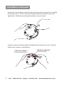
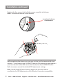
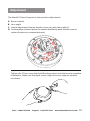
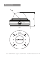
1
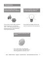
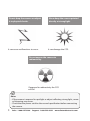
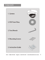
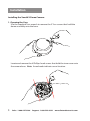
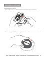
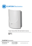
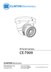
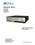
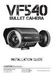
VX10
The lightning flash with an arrowhead symbol, within an equilateral
triangle is intended to alert the user to the presence of uninsulated
dangerous voltage within the product’s enclosure that may be of
sufficient magnitude to constitute a risk of electric shock to persons.
The exclamation point within an equilateral triangle is intended to alert
the user to the presence of important operating and maintenance
(servicing) instructions in the literature accompanying the appliance.
INFORMATION - This equipment has been tested and found to comply with
limits for a Class A digital device, pursuant to part 15 of the FCC Rules.
These limits are designed to provide reasonable protection against harmful
interference when the equipment is operated in a commercial environment.
This equipment generates, uses, and can radiate radio frequency energy
and, if not installed and used in accordance with the instruction manual, may
cause harmful interference to radio communications.
Operation of this equipment in a residential area is likely to cause harmful
interference in which case the user will be required to correct the interference at his own expense.
WARNING - Changes or modifications not expressly approved by the
manufacturer could void the user’s authority to operate the equipment.
CAUTION : To prevent electric shock and risk of fire hazards:
u Do NOT use power sources other than that specified.
u Do NOT expose this appliance to rain or moisture.
This installation should be made by a qualified service person and
should conform to all local codes.
Sales: 1-800-447-3306
Support: 1-800-549-6393
www.clintonelectronics.com
UL Safety Fulfillment
USER’S MANUAL
IMPORTANT SAFETY INSTRUCTIONS
1) Read these instructions.
2) Keep these instructions.
3) Heed all warnings.
4) Follow all instructions.
5) Do not use this apparatus near water.
6) Clean only with dry cloth.
7) Do not block any ventilation openings. Install in accordance with the manufacturer’s instructions.
8) Do not install near any heat sources such as radiators, heat registers, stoves, or other
apparatus (including amplifiers) that produce heat.
- or grounding-type plug. A polarized plug
9) Do not defeat the safety purpose of the polarized
has two blades with one wider than the other. A grounding type plug has two blades and a third
grounding prong. The wide blade or the third prong are provided for your safety. If the provided
plug does not fit into your outlet. Consult an electrician for replacement of the obsolute outlet.
10) Protect the power cord from being walked on or pinched particularly at plugs, conveniance
repeptacles, and the point where they exit from the apparatus.
11) Only use attachments/accessories specified by the manufacturer.
12) Use only with the cart, stand, tripod, bracket, or table specified by the manufacturer, or sold
with the apparatus. When a cart is used, use caution when moving the cart/apparatus combination
to avoid injury from tip-over.
13) Unplug this apparatus during lightning storms or when unused for long periods of time.
14) Refer all servicing to qualified service personnel. Servicing is required when the apparatus
has been damaged in any way, such as power-supply cord or plug is damaged, liquid has
been moisture, does not operate normally, or has been dropped.
Table of Contents
Warning
Precautions
Components
Installation
n Opening the Case
n Mounting the Camera
n Reassemble the Camera
Adjustment
Specifications
Dimension (inches)
Sales: 1-800-447-3306
Support: 1-800-549-6393
1
2
4
5
10
11
12
www.clintonelectronics.com
Warning
The camera requires periodic inspection.
Contact an authorised technician to carry out the inspection.
Stop using your camera when you find it malfunctioning.
If the camera emits smoke or is unusually hot for a long period, a fire may be
caused.
Do not install the camera on a surface that can not support it.
If the camera is installed on an inappropriate surface, it may fall and cause injury.
Do not hold plug with wet hands.
It could cause an electric shock.
Do not dis-assemble the camera.
It may result in an electric shock or other hazards.
Do not use the camera close to a gas or oil leak.
It may result in a fire or other hazards.
1
Sales: 1-800-447-3306
Support: 1-800-549-6393
www.clintonelectronics.com
Precautions
Do not install the camera in
extreme temperature conditions.
Only use the camera under conditions
where temperatures are between
-20°F ~ 122°F. Be especially careful to
provide ventilation when operating
under high temperatures.
Do not install the camera under
unstable lighting conditions.
Severe lighting change or flicker can
cause the camera to work improperly.
Do not touch the front lens of the
camera.
This is one of the most important
parts of the camera. Be careful not to
leave fingerprints on the lens cover.
Sales: 1-800-447-3306
Support: 1-800-549-6393
www.clintonelectronics.com
2
Do not drop the camera or subject
it to physical shocks.
It can cause malfunctions to occur.
Never keep the camera pointed
directly at strong light.
It can damage the CCD.
Do not expose the camera to
radioactivity.
If exposed to radioactivity the CCD
will fail.
Notes
•If the camera is exposed to spotlight or object reflecting strong light, smear
or blooming may occur.
•Check that the power satisfies the normal specification before connecting
the camera.
3
Sales: 1-800-447-3306
Support: 1-800-549-6393
www.clintonelectronics.com
Components
Sales: 1-800-447-3306
Support: 1-800-549-6393
www.clintonelectronics.com
4
Installation
Installing the Vandal X Dome Camera:
1. Opening the Case
Use the supplied Torx wrench to remove the 3 Torx screws that hold the
dome assembly onto the base.
5
Locate and remove the 4 Phillips head screws that hold the inner case onto
the camera base. Note: Arrowheads indicate screw location.
Sales: 1-800-447-3306
Support: 1-800-549-6393
www.clintonelectronics.com
Installation continued
2. Mounting the Camera
Remove the camera assembly from the camera base as shown below.
If desired apply the EVA foam ring to the bottom of the camera base as shown.
Sales: 1-800-447-3306
Support: 1-800-549-6393
www.clintonelectronics.com
6
Installation continued
Secure the camera base to the desired mounting surface using the 4 supplied
mounting screws. Choose the mounting hole pattern that best suits your
application. Multiple mounting hole patterns are provided.
Feed the power and video cables through the desired access hole. Note the
cable access options shown below.
Cable Access Option 1:
Stud/wall anchor hole
7
Sales: 1-800-447-3306
Cable Access Option 2:
Conduit box hole
Support: 1-800-549-6393
www.clintonelectronics.com
Installation continued
3. Reassemble the Camera
Replace the camera assembly into the mounting base as shown below.
Align the tab with the slot when reassembling.
Sales: 1-800-447-3306
Support: 1-800-549-6393
www.clintonelectronics.com
8
Installation continued
Replace the four screws that hold the camera assembly to the base.
Note: Arrowheads indicate screw location.
Arrowhead indicates
screw location.
Before replacing the dome cover you may wish to test the camera with a test
monitor. To test, plug in the CE-REMOTE into the DIN connection, and connect
your test monitor to the BNC connection located on the CE-REMOTE cable.
Refer to camera manual for detailed OSD adjustment settings.
Note: Not all Vandal X Dome Cameras support this function. Refer to
specification for OSD Adjustment and Test Monitor Connection compatibility.
9
Sales: 1-800-447-3306
Support: 1-800-549-6393
www.clintonelectronics.com
Adjustment
The Vandal X Dome Camera has four position adjustments:
A. Barrel rotation
B. Lens angle
C. Lateral adjustment (loosen thumb screws on each side to adjust)
D. Camera plate rotation (pinch the camera bracket by each thumb screw to
rotate clockwise or counterclockwise)
B
A
C
D
Tighten the 3 Torx screws that hold the dome cover onto the base to complete
installation. Make sure that each screw is tight to ensure superior weather
resistance.
Sales: 1-800-447-3306
Support: 1-800-549-6393
www.clintonelectronics.com
10
Specifications
Camera
CE-VX10
Image Sensor
1/3 Inch SONY Color CCD
Resolution
420 TV Lines
Effective Pixels
512 (H) x 492 (V)
Scanning System
525 Lines, 2:1 Interlace
S/N Ratio
More than 48dB
Sync System
Internal
Minimum Illumination
1.0 Lux
Shutter Speed
1/60 ~ 1/100,000 sec.
Lens
4 ~ 9mm
Video Output
1.0 Vp-p, 75Ω
Power Consumption
Max. 110mA (AC24V), Max. 220mA (DC12V)
Power Requirement
DC12V / AC24V
Operating Temperature
-20°F ~ 122°F
Weather Rating
IP 68
Dimensions
5.74” (Dia.) x 4.13” (H)
Weight
2.75 lbs.
Information in this document is subject to change
11 Sales: 1-800-447-3306
Support: 1-800-549-6393
www.clintonelectronics.com
Dimensions
Ø
4.13”
6”
3.8
5.74”
Sales: 1-800-447-3306
Support: 1-800-549-6393
www.clintonelectronics.com
12
MEMO
v.07.09.09